1
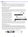
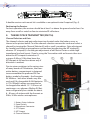
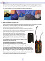
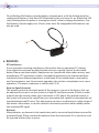
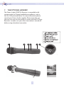
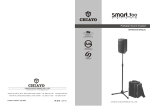
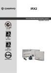
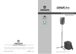
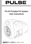
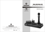
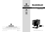
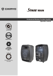
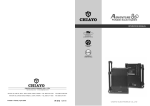
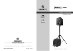
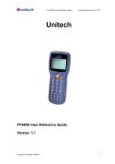
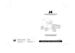
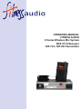
Wireless Microphone System Operating Manual
OPERATING MANUAL
FITNESS AUDIO
U Series Wireless Mic System
SDR-5716 Receiver
SM-716 / MT-U8 Transmitter
Wireless Microphone System Operating Manual
1. INTRODUCTION
Congratulations on your purchase of the state-of-the-art Fitness Audio PLL Synthesized
16 channel frequency agile UHF high band professional wireless system. Please read
this operating manual thoroughly in order to familiarize yourself with the controls
before using them.
2. FRONT AND REAR PANEL CONTROLS
U Series
Receiver
1. GND
1 2
2. +
3
3. -
SDR-5716
DC-IN
MIX
ANT.B
BALANCED
1. Power Switch
2. Diversity Indicator
3. RF Signal Indicator
4. AF Signal Indicator
5. Channel LED
6. Channel Selectors
7. Volume Control
MAX
SQ
AF OUT
10-15V
ANT.A
8. Antenna B Socket
9. Fixed Mic-level Balanced output
10. Unbalanced Variable Line-level output
11. Squelch Control
12. DC IN Jack
13. Antenna A socket
Channel Selection
The first thing you see when you turn on the receiver is 3 pairs of numbers that
signify the frequency of the pre-set channel 00 (63.03.50 = 630.350MHz in the 630
Group). The channel changing buttons are software locked. To release the lock so
that you can change it to use another channel just press and hold both Channel buttons in at the same time. After 3 seconds the Channel display will flash and you can
change and check the channels using the and buttons. Once you have chosen a
new channel, leave it flashing for 15 seconds before it locks on as indicated by a solid
channel number. Don’t forget to set your transmitter channel to match.
Auto Scanning
While the channel buttons are software locked, the system will scan all channels and
stop at the first clear one by pressing for 3 seconds.
2
Wireless Microphone System Operating Manual
Group selection
The group selection mode can be activated by pressing for 3 seconds. The LEDs
then flash either “FS”, “FA” or “Fb”, which can be chosen with the and buttons.
(FS: Standard 16 channels, FA: Standard channel 0-7 repeats, Fb: Standard channel
8-0F repeats) After 15 seconds idling the group setting is automatically saved.
3. RECEIVER INSTALLATION
Audio output connection
There are two audio outputs on the back of the U-Series SDR5716 Receiver, a Mic-level
balanced XLR-M and Line-level unbalanced 6.35mm jack. We have supplied you with a
balanced cable that goes from the XLR output into a TRS 6.35mm jack plug as used on
the Fitness Audio Aeromix mixers.
This cable is a perfect match for an
Aeromic/Cyclemic or E•Mic/V•Mic,
the balanced cable connection will
deliver the highest sound quality
possible with any microphone, with
more “body” in the voice being the
main audible difference. This audio
connection is shown in figure 2.
1. GND
1 2 2. +
3
DC-IN
3. -
SQ
ANTENNA-B
BALANCED AF OUT
10V-15V
ANTENNA-A
However, if your mixer has an XLR input socket, then it’s best to purchase
Fig.2
a balanced XLR-F to XLR-M cable to
connect the receiver to the Mic Input. Some mixers will also accept an unbalanced
jack to jack lead mic connection with the receiver’s output volume control adjusted
down to suit as an alternative connection, but a balanced cable connection is the
better one to use.
Rack Mounting the Receiver
The Fitness Audio SDR5716 Receiver is a 19” half-rack mount design and is supplied
with a specially designed 19” rack mount adapter so can be bolted into equipment
cabinets. Assemble as shown in Fig 3. We have also supplied you with a pair of antenna
extension cables so that the two antennas can be mounted into the holes on the rack
ears out front in the air and not trapped inside a steel box. Use the star washer and the
nut on the inside of the rack ears to get a firm non-slipping mount.
3
Wireless Microphone System Operating Manual
A double receiver rack mount kit is available as an optional extra if required (Fig. 4).
Positioning the Receiver
For best operation, the receiver should be at least 1m above the ground and at least 1m
away from a wall or metal surface to minimize RF reflections.
4. THE BELT-PACK TRANSMITTER (SM716)
Channel Selection and Gain
The channel selector and gain adjustment are located under the battery cover as
shown in the picture below. To make channel selection remove the cover and select a
channel by turning the Channel Selector(6) with a small screwdriver. Gain adjustment
for Lavalier and Headset microphones can be done by adjusting the MT trimpot(5),
whereas GT trimpot(4) is for the gain adjustment of an Electric Guitar or other high
impedance line level inputs. If you’re using the Transmitter with an Aeromic then turn
down the MT trimpot to minimum. If
using an E•Mic or V•Mic then leave the
MT trimpot at full and turn down only if
distortion is evident.
Due to minor variations in the casing sizes
of many brands of 9V batteries, the transmitter battery compartment is designed
to accommodate the preferred 9V size
battery made by Eveready - the Energizer
9V Alkaline – but other brands may also
work well. Re-chargeable Ni MH batteries
@ 170-190mAH ratings may need to be
re-charged after about 1.5 – 2.0 hours of
continuous use, whereas Alkaline 9V Batteries will generally be suitable for about
6 – 8 hours of airtime with the Aeromic or
E•Mic/ V•Mic wireless microphones.
1. Battery Status Indicator
2. Power Switch
3. Microphone Connector
4. GT Trimpot
5. MT Trimpot
6. Channel Selector
4
Wireless Microphone System Operating Manual
A range of transmitter Pouchbelts in different styles and colours which can be worn under or over your clothes are available for many different users, including fitness instructors, actors, musicians and professional presenters. For more details please consult your
FA System supplier or visit our website www.fitnessaudio.com.au.
Pouchbelts shown L - R: Standard, Hipster, Zipster, Grey Zipster, Beige Theater belt.
5. MINI TRANSMITTER (MT-U8)
If your system has been supplied with a Mini Transmitter then it will already be wired to
an Aeromic or Cyclemic, E•Mic or V•Mic either attached to the frame or
with an Arm Pouch or Waist Pouchbelt to suit.
To select the matching channel to the receiver remove the battery
cover and with the small screwdriver supplied change the channel to
match the one shown on the receiver LED display.
Please note that the MT-U8 is an 8 channel transmitter and will normally be supplied lining up with
channels 00-07 on the receiver. In some countries
a “B” group of channels may also be available (Ch.
08-0F). In both cases the channels line up with the
same number on the receiver and then repeat so that
channel 00 is also channel 08.
Using Multiple Transmitters At One Location
You can use up to four MT-U8/SM716 systems under
the one roof without interference from each other. In the case of
the 630-650MHz range it is channels 00, 03, 04 or 07 in Group A, and,
if you are also using a beltpack transmitter or a Group B Mini Tx in
the same room, then it can be set to a channel in the 08-0F group of
which channels 09, 0B,0D or 0F will work best with the above Group
A channels. There will be different, non-conflicting channels in other
frequency groups supplied around the world so please check with
your dealer or national supplier for this information.
5
Wireless Microphone System Operating Manual
Fit an Alkaline AAA battery into the battery compartment, re-fit the lid and push the
sealed on/off button. A tiny blue LED illuminates to let you know it’s on. When that LED
starts flashing then the power is running low and it’s time to change the battery. One
AAA battery should supply over 5 hours of air time. Re-chargeable AAA batteries can
also be used.
6. REMARKS
RF Interference
If you encounter receiving interference (from other than an operating TV station),
it can often be overcome by adjusting the receiver’s squelch control, as described
below. Please note that wireless frequencies are shared with other radio services, and
according to FCC regulations wireless microphone operations are unprotected from
interference from licensed operations in the band. If any interference is received by
any Government or non-Government operation, the wireless microphone must cease
operation. (The above statement is valid for the U.S.A.)
Receiver Squelch control
The squelch control on the back panel of the receiver is preset at the factory, but can
be adjusted if you must use the system in a high RF interference area. If there is audio
output from the receiver when your transmitter is OFF, adjust the squelch control so
the system will receive the signal from your transmitter but squelch or eliminate the unwanted background RF noise. This adjustment can cause a reduction in usable range of
the wireless transmitter, so set the control to the lowest position which reliably mutes
the unwanted RF signal.
Batteries
Many batteries are known to leak conductive and/or corrosive liquid when not used for
a period of time. Please remove the batteries from the transmitter if it is not to be used
for a period of a few days or more.
6
Wireless Microphone System Operating Manual
7. THE OPTIONAL HANDMIC
The Fitness Audio SDR5716 Receiver is compatible with
certain models of Chiayo handheld microphones such as
the SQ-1016 pictured below. For more information please
consult your Fitness Audio supplier. Please note that you
can only use one mic transmitter at a time with the FA Series
Receivers so make sure your other transmitter is turned off
before using a handmic transmitter.
7
Wireless Microphone System Operating Manual
The Fitness Audio SDR5716 Receiver, SM716 and MT-U8 Transmitters are
covered by a minimum 12 month parts and labour warranty against
manufacturer’s defects from the date of purchase by the first owner.
Longer warranties may apply to the SM716 in some countries.
Warranty Information
(Please retain for your records)
This product was purchased by:
(Your Business) . . . . . . . . . . . . . . . . . . . . . . . . . . . . . . . . . . . . . . . . . . . . . . . . . . . . . . on (date) .. / .. / .. from (Company) . . . . . . . . . . . . . . . . . . . . . . . . . . . . . . . . . of (address) . . . . . . . . . . . . . . . . . . . . . . . . . . . . . . . . . . . . . . . . . . . . . . . . . . . . . . . . . . Model Number(s) . . . . . . . . . . . . . . . . . . . . . . . . . . . . . . . . . . . . . . . . . . . . . . . . . . . Serial Number(s) . . . . . . . . . . . . . . . . . . . . . . . . . . . . . . . . . . . . . . . . . . . . . . . . . . . . FCC & IC Caution:
This device complies with Part 74 of the FCC Rules and Canada licence-exempt RSS-123 standard.
Operation is subject to the following conditions:
(1) This device may not cause interference.
(2) This device must accept any interference, including interference that may cause undesired operation
of the device.
This device complies with FCC RF radiation exposure limits set forth for an uncontrolled environment.
Fitness Audio® Wireless Systems, Aeromic®, E•Mic™ & V•Mic™ Headmics
and Aeromix® Audio Mixers are distributed worldwide exclusively by:
Fitness Audio Distributors
Email: [email protected]
Website: www.fitnessaudio.com.au
Manufactured for Fitness Audio Network P/L
PO Box 321 Alexandria, NSW 1435 Australia
Manufactured by
Chiayo Electronics, 30 Lane 27 Sec.4. Jen-Al Taipei, Taiwan
8