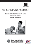
1
SYSTEM INSTALLATION GUIDE
www.soundfield.uk.com
2
i-ceilings Soundfield Systems provide a complete
solution designed for use in teaching and training
environments. They utilise the latest speaker and
infrared technology to create sound reinforcement
systems which combine the highest levels of
performance and flexibility with the minimum of visual
intrusion.
Please remember that Soundfield is a ‘sound
reinforcement’ system, not a public address system;
levels should therefore be set accordingly.
Typical Classroom Coverage:
Please note: These infrared Soundfield Systems are
designed for use in a typical standard sized classroom
(normally up to 60m²) and are not recommended for
use in large room applications such as school halls,
lecture theatres, sports halls, etc...
(For larger applications, we suggest using RF
wireless microphone systems).
The IR wireless microphones use direct/reflected light
emissions and, so, large non-reflective surfaces (light
absorbent surfaces such as black/dark painted walls
or large fabric coverage, etc...) in the classroom which
may reduce coverage must always be considered in
the system’s performance.
Installation of 2 wall sensors in a classroom:
Infrared
remote
sensor
10m in
width
Infrared
remote
sensor
whiteboard
10m in width
Please read this manual carefully before starting the
installation and ensure you have all the equipment
required.
This product should only be installed by a competent installer. The manufacturer accepts no responsibility for any resulting
damage or consequential loss due to incorrect installation.
• It is essential that all equipment mounting trays and safety bonds (safety cable & security clips) are used
and installed correctly.
• The amplifier will get warm during use, so please allow adequate ventilation around the unit.
Should you need to clarify any details with regards to the product or its installation, please contact our technical
support team on 0115 977 0075; we are always happy to provide help and technical advice.
www.soundfield.uk.com
3
Soundfield Equipment Pack Lists
i-ceilings Soundfield Packs are supplied with
the loudspeakers and infrared equipment in
separate boxes.
Before going to site please check you have all
the items required.
Detailed below are the contents lists for each
of the various packs that are available...
• Soundfield Pack F
Pack C
Pack A
1 x CS4000ME/AMP
1 x APA/APL
1 x APA/TRAY
2 x 03284
2 x 03518
1 x IWM-402
1 x IWR-220
2 x IS-20A
2 x EXT CABLE 10
1 x HC-40
2 x AA
1 x IC-1/IC-2
2 x Instructions
Amplified Sound Panel Speaker
CD/MP3/Laptop Wall Plate
Equipment Support Tray
Safety Cable
Security Clip
Pendant Transmitter/Microphone
Infrared Receiver
Infrared Sensor
10 Mtr Extension Cord for IS-20A
Drop-in Charger for IWM-402
Batteries for IWM-402
Connecting Cables
Installation and Operation Manuals
1 x PRO PANEL/AMP
1 x APA/APL
1 x APA/TRAY
2 x 03284
2 x 03518
1 x IWM-402
1 x IWR-220
2 x IS-20A
2 x EXT CABLE 10
1 x HC-40
2 x AA
1 x IC-1/IC-2
2 x Instructions
Amplified Panel Speaker
Sound Panel Speaker (slave)
CD/MP3/Laptop Wall Plate
Equipment Support Tray
Safety Cable
Security Clip
Pendant Transmitter/Microphone
Infrared Receiver
Infrared Sensor
10 Mtr Extension Cord for IS-20A
Drop-in Charger for IWM-402
Batteries for IWM-402
Installation and Operation Manuals
4 x FBT Project 315
1 x IRX
4 x 03284
1 x IWM-402
2 x IS-20A
3 x EXT CABLE 10
1 x HC-40
2 x AA
1 x AV15276
2 x Instructions
Pack B
1 x CS4000ME/AMP
1 x CS4000ME
1 x APA/APL
1 x APA/TRAY
2 x 03284
2 x 03518
1 x IWM-402
1 x IWR-220
2 x IS-20A
2 x EXT CABLE
1 x HC-40
2 x AA
2 x Instructions
Amplified Pro Sound Panel Speaker
CD/MP3/Laptop Wall Plate
Equipment Support Tray
Safety Cable
Security Clip
Pendant Transmitter/Microphone
Infrared Receiver
Infrared Sensor
10 Mtr Extension Cord for IS-20A
Charger for IWM-402
Batteries for IWM-402
Connecting Cables
Installation and Operation Manuals
Pack F
Wallmount Loudspeakers
Wallmount Amplifier/IR Receiver
Safety Cable
Pendant Transmitter/Microphone
Infrared Sensor
10 Mtr Extension Cord for IS-20A
Charger for IWM-402
Batteries for IWM-402
Phono Coupler
Installation and Operation Manuals
Pack G
1 x CS4500
1 x IRX
1 x 03284
1 x IWM-402
2 x IS-20A
3 x EXT CABLE 10
1 x HC-40
2 x AA
1 x AV15276
2 x Instructions
Surface-mount i-ceilings Sound Panel
Wallmount Amplifier/IR Receiver
Safety Cable
Pendant Transmitter/Microphoner
Infrared Sensor
10 Mtr Extension Cord for IS-20A
Charger for IWM-402
Batteries for IWM-402
Phono Coupler
Installation and Operation Manuals
4
Optional Soundfield Equipment
• IS-20A
Extra Infrared Sensor
• Ext. cable 10
10 Metre IR Sensor Extension Lead
• IWH-401
Handheld Transmitter/Microphone
• 7W1B2V4
Rechargeable Battery for IWH-301A
• APA/APL
CD/MP3/Laptop Wall Plate
• APA/LLO
Radio Assisted Hearing Aid Output Plate
5
Infrared Wireless Microphone Technology
This manual is intended for use by installation engineers.
The separate user manual should be left with the user.
Infrared Wireless Microphone
Technology:
As the Systems use wireless infrared to transmit the user’s
voice, some understanding of how this operates is useful...
Infrared is simply invisible light and acts in a very similar way
to ordinary light, a useful feature in classroom applications.
For example, infrared recognises walls as boundaries so
multiple systems can be used without problems.
Whilst it is true that IR can be directional, all our emitters
use high power LED arrays and detectors are wide angle.
Infrared also readily reflects from walls, ceilings and windows
so full coverage is easily achievable. Frequency allocation
problems are eliminated and any transmitter can be used
with any receiver; as a result these systems are both easy
to commision and very flexible in use.
AC Power Requirements:
Pack A, B, and C Systems:
A single 13 amp power point is all that is required
as all ancillary Soundfield system items are powered
directly from the panel amplifier. If two speakers are
required, a further slave Sound Panel (set to 8 ohms)
can be connected to the extension speaker terminals
of the Panel Amp (see page 10 for connection details).
Pack F & G Surface-mount Systems:
A single 13 amp power point is all that is required
as all ancillary items are powered from the IRX
Receiver/Amplifier.
Cable Requirements:
Mains & Audio:
All mains supply cables (terminated with 13 amp UK plugs) are included with kits,
as are the interconnection cables between the infrared receiver and amplifier.
Infrared Receiver and External Detectors:
Two ready-terminated 10 metre coaxial extension cables are provided for the
connection of the extension IS-20A infrared detectors. If required, these can be
extended to 20 metres by means of a further extension cable and male-to-male
coupler. (The Pack F System is supplied with 3 extension cables and a
male-to-male coupler). For distances of over 20 metres please consult
our technical support team.
6
Outreach Input Plates
A maximum of 5 Outreach Plates can be used with
the i-ceilings amplified Sound Panel or IRX Wallmount
Amplifier. The APA/APL (supplied with the packs) is
intended to be used for the connection of a laptop,
CD, MP3 player (or similar audio signal) and should be
located in a convenient position near to the teaching
position.
Outreach Plates are active with balanced outputs
and, as such, can be daisy-chained together to
provide multiple inputs as required, each with its own
dedicated volume control. By this means it is possible
to provide a flexible input structure to cater for almost
any conceivable requirement.
• APA/APL Outreach Plate
for AV inputs
Low Level Output Plates (APA/LLO):
These optional units are intended to facilitate the
connection of individual hearing assistance systems
to the Soundfield system. The plate is supplied with
a 3.5mm 2pole jack socket with an output level of
775volts nominal, set by means of a user adjustable
level control.
Cable requirements are as Outreach input plates, but
a separate cable must be provided where this facility
is installed.
All Outreach input and output plates require a single gang
socket box with a minimum depth of 25mm.
• APA/LLO Outreach Plate for
assistive hearing systems
Outreach Plate connection cable specification:
The cable between the speaker panel, the first and any following Outreach Plates must be to the following minimum
specification: 1 pair twisted and screened for audio, plus 1 additional pair for power. ‘West Penn’ 357 supplied by
CIE-Group, or any good quality quad microphone cable should be suitable.
A wide range of Outreach Plates to suit various other interface requirements is available; please call CIE-Group
for details.
7
Sound Panel Loudspeaker Installation
Sound Panel Loudspeaker
positioning and installation
(Packs A, C & G):
Infrared remote sensor
In systems using only one i-ceilings Sound Panel,
the speaker unit should ideally be installed in the
ceiling grid slightly to the rear of the classroom
using the teaching position as a datum and as
near as possible to the centre line of the other axis
(see Diagram 1).
(Pack B):
i-ceilings
Sound Panel
loudspeaker
When 2 panels are used, the exact positioning will
be dictated by the shape of the classroom but
the locations should be chosen to give the best
possible coverage.
Infrared remote sensor
• Diagram 1
Sound Panel Cabling:
Take care to route all cables in such a way that
they cannot rest on the rear of the Sound Panel.
When completing the installation be sure to fit the
safety bonding wire to each speaker.
Finally check that no debris has been dropped
on the panel. Remove everything; you would be
amazed at the effect a 10mm cable off-cut can
produce!
Remote Infrared Sensor (IS-20A)
installation:
Two remote IR sensors are supplied with all kits.
These should be installed at either end of the
classroom just below ceiling level. Generally the
centre of the wall behind the teaching position and
the same position on the opposite wall will give the
best coverage (see Diagram1 above) (alternatively
position on opposite sides of the room).
The IS-20A is a 170 degree wide angle detector
and should be angled slightly downwards to give
the best possible coverage.
Please ensure to make all connections before
switching on power to the amplifier supply.
8
Conventional Wall Speaker Positioning
Where FBT Project 315 Loudspeaker option is used (Pack F):
If possible, the 4 speakers should be installed in Position 1 as shown in
Diagram 2.1; if this is not possible then Position 2 shown in Diagram 2.2
can be used.
Before installation the rotary switch at the rear of the speakers must
be set to 8Ω. Do not attempt to run the speakers at higher power
settings/100v line as this will damage the amplifier.
Safety Note
It is most important that the supplied safety cables and security clips are used and fitted
correctly on each loudspeaker as part of the installation.
• Diagram 2.1 - FBT wall speaker Position 1
• Diagram 2.2 - FBT wall speaker Position 2
IRX Wallmount Amplifier/IR Receiver
When an Armstrong Sound Panel is used, the amplifier is an integral part. It supplies
power to the IR receiver and any Outreach points as well as providing audio
inputs and controls; please refer to IAPA section for details on connection
and commissioning.
However, where surface-mount speakers (Pack F & G) are used, the IRX Wallmount
Amplifier/IR Receiver is provided as part of the kit. It should be installed adjacent to the
whiteboard (or front of the classroom) at a height convenient to allow adjustment of the
level controls. The associated Outreach Plate should also be installed close by.
Please refer to page 12 for details of IRX installation and commissioning.
9
IAPA Integrated Panel Amplifier
Introduction:
The IAPA (Integrated Armstrong Panel Amplifier)
consists of a 20W power amplifier pre-installed on
an Armstrong i-ceilings Sound Panel. Sound Panels
can be supplied with a wide range of ceiling finishes
allowing the unit to be installed in any Armstrong
suspended ceiling.
For advice on matching non-Armstrong suspended
ceilings, please contact the CIE-Group sales team.
IAPA Features:
The IAPA amplifier has two inputs; one is at line level
allowing the use of remote Outreach input plates such as the
APA/APL, the other input is at a level suitable for connection
to a Chiayo IWR220 (or similar infrared or RF wireless
microphone receiver). An 18v DC supply is available from
the amplifier to drive the Outreach plates and a 15v DC
supply to power the IR receiver. Both inputs have their own
level controls.
An additional line level output, 18v DC supply and external
low impedance speaker output are also features of this
unit.
The unit is fitted with ‘High’ and ‘Low’ tone controls to
allow adjustment of the frequency response of the panel.
The frequencies at which the controls operate have been
chosen to allow speech clarity to be optimised to the
acoustic environment.
All the connections to the unit are externally accessible and
are of the removable screw terminal type, allowing for quick
and easy connection.
IAPA Specifications:
Rated Output:
20W RMS into 8 ohms
Frequency Response:
100Hz ~ 18kHz ±3dB
THD (At 1kHz):
Better than 0.1% at rated output
Tone Controls:
Low 1kHz ±12db
Line Input:
500mv, 600 Ohm balanced
Mic. Input:
200mv, 10k Ohm unbalanced
18v Output:
18v DC, fused at 100mA max.
15v Output:
15v DC, fused at 500mA max.
Line Output:
750mV, 600 Ohm Balanced
Power Consumption:
35W max.
Power Input:
230v AC 50Hz via IEC socket
Case:
White painted steel
High 10kHz ±12db
10
IAPA Connection Details
IAPA Connection Details:
(refer to Diagram 3 on page 11)
• Line In:
Balanced line level input terminals for connection of up to five remote Outreach Input plates (APA/APL, etc).
• Mic Rcvr In:
Unbalanced microphone level input terminals for connection of a Chiayo IWR-220 infrared wireless
microphone receiver. It is also possible to use this input to connect Chiayo RF radio microphone receivers.
Contact CIE-Group Technical Support (0115 977 0075) for advice.
• 18v DC Out (Line Level / Line Sig Out):
18v DC supply terminals providing power to the Outreach plates. These terminals will provide a combined
maximum output current of 100mA.
• 15v DC Out: (Mic Rcvr)
15v DC supply terminals providing power to the IWR-220 receiver only. These terminals will provide a combined
maximum output current of 500mA.
• Line Output:
Balanced line level output terminals available on the IAPA for connection to the line level input of other equipment
such as the APA/LLO Outreach plate or Induction Loop amplifiers. These can be used for connecting multiple
i-ceilings panels in larger rooms where one speaker would not give sufficient sound coverage.
• Ext Spkr:
External 8 ohm speaker terminals for powering a single additional Armstrong CS1000 or Pro series panel. Note:
damage to the amplifier will occur if speakers with a total impedance of less than 8 ohms are connected to these
terminals.
• Mains In:
The mains input should be connected using an IEC type connector. The supply input should be 230V AC
(±10%) 50Hz.
Warning
No connections should be made to the unit whilst the mains power is connected
A IN+
A INV+
GND
A IN+
A INV+
GND
APL
Outreach
Input Plate
(Optional)
SPARE
A OUT+
A OUT-
SPARE
A OUT+
A OUT-
SCRN
SIG +
SIG -
SHOULD BE CONNECTED
NO MORE THAN 5 OUTREACH PLATES
4-core screened cable
18v +
0v
SIG +
SIG 18v +
0v
APL
Outreach
Input Plate
SCRN
SIG +
SIG 18v +
0v
4-core screened cable
Gnd
L in e In
MIC OUTPUTS
Gnd
L in e S ig O u t
IR Mic
SENSOR INPUTS
IR RECEIVER
OUTPUT LEVEL
(SET AT MIC)
TONE
POWER CONNECTOR
Low
15v R c v r P w r
1/4" JACK
Gnd
M ic R c v r In
Mic Level
IR S E N S O R
18v D C O u t
Line Level
DC IN
18v DC Out
High
4-core screened cable
230V AC
MAINS IN
_
0v
18v +
SIG SCRN
SIG +
+
IR S E N S O R
IAPA CONNECTION DETAILS
IAPAinst.DSN
FILE:
may be supplied
O
03/05/07
O
group
REV
CIE -
TO Outreach
OUTREACH OUTPUT
To
OutputPLATES
Plates
(optional)(Optional)
To 8ohm speaker or i-ceilings
TO 8ohm SPEAKER or I-CEILING PANEL
panel (optional)
(Optional)
IEC MAINS INPUT
TITLE:
IWR-220
shown but
other M but
odels
may bemodels
supplied
IWR-220
shown
other
E x t S pk r
POWER
11
Diagram 3 - IAPA Connection Details
12
IRX Wallmount Amplifier/IR Receiver
The IRX unit is a wallmount system featuring 20W amplifier and in-built infrared
receiver, developed specifically for Soundfield systems using conventional
wallmount loudspeakers or the i-ceilings CS4500 surface-mount Sound Panel.
It has been designed to be both user-friendly in the classroom, whilst ensuring
complete safety and security in such a welfare-critical environment.
The in-built amplifier features two inputs; one is at line level allowing the use of
remote Outreach input plates such as the APA/APL, the other input controls the
level of the internal infrared microphone receiver. An 18v DC supply is available
from the amplifier to drive the Outreach plates. Both inputs have their own level
control.
The amplifier also includes low impedance loudspeaker output (minimum
impedance 4ohms) and a separate line level output and 18v DC supply for use
with optional APA/LLO output plate.
The IRX is fitted with high and low tone controls to allow adjustment of the frequency
response of the speakers. Frequencies at which the controls operate have been
chosen to allow speech clarity to be optimised to the acoustic environment.
All signal connections to the unit are accessible only when the front cover is removed and are of the removable
screw terminal type allowing for quick and easy connection.
For Connection Details:
(refer also to Diagram 4 opposite)
• Line In:
Balanced line level input terminals for connection
of up to five remote Outreach input plates (APA/APL
etc).
IRX Specifications
Rated Output:
20W RMS into 8 ohms
Frequency Response:
100Hz ~ 18kHz ±3dB
THD (At 1kHz):
Better than 0.1% at rated output
Tone Controls:
Low 1kH ±12dB, High 10kHz ±12dB
Line Input:
500mv, 600 ohms balanced
18V Output:
18V DC, fused at 100mA
15V Output:
15V DC, fused at 500mA
Line Output:
750mv, 600 ohms balanced
Power Consumption:
35W max
Power Input:
230V AC 50Hz via IEC socket
Case:
Grey painted steel
Weight:
4.5 kg
Dimensions:
325(H) x 224(W) x 85(D) mm
Warning
No connections should be made
to the unit whilst the mains power
is connected
• 18v DC Out (Line Level/Line Sig Out):
18v DC supply terminals providing power to the
Outreach plates. These terminals will provide a
combined maximum output current of 100mA.
• 15v DC Out:
15v DC supply terminals will provide a combined
maximum output current of 500mA and can be used
to power a HC-33 Charger.
• Line Output:
Balanced line level output terminals for connection to
the line level input of other equipment such as the
APA/LLO output plate or Loop amplifiers.
• Ext Spkr:
External Speaker terminals for powering up to 4 FBT
Project 315 loudspeakers set at low impedance.
Important note: the speakers need to be wired
in series parallel (see diagram 4). Damage to the
amplifier will occur if speakers with a total impedance of
less than 4 ohms are connected to these terminals.
13
8
IR Mic
(16 )
8
8
(16 )
8
8
Diagram 4
Mains Power Connection & Power Switch
Red button and
clear plastic cover
The IRX is supplied with a mains cable featuring a
tamper-proof IEC plug which once inserted into the mains
socket is purposely very difficult to remove and avoids
accidental disconnection of power.
Note: If the mains cable needs to be disconnected from
the IRX unit, break the clear plastic cover on the red button
of the rear of the IEC plug, then depress the red button to
release. The IRX Power Switch is positioned on the bottom
of the unit, adjacent to the IEC socket.
14
Testing and Commissioning
Packs A, B, C, F & G:
Before testing the system, ensure that all the
batteries required for the transmitters are fully
charged.
After checking all the connections and wiring, set
the line and mic level controls to the half way point
then connect the unit to the mains supply.
• IRX Wallmount Amplifier/IR Receiver controls and connectors
The Power LED on the amplifier (of either a Panel
Amplifier or the IRX) will illuminate together with
the green LEDs on any Outreach plates fitted. (If
the green LEDs fail to illuminate, disconnect the
supply and check the connections to the Outreach
plates are correct.)
For Packs A, B and C only:
Set output level switch on the IWR-220 to MIC and
switch the Receiver on; the red LED on the front
panel should illuminate together with those fitted
to the external IR sensors. The fixed equipment
should now be operating.
• i-ceilings Powered Sound Panel controls and connectors
Next test the APA/APL input plate(s) by feeding in a low level signal from a music source such as a CD, MP3 or
laptop. Set the volume control on the plate to maximum then adjust the line input on the Sound Panel amplifier or
IRX to produce a reasonable level over the room.
Remember a Soundfield System is not a PA system - the objective is to provide a comfortable listening level over
the entire room. In an empty room the system needs to be set slightly louder than would normally be required. Do
not try to adjust the tone controls at this point.
If more than one plate of the same type has been installed, all should be tested using the same method. If different
type Outreach plates have been installed, each should be tested using a suitable input source.
Now set up and test the infrared microphone transmitters using the procedures on pages 15 and 16. If the system
includes an IWH-301 hand mic as well as a IWM-302 beltpack, then set the hand mic first.
15
Setting the Transmitter(s)
IWM-402 Pendant Transmitter:
Remove the rear battery cover from the unit and insert a fully
charged battery, ensuring the correct polarity, if you don’t have
any fully charged batteries to hand use Hi capacity AA cell for
testing/set up purposes.
(IMPORTANT: see notes on page 16 regarding Chargers and
Batteries)
• IWM-402 Pendant
IR Transmitter
Choose the required transmission channel A or B, the IR
Receiver will operate on both, however if only one transmitter
unit is to be used please set to channel A, and replace the rear
cover.
Set the microphone volume level on the side of the transmitter to minimum and switch on the power, a green LED on
the front of the transmitter will indicate power is present. The channel indicator LED on the Receiver should illuminate
and should be the same as the pre set channel on the transmitter.
With the unit worn around the neck, gradually increase the volume level whilst speaking at a normal conversational
level, the sound should be heard through the system speakers as the volume control is advanced. Ideally the level
should be set at approx. 3/4 power before any feedback is possible, if feedback is encountered reduce the volume
of the transmitter, or alternatively adjust the level of the amplifier unit installed to compensate.
The microphone may be muted at at any time by pressing the mute button on the transmitter front, if muted this
will illuminate red, and allows the internal microphone to be temporarily switched off when privacy or confidential
conversations are required.
Check the IR Coverage (as per page 16)
IWH-401 Handheld Microphone:
Remove the battery cover by unscrewing the housing from the body of the microphone
and insert a fully charged battery, ensuring the correct polarity, if you don’t have any fully
charged batteries to hand use Hi capacity AA cell for testing/set up purposes.
(IMPORTANT: See notes page 16 regarding Chargers and Batteries)
These are intended primarily as a “roaming” microphone for pupil interaction.
Other than an On/Off switch, the handheld microphone option has no other controls. Operation
is indicated by a green LED which changes to red when the batteries are running low and
require re-charging (see section on chargers and batteries below). You will find the microphone
is very sensitive, talk in a normal voice holding the microphone at a distance of 6 to 8 inches
(15 ~ 20cm) away from your mouth.
An optional lanyard/neck loop is also provided, which will allow the IWH-401 to be used
hands free (just like the IWM-402 Pendant transmitter).
16
Setting the Transmitters
Checking the infrared coverage:
When the transmitters and detectors used on the installation have been set, check the infrared coverage in the
teaching space or training room.
Whilst the infrared is, in theory, line of site it readily reflects off many surfaces (emitting power has also increased
significantly in line with improvements in LED technology). Provided the two sensors are installed and angled
correctly, and the transmitter batteries are charged completely, coverage of all areas likely to be used by the
teacher should be readily achieved. If this is not the case the sensors should be checked.
Firstly ensure that the red LEDs are illuminated on both IS-20A sensors. Secondly test each individual sensor,
preferably by substitution or, if a replacement is not available, by disconnecting each sensor in turn. The coverage
with a single sensor should be distinctly poorer; if no change is observed suspect the sensors.
Please note complete coverage is unlikely to be achieved with only a single sensor.
Chargers and Batteries:
It is vitally important that the correct regime is adopted with regard to battery charging if the performance of the
system is to be maintained. In normal use, fully charged batteries will power the transmitters for approximately 4
hours. Batteries will re-charge to 80% within 1 hour and fully within 5 hours using the supplied charger.
Microphone Type:
Charger Option:
IWM-402 Pendant Transmitter
HC-40 Drop-In Charger
IWH-401 Handheld Transmitter
HC-40 Drop-In Charger
IWH-302 Handheld Transmitter
HC-33 Drop-In Charger*
Important information
Your IWM-402 is supplied with a set of rechargeable batteries. However, if these should become lost or require
replacement, it is critical that the following procedure is followed to allow your batteries to recharge correctly;
The IWM-402 has an inbuilt safety feature which will protect the Pendant and charger should someone insert
standard AA batteries and attempt to recharge them.
HC-40 Charging indicator LED
Solid Red
Charging
Solid Green
Fully Charged
Flashing Red
Poor battery condition/indication to replace or change the batteries
15mm
When installing a new set of rechargeable batteries please trim off 15mm of the plastic
cover/sleeving from the negative end of the battery, insert into the transmitter and place
into the Drop In charger. If this procedure is not carried out then the charger will not
recharge the installed batteries.
• WON’T
CHARGE
• WILL
CHARGE
Note: Before charging either transmitter, please ensure that the batteries are installed the
correct way around (pos-pos/neg-neg). Inserting the batteries the wrong way around will result
in failure of/damage to the microphone transmitter. This is not covered under warranty.
Please demonstrate the equipment to the user and explain all the features and facilities. Make
sure the user understands the charging and care of batteries. Finally leave the user manual
with them, together with details of who to contact if service is required.
17
www.soundfield.uk.com
For further details on the
i-ceilings Soundfield product
range, its use and benefits in the
classroom, please visit us online
at: www.soundfield.uk.com
Product compliance:
These products comply with the following European directives:
• EMC directive 89/336/EC (plus amendments)
• Low voltage directive 72/23/EC (plus amendments)
• WEEE Directive 2002/95/lEC
• RoHS Directive
Disposal:
When this product has reached the end of its useful life it must be disposed of in accordance with
the European Parliament and Council Directive on Waste Electrical and Electronic Equipment
(2002/96/EC) (‘the WEEE Directive’)
For disposal details, please go on-line to www.iceilings.uk.com/weee.htm
For further information on i-ceilings Soundfield
Systems, please contact:
CIE-Group Ltd
Widdowson Close,
Blenheim Ind. Est.
Bulwell, Nottingham,
NG6 8WB, UK
T. +44(0) 115 977 0075
F. +44(0) 115 977 0081
E. [email protected]
W. www.cie-group.com
18
‘SoundField’ or a ‘SoundField Voice Reinforcement System’
is essentially the integration of a ‘mini-PA system’ in the
classroom.
Under quiet classroom conditions, most teachers have enough natural volume in their
voice to communicate effectively with a standard sized class. However, a number of
acoustic factors (lively/noisy classes, reverberant room conditions, ambient noise from
equipment outside, hearing difficulties, etc...) can have a significant effect on clear,
effective teacher/pupil communication.
The inclusion of a SoundField System in the classroom will raise the teacher’s voice
above this ambient noise level, to give even voice coverage throughout the room and
without the need to shout or raise one’s voice.
schools
colleges
www.soundfield.uk.com
universities
training centres