1
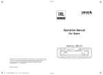
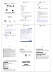
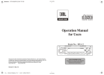
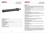
UREA/DEF AC Transfer Pump Kit
USER’S MANUAL
MODEL NUMBER
10302506 & 10302507
K. DIAGRAM AND PARTS LIST
UREA/DEF DC Transfer Pump Kit
USER’S MANUAL
1
2
3
4
5
6
7
No.
Description
8
Qty
No.
1
Nozzle
1
5
O-ring
2
2
Hose clamp
3
6
Pump
1
3
Delivery hose
1
7
Nut
2
4
Hose tail
2
8
Suction hose
1
PROBLEM
The Motor is not turning
The motor turns slowly when starting
POSSIBLE CAUSE
Lack of electric power
Motor Problems
Low voltage in the electric power line
Low level in the suction tank
Filter clogged
Excessive suction pressure
Low or no flow rate
Description
Qty
CORRECTIVE ACTION
Check the electrical connecting
Contact the Service Department
Bring the voltage back within the anticipated limits
Refill the tank
Clean the filte
Lower the pump with respect to the level of the tank
or increase the cross-section of the tubing
High loss of head in the delivery circuit (working with
Use shorter tubing or of greater diameter
the by-pass open)
By-pass valve blocked
Dismantle the valve, clean and/or replace it.
Air entering the pump or the suction tubing
Check the seals of the connections
A narrowing in the suction tubing
Use tubing suitable for working under suction
pressure
Low rotation speed
Check the voltage at the pump. Adjust the voltage
and/or use cables of greater cross-section
The suction tubing is resting on the bottom of the
Raise the tubing
tank
Cavitation occurring
Reduce suction pressure
Increased pump noise
Leakage from the pump body
Irregular functioning of the by-pass
Diaphragm damaged
3 of 3
WARNING:
Read carefully and understand all INSTRUCTIONS before operating.
Failure to follow the safety rules and other basic safety precautions may result in serious
personal injury.
MODEL NUMBER: 10302506, 10302507
Dispense fluid until the air is purged from the by-pass
system
Check and replace the diaphragm
REV 02/27/14
UREA/DEF AC Transfer Pump Kit
USER’S MANUAL
UREA/DEF AC Transfer Pump Kit
USER’S MANUAL
MODEL NUMBER
10302506 & 10302507
MODEL NUMBER
10302506 & 10302507
ATTENTION!
A. MACHINE DESCRIPTION
THE MOTORS ARE NOT OF AN ANTI-EXPLOSIVE TYPE. Do not install them where inflammable vapours can be present.
E3. CONNECTING
• Before connection, make sure that the tubing and the suction tank are free of dirt and thread residue that could damage the pump and
its accessories.
• Do not use conical threaded joints that could damage the threaded pump openings if excessively tightened.
Step 1: SUCTION HOSE:
- Connect the 1.5M Suction hose by the Hose tail (#8) and Clamp (#12) to the inlet of the pump.
Step 2: DELIVERY HOSE:
- Connect the 6M Delivery hose by the Hose tail (#8) and Clamp (#12) to the outlet of the pump or the flow meter.
Step 3: FLOW METER (Optional):
- Connect the flow meter by the Elbow (#9) to the outlet of the pump.
Step 4: NOZZLE
- Connect the dispensing nozzle by the Clamp (#12) to the delivery hose.
E4. DISPENSING
After installation the completed pump system as picture indicated, connect the power supply, start dispensing.
PUMP: Self-priming, volumetric, diaphragm pump, equipped with by-pass valve.
MOTOR: Asynchronous motor, single-phase, 2 pole, closed type (protection class IP55 in conformance with EN 60034-5-86 regulations)
self-ventilated.
B. TECHNICAL DATA
B1. Configuration
Item No.
Pump Model
Voltage
Suction Hose
Delivery Hose
Nozzle
Flow Meter
10302506
17550250
12V
1.5M
6M
Manual
N/A
10302507
17550253
24V
1.5M
6M
Manual
N/A
ATTENTION!
C. OPERATING CONDITIONS
It is the installer’s responsibility to use tubing with adequate characteristics.
Loosening of the connections (threaded connections, flanging, gasket seals) can cause serious ecological and safety problem.
Check all the connections after the initial installation and on a daily basis after that.
Tighten the connections, if necessary.
C1. ENVIRONMENTAL CONDITIONS
TEMPERATURE: Min. -10˚C(14˚F / Max. +60˚C(140˚F)
RELATIVE HUMIDITY: Max. 90%
ATTENTION!
F. DAILY USE
ATTENTION!
a. If using flexible tubing, attach the ends of the tubing to the tanks. In the absence of an appropriate slot, solidly grasp the delivery tube
before beginning dispensing.
b. Before starting the pump, make sure that the delivery valve is closed
(dispensing nozzle or line valve).
c. Turn the ON/OFF switch to ON. The by-pass valve allows functioning with the delivery closed only for brief periods.
d. Open the delivery valve, solidly grasping the end of the tubing.
e. Close the delivery valve to stop dispensing.
f. When dispensing is finished, turn off the pump.
The temperature limits shown apply to the pump components and must be respected to avoid possible damage or malfunction.
C2. ELECTRICAL POWER SUPPLY
1. During installation and maintenance, make sure that the electric supply lines are not live.
2. Always turn off the switch before supplying electrical power.
3. Check the correct rotation direction of the DC pump. If it is inverted, check the polarity of the connection cable.
a) RED cable: positive pole (+)
b) BLACK cable: negative pole (-)
Power from lines with values outside the indicated limits can damage the electrical components.
C3. WORKING CYCLE
1. Extreme operating conditions with working cycles longer than 30 minutes can cause the motor temperature to rise, thus damaging the
motor itself.
2. Each 30-minute working cycle should always be followed by a 30-minute power-off cooling phase.
3. MAXIMUM BY-PASSING TIME: 3 MINUTES.
4. DO NOT RUN DRY OVER 30 SECONDS.
ATTENTION!
Functioning under by-pass conditions is only allowed for brief periods of time (2-3minutes maximum).
C4. FLUIDS PERMITTED
PERMITTED
• Chemical products: Urea, weak acid & weak alkaline fluid etc.
• Water
D. MOVING AND TRANSPORT
Given the limited weight and size of the pumps (see overall dimensions), moving the pumps does not require the use of lifting devices.
The pumps were carefully packed before shipment. Check the packing material on delivery and store in the dry place.
E. INSTALLATION
E1. DISPOSING OF THE PACKING MATERIAL
The packing material does not require special precautions, not being in any way dangerous or polluting.
Refer to local regulations for its disposal.
E2. PRELIMINARY INSPECTION
• Check that the machine has not suffered any damage during transport or storage.
• Clean the inlet and outlet openings, removing any dust or residual packing material.
• Make sure that the motor shaft turns freely.
• Check that the electrical specifications correspond to those shown on the identification plate.
ATTENTION!
Function with the delivery closed is only allowed for brief periods (2-3 minutes maximum).
After using, make sure the pump is turned off.
G. PROBLEMS AND SOLUTIONS
H. MAINTENANCE
All models are designed and constructed to require a minimum of maintenance.
In any case always bear in mind the following basic recommendations for a good functioning of the pump:
- On a weekly basis, check that the tubing joints have not loosened, to avoid any leakage.
- On a monthly basis, check the pump body and keep it clean of any impurities.
- On a weekly basis, check and keep clean the line suction filter.
- On a monthly basis, check that the electric power supply cables are in good condition.
I. NOISE LEVEL
Under normal working conditions the noise emission from all models does not exceed the valve of 80 db at a distance of 1 meter from
the electric pump.
J. DISPOSING OF CONTAMINATED MATERIALS
In the event of maintenance or demolition of the machine, do not disperse contaminated parts into theenvironment.
Refer to local regulations for their proper disposal.
1 of 3
Size: 145x210mm
2 of 3
REV 02/27/14