1
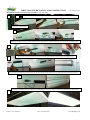
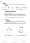
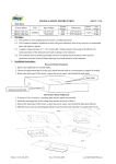
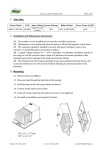
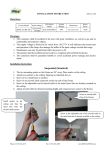
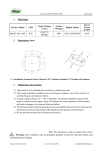
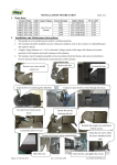
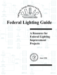
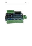
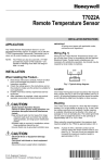
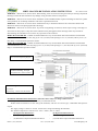
MHTL-MAGNT8-RK INSTALLATION INSTRUCTION
Rev. Date 8/1/2014
WARNING – Risk of fire or electric shock. When drilling, check for enclosed wiring and other pre-existing components.
Drilling to install the LED retrofit kit may damage wiring and other electrical components.
WARNING – Risk of fire or electric shock. Installation of the LED Retrofit Kit requires knowledge of electrical systems.
If not qualified, do not attempt installation and contact a qualified electrician.
WARNING – Risk of fire or electric shock. Install this kit only in luminaires that have the construction features and
dimensions shown in the photographs and/or drawings.
WARNING – Risk of fire or electric shock. To prevent wiring damage or abrasion, do not expose wiring to the edges of
sheet metal or sharp objects. Only those holes indicated in the photographs and/or drawings below may be made or
altered during this installation. Do not leave any open holes in the enclosure.
MHTL-MAGNT8-RK-2FT - Suitable for field installation in any recessed linear fluorescent luminaire with nominal
overall dimensions 22-3/4” (577 mm) long by 22-1/4” (565 mm) wide tapering to 16-1/4” (414 mm) wide by 2-7/8” (73
mm) deep; or with minimum equivalent volume.
MHTL-MAGNT8-RK-4FT - Suitable for field installation in any recessed linear fluorescent luminaire with nominal
overall dimensions 47-1/2” (1207 mm) long by 10-1/4” (27 mm) wide tapering to 5” (127 mm) wide by 4-1/4” (108 mm)
deep; or with minimum equivalent volume.
Two or Three Lamps Wiring Diagram
Continuous Dimming – DC Input
(Compatible with 0-10VDC Dimmers)
Bi-level Dimming – External Resistor (Rx)
For Example:
60% Dimming – Connect a 30k Ohm Resistor
Installation and Maintenance Instruction: (The below data is subject to change without notice)
-
This product is to be installed and serviced by a certified electrician.
-
Product shall be installed in an area with good ventilation, and clear of corrosive gas, combustible and explosive
objects.
-
The supply voltage is 120Vac to 277Vac. and incorrect voltage will damage the luminaire.
-
The ambient temperature is allowed to be -4ºF to +104ºF (-20ºC to +40ºC).
4ft. Replacement Kit Part List:
2ft. Replacement Kit Part List:
-
(2x/3x) 4ft Magnetic LED PCBs
-
(2x/3x) 2ft Magnetic LED PCBs
-
(1x) Dual/Three Output Dimmable LED Driver
-
(1x) Dual/Three Output Dimmable LED Driver
Phone # (718) 524-4370
Fax # (718) 524-4390
www.mhtlighting.com
MHTL-MAGNT8-RK INSTALLATION INSTRUCTION
Rev. Date 8/1/2014
Installation Procedures for Fluorescent Troffers: (1x4, 2x2, 2x4)
1
2
Unhook the lens latch and open the lens. Remove the existing T5/T8/T12 fluorescent lamps and mid panel.
Shut OFF the Circuit Breaker
3
Disconnect the input connectors, cut all unwanted wires (Existing lamp bases will not be used) and remove the existing fluorescent ballast.
4
Attach quick connecter to the input of the LED Driver and secure LED Driver onto the fixture with original screws.
5
Place magnetic LED PCBs into the fixture. Secure the ends of each PCB with self-drilling screws (if needed) and connect PCBs to LED driver.
6
Connect power to LED Driver, put mid panel back (avoid damaging wires), close fixture lens, turn on circuit breaker and light the fixture.
7
Phone # (718) 524-4370
Fax # (718) 524-4390
www.mhtlighting.com