1
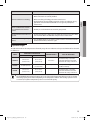
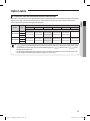
QUESTIONS OR COMMENTS?
COUNTRY
CALL
OR VISIT US ONLINE AT
CANADA
1-800-SAMSUNG(726-7864)
www.samsung.com
MEXICO
01-800-SAMSUNG(726-7864)
www.samsung.com
U.S.A
1-800-SAMSUNG(726-7864)
www.samsung.com
Big Duct_IBIM_E_33766-3.indd 38
2012-01-13 오후 9:40:35
Duct Type Series
BIG duct : ND✴✴✴HH✴✴✴
Air Conditioner
user & installation manual
imagine the possibilities
Thank you for purchasing this Samsung product.
To receive more complete service, please
register your product at
www.samsung.com/register
E F DB98-33766A(3)
Big Duct_IBIM_E_33766-3.indd 39
2012-01-13 오후 9:40:35
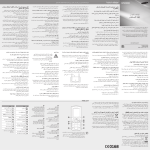
Features of your new air conditioner
Cool Summer Offer
On those hot sweltering summer days and long restless nights, there is no better escape from the heat than the cool
comforts of home. Your new air conditioner brings an end to exhausting hot summer days and lets you rest. This summer,
beat the heat with your own air conditioner.
Cost Efficient System
Your new air conditioner not only provides maximum cooling power in the summer, but can also be an efficient heating
method in the winter with the advanced “Heat pump” system. This technology is up to 300% more efficient than electrical
heating, so you can further reduce its running cost. Now, meet year-round needs with one air conditioner.
Flexible installation
Duct type air conditioner is designed to be slimmer and offers different solutions for any shape room allowing for specific
air flow requirements. Also, the air intake can be set up on either the bottom or rear of the unit, so there is more flexibility in
installation.
2
Big Duct_IBIM_E_33766-3.indd 2
2012-01-13 오후 9:40:22
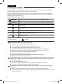
Contents
USING PARTS
ENGLISH
Safety precautions . . . . . . . . . . . . . . . . . . . . . . . . . . . . . . . . . . . . . . . . . . . . . . . . . . . . . . . . . . . . . . . . . . . . . . . . . . . . . . . . . . . . . . . . . . . . . . . . . . . . . . . 4
Viewing your air conditioner . . . . . . . . . . . . . . . . . . . . . . . . . . . . . . . . . . . . . . . . . . . . . . . . . . . . . . . . . . . . . . . . . . . . . . . . . . . . . . . . . . . . . . . . . . . . . . 8
Using your air conditioner . . . . . . . . . . . . . . . . . . . . . . . . . . . . . . . . . . . . . . . . . . . . . . . . . . . . . . . . . . . . . . . . . . . . . . . . . . . . . . . . . . . . . . . . . . . . . . . . 9
Cleaning and maintaining the air conditioner . . . . . . . . . . . . . . . . . . . . . . . . . . . . . . . . . . . . . . . . . . . . . . . . . . . . . . . . . . . . . . . . . . . . . . . . . . . 10
Appendix . . . . . . . . . . . . . . . . . . . . . . . . . . . . . . . . . . . . . . . . . . . . . . . . . . . . . . . . . . . . . . . . . . . . . . . . . . . . . . . . . . . . . . . . . . . . . . . . . . . . . . . . . . . . . . 12
INSTALLATION PARTS
Safety precautions . . . . . . . . . . . . . . . . . . . . . . . . . . . . . . . . . . . . . . . . . . . . . . . . . . . . . . . . . . . . . . . . . . . . . . . . . . . . . . . . . . . . . . . . . . . . . . . . . . . . . 14
Accessories . . . . . . . . . . . . . . . . . . . . . . . . . . . . . . . . . . . . . . . . . . . . . . . . . . . . . . . . . . . . . . . . . . . . . . . . . . . . . . . . . . . . . . . . . . . . . . . . . . . . . . . . . . . . . 16
Selecting the installation location . . . . . . . . . . . . . . . . . . . . . . . . . . . . . . . . . . . . . . . . . . . . . . . . . . . . . . . . . . . . . . . . . . . . . . . . . . . . . . . . . . . . . . 16
Indoor unit installation . . . . . . . . . . . . . . . . . . . . . . . . . . . . . . . . . . . . . . . . . . . . . . . . . . . . . . . . . . . . . . . . . . . . . . . . . . . . . . . . . . . . . . . . . . . . . . . . . 19
Purging the unit . . . . . . . . . . . . . . . . . . . . . . . . . . . . . . . . . . . . . . . . . . . . . . . . . . . . . . . . . . . . . . . . . . . . . . . . . . . . . . . . . . . . . . . . . . . . . . . . . . . . . . . . 20
Connecting the refrigerant pipe . . . . . . . . . . . . . . . . . . . . . . . . . . . . . . . . . . . . . . . . . . . . . . . . . . . . . . . . . . . . . . . . . . . . . . . . . . . . . . . . . . . . . . . . 20
Cutting/Flaring the pipes . . . . . . . . . . . . . . . . . . . . . . . . . . . . . . . . . . . . . . . . . . . . . . . . . . . . . . . . . . . . . . . . . . . . . . . . . . . . . . . . . . . . . . . . . . . . . . . 21
Performing leak test & insulation . . . . . . . . . . . . . . . . . . . . . . . . . . . . . . . . . . . . . . . . . . . . . . . . . . . . . . . . . . . . . . . . . . . . . . . . . . . . . . . . . . . . . . . 22
Drain pipe and drain hose installation . . . . . . . . . . . . . . . . . . . . . . . . . . . . . . . . . . . . . . . . . . . . . . . . . . . . . . . . . . . . . . . . . . . . . . . . . . . . . . . . . . 24
Wiring work . . . . . . . . . . . . . . . . . . . . . . . . . . . . . . . . . . . . . . . . . . . . . . . . . . . . . . . . . . . . . . . . . . . . . . . . . . . . . . . . . . . . . . . . . . . . . . . . . . . . . . . . . . . . 28
Indoor unit setting . . . . . . . . . . . . . . . . . . . . . . . . . . . . . . . . . . . . . . . . . . . . . . . . . . . . . . . . . . . . . . . . . . . . . . . . . . . . . . . . . . . . . . . . . . . . . . . . . . . . . 32
Additional functions . . . . . . . . . . . . . . . . . . . . . . . . . . . . . . . . . . . . . . . . . . . . . . . . . . . . . . . . . . . . . . . . . . . . . . . . . . . . . . . . . . . . . . . . . . . . . . . . . . . . 33
Final checks and user tips . . . . . . . . . . . . . . . . . . . . . . . . . . . . . . . . . . . . . . . . . . . . . . . . . . . . . . . . . . . . . . . . . . . . . . . . . . . . . . . . . . . . . . . . . . . . . . . 34
Troubleshooting . . . . . . . . . . . . . . . . . . . . . . . . . . . . . . . . . . . . . . . . . . . . . . . . . . . . . . . . . . . . . . . . . . . . . . . . . . . . . . . . . . . . . . . . . . . . . . . . . . . . . . . 35
Option table . . . . . . . . . . . . . . . . . . . . . . . . . . . . . . . . . . . . . . . . . . . . . . . . . . . . . . . . . . . . . . . . . . . . . . . . . . . . . . . . . . . . . . . . . . . . . . . . . . . . . . . . . . . 37
3
Big Duct_IBIM_E_33766-3.indd 3
2012-01-13 오후 9:40:22
USING PARTS
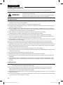
Safety precautions
Before using your new air conditioner, please read this manual thoroughly to ensure that you know how to safely and
efficiently operate the extensive features and functions of your new appliance.
Because the following operating instructions cover various models, the characteristics of your air conditioner may differ
slightly from those described in this manual. If you have any questions, call your nearest contact center or find help and
information online at www.samsung.com.
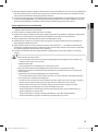
Important safety symbols and precautions :
WARNING
Hazards or unsafe practices that may result in severe personal injury or death.
CAUTION
Hazards or unsafe practices that may result in minor personal injury or property damage.
Follow directions.
Do NOT attempt.
Make sure the machine is grounded to prevent electric shock.
Unplug the power plug from the wall socket.
Do NOT disassemble.
FOR INSTALLATION
WARNING
Use the power line with the power specifications of the product or higher and use the power line for this
appliance only. In addition, do not use an extension line.
XXExtending the power line may result in electric shock or fire.
XXDo not use an electric transformer. It may result in electric shock or fire.
XXIf the voltage/frequency/rated current condition is different, it may cause fire.
The installation of this appliance must be performed by a qualified technician or service company.
XXFailing to do so may result in electric shock, fire, explosion, problems with the product, or injury.
Install a switch and circuit breaker dedicated to the air conditioner.
XXFailing to do so may result in electric shock or fire.
Fix the outdoor unit firmly so that the electric part of the outdoor unit is not exposed.
XXFailing to do so may result in electric shock or fire.
Do not install this appliance near a heater, inflammable material. Do not install this appliance in a humid, oily or
dusty location, in a location exposed to direct sunlight and water (rain drops). Do not install this appliance in a
location where gas may leak.
XXThis may result in electric shock or fire.
Never install the outdoor unit in a location such as on a high external wall where it could fall.
XXIf the outdoor unit falls, it may result in injury, death or property damage.
This appliance must be properly grounded. Do not ground the appliance to a gas pipe, plastic water pipe, or
telephone line.
XXFailure to do so may result in electric shock, fire, an explosion, or other problems with the product.
XXNever plug the power cord into a socket that is not grounded correctly and make sure that it is in accordance with
local and national codes.
4
Big Duct_IBIM_E_33766-3.indd 4
2012-01-13 오후 9:40:22
FOR INSTALLATION
CAUTION
FOR POWER SUPPLY
ENGLISH
Install your appliance on a level and hard floor that can support its weight.
XXFailing to do so may result in abnormal vibrations, noise, or problems with the product.
Install the draining hose properly so that water is drained correctly.
XXFailing to do so may result in water overflowing and property damage.
When installing the outdoor unit, make sure to connect the draining hose so that draining is performed
correctly.
XXThe water generated during the heating operation by the outdoor unit may overflow and result in property
damage. In particular, in winter, if a block of ice falls, it may result in injury, death or property damage.
WARNING
When the circuit breaker is damaged, contact your nearest service center.
Do not pull or excessively bend the power line. Do not twist or tie the power line. Do not hook the power line
over a metal object, place a heavy object on the power line, insert the power line between objects, or push the
power line into the space behind the appliance.
XXThis may result in electric shock or fire.
FOR POWER SUPPLY
CAUTION
When not using the air conditioner for a long period of time or during a thunder/lightning storm, cut the power
at the circuit breaker.
XXFailing to do so may result in electric shock or fire.
FOR USING
WARNING
If the appliance is flooded, please contact your nearest service center.
XXFailing to do so may result in electric shock or fire.
If the appliance generates a strange noise, a burning smell or smoke, unplug the power plug immediately and
contact your nearest service center.
XXFailing to do so may result in electric shock or fire.
In the event of a gas leak (such as propane gas, LP gas, etc.), ventilate immediately without touching the power
line.
Do not touch the appliance or power line.
XXDo not use a ventilating fan.
XXA spark may result in an explosion or fire.
To reinstall the air conditioner, please contact your nearest service center.
XXFailing to do so may result in problems with the product, water leakage, electric shock, or fire.
XXA delivery service for the product is not provided. If you reinstall the product in another location, additional
construction expenses and an installation fee will be charged.
XXEspecially, when you wish to install the product in an unusual location such as in an industrial area or near the
seaside where it is exposed to the salt in the air, please contact your nearest service center.
5
Big Duct_IBIM_E_33766-3.indd 5
2012-01-13 오후 9:40:23
Safety precautions
FOR USING
WARNING
Do not touch the circuit breaker with wet hands.
XXThis may result in electric shock.
Do not strike or pull the air conditioner with excessive force.
XXThis may result in fire, injury, or problems with the product.
Do not place an object near the outdoor unit that allows children to climb onto the machine.
XXThis may result in children seriously injuring themselves.
Do not turn the air conditioner off with the circuit breaker while it is operating.
XXTurning the air conditioner off and then on again with the circuit breaker may cause a spark and result in electric
shock or fire.
After unpacking the air conditioner, keep all packaging materials well out of the reach of children, as packaging
materials can be dangerous to children.
XXIf a child places a bag over its head, it may result in suffocation.
Do not insert your fingers or foreign substances into the outlet when the air conditioner is operating or the front
panel is closing.
XXTake special care that children do not injure themselves by inserting their fingers into the product.
Do not touch the front panel with your hands or fingers during the heating operation.
XXThis may result in electric shock or burns.
Do not insert your fingers or foreign substances into the air inlet/outlet of the air conditioner.
XXTake special care that children do not injure themselves by inserting their fingers into the product.
Do not use this air conditioner for long periods of time in badly ventilated locations or near infirm people.
XXSince this may be dangerous due to a lack of oxygen, open a window at least once an hour.
If any foreign substance such as water has entered the appliance, cut the power by unplugging the power plug
and turning the circuit breaker off and then contact your nearest service center.
XXFailing to do so may result in electric shock or fire.
Do not attempt to repair, disassemble, or modify the appliance yourself.
XXDo not use any fuse (such as copper, steel wire, etc.)other than the standard fuse.
XXFailing to do so may result in electric shock, fire, problems with the product, or injury.
FOR USING
CAUTION
Do not place objects or devices under the indoor unit.
XXWater dripping from the indoor unit may result in fire or property damage.
Check that the installation frame of the outdoor unit is not broken at least once a year.
XXFailing to do so may result in injury, death or property damage.
Max current is measured according to IEC standard for safety and current is measured according to ISO standard
for energy efficiency.
6
Big Duct_IBIM_E_33766-3.indd 6
2012-01-13 오후 9:40:23
FOR CLEANING
ENGLISH
Do not stand on top of the appliance or place objects (such as laundry, lighted candles, lighted cigarettes,
dishes, chemicals, metal objects, etc.) on the appliance.
XXThis may result in electric shock, fire, problems with the product, or injury.
Do not operate the appliance with wet hands.
XXThis may result in electric shock.
Do not spray volatile material such as insecticide onto the surface of the appliance.
XXAs well as being harmful to humans, it may also result in electric shock, fire or problems with the product.
Do not drink the water from the air conditioner.
XXThe water may be harmful to humans.
Do not apply a strong impact to the remote controller and do not disassemble the remote controller.
Do not touch the pipes connected with the product.
XXThis may result in burns or injury.
Do not use this air conditioner to preserve precision equipment, food, animals, plants or cosmetics, or for any
other unusual purposes.
XXThis may result in property damage.
Avoid directly exposing humans, animals or plants from the air flow from the air conditioner for long periods of
time.
XXThis may result in harm to humans, animals or plants.
This appliance is not intended for use by persons (including children) with reduced physical, sensory or mental
capabilities, or lack of experience and knowledge, unless they have been given supervision or instruction
concerning use of the appliance by a person responsible for their safety. Children should be supervised to
ensure that they do not play with the appliance.
WARNING
Do not clean the appliance by spraying water directly onto it. Do not use benzene, thinner or alcohol to clean
the appliance.
XXThis may result in discoloration, deformation, damage, electric shock or fire.
Before cleaning or performing maintenance, unplug the air conditioner from the wall socket and wait until the
fan stops.
XXFailing to do so may result in electric shock or fire.
FOR CLEANING
CAUTION
Take care when cleaning the surface of the heat exchanger of the outdoor unit since it has sharp edges.
XXTo avoid cutting your fingers, wear thick cotton gloves when cleaning it.
Do not clean the inside of the air conditioner by yourself.
XXFor cleaning inside the appliance, contact your nearest service center.
XXWhen cleaning the internal filter, refer to the descriptions in the ‘Cleaning and maintaining the air conditioner’
section.
XXFailure to do may result in damage, electric shock or fire.
7
Big Duct_IBIM_E_33766-3.indd 7
2012-01-13 오후 9:40:23
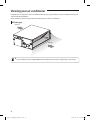
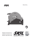
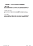
Viewing your air conditioner
Congratulations on the purchase of the air conditioner. We hope you enjoy the features of your air conditioner and stay cool
or warm with optimal efficiency.
Please read the user manual to get started and to make the best use of the air conditioner.
BIG duct type
Air Outlet
Air intake
NOTE
• Your air conditioner may look slightly different from the illustration shown above depending on your model.
8
Big Duct_IBIM_E_33766-3.indd 8
2012-01-13 오후 9:40:23
Using your air conditioner
Tips on using your air conditioner
Here are some tips that you would follow when using your air conditioner.
RECOMMENDATION
Cooling
• If current outside temperatures are much higher than the selected indoor temperature,
it may take time to bring the inner temperature to the desired coolness.
• Avoid drastically turning down the temperature. Energy is wasted and the room does
not cool faster.
Heating
• Since the air conditioner heats the room by taking heat energy from outdoor air, the
heating capacity may decrease when outdoor temperatures are extremely low. If you
feel the air conditioner insufficiently heats, using an additional heating appliance in
combination with the air conditioner is recommended.
Frost & De-ice
• When the air conditioner runs in Heat mode, due to temperature difference between
the unit and the outside air, frost will form.
• If this happens:
-- The air conditioner stops heating.
-- The air conditioner will operate automatically in De-ice mode for 10 minutes.
-- The steam produced on the outdoor unit in De-ice mode is safe.
• No intervention is required; after about 10 minutes, the air conditioner operates again
normally.
NOTE
• The unit will not operate when it starts to de-ice.
Fan
• Fan may not operate for about 3~5 minutes at the beginning to prevent any cold blasts
while the air conditioner is warming up.
High indoor/outdoor
temperatures
• If both indoor and outdoor temperatures are high and the air conditioner is running in
Heat mode, the outdoor unit’s fan and compressor may stop at times. This is normal;
wait until the air conditioner turns on again.
Power failure
• If a power failure occurs during the operation of the air conditioner, the operating
immediately stops and unit will be off. When power returns, the air conditioner will run
automatically.
Protection mechanism
ENGLISH
TOPIC
• If the air conditioner has just been turned on after operation stops or being plugged
in, cool/warm air does not come out for 3 minutes to protect the compressor of the
outdoor unit.
9
Big Duct_IBIM_E_33766-3.indd 9
2012-01-13 오후 9:40:23
Cleaning and maintaining the air conditioner
Maintaining your air conditioner
If the air conditioner will not be used for an extended period of time, dry the air conditioner to maintain it in best condition.
1. Dry the air conditioner thoroughly by operating in Fan mode for 3 to 4 hours and disconnect the power plug. There may
be internal damage if moisture is left in components.
2. Before using the air conditioner again, dry the inner components of the air conditioner again by running in Fan mode for
3 to 4 hours. This helps remove odors which may have generated from dampness.
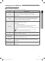
Periodical checks
Refer to the following chart to maintain the air conditioner properly.
Type
Description
Clean the air filter (1)
Indoor unit
Monthly
Every 4
months
●
Clean the condensate drain pan (2)
●
Thoroughly clean the heat exchanger (2)
●
Clean the condensate drain pipe (2)
●
Replace the remote control batteries (1)
Clean the heat exchanger on the outside of the unit (2)
Outdoor unit
NOTE
Once a year
●
●
Clean the heat exchanger on the inside of the unit (2)
●
Clean the electric components with jets of air (2)
●
Verify that all the electric components are firmly
tightened (2)
●
Clean the fan (2)
●
Verify that all the fan assembly is firmly tightened (2)
●
Clean the condensate drain pan (2)
●
• The checks and maintenance operations described are essential to guarantee the efficiency of the air
conditioner. The frequency of these operations varies according to the characteristics of the area, the amount of
dust, etc.
1) The described operations should be performed more frequently if the area of installation is very dusty.
2) These operations must always be performed by qualified personnel. For more detailed information, see the
Installation Manual.
10
Big Duct_IBIM_E_33766-3.indd 10
2012-01-13 오후 9:40:23
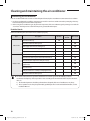
Internal protections via the unit control system
This internal protection operates if an internal fault occurs in the air conditioner.
Type
Description
The internal fan will be off to against cold air when the heat pump is heating.
De-ice cycle
The internal fan will be off to against cold air when the heat pump is heating.
Anti-protection of internal
battery
The compressor will be off to protect internal battery when the air conditioner
operates in Cool mode.
Protect compressor
NOTE
ENGLISH
Against cold air
The air conditioner does not start operating immediately to protect the compressor of
the outdoor unit after it has been started.
• If the heat pump is operating in Heat mode, De-ice cycle is actuated to remove frost from an outdoor unit that
may have deposited at low temperatures.
• The internal fan is switched off automatically and restarted only after the de-ice cycle is completed.
11
Big Duct_IBIM_E_33766-3.indd 11
2012-01-13 오후 9:40:24
Appendix
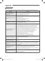
Troubleshooting
Refer to the following chart if the air conditioner operates abnormally. This may save time and unnecessary expenses.
PROBLEM
SOLUTION
The air conditioner does not
operate immediately after it has
been restarted.
• Because of the protective mechanism, the appliance does not start operating
immediately to keep the unit from overloading.
The air conditioner will start in 3 minutes.
The air conditioner does not work
at all.
• Check that the power plug is properly connected. Insert the power plug into the
wall socket correctly.
• Check if the circuit breaker is switched off.
• Check if there is a power failure.
• Check your fuse. Make sure it is not blown out.
The temperature does not change.
• Check if you selected Fan mode.
Press the Mode button on the remote control to select another mode.
The cool (warm) air does not come
out of the air conditioner.
• Check if the set temperature is higher (lower) than the current temperature. Press
the Temperature button on the remote control to change the set temperature.
Press the Temperature button to decrease or increase the temperature.
• Check if the air filter is blocked by dirt. Clean the air filter every two weeks.
• Check if the air conditioner has just been turned on. If so, wait 3 minutes. Cool air
does not come out to protect the compressor of the outdoor unit.
• Check if the air conditioner is installed in a place with a direct exposure to
sunlight. Hang curtains on windows to boost cooling efficiency.
• Check if the cover or any obstacle is not near the outdoor unit.
• Check if the refrigerant pipe is too long.
• Check if the air conditioner is only available in Cool mode.
• Check if the remote control is only available for cooling model.
The fan speed does not change.
• Check if you selected Auto or Dry mode.
The air conditioner automatically adjusts the fan speed to Auto in Auto/Dry
mode.
Timer function does not set.
• Check if you press the Power button on the remote control after you have set
the time.
Odors permeate in the room during
operation.
• Check if the appliance is running in a smoky area or if there is a smell entering
from outside. Operate the air conditioner in Fan mode or open the windows to
air out the room.
The air conditioner makes a
bubbling sound.
• A bubbling sound may be heard when the refrigerant is circulating through the
compressor. Let the air conditioner operate in a selected mode.
• When you press the Power button on the remote control, noise may be heard
from the drain pump inside the air conditioner.
Water is dripping from the air flow
blades.
• Check if the air conditioner has been cooling for an extended period of time with
the air flow blades pointed downwards. Condensation may generate due to the
difference in temperature.
12
Big Duct_IBIM_E_33766-3.indd 12
2012-01-13 오후 9:40:24
PROBLEM
SOLUTION
The air conditioner does not turn
on or off with the wired remote
control.
• Check if you set the wired remote control for group control.
The wired remote control does not
operate.
• Check if TEST indicator is displayed on the wired remote control. If so, turn off the
unit and switch off the circuit breaker. Call your nearest contact center.
The indicators of the digital display
flashes.
• Press the Power button on the remote control to turn the unit off and switch the
circuit breaker off. Then, switch it on again.
ENGLISH
Remote controller is not working.
• Check if your batteries are depleted.
• Make sure batteries are correctly installed.
• Make sure nothing is blocking your remote control sensor.
• Check that there are strong lighting apparatus near the air conditioner. Strong
light which comes from fluorescent bulbs or neon signs may interrupt the
electric waves.
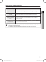
Operation ranges
The table below indicates the temperature and humidity ranges the air conditioner can be operated within. Refer to the table
for efficient use.
MODE
OPERATIONAL TEMPERATURE
INDOOR HUMIDITY
IF OUT OF CONDITIONS
INDOOR
OUTDOOR
COOLING
64˚F to 90˚F
(18˚C to 32˚C)
23˚F to 109˚F
(-5˚C to 43˚C)
80% or less
HEATING
81˚F(27˚C) or less
-40˚F to 75˚F
(-20˚C to 24˚C)
-
Internal protection triggers and the air
conditioner will stop.
DRYING
64˚F to 90˚F
(18˚C to 32˚C)
23˚F to 109˚F
(-5˚C to 43˚C)
-
Condensation may occur on the
indoor unit with risk to have either
water blow off or drops on the floor.
NOTE
Condensation may occur on the
indoor unit with risk to have either
water blow off or drops on the floor.
• The standardized temperature for heating is 45˚F(7˚C). If the outdoor temperature drops to 32˚F(0˚C) or below,
the heating capacity can be reduced depending on the temperature condition. If the cooling operation is used
at over 90˚F(32˚C)(indoor temperature), it does not cool at its full capacity.
13
Big Duct_IBIM_E_33766-3.indd 13
2012-01-13 오후 9:40:24
INSTALLATION PARTS
Safety precautions
Carefully follow the precautions listed below because they are essential to guarantee the safety of the equipment.
WARNING
• Always disconnect the air conditioner from the power supply before servicing it or
accessing its internal components.
• Verify that installation and testing operations are performed by qualified personnel.
• Verify that the air conditioner is not installed in an easily accessible area.
General information
ffCarefully read the content of this manual before installing the air conditioner and store the manual in a safe place in order
to be able to use it as reference after installation.
ffFor maximum safety, installers should always carefully read the following warnings.
ffStore the operation and installation manual in a safe location and remember to hand it over to the new owner if the air
conditioner is sold or transferred.
ffThis manual explains how to install an indoor unit with a split system with two SAMSUNG units. The use of other types
of units with different control systems may damage the units and invalidate the warranty. The manufacturer shall not be
responsible for damages arising from the use of non compliant units.
ffThe air conditioner is compliant with the requirements of the Low Voltage Directive (72/23/EEC),
the EMC Directive (89/336/EEC) and the Directive on pressurized equipment (97/23/EEC).
ffThe manufacturer shall not be responsible for damage originating from unauthorized changes or the improper
connection of electric and requirements set forth in the “Operating limits” table, included in the manual. Making such
changes or improper connections may damage the units and invalidate the warranty.
ffThe air conditioner should be used only for the applications for which it has been designed: the indoor unit is not suitable
to be installed in areas used for laundry.
ffDo not use the units if damaged. If problems occur, switch the unit off and disconnect it from the power supply.
ffIn order to prevent electric shocks, fires or injuries, always stop the unit, disable the protection switch and contact
SAMSUNG’s technical support if the unit produces smoke, if the power cable is hot or damaged or if the unit is very noisy.
ffAlways remember to inspect the unit, electric connections, refrigerant tubes and protections regularly. These operations
should be performed by qualified personnel only.
ffThe unit contains moving parts, which should always be kept out of the reach of children.
ffDo not attempt to repair, move, alter or reinstall the unit. If performed by unauthorized personnel, these operations may
cause electric shocks or fires.
ffDo not place containers with liquids or other objects on the unit.
ffAll the materials used for the manufacture and packaging of the air conditioner are recyclable.
ffThe packing material and exhaust batteries of the remote controller(optional) must be disposed of in accordance with
current laws.
ffThe air conditioner contains a refrigerant that has to be disposed of as special waste. At the end of its life cycle, the air
conditioner must be disposed of in authorized centers or returned to the retailer so that it can be disposed of correctly
and safely.
Installing the unit
IMPORTANT: When installing the unit, always remember to connect first the refrigerant tubes, then the electrical lines. Always
disassemble the electric lines before the refrigerant tubes.
ffUpon receipt, inspect the product to verify that it has not been damaged during transport. If the product appears
damaged, DO NOT INSTALL it and immediately report the damage to the carrier or retailer (if the installer or the
authorized technician has collected the material from the retailer.)
ffAfter completing the installation, always carry out a functional test and provide the instructions on how to operate the air
conditioner to the user.
ffDo not use the air conditioner in environments with hazardous substances or close to equipment that release free flames
to avoid the occurrence of fires, explosions or injuries.
14
Big Duct_IBIM_E_33766-3.indd 14
2012-01-13 오후 9:40:24
ffOur units should be installed in compliance with the spaces shown in the installation manual, to ensure accessibility from
both sides and allow repairs or maintenance operations to be carried out. The unit’s components should be accessible
and easy to disassemble without endangering people and objects.
ffFor this reason, when provisions of the installation manual are not complied with, the cost required to access and repair
the units (in SAFETY CONDITIONS, as set out in prevailing regulations) with harnesses, ladders, scaffolding or any other
elevation system will NOT be considered part of the warranty and will be charged to the end customer.
ffAlways make sure that the power supply is compliant with current safety standards. Always install the air conditioner in
compliance with current local safety standards.
ffAlways verify that a suitable grounding connection is available.
ffVerify that the voltage and frequency of the power supply comply with the specifications and that the installed power is
sufficient to ensure the operation of any other domestic appliance connected to the same electric lines.
ffAlways verify that the cut-off and protection switches are suitably dimensioned.
ffVerify that the air conditioner is connected to the power supply in accordance with the instructions provided in the
wiring diagram included in the manual.
ffAlways verify that electric connections (cable entry, section of leads, protections…) are compliant with the electric
specifications and with the instructions provided in the wiring scheme. Always verify that all connections comply with
the standards applicable to the installation of air conditioners.
ffDevices disconnected from the power supply should be completely disconnected in the condition of overvoltage
category.
CAUTION
ENGLISH
Power supply line, fuse or circuit breaker
• Make sure that you earth the cables.
-- Do not connect the earth wire to the gas pipe, water pipe, lighting rod or telephone wire. If earthing is not
complete, electric shock or fire may occur.
• Install the circuit breaker.
-- If the circuit breaker is not installed, electric shock or fire may occur.
• Make sure that the condensed water dripping from the drain hose runs out properly and safely.
• Install the power cable and communication cable of the indoor and outdoor unit at least 1m away from the
electric appliance.
• Install the indoor unit away from lighting apparatus using the ballast.
-- If you use the wireless remote control, reception error may occur due to the ballast of the lighting apparatus.
• Do not install the air conditioner in following places.
-- Place where there is mineral oil or arsenic acid. Resin parts flame and the accessories may drop or water may
leak. The capacity of the heat exchanger may reduce or the air conditioner may be out of order.
-- The place where corrosive gas such as sulfurous acid gas generates from the vent pipe or air outlet.
-- The copper pipe or connection pipe may corrode and refrigerant may leak.
-- The place where there is a machine that generates electromagnetic waves. The air conditioner may not
operate normally due to control system.
-- The place where there is a danger of existing combustible gas, carbon fiber or flammable dust.
-- The place where thinner or gasoline is handled. Gas may leak and it may cause fire.
15
Big Duct_IBIM_E_33766-3.indd 15
2012-01-13 오후 9:40:24
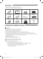
Accessories
The following accessories are supplied with the indoor unit.
The type and quantity may differ depending on the specifications.
User & Installation manual
Pattern sheet
Insulation cover pipe in
Insulation cover pipe out
Insulation pipe(A)
Insulation pipe(B)
Cable tie
Flexible hose
Clamp hose
Washer
Rubber
Sleeve
Selecting the installation location
Indoor unit
ffThere must be no obstacles near the air inlet and outlet.
ffInstall the indoor unit on a ceiling that can support its weight.
ffMaintain sufficient clearance around the indoor unit.
ffMake sure that the water dripping from the drain hose runs away correctly and safely.
ffThe indoor unit must be installed in this way, that they are out of public access. (Not touchable by the users.)
ffAfter connecting a chamber, insulate the connection part between the indoor unit and the chamber with t10 or thicker
insulation. Otherwise, there can be air leak or dew from the connection part.
ffRigid wall without vibration.
ffWhere it is not exposed to direct sunshine.
ffWhere the air filter can be removed and cleaned easily.
Space requirements for installation & service
ffConstruction standard for inspection hole.
1) In case, the ceiling is textile, inspection hole dose not need.
2) In case, the ceiling is plaster board, inspection hole depends on inside height of the ceiling.
a. Height is more than 3.28ft(1m) : Only “B” [Inspection for PBA] is applied.
b. Height is less than 3.28ft(1m) : Both “A” & ”B” are applied.
c. “A” & ”B” are inspection holes.
16
Big Duct_IBIM_E_33766-3.indd 16
2012-01-13 오후 9:40:25
ENGLISH
Unit Depth(D) + 1.96(50)
Unit : inch(mm)
Unit Width(W)
“A”=W+3.93(100)
“B”=19.65(500)
0.78(20) or more
0.78(20) or more
• You must have 0.78inch(20mm) or more space between the ceiling and the bottom of indoor unit. Otherwise, the noise
from the vibration of indoor unit may bother the user. When the ceiling is under construction, the hole for check-up
must be made to take service, clean and repair the unit.
• It is possible to install the unit at an height of between 7.54ft~8.20ft(2.2~2.5m) from the ground, if the unit has a duct
with a well defined lenght [11.81inch(300mm)], to avoid fan motor blower contact.
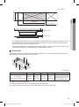
Insulation guide
If the humidity is over 80%, it is required to add 0.4(10mm) polyethylene foam or other similar insulation to the indoor unit
when installing belt or pipe type indoor unit on the ceiling.
D
B
Back
Front
A
Indoor unit
22.0~28.0kW
[48.8x18.5x41.0(1240x470x1040)]
C
Unit : inch(mm)
A
48.8x41.0
(1240x1040)
B
48.8x41.0
(1240x1040)
C
18.5x41.0
(470x1040)
D
Front / Back
18.5x41.0
(470x1040)
Insulate the front and back side
in proper size at the same time
when insulating the suction
duct and discharge duct.
ffThickness: more than 0.4inch(10mm)
ffInsulate the end of the pipe and some curved area by using separate insulator.
ffInsulate the discharge and suction part at the same time when you insulate connection duct.
17
Big Duct_IBIM_E_33766-3.indd 17
2012-01-13 오후 9:40:25
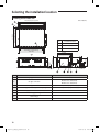
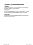
Selecting the installation location
Drawing of the indoor unit
Unit : inch(mm)
41.0(1040)
36.0(914) Suspension position
51.4(1306) Suspension position
46.8(1188) Air inlet duct flange
5.5(140)x8=44.1(1120)
34
3.9(100)x2=7.9(200)
B
3.7(93)
C
0.9(22)
D
1.1(29)
26.0(660)
25.5(647)
23.6(598)
Discharge side
15.2(385)
D
A
8.2(209)
9.3(236)
18.5(470 )
OD ø1.26(32)
1.4(35)
B C
5.5(140)x8=44.1(1120)
46.8(1188) Air outlet duct flange
48.9(1240)
A
Suction side
No.
Name
Description
1
Liquid pipe connection
ø3/8"(9.52)
2
Gas pipe connection
ND220✴✴✴ : ø3/4"(19.05)
ND280✴✴✴ : ø7/8"(22.22)
3
Drain pipe connection
VP25 [OD ø1.26(32), ID ø0.98(25)]
4
Drain pipe connection (Option drain pump)
VP25 [OD ø1.26(32), ID ø0.98(25)]
5
Power supply/Communication connection
6
Air discharge grille flange
7
Suction flange
8
Hook
3/8” or M10
18
Big Duct_IBIM_E_33766-3.indd 18
2012-01-13 오후 9:40:27
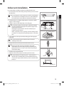
Indoor unit installation
It is recommended to install theY-joint before installing the indoor unit.
1. Place the pattern sheet on the ceiling at the spot where you want to install
the indoor unit.
• Since the diagram is made of paper, it may shrink or stretch slightly
due to temperature or humidity. For this reason, before drilling the
holes, maintain the correct dimensions between the markings.
ENGLISH
NOTE
2. Insert bolt anchors, use existing ceiling supports or construct a suitable
support as shown in figure.
3. Install the suspension bolts depending on the ceiling type.
CAUTION
• Ensure that the ceiling is strong enough to support the weight of
the indoor unit. Before hanging the unit, test the strength of each
attached suspension bolt.
• If the length of suspension bolt is more than 4.92ft(1.5m), it is
required to prevent vibration.
• If this is not possible, create an opening on the false ceiling in order
to be able to use it to perform the required operations on the indoor
unit.
Concrete
Insert
Hole in anchor
Hole in plug
Suspension bolt( 3/8” or M10)
Ceiling support
4. Screw eight nuts to the suspension bolts making space for hanging the
indoor unit.
CAUTION
• You must install the suspension bolts more than four when
installing the indoor unit.
5. Hang the indoor unit to the suspension bolts between two nuts.
NOTE
• Piping must be laid and connected inside the ceiling when
suspending the unit. If the ceiling is already constructed, lay the
piping into position for connection to the unit before placing the
unit inside the ceiling.
6. Screw the nuts to suspend the unit.
7. Adjust level of the unit by using measurement plate for all 4 sides.
NOTE
• For proper drainage of condensate, give a 1° slant to the left or
right side of the unit which will be connected with the drain hose,
as shown in the figure. Make a tilt when you wish to install the drain
pump, too.
Rubber
1°
Drain hose port
19
Big Duct_IBIM_E_33766-3.indd 19
2012-01-13 오후 9:40:27
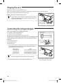
Purging the unit
On delivery, the indoor unit is loaded with inert gas.
All this gas must be purged before connecting the assembly piping. To purge the inert gas, proceed as follows.
Unscrew the pinch pipe at the end of each refrigerant pipe.
Wet cloth
Result : All inert gas escapes from the indoor unit.
NOTE
• To prevent dirt or foreign objects from getting into the pipes during
installation, do NOT remove the pinch pipe completely until you are
ready to connect the piping.
Liquid
refrigerant port
Gas refrigerant port
Welding flame
Connecting the refrigerant pipe
There are two refrigerant pipes of differing diameters :
Refrigerant oil
ffA smaller one for the liquid refrigerant
ffA larger one for the gas refrigerant
ffThe inside of copper pipe must be clean & has no dust.
The connection procedure for the refrigerant pipes varies according to the exit
position of the pipes from the indoor unit, as seen when facing the indoor in
the “A” side.
Torque wrench
ffLiquid refrigerant port
Flare nut
ffGas refrigerant port
ffDrain hose port
1. Remove the pinch pipe on the pipes and connect the assembly pipes to each
pipe, tightening the nuts, first manually and then with a torque wrench, a
spanner applying the following torque.
Outer Diameter
1/4inch(6.35 mm)
3/8inch(9.52 mm)
1/2inch(12.70 mm)
5/8inch(15.88 mm)
NOTE
Torque
10.46~12.63 ft•lb(145~175 kgf•cm)
24.02~29.36 ft•lb(333~407 kgf•cm)
36.43~44.37 ft•lb(505~615 kgf•cm)
45.45~55.48 ft•lb(630~769 kgf•cm)
Spanner
Union
A
• Must apply refrigerant oil on the flaring area to prevent a leak.
2. Be sure that there must be no crack or kink on the bended area.
❋❋ The designs and shape are subject to
change according to the model.
20
Big Duct_IBIM_E_33766-3.indd 20
2012-01-13 오후 9:40:28
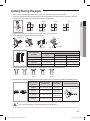
Cutting/Flaring the pipes
1. Make sure that you prepared the required tools. (pipe cutter, reamer, flaring tool and pipe holder)
2. If you want to shorten the pipe, cut it using a pipe cutter ensuring that the cut edge remains at 90° with the side of the
pipe. There are some examples of correctly and incorrectly cut edges below.
Rough
Burr
ENGLISH
Oblique
3. To prevent a gas leak, remove all burrs at the cut edge of the pipe using a reamer.
4. Carry out flaring work using flaring tool as shown below.
A
Flaring tool
York
Die
Die
Clutch type
Wing nut type
Outer diameter D
[inch(mm)]
Copper pipe
Copper pipe
Flare nut
A [inch(mm)]
Conventional flare tool
Flare tool for R410A
clutch type
Clutch type
Wing nut type
1/4(6.35)
0~0.020(0~0.5)
0.039~0.059(1.0~1.5)
0.059~0.079(1.5~2.0)
3/8(9.52)
0~0.020(0~0.5)
0.039~0.059(1.0~1.5)
0.059~0.079(1.5~2.0)
1/2(12.70)
0~0.020(0~0.5)
0.039~0.059(1.0~1.5)
0.059~0.079(1.5~2.0)
5/8(15.88)
0~0.020(0~0.5)
0.039~0.059(1.0~1.5)
0.059~0.079(1.5~2.0)
5. Check if you flared the pipe correctly. There are some examples of incorrectly flared pipes below.
Correct
Inclined
Damaged
Surface
Cracked
Uneven
Thickness
6. Align the pipes and tighten the flare nuts first manually and then with a torque wrench, applying the following torque.
CAUTION
Flare dimension
[inch(mm)]
1/4(6.35)
10.46~12.63 (145~175)
0.34~0.36
(8.70~9.10)
3/8(9.52)
24.02~29.36 (333~407)
0.50~0.52
(12.80~13.20)
1/2(12.70)
36.43~44.37 (505~615)
0.64~0.65
(16.20~16.60)
5/8(15.88)
45.45~55.48 (630~769)
0.76~0.78
(19.30~19.70)
Flare shape [inch(mm)]
45° ± 2°
Connection Torque
[ft•lb(kgf•cm)]
90° ±2°
Outer diameter
[inch(mm)]
R 0.016~0.031
(0.4~0.8)
• In case of needing brazing, you must work with Nitrogen gas blowing.
21
Big Duct_IBIM_E_33766-3.indd 21
2012-01-13 오후 9:40:28
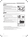
Performing leak test & insulation
Leak test
LEAK TEST WITH NITROGEN (before opening valves)
In order to detect basic refrigerant leaks, before recreating the vacuum and
recirculating the R410A, it’s responsible of installer to pressurize the whole system
with nitrogen (using a pressure regulator) at a pressure above 4.1MPa (gauge).
Leak check
LEAK TEST WITH R410A (after opening valves)
Before opening valves, discharge all the nitrogen into the system and create
vacuum. After opening valves check leaks using a leak detector for refrigerant
R410A.
CAUTION
• Discharge all the nitrogen to create a vacuum and charge the system.
Insulation
Once you have checked that there are no leaks in the system, you can insulate the piping and hose.
1. To avoid condensation problems, place T13.0 or thicker Acrylonitrile Butadien
Rubber separately around each refrigerant pipe.
NOTE
No gap
• Always make the seam of pipes face upwards.
2. Wind insulating tape around the pipes and drain hose avoiding to compress
the insulation too much.
3. Finish wrapping insulating tape around the rest of the pipes leading to the
outdoor unit.
4. The pipes and electrical cables connecting the indoor unit with the outdoor
unit must be fixed to the wall with suitable ducts.
CAUTION
• All refrigerant connection must be accessible, in order to permit
either unit maintenance or removing it completely.
NBR(T13.0 or thicker)
Insulation cover pipe
Insulation pipe
Indoor unit
Be sure to overlap
the insulation
CAUTION
• Must fit tightly against
body without any gap.
5. Select the insulation of the refrigerant pipe.
ffInsulate the gas side and liquid side pipe referring to the thickness according to the pipe size.
ffIndoor temperature of 86°F(30°C) and humidity of 85% is the stan dard condition.
If installing in a high humidity condition, use one grade thicker insulator by referring to the table below.
If installing in an unfavorable conditions, use thicker one.
ffInsulator’s heat-resistance temperature should be more than 248°F(120°C).
22
Big Duct_IBIM_E_33766-3.indd 22
2012-01-13 오후 9:40:29
Unit : inch(mm)
Insulation type (Heating/Cooling)
Pipe
Pipe size
Standard [83°F(30°C), 85%] High humidity [83°F(30°C), over 85%]
Remarks
EPDM, NBR
Gas pipe
Ø1/4"(6.35)~Ø3/8"(9.52)
3/8"(9)t
Ø1/2"(12.70)~Ø2"(50.80)
1/2"(13)t
Ø1/4"(6.35)
1/2"(13)t
3/4"(19)t
Ø3/8"(9.52)~Ø1"(25.40)
Ø1"1/8(28.58)~Ø1"3/4(44.45)
Ø2"(50.80)
Internal
temperature
is higher than
248°F(120°C)
1.0"(25)t
3/4"(19)t
1" 1/4 (32)t
1.0"(25)t
ENGLISH
Liquid pipe
1"1/2 (38)t
ffWhen installing insulation in places and conditions below, use the same insulation that is used for high humidity
conditions.
<Geological condition>
-- High humidity places such as shoreline, hot spring, near lake or river, and ridge (when the part of the building is
covered by earth and sand.)
<Operation purpose condition>
-- Restaurant ceiling, sauna, swimming pool etc.
<Building construction condition>
-- The ceiling frequently exposed to moisture and cooling is not covered.
e.g. The pipe installed at a corridor of a dormitory and studio or near an exit that opens and closes frequently.
-- The place where the pipe is installed is highly humid due to the lack of ventilation system.
Refrigerant pipe before EEV kit and MCU or without EEV kit and MCU
ffYou can contact the gas side and liquid side pipes but the pipes should not be
pressed.
ffWhen contacting the gas side and liquid side pipe, use 1 grade thicker
insulation.
Insulation
Insulation
Liquid
pipe
Gas pipe
Refrigerant pipe after EEV kit and MCU
ffInstall the gas side and liquid side pipes, leave 0.4inch(10mm) of space.
ffWhen contacting the gas side and liquid side pipe, use 1 grade thicker
insulation.
0.4inch(10mm) 0.4inch(10mm) 0.4inch(10mm)
Gas pipe
CAUTION
• Install the insulation not to get wider and use the
adhesives on the connection part of it to prevent
moisture from entering.
• Wind the refrigerant pipe with insulation tape if it is
exposed to outside sunlight.
• Install the refrigerant pipe respecting that the insulation
does not get thinner on the bent part or hanger of pipe.
• Add the additional insulation if the insulation plate gets
thinner.
Additional
insulation
Liquid pipe
Hanger
a
a×3
Refrigerant pipe
insulation
23
Big Duct_IBIM_E_33766-3.indd 23
2012-01-13 오후 9:40:29
Drain pipe and drain hose installation
Care must be taken when installing the drain hose for the indoor unit to ensure that any condensate water is correctly
drained outside. The drain hose can be installed to the right or left side of the base pan.
1. Unscrew the 4 tapped screws to remove the cover of the drain hose
connection port.
2. Insert the flexible hose to the drain hose port.
NOTE
• Fix the flexible hose to the indoor unit with the supplied cable
clamp securely. (Use the screwdriver to fix the flexible hose securely.)
3. Install the drain hose so that its length can be as short as possible. Internal
diameter of the drain hose should be the same or slightly bigger than the
external diameter of the drain hose port.
• Inner diameter of the drain hose
Drain hose connection port
1/4inch(32mm)(Inner diameter)
NOTE
• Give a slightly slant to the drain hose for proper drainage of
condensate.
• Fix the flexible hose to the PVC with the supplied cable tie securely.
Cable Clamp
4. Wrap the drain hose with the insulation drain as shown in figure and secure it.
Indoor
Unit
Cable Tie
Cable hose
Flexible hose
Insulation
CAUTION
• Must fit tightly against
body without any gap.
No gap
24
Big Duct_IBIM_E_33766-3.indd 24
2012-01-13 오후 9:40:30
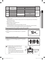
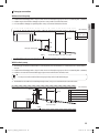
Drainpipe connection
Without the drain pump
Unit : inch(mm)
A
Hanger
A
39.37~59.05
(1,000~1,500)
B
1.96 (50)
ENGLISH
1. Install horizontal drainpipe with a slope of 1/100 or more and fix it by hanger space of 39.37~59.05inch(1,000~1,500mm).
2. Install U-trap at the end of the drainpipe to prevent a nasty smell to reach the indoor unit.
3. Do not install the drainpipe to upward position. It may cause water flow back to the unit.
H≥B
1/2H
Drain pipe cleaning hole
Ceiling
Horizontal drainpipe more than 1/100 slope
With the drain pump
1. The drain pipe should be installed within 12.99inch(330mm) from the flexible hose and then lift down 0.79inch(20mm)
or more.
2. Install horizontal drainpipe with a slope of 1/100 or more and fix it by hanger space of 39.37~59.05inch(1,000~1,500mm).
3. Install the air vent in the horizontal drainpipe to prevent water flow back to the indoor unit.
NOTE
• You may not need to install it if there were proper slope in the horizontal drain pipe.
4. The flexible hose should not be installed upward position, it may cause water flow back to the indoor unit.
Unit : inch(mm)
A
Air vent
B
D
Hanger
B 7.87(200) or more
C 0.79(20) or more
C
Flexible hose
A 39.37~59.0 (1,000~1,500)
D 11.81(300) or more less
E Within 12.99(330)
E
Horizontal drainpipe more
than 1/100 slope
Ceiling
25
Big Duct_IBIM_E_33766-3.indd 25
2012-01-13 오후 9:40:31
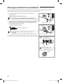
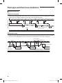
Drain pipe and drain hose installation
Centralized drainage
Without the drain pump
3.94inch(100mm) or more
1. Install horizontal drainpipe with a slope of 1/100 or more and fix it by hanger space of 39.37~59.05inch(1,000~1,500mm).
2. Install U-trap at the end of the drainpipe to prevent a nasty smell to reach the indoor unit.
Ceiling
Horizontal drainpipe more
than 1/100 slope
With the drain pump
1. Install main air vent at the front of the farthest indoor unit from the main drain when installed indoor units are more than 3.
2. You may need to install individual air vent to prevent water flow back at the top of each indoor unit drainpipe.
39.37~59.05inch
(1,000~1,500mm)
Hanger
Main air vent
Individual
air vent
12.99inch (330mm)
or less
Main drainpipe
Centralized horizontal drainpipe
(more than 1/100 slope)
26
Big Duct_IBIM_E_33766-3.indd 26
2012-01-13 오후 9:40:32
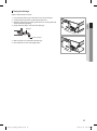
Testing the drainage
Prepare a little water about 2 liters.
ENGLISH
1. Pour water into the base pan in the indoor unit as shown in figure.
2. Confirm that the water flows out through the drain hose.
3. When the drain pump is installed, operate the unit as cooling mode and
check a drain pump pumping.
4. Check drain water drops at the end of the drain pipe.
Drainpipe
Drain pan
Drain water drops
5. Make sure there is no water leak at the drainage.
6. Reassemble the cover of water supply intake.
27
Big Duct_IBIM_E_33766-3.indd 27
2012-01-13 오후 9:40:32
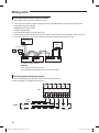
Wiring work
Power and communication cable connection
1. Before wiring work, you must turn off all power source.
2. Indoor unit power should be supplied through the breaker ( ELCB or MCCB+ELB ) separated by the outdoor power.
ELCB: Earth Leakage Circuit Breaker
MCCB:Molded Case Circuit Breaker
ELB:Earth Leakage Breaker
3. The power cable should be used only copper wires.
4. Connect the power cable{1(L), 2(N)} among the units within maximum length and communication cable(F1, F2) each.
5. Connect V1, V2(for DC12V) and F3, F4(for communication) when installing the wired remote control.
Outdoor Unit
Wired Remote
Control
220-240V~
MCCB+
ELB
or
ELCB
Indoor Unit 1
Indoor Unit 2
Indoor Unit 3
❋❋ ELCB : Essential Installation
WARNING :
Power off before connecting any wires;
Indoor PBA will be damaged while V1,V2,F3,F4 short each other.
Connecting power for optional product
ffWhen installing optional product, make sure to follow below current capacity.
❋❋ Optional product is not supplied by manufacturer.
T/B
1(L)
2(N)
Vc
Vc
Vw
Vw
HOT
COIL
POWER : L
POWER : N
OPTION
VENTILATOR
AC, Below 2A
AC, Below 2A
28
Big Duct_IBIM_E_33766-3.indd 28
2012-01-13 오후 9:40:32
Selecting compressed ring terminal
Silver solder
0.16 (4)
Standard
dimension
E
F
L
d2
Allowance
Min.
Min.
Max.
Standard
dimension
t
Allowance
Min.
0.26 (6.6) ±0.0079
(±0.2)
0.31 (8)
0.13
(3.4)
+0.012 (+0.3)
±0.0079
0.067(1.7)
(±0.2)
-0.0079 (-0.2)
0.16
(4.1)
0.24
(6)
0.63
(16)
0.17 (4.3)
+0.0079 (+0.2) 0.028
(0.7)
0
0.26 (6.6) ±0.0079
(±0.2)
0.17
(4.2)
+0.012 (+0.3)
±0.0079
0.091(2.3)
(±0.2)
-0.0079 (-0.2)
0.24
(6)
0.24
(6)
0.69
(17.5)
0.17 (4.3)
+0.0079 (+0.2) 0.031
(0.8)
0
±0.0079
(±0.2)
0.22
(5.6)
+0.012 (+0.3)
±0.0079
0.134(3.4)
(±0.2)
-0.0079 (-0.2)
0.24
(6)
0.20
(5)
0.79
(20)
0.17 (4.3)
+0.0079 (+0.2) 0.035
(0.9)
0
0.0023
(1.5)
0.16 (4)
0.0039
(2.5)
0.16 (4)
0.33 (8.5)
0.0062 (4)
0.16 (4)
0.37 (9.5)
0.16 (4)
d1
ENGLISH
Unit : inch(mm)
Nominal
Nominal
B
D
dimensions dimensions
Standard
Standard
for cable
for screw
Allowance
Allowance
dimension
[inch2(mm2)] [inch2(mm2)] dimension
Specification of electronic wire
Power supply
MCCB
ELB
Power cable
Earth cable
Communication cable
XA
XA, 30 mA
0.1 sec
0.0039inch2
(2.5mm2)
0.0039inch2
(2.5mm2)
0.0012~0.0023inch2
(0.75~1.5mm2)
Max : 242V
Min : 198V
❋❋ Run transmission wiring between the indoor and outdoor units through a conduit to protect against external forces, and
feed the conduit through the wall together with refrigerant piping.
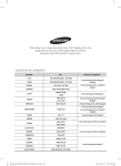
❋❋ Rating current
Unit
ND✴✴✴HH✴✴✴
Model
Rating current
✴✴220✴✴
3.8A
✴✴280✴✴
5.9A
ffDecide the capacity of ELCB(or MCCB+ELB) by below formula.
The capacity of ELCB(or MCCB+ELB) X[A] = 1.25 X 1.1 X ∑Ai
❋❋ X : The capacity of ELCB(or MCCB+ELB).
❋❋ ∑Ai : Sum of Rating currents of each indoor unit.
❋❋ Refer to each installation manual about the rating current of indoor unit.
ffDecide the power cable specification and maximum length within 10% power drop among indoor units.
n
∑(
k=1
Coef×35.6×Lk×ik
1000×Ak
) < 10% of input voltage[V]
• coef : 1.55
• Lk : Distance among each indoor unit[ft(m)], Ak : Power cable specification[inch2(mm2)]
ik : Running current of each unit[A]
29
Big Duct_IBIM_E_33766-3.indd 29
2012-01-13 오후 9:40:32
Wiring work
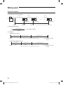
Example of Installation
ffTotal power cable length L = 328ft(100m), Running current of each units 1[A]
ffTotal 10 indoor units were installed
10[A]
9[A]
1[A]
ELCB
Or MCCB+
ELB
Indoor unit 1
0ft(0m)
32.8ft(10m)
Indoor unit 10
Indoor unit 2
65.6ft(20m)
328ft(100m)
ffApply following equation
n
∑(
Coef×35.6×Lk×ik
) < 10% of input voltage[V]
1000×Ak
k=1
❋❋ Calculation
• Installing with 1 sort wire.
0.0039inch2(2.5mm2)
0.0039inch2(2.5mm2)
-2.2[V]
-2.0[V]
220[V]
············ 0.0039inch2(2.5mm2) ············
-(2.2+2.0+1.8+1.5+1.3+1.1+0.9+0.7+0.4+0.2)=-11.2[V]
208.8[V](Within 198V~242V)
it's okay
• Installing with 2 different sort wire.
0.0062inch2(4.0mm2)
220[V]
-1.4[V]
0.0062inch2(4.0mm2)
············ 0.0039inch2(2.5mm2) ············
-1.2[V]
-(1.4+1.2+1.8+1.5+1.3+1.1+0.9+0.7+0.4+0.2)=-10.5[V]
209.5[V](Within 198V~242V)
it's okay
30
Big Duct_IBIM_E_33766-3.indd 30
2012-01-13 오후 9:40:33
CAUTION
ENGLISH
• Select the power cable in accordance with relevant local and national regulations.
• Wire size must comply with local and national code.
• For the power cable, use the grade of H07RN-F or H05RN-F materials.
• You should connect the power cable into the power cable terminal and fasten it with a clamp.
• The unbalanced power must be maintained within 10% of supply rating among whole indoor units.
• If the power is unbalanced greatly, it may shorten the life of the condenser. If the unbalanced power is exceeded
over 10% of supply rating, the indoor unit is protected, stopped and the error mode indicates.
• To protect the product from water and possible shock, you should keep the power cable and the connection
cord of the indoor and outdoor units in the iron pipe.
• Connect the power cable to the auxiliary circuit breaker.An all pole disconnection from the power supply must
be incorporated in the fixed wiring[≥(1/8"(3mm)].
• You must keep the cable in a protection tube.
• Keep distances of 2"(50mm) or more between power cable and communication cable.
• Maximum length of power cables are decided within 10% of power drop. If it exceeds, you must consider
another power supplying method.
• The circuit breaker(ELCB or MCCB+ELB) should be considered more capacity if many indoor units are connected
from one breaker.
• Use round pressure terminal for connections to the power terminal block.
• For wiring, use the designated power cable and connect it firmly, then secure to prevent outside pressure being
exerted on the terminal board.
• Use an appropriate screwdriver for tightening the terminal screws. A screwdriver with a small head will strip the
head and make proper tightening impossible.
• Over-tightening the terminal screws may break them.
• See the table below for tightening torque for the terminal screws.
Tightening torque [ft•lb(kgf•cm)]
M4
0.87~1.07 (12.0~14.7)
31
Big Duct_IBIM_E_33766-3.indd 31
2012-01-13 오후 9:40:33
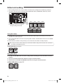
Indoor unit setting
1. Before installing the indoor unit, assign an address to the indoor unit according to the air conditioning system plan.
2. The address of the indoor unit is assigned by adjusting MAIN(SW01, SW02) and RMC(SW03, SW04) rotary switches.
SW01
SW02
SW03
SW04
❋❋ The designs and shape are subject to
change according to the model.
SW05
SW06
SW07
Setting Main Address
ffThe MAIN address is for communication between the indoor unit and the outdoor unit. Therefore, you must set it to
operate the air conditioner properly.
ffYou can set the MAIN address from ‘00’ to ‘99’ by mixing SW01 and SW02. The MAIN address from ‘00’ to ‘99’ should differ
from each other.
ffCheck the indoor unit address on the plan that you are to install and set the address according to the plan.
NOTE
• You may not need to set main address if you selected Auto Address Setting from the outdoor unit: see details on
the outdoor unit installation manual.
ex) When MAIN address is set as “12”.
Setting RMC Address
ffThe SW03 and SW04 RMC switch is the address setting switch for controlling the indoor unit with the centralized
controller.
ffYou must set the SW03, SW04 and K2 switch when using the centralized controller.
ffYou don’t have to set the SW03 and SW04 RMC switch when not using the centralized controller.
ex) When MAIN address is set as “12”.
SW03
SW04
32
Big Duct_IBIM_E_33766-3.indd 32
2012-01-13 오후 9:40:33
Additional functions
No.
ON
OFF
K1
External room sensor
Not use
Use
K2
Centralized controller
Not use
Use
K3
-
-
-
K4
Drain Pump
Not use
Use
ENGLISH
SW05
Function
K1 K2 K3 K4
❋❋ K1 OFF
Heating mode : Setting temperature compensation value = 0°F(0°C)
Thermo OFF Fan OFF

No.
SW06
Function
ON
OFF
K5
Heating Current Temperature
Compensation
+3.6°F(+2°C)
+9°F(+5°C)
K6
Filter Time
1,000 hours
2,000 hours
K7
Hot Water Heater
Not Use
Use
K8
-
-
-
Function
ON
OFF
K9
Indoor Expansion Valve For Heating Stop
Fix 160 step
0 or 160 step
K5 K6 K7 K8

No.
SW07
K10
Wired Remocon Group Master
Not Use
Use
K11
External control
Not Use
Use
K12
Operation output
Thermal ON
Operation ON
K9 K10 K11 K12
33
Big Duct_IBIM_E_33766-3.indd 33
2012-01-13 오후 9:40:34
Final checks and user tips
To complete the installation, perform the following checks and tests to ensure that the air conditioner operates correctly.
1. Check the followings.
ffStrength of the installation site
ffTightness of pipe connection to detect a gas leak
ffElectric wiring connections
ffHeat-resistant insulation of the pipe
ffDrainage
ffEarth conductor connection
ffCorrect operation (follow the steps below)
After finishing the installation of the air conditioner, you should explain the following to the user. Refer to appropriate pages
in the User’s Manual.
1. How to start and stop the air conditioner
2. How to select the modes and functions
3. How to adjust the temperature and fan speed
4. How to adjust the airflow direction
5. How to set the timers
6. How to clean and replace the filters
NOTE
• When you complete the installation successfully, hand over the User & Installation Manual to the user for storage
in a handy and safe place.
34
Big Duct_IBIM_E_33766-3.indd 34
2012-01-13 오후 9:40:34
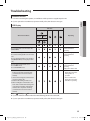
Troubleshooting
Detection of errors
ffIf an error occurs during the operation, an LED flickers and the operation is stopped except the LED.
ffIf you re-operate the air conditioner, it operates normally at first, then detect an error again.
ENGLISH
LED Display
Indicators
Concealed Type
Abnormal conditions
Green
Red
Operating
Standard Type
Power reset
Error of temperature sensor in indoor unit
(OPEN/SHORT)
Displayed on appropriate
indoor unit which is
operating
Error of heat exchanger sensor in indoor unit
Error of heat exchanger OUT sensor in indoor
unit
Error of outlet temperature sensor in indoor
unit (OPEN/SHORT): For heat pump models
only
Displayed on appropriate
indoor unit which is
operating
Error of outdoor temperature sensor
Error of COND sensor
Error of DISCHARGE sensor
Displayed on appropriate
indoor unit which is
operating
Displayed on outdoor unit
1. No communication for 2 minutes
between indoor unit and outdoor unit
(communication error for more than 2
minutes)
2. Indoor unit receiving the communication
error from outdoor unit
3. Outdoor unit tracking 3 minute error
4. When sending the communication error
from outdoor unit the mismatching of the
communication numbers and installed
numbers after completion of tracking.
(communication error for more than 2
minutes)
1. Error of indoor unit :
Displayed on the indoor
unit regardless of
operation
2. Error of outdoor unit :
Displayed on the indoor
unit which is operating
● On 
Flickering 
Off
ffIf you turn off the air conditioner when the LED is flickering, the LED is also turned off.
ffIf you re-operate the air conditioner, it operates normally at first, then detect an error again.
35
Big Duct_IBIM_E_33766-3.indd 35
2012-01-13 오후 9:40:34
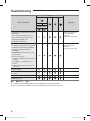
Troubleshooting
Indicators
Concealed Type
Abnormal conditions
Green
Red
Operating
Standard Type
Self-diagnostic error (including the indoor unit
not detected)
1. Error of electronic expansion valve close
2. Error of electronic expansion valve open
3. Breakaway of EVA OUT sensor
4. Breakaway of EVA IN sensor
Displayed on appropriate
indoor unit which is
operating
Displayed on outdoor unit
5. Breakaway of COND MID sensor
6. 2nd detection of refrigerant completely leak
7. 2nd detection of high temperature COND
8. 2nd detection of high temperature
DISCHARGE
9. COMP DOWN due to 2nd detection of low
pressure switch
10. Error of reverse phase
11. Compressor down due to 6th detection of
freezing
12. Self-diagnosis of condensation sensor
(G8, G9)
13. Compressor down due to condensation
ratio control
Displayed on appropriate
indoor unit which is
operating
Displayed on outdoor unit
Error of float switch
Error of setting option switches for optional
accessories
EEPROM error
EEPROM option error
● On 
Flickering 
Off
ffIf you turn off the air conditioner when the LED is flickering, the LED is also turned off.
ffIf you re-operate the air conditioner, it operates normally at first, then detect an error again.
36
Big Duct_IBIM_E_33766-3.indd 36
2012-01-13 오후 9:40:35
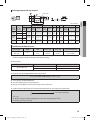
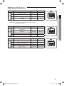
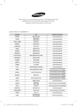
Option table
E.S.P(External Static Pressure)setting for phase control motor
Static Pressure(mmAq)
Model
Step
5
10
15
20
25
28
ENGLISH
With its phase control motor, you can adjust the indoor unit fan speed depending on the installation condition. If the external
static pressure is high so that the duct becomes longer or if the external static pressure is low so that the duct becomes
shorter, adjust the fan speed by referring the following table.
Option code for indoor unit
HI
ND220HHXCE
MID
LOW
HI
ND280HHXCE
MID
LOW
015A17160097 015A171600C7 015A171600E8 015A1716024D 015A1716029F
-200001300000 -200001300000 -200001300000 -200001300000 -200001300000
-
015A17170207 015A17170229 015A1717025B 015A1717029E 015A171703D1 015A171703F3
-200001300000 -200001300000 -200001300000 -200001300000 -200001300000 -200001300000
•
NOTE
represents E.S.P(External Static Pressure)range of factory setting. You don’t have to adjust the fan speed
. When it is out of
, input
separately if the external static pressure of the installation place is in
the appropriate option code.
• If you input the inappropriate option code, error may occur or the air conditioner is out of order. The option code
must be inputted correctly by the installation specialist or service agent.
37
Big Duct_IBIM_E_33766-3.indd 37
2012-01-13 오후 9:40:35