1
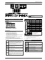
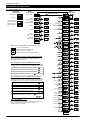
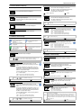
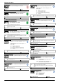
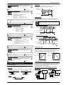
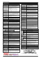
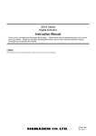
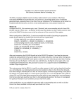
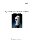
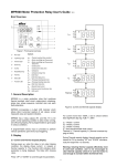
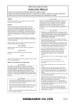
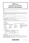
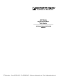
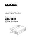
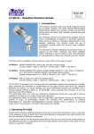
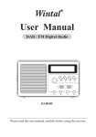
MSD16A-E01-A May. 2006 Safety Cautions Digital Indicator WARNING SD16A Series • Instruction Manual • • The SD16A Series indicator is designed to indicate temperature, humidity and other physical data for general industrial equipment. Do not apply this instrument to other objects in a way that may cause grave effects on human safety. In using this product, be certain to house it, for example, in a control panel, so that the terminals cannot come into contact with personnel. Do not take this instrument out of its case or put your hand or any conductor inside the case. Such conduct may lead to an accident that endangers life or causes serious injury due to electric shock. CAUTION • Please ensure that this instruction manual is given to the final user of the instrument. • Preface • Thank you for purchasing Shimaden products. Please check that the delivered product is the correct item that you ordered. This instruction manual is meant for those who will be involved in the wiring, installation, operation and routine maintenance of the SD16A series, and describes about cautions, mounting, wiring, functions, and operation. • Please observe the contents, and always keep the manual close at hand when handling this instrument. The following headings give a description of matters requiring user attention concerning safety, damage to machines and equipment, additional explanations and commentaries are described under the following headings. Note WARNING Items concerning matters that may lead to an accident producing human injury or death, if the warning is not observed. CAUTION Items concerning matters that may lead to an accident producing damage to machines or equipment, if the caution is neglected. Note • • Additional explanations and commentaries. • Contents Preface..................................................................................................... 1 • Contents................................................................................................... 1 Safety Cautions........................................................................................ 1 1. Introduction .......................................................................................... 2 1-1. Check before use......................................................................... 2 1-2. Notes for use ............................................................................... 2 • • 2. Installation and wiring ........................................................................... 2 2-1. Installation site (environmental conditions)................................... 2 2-2. Mounting...................................................................................... 2 To avoid damage to the connected equipment, facilities or the product itself due to a fault of the product, safety countermeasure must be taken before usage, such as proper installation of the fuse and the overheating protection device. An alert symbol is printed on the terminal nameplate attached to the case. It warns not to touch the electrical charging parts when the power is being supplied, so as to avoid the risk of electrical shock. Install a switch or breaker on the external source power circuit connecting to the source power terminal as a means to shut down the power. The switch or breaker should be installed adjacent to the instrument in a position that allows the operator easy access. Regarding the fuse: Since this instrument has no built-in fuse, make sure to install a fuse in the electric circuit connecting to the source power terminal. Install the fuse in a position between the switch or breaker, and the instrument and attach it to the L side of the source power terminal. Fuse Rating: 250V AC 1.0A/Time-lag (T) or Medium Time-lag (M) The load of voltage and current to be applied to the output terminal (analog output) and the alarm terminal must be within the rated range. If the range is exceeded, the instrument will overheat causing the risk of the instrument being damaged and its life reduced. As for the rating, please refer to "8. Specification." The unit connected to the output terminal should conform to the requirements of IEC61010-1. Do not apply over-rated voltage or current to the input terminal. That will cause the risk of the instrument being damaged and its life reduced. As for the rating, please refer to "8. Specification." In case the input type is voltage (mV or V) or current (4 ~ 20mA), the unit connected to the output terminal should conform to the requirements of IEC61010-1. Take care to prevent metal or other foreign matter from obstructing the ventilating hole for heat radiation. It will cause damage to the instrument and may even result in fire. Do not block the ventilating hole. Also avoid dust accumulation. Any rise in temperature or insulation failure may result in a risk of the instrument being damaged and its life reduced. As for the clearance space for installing the instrument, refer to "2-3 External dimensions and panel cutout." Repeating withstanding tests on voltage, noise, surging may lead to the deterioration of the instrument, so please be careful. Strictly refrain from remodeling and using the instrument improperly. Copyright © SHIMADEN CO., LTD. All rights reserved. 2-3. External dimensions and panel cutout ......................................... 2 2-4. Wiring .......................................................................................... 2 2-5. Terminal arrangement .................................................................. 3 3. Names and functions for front panel..................................................... 3 3-1. Names ......................................................................................... 3 3-2. Functions ..................................................................................... 3 4. Measuring range code table ................................................................. 3 5. Error messages.................................................................................... 3 6. Instruction for each screen ................................................................... 4 6-1. Screen sequences ....................................................................... 4 6-2. Power ON Screen Group ............................................................. 5 6-3. Mode 0 Screen Group.................................................................. 5 6-4. Mode 1 Screen Group.................................................................. 5 7. Optional features overview ................................................................... 7 7-1. Alarm output ................................................................................ 7 7-2. Analog output............................................................................... 7 7-3. Sensor power supply ................................................................... 7 8. Specification......................................................................................... 8 1 SD16A Instruction Manual 1. Introduction Note 1-1. Check before use 2-2. Mounting Although the instrument passes thorough quality checks before shipment, when the instrument is delivered, please confirm the type code number, check the external conditions and the list of accessories to make sure that there is no apparent damage or discrepancy. 1 Cut a fitting hole by referring to the panel cutout dimensions in section 2-3. The applicable thickness of the panel is 1.0 ~ 4.0mm. 2 Insert the indicator into the hole from the front of the panel, as it has catching claws to fix it in position. Confirmation of the type code Check the type code printed on the label on the packing case with the following table to confirm that the delivered goods meet your order. Item Code Note SD16A- 48 × 96 DIN size Digital Indicator Universal-input Refer to "4. Measuring range code table" for Thermocouple details. R.T.D. (Pt100, JPt100) In case voltage input, 8 Voltage (Input impedance scaling/reverse scaling is 500 kΩ min.) 2. Input (Note 1) available. 0~10mV DC (Note 2) 0~5, 1~5, 0~10V DC Current 4~20mA DC Scaling/reverse scaling 4 An external receiving resistor is available (Note 2) provided. 90- 100~240V AC ± 10% (50/60Hz) 3. Power supply 08- 24V AC (50/60Hz) /DC ±10% 0 None Separate setting/separate output 2-point (a-contact, 4. Alarm output (option) 1 "COM" used commonly) Contact rating 240V AC 1.5A/resistive load 0 None 3 0~10mV DC Output resistance 10Ω Scaling/reverse 5. Analog output 4~20mA DC Load resistance 300Ω scaling available 4 or sensor power supply (Within max. (option) (Note 3) measuring 6 0~10V DC Load current 1mA max. range) 8 Sensor power supply 24V±3V DC 25mA max. 0 None 6. Communication function 5 RS-485 (option) 7 RS-232C 0 Without 7. Remarks 9 With Note 2 Note 3 External dimensions Unit: mm Panel cutout Unit: mm 2-4. Wiring The instrument supports full universal input; however please select one of two codes, as an external receiving resistor (250Ω) is supplied for current input. If no external receiving resistor is required, a code 8 specification product can be used for current input. Scaling range: -1999 ~ 9999 Unit Span: 10 ~ 10000 Unit When the 08 power supply code (24V AC/DC) is selected, the sensor power supply cannot be selected. WARNING • • • Accessory list check • • • Unit label seal 1 sheet Instruction Manual 1 copy Communication Interface Manual (in case the optional communication option is selected) 1 copy Note • • • Contact our local agent or [email protected] via e-mail for any problems about the product, accessories or related items. • • 1-2. Notes for use • • As the SD16A is a panel installation type indicator, use it by mounting on a panel. 2-3. External dimensions and panel cutout Specifications 1. Series Note 1 The environmental conditions fall under installation category II of IEC 60664, and the pollution degree is "2". • Avoid operating the front panel keys with hard or sharp objects. Lightly touch the operating keys with your fingertips for operation. When cleaning, do not use a solvent such as a thinner. Wipe the instrument with a dry cloth lightly. • • 2. Installation and wiring • 2-1. Installation site (environmental conditions) • CAUTION • Do not install the instrument in such environmental conditions as those listed below. Otherwise, damage may be caused to the instrument, even resulting in fire. • Flammable or corrosive gas, oil soot or dust that deteriorates the insulation is generated or abundant. • Ambient temperature is below −10°C or above 50°C. • Ambient humidity is higher than 90% RH, or below dew point. • Strong vibrations or impacts are generated or transferred. • High-voltage power lines exist in the neighborhood, or induction interference. • Exposure to direct sunlight or dew drops. • The elevation is above 2000m. • When wiring the unit, be sure to cut the power supply OFF, or there will be a risk of electric shock. ) is grounded. Make sure the protective conductor terminal ( Otherwise, a serious electric shock may result. After completing the wiring, do not touch the terminals and electrically charged parts while the power is ON. Make wiring according to the layout in "2-5. Terminal arrangement." Use ring tongue terminals of 7mm or narrower width to meet M3.5 screws. In case of thermocouple input, use a compensation wire with the type of thermocouple selected. The external resistance should be100Ω or less. In case of R.T.D. input, the resistance value per lead wire should be 5Ω or less, and all three wires should have the same resistance value. Avoid arranging the input signal line to pass through the same conduit or duct with high-voltage power lines. The shield wire (one-point grounding) is effective to eliminate electrostatic induction noises. An effective way to eliminate the magnetic induction noises is to twist the input wire in short and equal intervals. For the source power connection, use a wire or cable having a cross-section of 1mm2 or larger, and a performance capacity equivalent to 600V vinyl insulation wire. The grounding wire should have a cross-section of 2mm2 or larger, and the grounding work should ensure a ground resistance of 100Ω or less. The symbol expresses the functional earth terminal. Please connect it to the ground as much as possible to avoid the adverse impact from noise. Screw the terminal connection securely. Tightening torque 1.1 · Nm (11kgf · cm) Noise filter In case the instruments are affected by the power supply noise, install a noise filter to avoid operational errors. Mount the noise filter on the grounded panel and connect the noise filter output and the power supply terminal of the indicator with the Make wire with the miniminimum possible distance. mum possible distance 100~200V AC 50/60 Hz 100~200V AC SD16A Noise filter Recommended noise filter: ZMB2203-13 from TDK 2 Grounding SD16A Instruction Manual 2-5. Terminal arrangement Com RS-232C RS-485 SG SG COM AL1 AL2 SD RD 11 12 13 15 16 17 18 19 18 19 11 12 13 14 15 16 17 18 19 20 1 2 3 4 5 6 7 8 9 Power supply 1 L 2 3 1 N 2 L 100~ 240V AC 50/60Hz 10 Inputs 3 N 24V AC/DC TC 6 RTD 7 6 A Voltage (V) 7 B 9 5 6 Voltage (mV) 7 6 7 Current (mA) 5 6 7 B 3. Names and functions for front panel 4. Measuring range code table 3-1. Names Input type Front panel Code B R S [3] Key switches 3-2. Functions Thermocouple Voltage [1] Monitoring LEDs • AL1 (Alarm 1) output monitoring LED (red) The LED lights when the assigned alarm is ON. • AL2 (Alarm 2) output monitoring LED (red) The LED lights when the assigned alarm is ON. • SET (parameter setting) monitoring LED (green) The LED lights when the screen displayed is not the basic screen (0-0). • COM (communication) monitoring LED (green) The LED lights when the communication mode is on remote control. R.T.D Universal Input (Note 1) [1] Monitoring LEDs [2] LED display for measured value Do not connect other than the specified input type to terminal. Note Current Note 1 Note 2 Note 3 [2] LED display for measured value (red) • The current PV value is displayed on the basic screen (0-0). • The type of parameters is displayed on each parameter display screen. • The set value is displayed on each parameter setting screen. Note 4 [3] Key switches Measuring range Measuring range (°C) (°F) 01 02 03 0 ~ 1800 0 ~ 1700 0 ~ 1700 0 ~ 3300 0 ~ 3100 0 ~ 3100 -199.9 ~ 800.0 0 ~ 1200 0 ~ 700 0 ~ 600 -199.9 ~ 300.0 0 ~ 1300 -199.9 ~ 300.0 0 ~ 600 0 ~ 2300 -199.9 ~ 600.0 -100.0 ~ 100.0 -199.9 ~ 500.0 -100.0 ~ 100.0 -300 ~ 1500 0 ~ 2200 0 ~ 1300 0 ~ 1100 -300 ~ 600 0 ~ 2300 -300 ~ 600 0 ~ 1100 0 ~ 4200 -300 ~ 1100 -150.0 ~ 200.0 -300 ~ 1000 -150.0 ~ 200.0 0 ~ 10mV 0 ~ 5V 1 ~ 5V 0 ~ 10V 04 05 06 07 08 09 10 11 12 31 32 33 34 71 81 82 83 4 ~ 20mA 95 K E J T N U L WRe5-26 Pt JPt Note Note 2 Note 3 Note 3 Note 4 Note 4 0.0 ~ 100.0 Scaling available Scaling range : -1999 ~ 9999 Unit Span : 10 ~ 10000 Unit In case universal input type is selected, K (Code 05, 0 ~ 1200°C) is set at factory default. The accuracy of 400°C or below of thermocouple B is ±5%FS. The accuracy of thermocouple T or U is ±0.5%FS at above -100°C and 0°C or below, and ±1%FS at -100°C or below. In case of Pt (Code 31) or JPt (Code 33), scale over occurs at -240.0°C (-400°F). 5. Error messages Parameter key • On a display screen, shifts the screen to the next. • Switches from Mode 0 screen group/Mode 1 screen group to Mode 1 screen group/Mode 0 screen group. By pressing this key for two seconds or longer on screen 0-0 or screen 1-0, shifts to the screen 1-0 or to the screen 0-0 respectively. One of the following error messages is displayed on the basic screen (0-0): When the thermocouple or A of R.T.D. is burnt out. Also indicated when the PV value exceeds the higher-limit of the measuring range by about 10% When the B of R.T.D. (terminal No.7) is burnt out. When the PV value is below the lower-limit of the measuring range by about 10%, for such a reason as the reverse polarity of the input wiring type. Down key • On a setting screen, decrements the value. The last digit decimal point blinks until the value is registered by pressing the Entry key. When the cold junction (CJ) is abnormal on the higher side in the thermocouple input. Up key • On a setting screen, increments the value. The last digit decimal point blinks until the value is registered by pressing the Entry key. When the cold junction (CJ) is abnormal on the lower side in the thermocouple input. When the B of the R.T.D. (terminal No.9) is burnt out, or two or more wires of A, B, B are broken. Entry key • On a setting screen, registers the value that is modified by the Up/Down key. The last digit of the decimal point blinks until this registration by pressing the Entry key. • Shifts between a display screen and the setting screen. In this case, the light of the last digit of decimal point goes out. 3 SD16A Instruction Manual 6. Instruction for each screen 6-1. Screen sequences Power ON Screen Group Mode 0 Screen Group Basic screen Model name Input type Alarm 1 latching release Measuring range lower-limit value Alarm 2 latching release Measuring range higher-limit value 0-0 For approx. two secs 1-0 Mode 1 Screen Group 1-1 0-1 Key lock 1-2 0-2 Display update cycle 1-3 0-3 PV bias Measuring range 1-4 0-4 PV filter Decimal places 0-5 1-5 Alarm 1 setting value Input unit 1-6 0-6 Alarm 2 setting value decimal places 0-0 1-7 to Basic screen 1-8 Each screen is classified by the screen frame as follows. Screens always displayed. Alarm 1 code Screens displayed or not displayed depending on some conditions. Screens displayed when any option is added. Alarm 1 hysterisis Key operations on screens of Power ON Screen Group Alarm 1 inhibit No key operation is required as screens alter automatically within Power ON Screen Group. 1-10 1-11 1-12 Alarm 2 code Key operations on screens of Mode 0 Screen Group Mode 0 Screen Group consists of screens that are often used under control operation. The commonly-used key operations are as follows: Alarm 2 hysterisis Shifting a display screen to the next display screen 1-13 1-14 Alarm 2 inhibit Shifting a display screen to the setting screen Returning from a setting screen to the display screen Shifting from 0-0 screen to 1-0 screen 1-9 1-15 approx. 2 secs. lower-limit value 1-16 Key operations on screens of Mode 1 Screen Group Mode 1 Screen Group consists of screens that are used less often than Mode 0 screens, and are required according to the input type or controllability. The commonly-used key operations are as follows: higher-limit value Communication mode Shifting a display screen to the next display screen Communication protocol Shifting a display screen to the setting screen Communication address Returning from a setting screen to the display screen Returning from any display screen of Mode 1 to 1-0 screen Returning from 1-0 screen to 0-0 screen approx. 2 secs. or Auto return feature If no key operation is executed on any screen but the Basic screen (0-0) for three minutes or more, the screen returns to the Basic screen automatically. Communication data format Communication start character Communication BCC operation Communication speed 1-17 1-18 1-19 1-20 1-21 1-22 1-23 1-24 Communication delay 1-0 to 1-0 screen 4 SD16A Instruction Manual 0-3 PV bias 6-2. Power ON Screen Group The following information is displayed automatically. The PV bias value is displayed or can be set. Model name The value is used for compensating input errors by the sensor, etc. When the value is set, the compensated PV is displayed. The model name (SD16A) is displayed. -1999 ~ 2000 Unit 0 Unit 0-4 PV filter Input type The PV filter time is displayed or can be set. The input type is displayed. The value is helpful for reducing the adverse effect of noise from a PV input. The type is either TC (thermocouple), Pt (R.T.D.), mV, V, or mA. The PV filtering is temporarily disabled when the instrument is recovering from scale over. Note Measuring range, lower-limit value 0 ~ 100 seconds The lower-limit value of the input is displayed. 100 0-5 Alarm1 setting value Alarm 1 setting value is displayed or can be set. Measuring range, higher-limit value One of the following Alarm 1 action types (1-9) is displayed on the screen. A1HA :Higher-limit absolute value A1LA :Lower-limit absolute value A1H.A. :Higher-limit absolute value (with latching) A1L.A. :Lower-limit absolute value (with latching) The higher-limit value of input is displayed. 6-3. Mode 0 Screen Group The following informational icons are used from this sub-section. Setting/display is available when the alarm option is supported. This screen is not displayed when non or So (scale over) is selected on Alarm 1 code screen (1-9). Note Measuring range lower-limit to higher-limit value Setting/display is available when the analog output option is supported. 0-6 Alarm 2 setting value Alarm 2 setting value is displayed or can be set. Setting/display is available when the communication option is supported. mV V mA Setting/display is available when the voltage or current input is specified. Setting/display is not available when the voltage or current input is specified. Setting range Initial value One of the following Alarm 2 action types (1-12) is displayed on the screen. A1HA :Higher-limit absolute value A1LA :Lower-limit absolute value A1H.A. :Higher-limit absolute value (with latching) A1L.A. :Lower-limit absolute value (with latching) Note This screen is not displayed when non or So (scale over) is selected on Alarm 2 code screen (1-12). Measuring range lower-limit to higher-limit value 0-0 Basic screen PV (measured value) is displayed. Note 1-0 Mode 1 initial screen In case the Alarm 1 or 2 signal is output with the latching feature, use key on this screen to release the Alarm 1 latching, or use key on this screen to release the Alarm 2 latching. This is the heading screen of Mode 1 screens. 1-1 Key lock This screen is displayed when Alarm 1 is in the latching state, and is used for releasing it from that state. Key lock status is displayed or can be set. When the key lock is set to ON, parameter value modification is not allowed. This screen is displayed in case Alarm 1 code (1-1) is selected from the one with latching, and when the instrument is in the latching state. Set the parameter RSET to stop the alarm output. OFF, ON The display update cycle of PV is displayed or can be set. KEEP : Alarm output is ON with latching feature. RSET : Releasing the alarm with latching feature. 0.25 ~ 5.00 secs. Set by 0.25 secs. The Alarm 1 output signal with latching feature can also be set to OFF by pressing key on the Basic screen (0-0). The input type is displayed or can be set. Refer to "4. Measuring range code table" for input type details. 01 ~ 12, 31 ~ 34, 71, 81 ~ 83, 95 This screen is displayed when Alarm 2 is in the latching state, and is used for releasing it from that state. 05 (K, TC 0 ~ 1200°C) 1-4 Decimal places This screen is displayed in case Alarm 2 code (1-12) is selected from the one with latching, and when the instrument is in the latching state. Set the parameter at RSET to stop the alarm output. The decimal place with/without status is displayed or can be set. dp_y : with decimal places dp_n : without decimal places As for the latching feature, refer to "Latching feature" of "7-1. Alarm output." KEEP : Alarm output is ON with latching feature. RSET : Releasing the alarm with latching feature. Note The Alarm 2 output signal with latching feature can also be set to OFF by key on the Basic screen (0-0). pressing KEEP, RSET 0.25 1-3 Measuring range KEEP 0-2 Alarm 2 latching release Note OFF 1-2 Display update cycle As for the latching feature, refer to "Latching feature" of "7-1. Alarm output." KEEP, RSET Lower-limit value 6-4. Mode 1 Screen Group 0-1 Alarm 1 latching release Note Higher-limit value In case the measuring range that doesn’t support decimal places is specified, this screen is not displayed. Once this setting is modified from "with decimal places" to "without decimal places", the values of input scaling, analog output scaling, alarm setting, alarm hysterisis, and PV bias are rounded to the nearest integer. Then that setting is modified to "with decimal places" again, the value after the decimal places remains 0. dp_y, dp_n KEEP 5 dp_y SD16A Instruction Manual 1-5 Input unit 1-12 Alarm 2 code The input unit is displayed or can be set. °C, °F The Alarm 2 action type is displayed or can be set. As for action types, refer to "Action type" of "7-1. Alarm output." °C non : none HA : Higher-limit absolute value LA : Lower-limit absolute value HA_L : Higher-limit absolute value (with latching) LA_L : Lower-limit absolute value (with latching) So : Scale over 1-6 Input scaling decimal places The scaling decimal places for voltage/current system input are displayed or can be set. mV V mA Note Note Other than voltage/current system input, display only. nnnn. ~ n.nnn Once the alarm code is changed, the preset values are initialized. However, they are not initialized when the code is changed HA<->HA_L, or LA<->LA_L. non, HA, LA, HA_L, LA_L, So LA n.n 1-13 Alarm 2 hysterisis 1-7 Input scaling lower-limit value The Alarm 2 hysterisis is displayed or can be set. The scaling lower-limit value for voltage/current input is displayed or can be set. Note mV V mA Note Other than voltage/current input, display only. The span between lower-limit and higher-limit is 10 ~ 10000. Reverse scaling is available. -1999 ~ 9999 Unit This screen is not displayed when non or So (scale over) is selected on the Alarm 2 code screen (1-12). 1 ~ 999 Unit 1-14 Alarm 2 inhibit 0 Unit The Alarm 2 inhibit status is displayed or can be set. 1-8 Input scaling higher-limit value The scaling higher-limit value for voltage/current input is displayed or can be set. Note mV V mA Note The analog output scaling lower-limit value is displayed or can be set. 1000 Unit Note The Alarm 1 action type is displayed or can be set. non : none HA : Higher-limit absolute value LA : Lower-limit absolute value HA_L : Higher-limit absolute value (with latching) LA_L : Lower-limit absolute value (with latching) So : Scale over The analog output scaling higher-limit value is displayed or can be set. Once the alarm code is changed, the preset values are initialized. However, they are not initialized when the code is changed HA<->HA_L, or LA<->LA_L. Note HA The communication mode is displayed or can be set. This screen is not displayed when non or So (scale over) is selected on the Alarm 1 code screen (1-9). LOC : Local mode. Data can be read out via communication. 20 Unit COM : Communication mode. Data can be set and read out via communication. The Alarm 1 inhibit status is displayed or can be set. Note This screen is not displayed when non or So (scale over) is selected on the Alarm 1 code screen (1-9). OFF, ON Higher-limit value 1-17 Communication mode 1-11 Alarm 1 inhibit Note Reverse scaling is available. The same value cannot be set for the lower-limit value (on screen 1-15) and the higher-limit value. Measuring range lower-limit value to higher-limit value The Alarm 1 hysterisis is displayed or can be set. 1 ~ 999 Unit Lower-limit value 1-16 Analog output scaling higher-limit value 1-10 Alarm 1 hysterisis Note Reverse scaling is available. The same value cannot be set for the lower-limit value and the higher-limit value (on screen 1-16). Measuring range lower-limit value to higher-limit value As for action types, refer to "Action type" of "7-1. Alarm output." non, HA, LA, HA_L, LA_L, So OFF 1-15 Analog output scaling lower-limit value 1-9 Alarm 1 code Note This screen is not displayed when non or So (scale over) is selected on the Alarm 2 code screen (1-12). OFF, ON Other than voltage/current input, display only. The span between the lower-limit and the higher-limit is 10 ~ 10000. Reverse scaling is available. -1999 ~ 9999 Unit 20 Unit Once the communication mode is modified to COM via communication, the setting can no longer be made with front panel keys. However, the modification from COM to LOC is available. For details, refer to the separated Communication Interface Instruction Manual. LOC, COM LOC OFF 1-18 Communication protocol The communication protocol is displayed or can be set. SHIM : Shimaden protocol ASC : MODBUS ASCII RTU : MODBUS RTU SHIM, ASC, RTU 6 SHIM SD16A Instruction Manual Inhibit action 1-19 Communication address When the alarm output inhibit action is set to ON (on screen 1-11 or 1-14), the inhibit action at power on is performed, as follows. The communication address is displayed or can be set. 1 ~ 100 PV (measured value) 1 Alarm setting value Hysterisis 1-20 Communication data format The communication data format is displayed or can be set. Alarm standby Left character Middle character Right character 7E1, 7E2, 7N1, 7N2, 8E1, 8E2, 8N1, 8N2 Latching feature The latching feature outputs the alarm signal constantly once PV is detected in the alarm action region, even if PV is out of the alarm action region later. The latching feature is disabled. The start character of communication data is displayed or can be set. Start character Text end End character Start character Text end End character ATT When PV is in the alarm action region, latching cannot be released. To release the latching, refer to the description of screen 0-0, 0-1, or 0-2. Note 7E1 1-21 Communication start character STX OFF Time Power ON : Data length (bits). 7 or 8 : Parity. E (even) or N (none) : Stop bit. 1 or 2 For MODBUS ASCII, specify one of the 7-bit format types. The default value is 7E1. For MODBUS RTU, specify one of the 8-bit format types. The default value is 8E1. Note ON Alarm signal The setting value is composed of three alphanumerical characters. Alarm action region Alarm setting value STX (02H) ETX (03H) CR (0DH) @ (40H) : (3AH) CR (0DH) Hysterisis PV (measured value) ON ON Alarm signal OFF MODBUS ASCII/RTU doesn’t use a start character. Note STX, ATT STX OFF Time The latching feature is enabled. Allowed Release of latching 1-22 Communication BCC operation The BCC operation method is displayed or can be set. Alarm setting value 1 : ADD operation from the start character to the text-end character 2 : 2’s complement after ADD operation from the start character to the text-end character. 3 : XOR operation from after the start character to the text-end character. 4 : BCC operation is not performed. Allowed Alarm action region Alarm region Hysterisis Operation of latching release PV (measured value) ON Alarm signal OFF MODBUS ASCII/RTU doesn’t use BCC. Note 1~4 1 7-2. Analog output 1-23 Communication speed Analog output is a feature that outputs PV value-based analog voltage or analog current. By setting the analog output scaling lower-limit value (screen 1-15) or higher-limit value (1-16), the analog output signal can be gained by PV value-base within a specified measuring range. The communication speed is displayed or can be set. Ao_L < Ao_H In case of 19200 bps, "1920" is displayed on the screen. Note 1200, 2400, 4800, 9600, 19200 bps Time Ao_L > Ao_H (reverse scaling) 100% 100% Analog output Analog output 9600 1-24 Communication delay The delay time by communication, between time of receiving a command and sending the reply, is displayed or can be set. 1 ~ 100 msec 0% The instrument supports two points of alarm optionally. Wiring example using with Humidity Sensor H71/TH71 Action type 24V DC 25mA The higher-limit absolute value alarm Hysterisis ON 18 19 For current (mA) Input POWER For voltage (V) Input The following alarm output action types (screen 1-9 or 1-12) are supported. H71/TH71 18 OUT OFF 100% 0% Alarm setting value OFF 11 12 13 14 100% 1 2 3 4 5 Scale over ON ON OFF 6 7 6 DC Alarm -10% 0% 5 OFF 100% 110% 7 1 8 7 9 10 17 18 19 20 SD16A 15 16 17 18 19 20 SD16A Alarm setting value 19 H71/TH71 IN/OUT 11 12 13 14 15 16 0% Ao_L Measuring range In case the optional DC sensor power supply (24V DC 25mA) is selected, the instrument can be used with the Humidity Sensor H71/TH71 series. Note that if 08 of power (24V AC/DC) from type code is selected, the sensor power supply cannot be specified. 7-1. Alarm output Hysterisis Ao_H 7-3. Sensor power supply 7. Optional features overview ON 0% Ao_H Measuring range 20 The lower-limit absolute value alarm Ao_L 2 3 4 5 5 6 7 6 DC 8 7 9 10 SD16A Instruction Manual 8. Specification Display Analog output (option) Digital display Measured value (PV), 7-segment, Red 4-digit LED Analog output type Action indication SET (green) : lit when parameter value is displayed COM (green) : lit when communication mode is set AL1/AL2 (red) : lit when alarm signal is output Output resolution Approx. 1/14000 Display accuracy ± (0.3%FS + 1 digit) within measuring range Excluding cold junction temperature compensation accuracy of thermocouple input. ± 5%FS for temperature below 400°C (752°F) of thermocouple B. Accuracy of thermocouple T or U is ±0.5%FS at above -100°C and 0°C or below, and ±1%FS at -100°C or below. Output accuracy ±0.3%FS of display value Scaling Within measuring range or within input scaling range (reverse scaling can be set). Output update cycle 0.25 secs Isolation Isolated between analog output and input, between analog output and alarm output, between analog output and communication, or between analog output and system. 0 ~ 10mV (Output resistance 10Ω) 0 ~ 10V (Load current 1mA max.) 4 ~ 20mA (Load resistance 300Ω max.) Display accuracy maintaining range 23°C±5°C (18 ~ 28°C) Display resolution Differs depending on the measuring range (0.001, 0.01, 0.1, 1) Measured value display range Sensor power supply (option) -10 ~ 110% of measuring range (Accuracy is only guaranteed when the value is within the measuring range). For R.T.D. input of -199.9 ~ 600.0°C: -240.0 ~ 680.0°C -199.9 ~ 500.0°C: -240.0 ~ 570.0°C For thermocouple K of -199.9 ~ 800.0°C: -273.1 ~ 900.0°C Output rating 24V ± 3V DC 25mA max. Depending upon instrument’s power ON-OFF status. Isolation Isolated between sensor power supply and input, between sensor power supply and alarm output, between sensor power supply and communication, or between sensor power supply and system. Restrictions Sensor power supply can't be selected when the analog output is selected. Sensor power supply can’t be selected when the power supply 24V is selected. Display update cycle 0.25 ~ 5.00 secs (0.25 secs step) When 0.50 secs or more is set, a difference may occur among the displayed value, the analog output, and the communication data. Setting Setting method Using four key switches on the front panel Setting protection feature by key lock ON/OFF is provided. Setting range Same as the measuring range. Communication (option) Input Input type Thermocouple, R.T.D., voltage (mV/V). Universal-input Thermocouple B, R, S, K, E, J, T, N {U, L (DIN43710)}, WRe5-26 For details, refer to the Measuring range code table. Communication type RS-232C, RS-485 Communication system Half duplex asynchronous communication method Communication speed 1200, 2400, 4800, 9600, 19200 bps Data format 7E1, 7E2, 7N1, 7N2, 8E1, 8E2, 8N1, 8N2 Communication address 1 ~ 100 100Ω max. Number of connectable devices 31 devices max. (for RS-485) Input impedance 500kΩ min. Delay 1 ~ 100 msec Burnout Standard feature (up-scale) Cold junction compensation accuracy ±1°C (within accuracy maintain range (18 ~ 28°C)) ±2°C (ambient temperature 5 ~ 18°C, 28 ~ 45°C) Communication protocol Shimaden standard protocol, MODBUS ASCII, MODBUS RTU (start character and BCC operation method can be selected for Shimaden standard protocol). R.T.D Isolation JIS Pt100 3-wire type, JPt100 3-wire type Amperage Approx. 0.25mA Isolated between communication and input, between communication and alarm output, between communication and analog output (sensor power supply), or between communication and system. Lead wire tolerable resistance 5Ω max./wire (each wire should have the same resistance) Miscellaneous mV 0 ~ 10mV DC Data storage V 0 ~ 5, 1 ~ 5, 0 ~ 10V DC Current 4 ~ 20mA DC External receiving resistor 250Ω (supplied if specified) Input scaling function Available in case of voltage (mV/V) or current (mA) input. Reverse scaling can be set. Scaling range -1999 ~ 9999 counts Span 10 ~ 10000 counts Decimal places None, 0.0, 0.00, 0.000 Sampling cycle 0.25 secs PV bias -1999 ~ 2000 PV filter 0 ~ 100 secs (PV filter is set to OFF when 0 sec) Isolation Isolated between input and analog output (sensor power supply), or between input and communication. Not isolated between input and system. Ambient conditions for use Input impedance 500kΩ min. Alarm output (option) Number of alarm points 2 points (AL1 and AL2), normally open, COM is commonly used. Alarm type One of the following six types can be assigned to each alarm. None, higher-limit absolute value alarm (with latching), higher-limit absolute value alarm (without latching), lower-limit absolute value alarm (with latching), lower-limit absolute value alarm (without latching), Scale over Setting range Within measuring range or within scaling range Alarm action ON-OFF action Hysteresis 1 ~ 999 Unit Inhibit action ON/OFF can be selected for each alarm output. Output type Contact 1a (COM is commonly used) Rating 240V AC 1.5A (resistive load) Output update cycle 0.25 secs Isolation Isolated between alarm output and input, between alarm output and analog output (sensor power supply), between alarm output and communication, or between alarm output and system. Not isolated between alarm output 1 and alarm output 2. By nonvolatile memory (EEPROM). Temperature -10 ~ 50°C Humidity 90%RH max. (no dew condensation) Height 2000m above sea level or lower Installation category II Degree of pollution 2 Power supply voltage (frequency) 100 ~ 240V AC ± 10% (50/60Hz) 24V AC (50/60Hz) /DC ±10% (option) Power consumption 11VA (100 ~ 240V AC) 8VA (24V AC) 5W (24V DC) Applicable standard Voltage Lead wire tolerable resistance Safety IEC61010-1, EN61010-1 EMC EN61326:1997+A1:1998, A2:2001, A3:2003 EMC testing display accuracy ±3%FS Dust proof /drip proof IP66 equivalent Isolation resistance Between all input/output terminals and power terminal: 500V DC 20MΩ min. Between all input/output terminals and ground terminal: 500V DC 20MΩ min. Dielectric strength Between all input/output terminals and power terminal: 2300V AC for one minute. Between power terminal and ground terminal: 1500V AC for one minute. Case material Black PPO resin molding (equivalent to UL94V-1) External dimensions H48 x W96 x D111 mm (inside of panel: 100mm) Mounting Push-in panel (one-touch mount) Panel thickness 1.0 ~ 4.0 mm Panel cutout H45 x W92 mm Weight Approx. 250g The contents of this manual are subject to change without notice. Distributed in New Zealand by: Any questions should be directed to your local agent, or send an e-mail to [email protected]. Christchurch Ph: +6433430646 Fx: +6433430649 Auckland 098271930 098271931 Printed in Japan www.intech.co.nz [email protected] 8