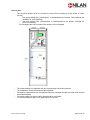
1
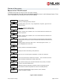
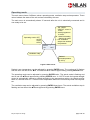
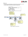
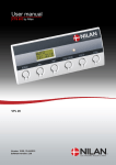
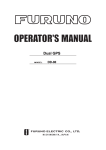
User manual CTS 602 by Nilan VP 18 EK Version: 10.00, 13-04-2015 Software-version: 2.30 Table of contents Table of contents ............................................................................................................................ 2 Figure table .................................................................................................................................... 2 Introduction..................................................................................................................................... 3 Types of units ................................................................................................................................. 4 Review of the thermometer sensors ............................................................................................... 5 CTS 602 panel ............................................................................................................................... 6 How to use the menu: ................................................................................................................. 6 Review of the menus ...................................................................................................................... 7 Menus in the CTS 602 control ..................................................................................................... 7 Operating mode .............................................................................................................................. 8 Main menu .................................................................................................................................. 9 Show alarms ............................................................................................................................. 10 Show data ................................................................................................................................. 13 User select 1 and 2 ................................................................................................................... 14 Setting of clock.......................................................................................................................... 15 Week programme ..................................................................................................................... 16 Factory settings for the 3 weekly programs: .............................................................................. 17 Central heating.......................................................................................................................... 18 Cooling ..................................................................................................................................... 23 Air exchange ............................................................................................................................. 24 Air filter ..................................................................................................................................... 25 Temp. control ............................................................................................................................ 26 Setting of language ................................................................................................................... 27 Faultfinding ................................................................................................................................... 28 Maintenance ................................................................................................................................. 29 Energy saving ............................................................................................................................... 32 Accessories .................................................................................................................................. 33 Figure table Figure 1: Types of units .................................................................................................................. 4 Figure 2: Diagram illustrating sensor location for VP 18 EK ............................................................ 5 Figure 3: CTS 602 panel................................................................................................................. 6 Figure 4: Menu headlines ............................................................................................................... 7 Figure 5: Main menu ....................................................................................................................... 8 Figure 6: Headlines in the ”Main menu” .......................................................................................... 9 Figure 7: The ”Show alarms” menu............................................................................................... 10 Figure 8: The ”Show data” menu .................................................................................................. 13 Figure 9: The ”User select” menu ................................................................................................. 14 Figure 10: Setting of clock ............................................................................................................ 15 Figure 11: The ”Week program” menu .......................................................................................... 16 Figure 12: The "Central heating" menu ......................................................................................... 18 Figure 13: The ”Hotwater” menu ................................................................................................... 22 Figure 14: The ”Cooling” menu ..................................................................................................... 23 Figure 15: The ”Air exchange” menu ............................................................................................ 24 Figure 16: The ”Air filter” menu ..................................................................................................... 25 Figure 17: The ”Temp. control” menu ............................................................................................ 26 Figure 18: The ”Language” menu ................................................................................................. 27 May be subject to change page 2 af 33 Introduction Please control that the following documents have been delivered together with the unit: - Directions for assembly and use - CTS 602 directions (this document) - Electrical chart The purpose of this manual is to clearly show the menus and possibilities of the CTS 602 control. The manual may contain functions and facilities which are not available on your system. Unless otherwise stated in the titles, the descriptions apply to all systems listed on page 4. It is possible to e.g. increase the speed of the exhaustion for a limited period of time. GETTING STARTED The system is delivered ready for use. The factory settings are suitable for most user requirements and it should therefore not be necessary to change any settings other than those found in the main menu. The main menu is described on pages 8 and 9. May be subject to change page 3 af 33 Types of units Compressor De-icing Water for domestic use x Option for cooling air x High pressure protection VP18 M2 EK Frost-protected heating coil 1 Heated air Nr. Type The control is made for the following ventilation units. x x x x Figure 1: Types of units May be subject to change page 4 af 33 Review of the thermometer sensors Figure 2: Diagram illustrating sensor location for VP 18 EK Explanation for figure 2: T1: T5 : T6 : T11: T12: T14: T15: is the thermometer sensor for the fresh air and should be placed at the north side of the building. shows the temperature of the condenser. shows the temperature of the evaporator is the temperature at the top of the hot water tank is the temperature at the bottom of the hot water tank is the temperature in the boiler is the thermometer sensor in the CTS 602 panel. The temperature of the sensors can be read in the “Show data” menu. May be subject to change page 5 af 33 CTS 602 panel Use of the CTS602 panel: - press ESC to go one step back in the menu - press qp to move up or down in a menu or to adjust an activated menu - press ENTERto activate a menu - press ENTERto confirm a menu - press OFF to turn off the unit - press ON to turn the unit on Figure 3: CTS 602 panel The following is indicated by the light-emitting diode at the front of the CTS 602 panel: Constant yellow light: the compressor is in operation Flashing yellow: the unit is in alarm condition The panel can show 2 lines of text with each 8 characters. The upper line shows a guiding text. The bottom line shows the matching values to the guiding text. The text in the display in “on” as long as there is power to the unit and will not turn off even though the unit is set to “off” or has not been operated for a longer period of time. How to use the menu: It is possible to adjust a value or a function by finding the matching menu via p or q. To activate the desired menu press ENTER. To adjust the settings of the value press ENTER until the value flashes. The adjustment can now be done viapq. To save the chosen value press ENTER. It is advisable to have the panel and/or the review of the menus near by during the reading of the menus. If none of the press buttons are activated for one minute the control will automatically return to the main menu. If you are in the middle of the programming when the control returns to the main menu all data will be saved if they previously are saved by pressing ENTER. It is always possible to return to the programming to continue. May be subject to change page 6 af 33 Review of the menus Menus in the CTS 602 control CTS 602 control has 12 menus (if the unit is with cooling). The control will have the main menu as starting point, (the menu in the full-drawn frame). From here it is possible to go through the other menus via pq. SHOW ALARMS SHOW DATA AUTO W/1 >2< 19°C Alarm display and reset. Alarm log containing the latest 16 alarms. Operating mode (heat, auto, cool), temperatures, fan speed , type of unit and software version. Main menu: displays operating status. Press ESC to return to the main menu. USER SELECT Options: exhaust, inlet, ventilation, OFF. The function selected is activated via a switch or pressure. USER SELECT Options: exhaust, inlet, ventilation, OFF. The function selected is activated via a switch or pressure. 10-09-13 TM .. 12:10 Date and time settings . The time and date must be reset if the system has been without power for more than 24 hours. Summer and winter time must also be set manually. WEEK PROGRAM Weekly program can be set to ON or OFF . When the program is active , 1, 2 or 3 is displayed in the main menu. CENTRAL HEATING Visning af data for centralvarmen/el-kedlen. HEATING SURFACE Displays the data of the sanitary water production. COOLING Allows for you to set the injection temperature of cooling via compressor. AIR EXCHANGE You can choose between a balanced air renewal , curve controlled air renewal and air renewal controlled by the sanitary water need. AIR FILTER The controls are factory set to activate a filter alarm every 90 days. The alarm is reset in the VIEW ALARMS menu. TEMP. CONTROL Setting the minimum temperature required in order for the bypass valve to close. Maximum inlet air temperature can be set for a heating element. LANGUAGE ENGLISH Select the required language: English, German, French, Swedish, Danish, Norwegian or Finnish. Figure 4: Menu headlines May be subject to change page 7 af 33 Operating mode The main menu shows 3 different values: operating mode, ventilation step and temperature. Those values indicate the state of the unit and are selected by the user. The main menu is automatically shown 15 seconds after the unit is electrically connected and is now ready to be set. * : the ”USER SELECT” menu is active P : week programme is active W : electrical heating element is active L: low ventilation step at low outdoor temperature Operating mode: OFF AUTO COOL HEAT AUTO >2< * 19°C Ventilation step Desired roomtemperature (5-30°C). Figure 5: Main menu Desired room temperature can be adjusted by pressing ENTER once. The number at °C flashes and the value can be set via pq. The desired value must be approved by pressing ENTER once. The operating mode can be adjusted by pressing ENTER twice. The actual mode is flashing and can be set via pq and approved by pressing ENTER once. In “AUTO”-mode the bypass-draught control is automatically opened or closed according to the temperature setting. As regards cooling there is a neutral zone of 5 °C below room temperature before the unit actively cools via compressor. The ventilation step can be adjusted by pressing ENTER three times. The actual ventilation step is flashing and can be set via pq and approved by pressing ENTER once. May be subject to change page 8 af 33 Main menu The main menu is automatically shown 15 seconds after the unit is electrically connected. ” ” indicates that the menu point flashes and can be set to another value. The options available on the main menu are shown in the figure below: Use of the CTS602 panel: - press ESC to go one step back in the menu - press qp to move up or down in a menu or to adjust an activated menu - press ENTERto activate a menu - press ENTERto confirm a menu - press OFF to turn off the unit - press ON to turn the unit on In AUTO mode the unit automatically choses cooling or heating according to the desired room temperature. Week programme is possible. AUTO >2< 19°C ENTER AUTO >2< ”19°C” AUTO >2< ”5-30°C” The indicated ventilation step applies for the exhaust. ENTER ”AUTO” >2< 19°C ”COOLING” >2< 19°C ”HEAT” >2< 19°C ENTER AUTO ”>2<” 19°C AUTO ”>3<” 19°C Cooling according to the desired room temperature. Week programme is NOT optional. Heating according to the desired room temperature. Week programme is NOT optional. Figure 6: Headlines in the ”Main menu” May be subject to change page 9 af 33 Show alarms If the unit is in a state of alarm the yellow light-emitting diode on the front of the CTS 602 panel will flash. The ”Show alarms” menu indicates the type of alarm and the time of the alarm. This is also the menu where the alarm should be reset. SHOW ALARMS ENTER ALARM 6 DEFROST LIST OF ALARMS: Shows from 0-3 active alarms. The newest and most critical alarms are shown first. The list is erased if the power is cut. ALARM 4 PRESSURE ALARM 13 BOILING ALARMLOG ALARMLOG: The log is recovered after power cut and shows the 16 most recent alarms AL 1 is the newest. ENTER 06-05-30 TI 11:32 ENTER 00-00-00 TI 00:00 Resetting of alarms:Alarms should be reset individually. Only active alarms can be reset. ALARM0 indicates that all alarms are reset. ENTER AL 1: DEFROST ENTER 06-05-30 TI 10:28 AL 2: PRESSURE STATUS ALARM AL 3: BOILING T1 20°C T2 20°C T3 T4 0,00 0,00 ALARMLOGDATA: Snapshots from the time of the alarm. OUT 1-8 00000000 OUT 9-16 00000000 OUT 17-24 00000000 Figure 7: The ”Show alarms” menu May be subject to change page 10 af 33 Alarm codes are given because of a fault situation or when it is important to inform the user. The alarms are divided into the following categories: C Critical W Warning I Informative Operation is partly or completely stopped as long as the alarm is active. These types of alarms will become critical if the problem is not solved quickly. Normal operation is not affected. Alarm disappears when it is reset. Alarm code Categori Text in display 00 -- -- 01 C HARDWARE 02 C TIMEOUT 03 C FIRE 04 C PRESSURE 06 C DEFROST 08 C FROST 09 C OVERTEMP 13 C BOILING May be subject to change Description/ cause How to remedy alarms No alarms Error in control hardware Warning alarm W has become a critical alarm. Fire detecting thermostat. Unit is stopped because the fire detecting thermostat has been activated. High or low pressure switch in the cooling circuit has been triggered, probably caused by: High pressure: Extreme hot Cloaked filter Defective fan Low pressure: Extreme cold Unit might have lost coolant Cloaked filter Defective fan The unit is defrosting. The frost protection of the heat recovery system is insufficient and the unit will stop. This can be caused by extreme low outdoor temperatures One of the temperature sensors in the unit is short circuit or defect. One of the temperature sensors in the unit is disconnected or defect. Boiling protection of the hot water Contact service if reset does not help Note and reset the alarm. Contact service if alarm does not disappear. If there has not been a fire please contact service. Check for errors and reset alarms. If you are unable to reset the alarm or if the alarm occurs often please contact service. Contact service if reset does not help. Note the actual sensor temperatures from the menu “Show data” to help service. Note the sensor and contact service. Note the sensor and contact service. Contact service page 11 af 33 Alarm code Categori Text in display Description/ cause 15 W ROOM LOW Heat up the house and reset the alarm 16 I SOFTWARE When room temperature drops below 10°C the unit will stop in order to protect the house from further cooling down. The function is useful when the house is not occupied and the main heating has stopped. Error in software 17 I WATCHDOG Error in software Contact service 18 I CONFIG Parts of the programming are lost and can be caused by a longer period of power failure or lightning. The unit will keep on operating on standard programming. 19 I FILTER 20 I LEGIONEL 21 I POWER The filter guard is set to give alarm when a pre-set period of time has occurred Legionella temperature has not been reached within the time limit Occurs if power has been cut off for a longer period of time Reset alarm Re-programme the week programme. Contact service if the unit does not operate as before. Supplementary programs can be lost. Only service can access the supplementary programs and menus. Clean /replace filter and reset alarm 23 I T WATER May be subject to change Heating of water for domestic use is not possible How to remedy alarms Contact service Contact service The week programme should be checked and adjusted if necessary. Reset alarm. Contact service page 12 af 33 Show data The actual operation data can be read in the ”Show data” menu. See review of thermometer sensors at page 5. SHOW DATA ENTER STATUS HEATING ANODE OK Anode condition OK, ERROR or SERVICE PANEL T15 20°C EXTERNAL T10 20°C Roomt emperature at T15 (sensor in CTS 602-panelet) INLET T2 25°C FRESH AIR T1 20°C WATER T T11 50°C WATER B T12 40°C The location of the thermometer sensors are shown on page 5 COND T5 25°C EVAP T6 24°C INLET FLOW 2 EXHAUST FLOW 2 Software version in the control SOFTWARE 1 2.21 SOFTWARE 2 1.00 Software version in the panel. TYPE VP 18c Figure 8: The ”Show data” menu May be subject to change page 13 af 33 User select 1 and 2 In the ”User select” menu it is possible to overrule the operation mode in the main menu. It is possible to e.g. increase the speed of the exhaustion for a limited period of time. If the ventilation step and/or temperature is being adjusted in the main menu any active user selections are deleted. If user selections are active due to external switches the function cannot be deleted. ” ” indicates that the menu point flashes and can be set to another value. Use of the CTS602 panel: - press ESC to go one step back in the menu - press qp to move up or down in a menu or to adjust an activated menu - press ENTERto activate a menu - press ENTERto confirm a menu - press OFF to turn off the unit - press ON to turn the unit on Option for an extra relay output R8. R8 is an accessory and the option is only possible via accessory pcb The temperature is added or subtracted to/from the set point shown in the main . menu. USER SELECT ENTER SELECT ”EXTEND” Required period in which the selected function is to remain operative: stated in hours and minutes. Max 8 hours. TIME ENTER TIME ”00:00" 00:00 FLOW ENTER FLOW ENTER TEMP ”>4<” >4< TEMP 23°C Required ventilation step: 1-4. OFF allows the system to be shut down via an external switch. ENTER ”23" °C SELECT ”VENTILAT” ENTER SELECT ENTER ”EXT OFFS” SELECT ”EXHAUST” ENTER SELECT ”INLET” ENTER Choose the afterrunning and displacement of the setpunkt, for externak heating. See SELECT EXTEND Time and speed must be set in the same way as described under SELECT EXTEND. SELECT ”EXTEND” SELECT ”OFF” Possibility to run at a higher or lower rate. High priority. ENTER Switches user option off. Required room temperature (5-30°C). T15 is the temperature sensor to be used to control the system. Figure 9: The ”User select” menu May be subject to change page 14 af 33 Setting of clock In case of power cut the clock will function for at least 24 hours. If the time function is lost there will be a alarm. Changing to daylight saving time has to be done manually. ” ” indicates that the menu point flashes and can be set to another value. Use of the CTS602 panel: - press ESC to go one step back in the menu - press qp to move up or down in a menu or to adjust an activated menu - press ENTERto activate a menu - press ENTERto confirm a menu - press OFF to turn off the unit - press ON to turn the unit on 06-05-30 TI 12.10 ENTER YEAR ENTER YEAR ”06" ENTER 06 ENTER MONTH ”05" ENTER 05 ENTER DAY ”30" ENTER 30 ENTER 12 ENTER HOUR ”12" ENTER MINUTE ”10" ENTER 10 MONTH DAY Is only shown the first time after setting up the time function. WEEK DAY 2 HOUR MINUTE Seconds are being reset when minutes are adjusted Figure 10: Setting of clock May be subject to change page 15 af 33 Week programme The unit is equipped with 3 standardized week programmes. Anlægget er fra fabrikken indstillet til program 1. In addition to these programmes it is possible to programme your own week programme which can be one of the standard programmes with minor alterations. ” ” indicates that the menu point flashes and can be set to another value. Use of the CTS602 panel: - press ESC to go one step back in the menu - press qp to move up or down in a menu or to adjust an activated menu - press ENTERto activate a menu - press ENTERto confirm a menu - press OFF to turn off the unit - press ON to turn the unit on Here it is possible to chose one of the 3 standard programmes. The 3 programmes can be altered but not deleted. The original programme can always be found. WEEK PROGRAM ENTER SELECT OFF System operation in accordance with main menu settings SELECT ”CLEAR” ENTER SELECT ”PROG 3" ENTER SELECT ”PROG 2" ENTER SELECT ”PROG 1" ENTER SELECT PROG 1 ENTER ENTER SELECT ”OFF” MO1 06.00 >3 < 21°C ENTER MO2 08.00 >1 < 17°C ENTER Here it is possible to delete all user made programmes. The unit will continue in AUTO mode without any week programme. Here it is possible to make your own programme or adjust one of the standard programmes. If there is more than one function at the same time only the last one is active. MO 3 AUS >1 < 17°C MO4-6 MO TU COPY TU1 06.00 >3 < 21°C TU2-6 ENTER MO TU ”COPY” ENTER TU WE COPY ENTER Once settings have been made for Monday , the values can be copied to any other day the same settings are to apply using in the copy function. Figure 11: The ”Week program” menu May be subject to change page 16 af 33 Factory settings for the 3 weekly programs: Program 1 is suitable for the working family Program 2 is suitable for the non-working family Program 3 is suitable for offices Program Program 1 Program 2 Program 3 Week day Monday Friday Saturday Sunday Monday Sunday Monday Friday Function 1 2 3 4 1 2 1 2 1 2 Time 6.00 8.00 15.00 22.00 8.00 23.00 8.00 23.00 7.00 16.00 Ventilation 3 1 3 1 3 1 3 1 3 OFF Temperature 21 21 21 21 21 21 21 21 21 21 Weekly program settings Weekday Program step. 6 program steps are available each day. MO 1 08.00 >1< 17°C Fan speed. May be subject to change Time of program step activation. If a program step should not be used OFF should be chosen. (OFF is located instead of 24.00) Required room temperature. page 17 af 33 Central heating Settings for boiler control are displayed in the CENTRAL HEATING menu. The values shown are recommended values. Options that flash are indicated by ” ”. ”DEMAND” will stop the EKmodule when there is a high pressure alarm CENTRAL HEATING ENTER MODE HEAT MODE ”DEMAND” ENTER MODE ”HEAT” SUPPLY MIN 25°C SUPPLY MAX 40°C MODE ”OFF” ENTER ENTER ENTER Can be set from 5 – 40°C Can be set from 25 – 85°C Can be set from 1 -10°C Can be set from -15 -10°C Can be set from 0 – 2°C Can be set from minuttes 0 – 30 CURVE 5 OFFSET CUR 0°C Only avaiable when MODE DEMAND has been selected. OFFSET T15 0°C DELAY 0 MIN PUMP ENERGY PUMP ”CONTIN” ENTER PUMP ”ENERGY” Figure 12: The "Central heating" menu May be subject to change page 18 af 33 Boiler function Additional descriptions of the boiler function for the VP18 M2 EK CTS602. Operating mode There are three different operating modes: Operating mode Off Boiler status Tforward motion Circulating determined by pump Heat pump Off None On, water for domestic use and air Heat On Demand On/off depended on Troom and T15 displacement Curve, minus any displacement of xx C on curve. Possibly constant flow, see curve control. Curve, minus a potential displacement of xxC° of the curve Off, but with active antiseize. On, at outside temperatures below 2°C On/off. Depends on selected pump operation/demand. On/off, depends on chosen pump operation/ the needs On, water for domestic use and air On, water for domestic use and air Min. flow temp. This is where the forward motion minimum temperature is regulated. The adjustment oversteers a potential lower temperature from the curve control. The function can be relevant when using underfloor heating, if a minimum comfort temperature is wanted. Max. flow temp. This is where the forward maximum temperature is regulated. The adjustment oversteers a potential higher temperature from the curve control. May be subject to change page 19 af 33 Curve control The forward motion temperature is regulated automatically in accordance to a curve. See the diagram below: Curve control Central heating temperature Max. temperature Displace Max. temperature Outdoor temperatur Summer mode The forward motion temperature is controlled as a function by the outdoor temperature so that the forward motion temperature depends on the outdoor temperature. If the outdoor temperature is low it will result in a higher forward motion temperature. Curve number 1 is calculated so that it suits houses with a low heat and curve number 10 is suited houses with a heavy heat loss. Normally, curve number 5 will be suitable. The curve function is only active before the defined minimum- and maximum temperatures. If a constant forward motion temperature is wanted it is possible. Just regulate forward motion minimum/maximum with a one degree difference, for example forward motion minimum = 49°C and forward motion maximum = 50°C. Offset curve With this function it is possible to adjust the curves between 10 °C up and 5°C down with a step on 1°C. Offset T15 This function is only used for demand-control. The adjusted value in this menu is the deviation under the wanted room temperature that needs to be present before it is allowed to start the boiler. It is possible to prioritize the air/air-heating pump instead of the boiler if a deviation of 1°C-5°C is chosen May be subject to change page 20 af 33 Delay This function is used for demand-control. In extension of the description above, this menu determines how long a deviation of the wanted room temperature can take place before the boiler is started. Pump It is possible to choose between two adjustments of the circulating pump for the central heating system. ENERGY: Demand-controlled (incl. afterflow) CONTIN: Constant pump operation May be subject to change page 21 af 33 Hot water The ”Hot water” menu shows the data for production of hot water. ” ” indicates that the menu point flashes and can be set to another value. Use of the CTS602 panel: - press ESC to go one step back in the menu - press qp to move up or down in a menu or to adjust an activated menu - press ENTERto activate a menu - press ENTERto confirm a menu - press OFF to turn off the unit - press ON to turn the unit on The electrical heating supplement temperature T11 is set between 5 °C to 10 °C lower than the primary heating temperature delivered by the compressor. It is possible to set the T11 temperature between 5 °C and 85 °C. HOTWATER ENTER EL SUP T11 30°C ENTER EL SUP T11 ”30°C” ENTER COMP T12 55°C ENTER ENTER COMP MAX T12 65°C ENTER COMP MAX T12 ”65°C” PRIORITY WATER ENTER PRIORITY ”WATER” COMP T12 ”55°C” There can be chosen between priority of water or inlet. The hotwater is primarily heated by the heat pump which delivers the energy to the condensator in the water. If you have a very large demand for hot water the electrical heating element can be engaged in order to reduce time for heating the water. T12 can be set between 5 °C and 60 °C. it is recommended to set T12 between 45 °C and 55 °C For security reasons the compressor stops when the water temperature reaches the chosen temperature in order to avoid overheating. T12 can be set between 5 °C and 80 °C. Figure 13: The ”Hotwater” menu May be subject to change page 22 af 33 Cooling The menu COOLING can only be accessed in the control panel when the system is a VP 18 Cooling The ”Cooling” menu enables you to chose at which temperature cooling should be activated according to the room temperature. ” ” indicates that the menu point flashes and can be set to another value. Use of the CTS602 panel: - press ESC to go one step back in the menu - press qp to move up or down in a menu or to adjust an activated menu - press ENTERto activate a menu - press ENTERto confirm a menu - press OFF to turn off the unit - press ON to turn the unit on The value can be set to: OFF, +1, +2, +3,+5,+7,+10. It is recommended that the value is set to +5. COOLING ENTER TEMP SET +3 VENTILAT HIGH OFF ENTER TEMP SET ”3+” ENTER Here it is possible to chose high ventilation step when cooling. The value can be set to: OFF, 2, 3, 4. Figure 14: The ”Cooling” menu Example: Chosen room temperature in the main menu Cooling point Start compressor cooling operation mode May be subject to change = = = 21°C 5°C 26°C page 23 af 33 Air exchange In the ”Air exchange” menu it is possible to chose between 3 different types of ventilation depending on your individual demand. ” ” indicates that the menu point flashes and can be set to another value. Use of the CTS602 panel: - press ESC to go one step back in the menu - press qp to move up or down in a menu or to adjust an activated menu - press ENTERto activate a menu - press ENTERto confirm a menu - press OFF to turn off the unit - press ON to turn the unit on In COMFORT W mode the inlet fan stops as long as there is a need for heating water. If the unit is in cooling mode the inlet fan will not stop. ENTER AIR EXCH ”COMFORT W” AIR EXCH ”COMFORT” AIR EXCHANGE ENTER AIR EXCH ENERGY Start temperature for the curve regulation of the inlet air volume. The value is preset to 38 °C and can be set between 28 °C and 43 °C. CURVE MIN 38°C CURVE MAX 35°C COMP The compressor starts in heating mode at low outdoor temperature. The value can be set to OFF or from + 15 °C to – 15 °C. MIN OFF WINTER LOW OFF ENTER ENTER AIR EXCH ”ENERGY” ENTER ENTER ENTER CURVE MIN ”38°C” In COMFORT mode the air exchange is balanced. This ensures the rigth level of ventilation chosen by the user. ENERGY mode secures an energy optimized operation by adjusting the inlet air volume according to the setting of the curve value. When using curve regulation the inlet air will always be warm. When regulating the inlet airflow down when the heat recovery from the heat pump is not adequate it is possible to keep the inlet air warm. The inlet fan can stop if necessary especially when a large quantity of hot water is needed. Possibility of low ventilation step at low outdoor temperatures. The value can be set to OFF, 1, 2, 3. Figure 15: The ”Air exchange” menu May be subject to change page 24 af 33 Air filter In the ”Air filter” menu it is possible to chose the interval of the filter guard. The interval is preset to a 90 day interval. ” ” indicates that the menu point flashes and can be set to another value. Use of the CTS602 panel: - press ESC to go one step back in the menu - press qp to move up or down in a menu or to adjust an activated menu - press ENTERto activate a menu - press ENTERto confirm a menu - press OFF to turn off the unit - press ON to turn the unit on AIR FILTER ENTER ALARM 90 DAYS ALARM ”360 DAYS” ENTER ALARM ”180 DAYS” ENTER ENTER ALARM ”90 DAYS” ENTER ALARM ”30 DAYS” ENTER ALARM ”OFF” ENTER Figure 16: The ”Air filter” menu May be subject to change page 25 af 33 Temp. control In the ”Temp. control” menu it is possible to set the highest and lowest inlet temperature. ” ” indicates that the menu point flashes and can be set to another value. Use of the CTS602 panel: - press ESC to go one step back in the menu - press qp to move up or down in a menu or to adjust an activated menu - press ENTERto activate a menu - press ENTERto confirm a menu - press OFF to turn off the unit - press ON to turn the unit on Lowest inlet temperature in the summer. TEMP. CONTROL ENTER SUMMER ”MIN 14°C” ENTER WINTER ”MIN 16°C” ENTER SUMMER ”12°C” ENTER Lowest inlet temperature in the winter. Lowest out-door temperature in order for the unit to operate according to summer temperatures. Figure 17: The ”Temp. control” menu At outdoor temperatures lower than set value (measured at T1) cooling via compressor is blocked. May be subject to change page 26 af 33 Setting of language In this menu you set which language to be used in the CTS 602 panel. ” ” indicates that the menu point flashes and can be set to another value. Use of the CTS602 panel: - press ESC to go one step back in the menu - press qp to move up or down in a menu or to adjust an activated menu - press ENTERto activate a menu - press ENTERto confirm a menu - press OFF to turn off the unit - press ON to turn the unit on LANGUAGE ”CZECH” LANGUAGE DANISH ENTER ENTER LANGUAGE ”SUOMI” ENTER LANGUAGE ”NORWEG.” ENTER LANGUAGE ”DANISH” ENTER LANGUAGE ”SWEDISH” ENTER LANGUAGE ”FRENCH” ENTER LANGUAGE ”GERMAN” ENTER LANGUAGE ”ENGLISH” ENTER Figure 18: The ”Language” menu May be subject to change page 27 af 33 Faultfinding If there should be any operating errors please inspect the following before contacting your service mechanic: Check if the alarm diode on the CTS 602 panel is flashing. If this is the case please read the alarm in the “Show alarms” menu and correct the fault. If necessary please contact your local service mechanic. Alarm codes and directions for correcting alarms can be found in the CTS 602 directions. - VP18 is functioning but with reduced output. Please inspect if the unit is supplied with enough air. Check the filters and control that the air valves are sufficiently opened. In 98% of the cases the fault derives from obstructed filters. The ventilators can be set on a higher speed if necessary. Any draught controls to the outside should be closed at outside temperatures below 6°C. - VP18 is functioning but there is no hot water. Please check if the hot water tank is emptied. If the unit is supplied with hot-water circulation and the pipes are not insulated there can be a significant heat-loss which can cause a reduced output of the VP18. Is the water temperature adjusted correctly in the CTS 602 control? (T12). The temperature should normally bet set to 45–55°C. How to adjust the temperature please see the CTS 602 directions (delivered together with the VP18). Is the air supply too cold or is the air flow too little? Please check the filters and valves and if the insulation of the ducts is sufficient and dense. - VP18 is not functioning. Please inspect the fuse. Check if the safety thermostat for hot water has disengaged the electricity. If this is the case please press the button and the thermostat will connect when the water temperature has dropped 10–15°C. if the thermostat disengages the electricity several times please contact your service mechanic. May be subject to change page 28 af 33 Maintenance At least every 3 months: - The filters should be cleaned and renewed when needed. Usually the filters need to be renewed once a year. The filter guard in the CTS 602 control can be used in order to make sure that the filters are checked. Please see CTS 602 directions for further information. (delivered together with the VP18). Changing filters : May be subject to change 1. loosen the screws 2. remove the filter door 3. pull the filter frames out to remove/clean the filters. page 29 af 33 Once a year: - The sacrificial anode must be checked to ensure that monitoring of the anode is intact. (No.24) o The wire marked with “yellow/green” is dismantled at the anode. This produces the “ALARM 70” (LED flashing) o The wire marked with “yellow/green” is reassembled at the anode. “ALARM 70” (LED not flashing) The hot-water tank can corrode if the anode is left unchanged. - The intake should be inspected and any uncleanness should be removed. The evaporator should be inspected and cleaned. It should be checked that the condensate has free passage through the water seal and the condensation drain. The safety switch for the hot water tank should be controlled. It is recommended to take out a subscription for service. - May be subject to change page 30 af 33 Austausch eines Ventilators: May be subject to change page 31 af 33 Energy saving - Use the setting ”Energy” in the ”Air exchange” menu in the CTS 602 control. Please see CTS 602 directions for further information. (delivered together with the VP18). - Keep the hot-water at a low temperature. Try with 45°C. - The auxiliary heating element should be cut off and only be used at very large hot-water demands. Please see CTS 602 directions - The ventilation speed should not be set higher than necessary. - Avoid hot-water circulation. - Spread out the bathing times as the VP18 Combi needs 6-7 hours to heat the 180L water. - Insulate the ducting as prescribed. - Do not cool during winter time. May be subject to change page 32 af 33 Accessories Filters Type Filter (1pair = 2pcs.) Pollen filter F7 to insert in VP18 M2 unit Qty. 1 1 Nilan itemnr. 39543 39542 Accessories/spare parts Type Hygrostat CTS 602, control PCB CTS 602, control panel complete CTS 602, white control panel enclosure Heating cable for condense outlet (frost protection) Sacrificial anode 5/4” MG ø33x450mm Qty. 1 1 1 1 1 1 Nilan itemnr. 3637 229933 2398 2398HX 2172 19203 May be subject to change page 33 af 33