1
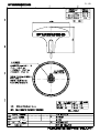
Dual GPS
DD-80
Your Local Agent/Dealer
9-52 Ashihara-cho,
Nishinomiya, Japan
Telephone :
0798-65-2111
Telefax :
0798-65-4200
All rights reserved.
Printed in Japan
FIRST EDITION : DEC. 1995
J
: APR. 01,2003
PUB.No. OME-43741
( TENI
) DD-80(GP-80-D)
*OME43741J00*
*OME43741J00*
*OME43741J0*
SAFETY INSTRUCTIONS
"DANGER", "WARNING" and "CAUTION" notices appear throughout this manual. It is the
responsibility of the operator and installer of the equipment to read, understand and follow
these notices. If you have any questions regarding these safety instructions, please contact a FURUNO agent or dealer.
DANGER
This notice indicates a potentially
hazardous situation which, if not
avoided, will result in death or
serious injury.
WARNING
This notice indicates a potentially
hazardous situation which, if not
avoided, could result in death or
serious injury.
CAUTION
This notice indicates a potentially
hazardous situation which, if not
avoided, could result in minor or
moderate injury, or property damage.
i
WARNING
Hazardous voltage.
Can shock.
Do not open the cover.
Only qualified personnel should
work inside the equipment.
CAUTION
Use the proper fuse.
Use of a wrong fuse can result in fire or
permanent equipment damage.
Power the equipment with the proper
power supply.
Powering the equipment with a wrong
power supply can cause permanent
equipment damage.
WARNING
Do not disassemble or modify the
equipment.
Fire, electrical shock or serious injury
can result.
Turn off the power immediately if
water leaks into the equipment, or
the equipment is emitting smoke or
fire.
Continued use of the equipment can
cause fire or electrical shock.
Do not place liquid-filled containers
on the top of the equipment.
Fire or electrical shock can result if a
liquid spills into the equipment.
Keep heater away from equipment.
Heat can alter equipment shape and melt
the power cord, which can cause fire or
electrical shock.
TABLE OF
CONTENTS
4.5 Erasing Route Waypoints.................. 4-6
4.6 Replacing Route Waypoints.............. 4-7
4.7 Erasing Routes .................................. 4-7
5. SETTING DESTINATION
FOREWORD ............................................ iii
SYSTEM OVERVIEW ............................. 1
1. OPERATIONAL OVERVIEW
1.1 Control Description .......................... 1-1
1.2 Turning On and Off the Power ......... 1-2
1.3 Adjusting Display Contrast and
Brilliance .......................................... 1-3
1.4 Display Mode ................................... 1-3
1.5 Transmitting Data ............................. 1-6
1.6 The Interface Unit ............................. 1-8
2. DISPLAY AND TRACK
2.1 Enlarging/Shrinking the Display ...... 2-1
2.2 Display Orientation........................... 2-1
2.3 The Cursor ........................................ 2-1
2.4 Shifting the Display .......................... 2-2
2.5 Centering Own Ship's Position ......... 2-2
2.6 Stopping/Starting Plotting and
Recording of Track ........................... 2-2
2.7 Erasing Track .................................... 2-3
2.8 Track Plotting Interval ...................... 2-4
2.9 Apportioning the Memory ................ 2-5
2.10 Bearing Reference .......................... 2-5
3. MARKS
3.1 Entering Marks ................................. 3-1
3.2 Erasing Marks ................................... 3-1
3.3 Mark Shape ....................................... 3-2
3.4 Connecting Marks ............................. 3-2
3.5 Entering Event Marks ....................... 3-2
3.6 Event Mark Shape ............................ 3-3
3.7 Entering the MOB Mark ................... 3-3
4. NAVIGATION PLANNING
4.1 Entering Waypoints........................... 4-1
4.2 Editing Waypoints............................. 4-4
4.3 Erasing Waypoints ............................ 4-4
4.4 Entering Routes ................................ 4-5
5.1 Setting Destination ........................... 5-1
5.2 Cancelling Destination...................... 5-5
5.3 Erasing Route Waypoints (flags) ...... 5-6
5.4 Finding Range and Bearing
Between Two Points ......................... 5-7
6. SETTING UP VARIOUS
DISPLAYS
6.1 The Data Display .............................. 6-1
6.2 Position Format................................. 6-2
6.3 Demo Display ................................... 6-4
7. ALARMS
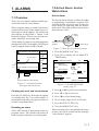
7.1 Overview .......................................... 7-1
7.2 Arrival Alarm, Anchor Watch Alarm 7-1
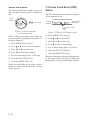
7.3 Cross Track Error (XTE) Alarm ....... 7-2
7.4 Speed Alarm ..................................... 7-3
7.5 Trip Alarm......................................... 7-3
7.6 Water Temperature Alarm ................. 7-4
7.7 Depth Alarm ..................................... 7-4
7.8 DGPS Alarm ..................................... 7-4
8. MENU SETTINGS
8.1 GPS Menu......................................... 8-1
8.2 Units of Measurement ...................... 8-3
8.3 Size and Brilliance of Markers ......... 8-4
8.4 Outputting Data ................................ 8-6
8.5 Receiving Data from Personal
Computer .......................................... 8-7
8.6 DGPS Settings .................................. 8-9
8.7 GPS Monitor Display ..................... 8-10
9. MAINTENANCE &
TROUBLESHOOTING
9.1 Clearing the Memory ........................ 9-1
9.2 Preventative Maintenance ................. 9-2
9.3 Error Messages ................................. 9-3
9.4 Troubleshooting ................................ 9-3
9.5 Diagnostic Tests ................................ 9-4
i
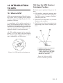
10. INTRODUCTION TO GPS
10.1 What is GPS? ................................ 10-1
10.2 How the GPS Receiver
Calculates Position........................ 10-1
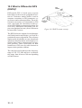
10.3 What is Differential
GPS (DGPS)? ............................... 10-2
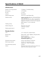
APPENDIX A
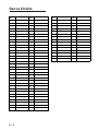
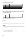
Specifications......................................... A-1
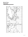
World Time Standards ........................... A-3
Geodetic Chart List ................................ A-4
Loran C Chains ...................................... A-5
Decca Chains ......................................... A-6
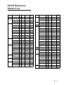
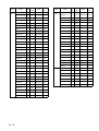
DGPS Reference Station List ................ A-7
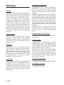
Glossary ............................................... A-10
APPENDIX B
INTERFACE UNIT IF-2500
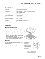
Specifications......................................... B-1
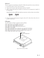
Installation ............................................. B-1
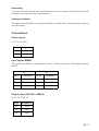
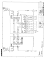
Connections ........................................... B-3
Maintenance........................................... B-4
ii
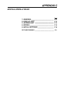
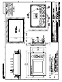
APPENDIX C
INSTALLATION OF GP-80-D
General................................................... C-1
Display Unit ........................................... C-2
Antenna Unit .......................................... C-3
Wiring .................................................... C-5
Initial Settings ........................................ C-6
Outline Drawings ................................... D-1
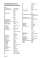
INDEX
FOREWORD
A Word to DD-80 Owners
Congratulations on your choice of the
FURUNO DD-80 dual differential GPS navigation system. We are confident you will see
why the FURUNO name has become synonymous with quality and reliability.
For over 50 years FURUNO Electric Company has enjoyed an enviable reputation for
innovative and dependable marine electronics equipment. This dedication to excellence
is furthered by our extensive global network
of agents and dealers.
This equipment is designed and constructed
to meet the rigorous demands of the marine
environment. However, no machine can perform its intended function unless operated and
maintained properly. Please carefully read and
follow the recommended procedures for operation and maintenance.
We would appreciate hearing from you, the
end-user, about whether we are achieving our
purposes.
Thank you for considering and purchasing
FURUNO equipment.
The main features of the DD-80 are
• Comprehensive navigation data displays
• Storage for 999 waypoints and 30 routes
• Alarms: Arrival, Anchor Watch, Crosstrack Error, Speed, Water Temperature,
Depth, and Trip
• Man overboard feature records latitude and
longitude coordinates at time of man overboard and provides continuous updates of
range and bearing to that point
• Menu-driven operation
• Bright 122 x 92 mm LCD with temperature compensated tone and brilliance adjustment
• Power consumption is a low 10 W per navigator.
• Connection of autopilot (option) – steering data output to autopilot
• Digital display of water temperature and
depth with connection of video sounder
having IEC 61162-1/NMEA input
• Memory stores 2,000 points of track and
marks
• 3D "Highway" display shows ship's track
overlaid on intended course
• Position may be shown in latitude and longitude or LOP (Loran or Decca)
• Navaid information (lighthouse data,
lighted buoys, etc.) can be displayed by
downloading database from personal computer.
Features
The DD-80 consists of two dual differential
GPS navigator systems and an interface unit.
Each GPS navigator consists of a display unit
combining a GPS receiver, beacon receiver
and video plotter, a GPS antenna and a beacon antenna. The interface unit functions to
exchange data between the GPS navigators
and external equipment. A high sensitivity
receiver tracks up to eight satellites simultaneously. An 8-state Kalman filter ensures optimum accuracy in determination of vessel
position, course and speed.
iii
This page is intentionally left blank.
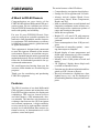
SYSTEM OVERVIEW
1. Menu Tree
Display selection menu
DISPLAY
SEL
Select Display (Plotter 1, Plotter 2, Highway, Navigation and Data displays)
Main menu
MENU
ESC
1. DISPLAY SETUP
2. TRACK/MARK SETUP
3. ERASE TRACK/MARK
4. ALARM SETTINGS 1/2
ALARM SETTINGS 2/2
5. MANUAL CALCULATION
6.
7. GPS MONITOR
SATELLITE MONITOR
BEACON RCVR MONITOR
STATION MESSAGE
8. SELF TESTS
1. MEMORY, I/O PORT TEST
2. KEYBOARD TEST
3. TEST PATTERN
4. AUTOMATIC TESTING
9. SYSTEM SETTINGS
1. PLOTTER SETUP
2. UNIT SETUP
3. DATA1, 3 OUTPUT SETUP
4. DATA TRANSFER
5. DATA4 I/O SETUP
6. GPS SETUP
DATA4 I/O SETUP 1/2 Out/COM./DGPS
DATA4 I/O SETUP "Out" 2/2
DATA4 I/O SETUP "Com." 2/2
DATA4 I/O SETUP "DGPS" 2/2
GPS SETUP 1/2
GPS SETUP 2/2
7. DGPS SETUP
8. LOP SETUP
9. CLEAR MEMORY
1
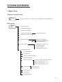
Waypoint, route menu
WPT
RTE
1. Cursor
2. MOB/Event Position
3. Own Ship Position
4. Waypoint List
5. Route Planning
WAYPOINT LIST
ROUTE LIST
GOTO menu
GOTO
1. Cursor
2. MOB/Event Position
3. Waypoint List
4. Route List
5. Cancel
2
GOTO "Waypoint List"
GOTO "Route List"
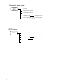
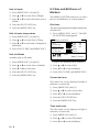
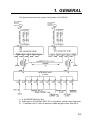
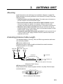
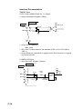
2. System Configuration
GP-80
GP-80
GPS
ANTENNA
GPA-017S/018S/019S
GPS
ANTENNA
GPA-017S/018S/019S
DISPLAY UNIT
GPR-020
DISPLAY UNIT
GPR-020
INTERFACE UNIT IF-2500
Position, waypoint, etc.
(RS-422/Current loop)
Position, etc.
(Current loop)
Arrival
alarm
Cross track
error alarm
Abnormal receiving
alarm
3
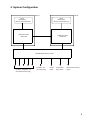
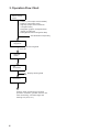
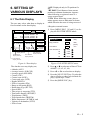
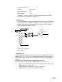
3. Operation Flow Chart
Select display
mode
• Plotter 1 (own ship's track and data)
• Plotter 2 (own ship's track)
• Highway (ship's track overlaid on
navigation lane)
• Navigation (graphic navigation data
display for steering)
• Data (alphanumeric navigation data)
Set destination temporarily
Register
waypoints
• By latitude and longitude
• By LOP
Register
routes
Set
destination
Display steering data
Set alarms
Perform other operations as required.
(Position correction, geodetic chart to use,
enter smoothing, calculate range and
bearing to a point, etc.)
4
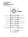
1. OPERATIONAL
OVERVIEW
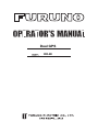
1.1 Control Description
Cursor keys
Shift display and
cursor.
Opens/closes menu;
quits current operation.
Selects display mode.
Registers waypoints
and routes.
Inscribes mark on
the display.
Expands display
range.
Centers ship's position/cursor
position.
Adjusts display contrast;
changes latitude/longitude
coordinate.
MENU
ESC
NU/CU
ENT
DISPLAY
1
SEL
EVENT
6
MOB
WPT
RTE
GOTO
MARK
ZOOM
IN
2
7
3
PLOT
ON/OFF 8
4
ZOOM
OUT
CENTER
5
TONE
Selects display orientation;
registers selections on menus.
9
CURSOR
ON/OFF 0
CLEAR
POWER
Inscribes event mark at
ship's position; marks man
overboard position
Sets destination.
Turns recording and plotting
of ship's track on/off.
Decreases display range.
Turns cursor on/off.
Deletes waypoints and marks;
clears wrong data; silences
audible alarm.
Turns power on/off.
Figure 1-1 Control panel
1–1
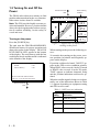
1.2 Turning On and Off the
Power
Several seconds A
later
The DD-80 takes about two minutes to find
position when turned on for the very first time.
Other times it takes about 20 seconds.
Note: The GPS provides highly accurate position information. However, position should
always be check against other aids to navigation to confirm reliability, for the safety of
vessel and crew.
135° 45.678´ E DGPS 3D
30
BRG
234°
[01]
CSE
40
50
H
123
WGS84
2nm
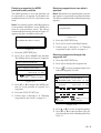
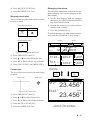
Press the [POWER] key.
The unit tests the PROGRAM MEMORY,
SRAM and battery for proper operation and
shows the results on the display. "BEACON
RCVR INSTALLED" appears at the bottom
of the display. The unit starts up with the last
used display mode and that mode is indicated
at the bottom of the display.
345°
RNG
20
Turning on the power
BEACON RCVR INSTALLED*
DATA #3 : LOG PULSE OUTPUT
SPD
12.3 kt
Figure 1-2 Appearance of display when
turning on the power
When turning on the power the following occurs:
20 seconds after turning on the power, accurate position (in latitude and longitude) appears on the display.
GPS receiving
condition
When the satellite signal is being received normally, one of the indications shown in Table
1-1 appears depending on equipment setting
and GPS receiver state.
Table 1-1 GPS receiver indication
Equipment GPS receiver state
setting
indication
1 - 2
nm
If position could not be found, "NO FIX" appears at the GPS receiver condition window.
When PDOP value exceeds 6 in the 3D mode
or HDOP value exceeds 4 in the 2D mode,
"DOP" appears to indicate abnormal fixing
and the position indication could not be updated.
PROGRAM MEMORY = OK
SRAM
= OK
Internal Battery
= OK
Several seconds A
later
34° 23.456´ N
GPS receiving
condition
2D
GPS 2D (normal)
3D
GPS 3D (normal)
Differential
2D
DGPS 2D (normal)
Differential
3D
DGPS 3D (normal)
Note 1: When PDOP value exceeds 6 in
the 3D mode, the position fixing method
is automatically changed to 2D.
Note 2: The "DEMO" icon appears when
the display is in the demonstration mode.
To return to normal mode, turn off the
power and turn it on while pressing and
holding down the [NU/CU ENT] key.
The next time you turn on the power the unit
starts up with the last used display mode.
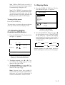
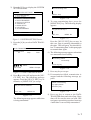
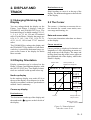
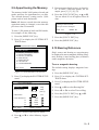
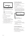
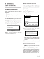
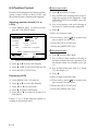
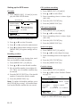
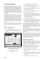
1.3 Adjusting Display
Contrast and Brilliance
1) Press the [TONE] key. The display shown
in Figure 1-3 appears.
[+]
MENU
:
Plotter 1
Plotter 2
MENU
4 (0~4)
:
Select
:
Escape
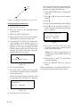
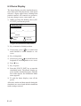
Figure 1-4 Screen for
selection of display mode
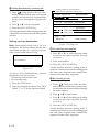
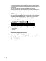
2) Press the [DISPLAY SEL] key, ▲ or ▼
to select display mode. (When the [DISPLAY SEL] key is pressed, the display
mode changes in sequence shown below.)
Selected display mode appears about 15
seconds later.
Plotter 1
8 (0~31)
Brilliance:
Select Display
Data
Press the [POWER] key.
Tone:
1) Press the [DISPLAY SEL] key. The display shown in Figure 1-4 appears.
Highway
Navigation
Turning off the power
[–]
1.4 Display Mode
Plotter 2
Data
Highway
Navigation
Sample displays of each display mode are
shown in the figures on the next several pages.
Escape
Figure 1-3 Screen for adjustment
of display contrast and brilliance
2) To adjust contrast, press t or s. Current setting and setting range (0–31) are
shown to the right of "s".
3) To adjust brilliance, press ▲ or ▼. Current setting and setting range (0–4) are
shown to the right of "▲".
Note: Operate cursor keys within 10
seconds after pressing the [TONE] key.
Otherwise, the screen for adjustment of
contrast and brilliance will be cleared.
1–3
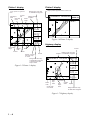
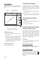
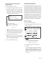
Plotter 1 display
Plotter 2 display
Bearing from own ship
to destination waypoint
Cursor position or lighthouse
data
Ship's position appears when cursor is off
Course
GPS receiving
Own ship's
bar
condition
track
Own ship
Alarm
mark
range
34° 23.456´ N
135° 45.678´ E DGPS 3D
30
[01]
34° 23.456´ N
135° 45.678´ E DGPS 3D
30
40
BRG
234°
[01]
50
H
CSE
40
50
H
345°
20
WGS84
2nm
BRG TO +
123°
Figure 1-6 Plotter 2 display
RNG TO +
20
11.5 nm
WGS84
2.0nm
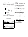
Highway display
Horizontal
range
Course
Grid
width
Course
Cursor
Course
Speed, or range
from own ship
to cursor
Bearing from own ship
Position to destination waypoint
Course
34° 23.456´ N
Range from own ship
to destination waypoint,
or bearing from own
ship to cursor
135° 45.678´ E DGPS 3D
[02]
BRG
234°
Figure 1-5 Plotter 1 display
CSE
H
345°
[01]
RNG
123 nm
SPD
2
North
mark
1
1
Own
ship
mark
Cross track
error scale
2
nm
12.3 kt
Course
Own
ship's
track
Course
Speed
width
Range from own ship
to destination waypoint
Figure 1-7 Highway display
1 -4
2) Autopilot connection, automatic mode
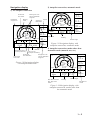
Navigation display
1) No autopilot connection
DGPS 3D
TO; 012
Cross track
error meter
Bearing from own
ship to destination
waypoint
Bearing
scale
Destination
waypoint no.
SPD
E
12.3 kt
Velocity To
Destination
N
Speed
VTD
BRG:
10.3 kt
63°
123°
CSE:
DGPS 3D
TO; 012
0.1nm
12.3 kt
N
0.1nm
ETA
Cross track
error scale
S
RNG
0.1nm
Cross track
error indication
TRIP
Str
Auto mode
Heading
123 nm
Rudder angle
Figure 1-9 Navigation display, with
autopilot connection, automatic mode
789 nm
Trip
distance
Time To Go
(3days17hrs45min)
123 nm
123° P 23° 789 nm
Auto
TRIP
TTG
Estimated Time of
Arrival (15th23:45)
Hdg
10.3 kt
3D
17H 45M
15
23:45'
Auto Pilot
VTD
BRG
63°
123°
RNG
0.1nm
SPD
E
CSE
S
3) Autopilot connection, modes other than
automatic mode (manual, nav, etc.)
Range from own
ship to destination
waypoint
TO; -
DGPS 3D
--
E
SPD
12.3 kt
N
Figure 1-8 Navigation display,
no autopilot connection
VTD
BRG:
10.3 kt
63°
123°
CSE:
0.1nm
Auto Pilot
Man
Man: Manual mode
Nav: Nav mode
Other:---
Hdg
S
AP CSE
0.1nm
Str
123°
TRIP
123° P 23° 789 nm
Heading
Rudder angle
Autopilot-set
course
Figure 1-10 Navigation display, with
autopilot connection, modes other than
the automatic mode
1–5
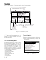
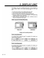
Data display
Data to display and size of characters can be selected by the operator.
Position in latitude and
longitude or LOPs
Fixing date and time*
Cursor
SEP 12, 1995 23:59'59" U
POSITION
WGS84
DGPS 3D
12° 23.456' N
123° 23.456' E
RNG
TO : 001
BRG
31.23 nm
CSE
SPD
12.3
223.4°
kt
MARINE
POINT1
NEXT
123.4°
User-defined
User-defined
display data #1 display data #4
: 002
MARINE
POINT2
Current destination waypoint
Next destination waypoint
User-defined
display data #3
User-defined
display data #2
User-defined
display window
Figure 1-11 Data display mode
*: "--" appears until calculating position after
turning on the power. If fixing error occurs
this indication stops.
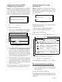
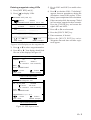
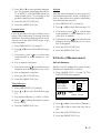
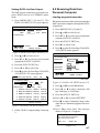
1.5 Transmitting Data
Transmitting data
To mutually transmit data, do the following:
1) Press the [MENU ESC] key to display the
MAIN menu.
MAIN MENU
The GPS navigators share the data listed below when transmitting data to each other. Any
action initiated against those data is automatically repeated on the other navigator. For example, if you register waypoint 27 on one
navigator it will be registered on the other
navigator under the same waypoint number.
• Alarm settings, alarm buzzer
• Destination data
• Disabled satellite data
• Error messages
• MOB/Event mark data
• Route data
• Waypoint data
1 - 6
1. DISPLAY SETUP
2. TRACK/MARK SETUP
3. ERASE TRACK/MARK
4. ALARM SETTINGS
5. MANUAL CALCULATION
6.
7. GPS MONITOR
8. SELF TESTS
9. SYSTEM SETTINGS
ENT: Enter
MENU: Escape
Figure 1-12 MAIN menu
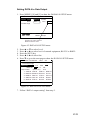
2) Press the [9] key to display the SYSTEM
SETTINGS menu.
Now transmitting data
SYSTEM SETTINGS
MENU: Stop
1. PLOTTER SETUP
2.
2. UNIT
UNIT SETUP
SETUP
3. DATA 1, 3 OUTPUT SETUP
4. DATA TRANSFER
5. DATA 4 I/O SETUP
6. GPS SETUP
7. DGPS SETUP
8. LOP SETUP
9. CLEAR MEMORY
ENT: Enter
Figure 1-16
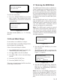
5) To stop transmitting data, press the
[MENU ESC] key. The following display
appears.
Are you sure to stop ?
MENU: Escape
ENT: Yes
Figure 1-13 SYSTEM SETTINGS menu
3) Press the [4] key to select DATA TRANSFER.
DATA TRANSFER
Transmit Data
All
Stop
Start
MENU: No
Figure 1-17
Press the [NU/CU ENT] key to stop. In
this case, data is partially transmitted to
the other GPS navigator. You should follow "Transmsitting data" in this paragraph
to transmit data again.
6) The following message appears when data
was transmitted successfully.
Transmitting ended
successfully
Press any key
: Select
ENT: Enter
MENU: Escape
Figure 1-14 DATA TRANSFER menu
4) Press s to select All and press the [NU/
CU ENT] key. The following message
appears. Press the [NU/CU ENT] key to
transmit, or [MENU ESC] to escape.
Are you sure to transmit ?
ENT: Yes
MENU: No
Figure 1-15
The following message appears while data
is being transmitted.
Figure 1-18
7) Press any key to escape.
8) If transmission failed, transmission is
stopped and the following message appears.
Failed in transmitting
Try again please
Press any key
Figure 1-19
9) Press any key to return to the DATA
TRANSFER menu and select Stop. Since
data will be not the same on both GPS
navigator, repeat this procedure from step
4 until data is successfully transmitted.
1–7
Transmission failure during
operation
Data is transmitted only once. When transmission error occurs, the following message
appears.
Failed in transmitting
Try "DATA TRANSFER" menu
Press any key
Figure 1-20
Press any key to erase the message. Follow
"Transmitting data" in this paragraph to transmit data again.
1–8
1.6 The Interface Unit
The Interface Unit IF-2500 outputs data received from the navigators to external equipment. Operational status is shown by the LEDs
on the unit. For further details, see APPENDIX B of this manual. For how to select data
to output, see paragraph 8.4 Outputting Data.
Output data conventions
Since both navigators output data to the IF2500 (through two ports on the interface) confusion would reign if it were to try to output
two sets of mostly identical data. Therefore,
data output is governed by the following rules:
• When both navigators are outputting data
correctly, data received at the port having
higher priority is output.
• When the GPS abnormal receive signal is
received at the port having higher priority,
data received from the other port is output.
• 30 seconds after data received at the port
having higher priority becomes normal,
the interface resumes outputting data received from that port.
• When data from both navigators is in error, data received at the port having higher
priority is output.
• Arrival alarm signal or cross track error
alarm is converted to a contact signal and
output when received at the port having
higher priority.
• When no data is received from one or both
navigators, a contact signal is output.
2. DISPLAY AND
TRACK
2.1 Enlarging/Shrinking the
Display
You may enlarge/shrink the display on the
Plotter 1 and Plotter 2 displays, with the
[ZOOM IN] and [ZOOM OUT] keys. The
horizontal range is available among 0.25, 0.5,
1, 2, 4, 8, 16, 32, 64, 128 and 192 nautical
miles. For the Plotter 1 display the ranges are
0.36, 0.71, 1.42, 2.84, 5.69, 11.38, 22.76,
45.51, 91.02, 182.04 and 273.07 nautical
miles.
The [ZOOM IN] key enlarges the display and
the [ZOOM OUT] key shrinks it. Each time a
zoom key is pressed the horizontal range appears at the center of the display for about
three seconds.
2.2 Display Orientation
Destination not set
Ship's heading or course is at the top of the
display. The north mark appears at the left side
of the display.
2.3 The Cursor
The cursor (+) functions to measure the select location for a mark; erase marks, measure range and bearing, etc.
Data and cursor state
Cursor state determines what data are shown
on the display.
Cursor turned on
Cursor position is displayed in latitude and
longitude or LOPs (depending on menu setting) at the top of the display. The range and
bearing from own ship to the cursor appear at
the right hand side of the display, when in the
Plotter 1 display.
Cursor mark
Display orientation can be selected on the
Plotter 1, Plotter 2 and Highway displays, with
the [NU/CU ENT] key. Two display orientations are available: north-up and course-up.
30° 22.321´ N
Cursor position in
latitude and longitude
139° 43.543´ E DGPS 3D
BRG
234°
North-up display
CSE
345°
In the north-up display, true north (0°) is at
the top of the display. Own ship moves on the
display in accordance with true speed and true
motion. Land is stationary.
BRG To +
123°
RNG To +
WGS84
2.0nm
11.5 nm
Course-up display
Destination set
Cursor
The destination is at the top of the display and
the north mark ( ) appears at the left side of
the display.
Range from own
ship to cursor
Bearing from own
ship to cursor
Figure 2-1 Data displayed
when the cursor is on
2 - 1
Cursor turned off
2.4 Shifting the Display
Ship's position (in latitude and longitude or
LOPs), speed and course appear on the display.
The display can be shifted on the Plotter 1
and Plotter 2 displays, with the [CURSOR
ON/OFF] key. When own ship tracks off the
display it is automatically returned to the
screen center.
Own ship
mark
Own ship position
in latitude and longitude
34° 23.456´ N 135° 45.678´ E
1) Press the [CURSOR ON/OFF] key to turn
off the cursor.
DGPS 3D
2) Press the cursor keys. The display shifts
in the direction of the cursor key pressed.
BRG
234°
CSE
345°
2.5 Centering Own Ship's
Position
RNG
123
SPD
1) Press the [CURSOR ON/OFF] key to turn
off the cursor.
12.3 kt
2) Press the [CENTER] key.
nm
Course
Speed
Figure 2-2 Data displayed
when the cursor is turned off
Shifting the cursor
1) Press the [CURSOR ON/OFF] key to turn
on the cursor.
2) Press the cursor keys to shift the cursor.
The cursor moves in the direction of the
cursor key arrow pressed. When the cursor reaches the edge of the display, the
display shifts in the direction opposite of
the cursor key pressed.
Centering the cursor
Press the [CENTER] key.
2.6 Stopping/Starting Plotting
and Recording of Track
The DD-80 stores 2,000 points of track and
marks. When the memory becomes full the
oldest track is erased to make room for the
latest. Thus you may want to conserve the
memory when, for example, you are returning to port or are anchored, by stopping plotting and recording of the track.
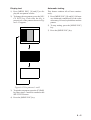
Procedure
Press the [PLOT ON/OFF] key to start/stop
recording and plotting of track.
When plotting is resumed
"Resuming track plot" appears at the center
of the display for about three seconds.
When plotting is stopped
"Stopping track plot" appears at the center of
the display for about three seconds and " H "
appears at the left side of the display. (" H "
does not appear on the Navigation and Data
displays.)
2–2
2.7 Erasing Track
Hold icon
(appears while recording
of track is stopped)
34° 23.456´ N 135° 45.678´ E
The track stored in the memory and displayed
on the screen can be erased.
DGPS 3D
Note: Track cannot be restored once erased.
Be absolutely sure you want to erase track.
BRG
234°
CSE
345°
H
RNG
123
nm
SPD
12.3 kt
This portion of track
does not appear on
the display
Own ship
1) Press the [MENU ESC] key. The MAIN
MENU appears.
MAIN MENU
1. DISPLAY SETUP
2. TRACK/MARK SETUP
3. ERASE TRACK/MARK
4. ALARM SETTINGS
5. MANUAL CALCULATION
6.
7. GPS MONITOR
8. SELF TESTS
9. SYSTEM SETTINGS
ENT: Enter
Recording of
track started
Ship’s track
while recording is
stopped
Recording of track
turned off
Figure 2-3 Track not plotted or
recorded when plotting is stopped
MENU: Escape
Figure 2-4 MAIN menu
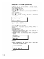
2) Press [3] to select ERASE TRACK/
MARK.
ERASE TRACK/MARK
Erase Track
No
Yes
Erase Mark
No
Yes
Track Pts. Used:
345/1000 Pt
Mark Pts. Used:
123/1000 Pt
: Select
MENU: Escape
Figure 2-5 ERASE TRACK/MARK menu
3) Press ▲ or ▼ to select Erase Track.
4) Press s to select Yes. The message shown
in Figure 2-6 appears.
2–3
3) Press ▲ or ▼ to select Track Rec.
Are you sure to erase ?
ENT: Yes
4) Press t to select Time.
MENU: No
Figure 2-6 Prompt for
erasure of track, mark
5) Press the [NU/CU ENT] key.
5) Enter plotting interval in four digits. To
enter 30 seconds, for example, press [0]
[0] [3] [0].
6) Press the [NU/CU ENT] key.
7) Press the [MENU ESC] key.
Plotting interval by distance
2.8 Track Plotting Interval
The plotting interval determines both how the
track will be reconstructed on the display and
track storage time. A shorter interval provides
more accurate reconstruction of track line,
however total storage time is reduced. The
plotting interval can be selected by time or
distance. Plotting by distance offers the advantage that the track is not stored when the
vessel is anchored.
The setting range for plotting by time is 00 to
60 minutes.
1) Press the [MENU ESC] key.
2) Press [2] to display the TRACK/MARK
SETUP menu.
TRACK/MARK SETUP
Time
(01'00)
Dist
(00.50nm)
Mark Shape
Mark Line
Event Mark
: Select
ENT: Enter
MENU: Escape
Figure 2-7 TRACK/MARK SETUP menu
2–4
1) Press the [MENU ESC] key.
2) Press [2] to display the TRACK/MARK
SETUP menu.
3) Press ▲ or ▼ to select Track Rec.
4) Press s to select Distance.
5) Enter plotting interval. To enter 0.1 nautical miles, for example, press [0] [0] [1].
Plotting interval by time
Track Rec
The setting range for plotting by distance is
0.01 to 99.99 nautical miles. To plot all track,
enter 00.00.
6) Press the [NU/CU ENT] key.
7) Press the [MENU ESC] key.
2.9 Apportioning the Memory
The memory holds 2,000 points of track and
marks and may be apportioned as you like.
The default memory setting stores 1,000
points each of track and marks.
Note: All data are erased when the memory
apportion setting is changed, even when the
previous value is reentered.
To store 1,500 points of track and 500 marks,
for example, do the following:
5) Enter amount of track to store, in four digits. To store 1,500 track points, for example, press [1] [5] [0] [0].
6) Press the [NU/CU ENT] key, or ▲ or ▼.
You are asked if it is all right to erase all
data.
Setting erases all data!
Are you sure to change ?
ENT: Yes
MENU: No
Figure 2-10
1) Press the [MENU ESC] key.
7) Press the [NU/CU ENT] key.
2) Press [9] to display the SYSTEM SETTINGS menu.
8) Press the [MENU ESC] key.
SYSTEM SETTINGS
2.10 Bearing Reference
1. PLOTTER SETUP
2.
2. UNIT
UNIT SETUP
SETUP
3. DATA 1, 3 OUTPUT SETUP
4. DATA TRANSFER
5. DATA 4 I/O SETUP
6. GPS SETUP
7. DGPS SETUP
8. LOP SETUP
9. CLEAR MEMORY
ENT: Enter
Ship's course and bearing to waypoint may
be displayed in true or magnetic bearing. Magnetic bearing is true bearing plus (or minus)
earth's magnetic deviation.
True or magnetic bearing
MENU: Escape
Figure 2-8 SYSTEM SETTNGS menu
The default setting displays magnetic bearings.
1) Press the [MENU ESC] key.
3) Press [1] to display the PLOTTER SETUP
menu.
2) Press [9] to display the SYSTEM SETTINGS menu.
PLOTTER SETUP
Memory Apportion
Trk = 1000 / 2000Pt
3) Press [1] to display the PLOTTER SETUP
menu.
Bearing Ref.
True
Mag Variation
Auto
(07° W)
Calculation
R.L
User defined #1
RNG
User defined #2
SPD
User defined #3
BRG
User defined #4
CSE
ENT: Enter
Mag
Man
(00° E)
G.C
4) Press ▲ or ▼ to select Bearing Ref.
5) Press t or s to select True or Mag.
6) Press the [NU/CU ENT] key, ▲ or ▼.
7) Press the [MENU ESC] key.
MENU: Escape
Figure 2-9 PLOTTER SETUP menu
4) Press ▲ or ▼ to select Memory Apportion.
2–5
Magnetic variation
The location of the magnetic north pole is different from the geographical north pole. This
causes a difference between the true and magnetic north direction. This difference is called
magnetic variation, and varies with respect to
the observation point on the earth. Magnetic
variation may be entered automatically or
manually.
1) Press the [MENU ESC] key.
2) Press [9] to display the SYSTEM SETTINGS menu.
3) Press [1] to display the PLOTTER SETUP
menu.
4) Press ▲ or ▼ to select Mag Variation.
5) Press t or s to select Auto or Man. For
automatic, current variation appears in parentheses.
6) For manual entry, enter variation in two
digits, referring to a nautical chart. If the
variation is 10°, for example, press [1] [0].
7) If necessary, press the [ ] key to change
coordinate from east to west or vice versa.
8) Press the [NU/CU ENT] key.
9) Press the [MENU ESC] key.
2–6
3. MARKS
At cursor intersection
1) Press the [CURSOR ON/OFF] key to turn
on the cursor.
3.1 Entering Marks
Marks can be inscribed on the Plotter 1 and
Plotter 2 displays, in one of 12 mark shapes.
Further, marks can be connected with lines to
denote net location, etc.
Note 1: When the mark memory becomes full
no marks can be entered. When this occurs,
the buzzer sounds and the message shown below appears on the display for three seconds.
To enter a mark when the mark memory is
full, erase unnecessary marks.
Can't save mark
Memory full
2) Operate the cursor keys to place the cursor on the location for the mark.
3) Press the [MARK] key.
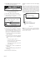
3.2 Erasing Marks
Marks can be erased individually or collectively.
Note: All marks, including event marks and
the MOB mark, can be erased on the ERASE
MARK menu. Be absolutely sure you want
to erase all marks; erased marks cannot be
restored.
Erasing individual marks
Figure 3-1
Note 2: Marks cannot be entered when there
is no position data. When this occurs, the
buzzer sounds and the message shown below
appears on the display for three seconds to
alert you. Check the antenna cable for tight
connection.
1) Place cursor on the mark to erase.
2) Press the [CLEAR] key.
Erasing all marks
1) Press [MENU ESC] and [3] to display the
ERASE TRACK/MARK menu.
ERASE TRACK/MARK
Can't save mark
No position data
Figure 3-2
Erase Track
No
Yes
Erase Mark
No
Yes
Track Pts. Used:
345/1000 Pt
Mark Pts. Used:
123/1000 Pt
Entering marks
At own ship position
1) Press the [CURSOR ON/OFF] key to turn
off the cursor.
2) Press the [MARK] key.
: Select
MENU: Escape
Figure 3-3 ERASE TRACK/MARK menu
2) Press ▲ or ▼ to select Erase Mark.
3) Press s to select YES.
3–1
3.4 Connecting Marks
Are you sure to erase ?
ENT: Yes
MENU: No
Figure 3-4
Marks can be connected with lines to denote
net location, fishing spot, etc. Three types of
connection lines are available and the "•" setting disables connection of lines.
4) Press the [NU/CU ENT] key.
1) Press [MENU ESC] and [2]
5) Press the [MENU ESC] key.
2) Press ▲ or ▼ to select Mark Line.
3) Press t or s to select mark line desired.
3.3 Mark Shape
4) Press the [NU/CU ENT] key.
12 mark shapes are available. Select mark
shape as follows:
5) Press the [MENU ESC] key.
1) Press [MENU ESC] and [2] to display the
TRACK/MARK SETUP menu.
3.5 Entering Event Marks
TRACK/MARK SETUP
Track Rec
Time
(01'00)
Dist
(00.50nm)
Event marks can denote any important present
position; for example, a good fishing spot. 99
event marks can be saved, and the unit automatically numbers them from 01 to 99.
Mark Shape
Event marks are mutually entered when the
navigators are sharing data.
Mark Line
Note 1: When the mark memory becomes full
no event marks can be entered. When this occurs, the buzzer sounds and the message
shown below appears on the display for three
seconds to alert you. To enter an event mark
when the mark memory is full, erase unnecessary event marks.
Event Mark
: Select
ENT: Enter
MENU: Escape
Figure 3-5 TRACK/MARK SETUP menu
2) Press ▲ or ▼ to select Mark Shape.
3) Press t or s to select mark shape desired.
Can't save event
Memory full
4) Press the [NU/CU ENT] key.
Figure 3-6
5) Press the [MENU ESC] key.
Note 2: Event marks cannot be entered when
there is no position data. When this occurs,
the buzzer sounds and the message shown
below appears on the display for three seconds to alert you. Check the antenna cable for
tight connection.
The next mark entered will be inscribed in
the shape selected here.
3–2
3.7 Entering the MOB Mark
Can't save event/MOB
No position data
Figure 3-7
To enter an event mark;
1) Press the [EVENT MOB] key less than
three seconds. The position at the exact
moment the key is pressed is saved as an
event position.
Saved event position
34°40.123’ N
135°21.123’ E
Figure 3-8
To erase event marks, see "3.2 Erasing
Marks".
3.6 Event Mark Shape
The MOB mark denotes man overboard position. To mark man overboard position, press
the [EVENT MOB] key. When the key is
pressed, the position at the exact moment the
key is pressed automatically becomes the destination. Further, the Plotter 1 display replaces
the display in use when it is other than a plotter display.
Only one MOB mark may be entered. Each
time the MOB mark is entered the previous
MOB mark and its position data are written
over. The MOB mark is mutually entered
when the navigators are sharing data.
Note: The MOB mark cannot be entered
when there is no position data. When this occurs, the buzzer sounds and the message
shown below appears on the display for three
seconds to alert you. Check the antenna cable
for tight connection.
Can't save event/MOB
No position data
Event marks are available in 9 shapes.
Event mark shape is mutually changed when
the navigators are sharing data.
Select event mark shape as follows.
1) Press [MENU ESC] and [2] to display the
TRACK/MARK SETUP menu.
2) Press ▲ or ▼ to select Event Mark.
3) Press t or s to select event mark shape
desired.
4) Press the [NU/CU ENT] key.
5) Press the [MENU ESC] key.
The next event mark entered will be inscribed
in the shape selected here.
Figure 3-9
1) Press the [EVENT MOB] key for at least
three seconds.
The MOB mark ("M") is entered at the
MOB position and the message shown in
Figure 3-10 appears.
Saved MOB position
Are you sure to change course
to MOB position ?
ENT: Yes
MENU: No
Figure 3-10
2) Press the [NU/CU ENT] key. If the display in use is Highway, Navigation or
Data, they are automatically replaced by
the Plotter 1 display.
Note: You may cancel MOB position as destination by pressing the [MENU ESC] key
instead of the [NU/CU ENT] key at step 2.
Note that the MOB mark remains on the display.
3–3
Erasing the MOB mark
See "3.2 Erasing Marks". (MOB marks cannot be erased with the cursor.) The MOB mark
is mutually erased when the navigators are
sharing data.
3–4
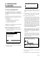
4. NAVIGATION
PLANNING
Place cursor on desired location
ENT: Enter
MENU: Escape
Figure 4-2
4.1 Entering Waypoints
In navigation terminology a waypoint is a
particular location on a voyage whether it be
a starting, intermediate or destination
waypoint.
The DD-80 can store 999 waypoints, numbered from 001–999. Waypoints can be registered four ways:
• by cursor
• by MOB position or event position
• at own ship's position, and
• through the waypoint list.
Waypoints are mutually entered when the
navigators are sharing data.
Entering waypoints by the cursor
1) Press the [WPT RTE] key. The Waypoint/
Route menu appears.
Waypoint/Route
1. Cursor
2. MOB/Event Position
3. Own ship Position
4. Waypoint List
5. Route Planning
The display changes to Plotter 2 when the
Highway, Navigation or Data mode is in
use.
3) Press the cursor keys to place the cursor
on the location desired for the waypoint.
4) Press the [NU/CU ENT] key.
A window similar to the one shown in Figure 4-3 appears. The waypoint's position
and date and time registered appear on the
first and second lines. Waypoints are automatically given the youngest empty
waypoint number and this number appears
on the third line. You may, however, assign a different number. If the waypoint
shares the same position with a mark, the
mark's position and date and time entered
are registered as waypoint data.
If the waypoint memory is full, the
waypoint number line in the window is
blank. In this case waypoints cannot be
entered unless a waypoint is written over
or erased.
To assign waypoint number, go to step 5.
If you do not want to change the waypoint
number, go to step 6 to select mark shape
and enter comment.
30° 12.345' N 135° 23.456' W
AUG 12’ 95 12 : 34U
: Cursor
ENT: Enter
MENU: Escape
No. : 1
123
Mark :
Cmnt :
Figure 4-1 Waypoint/Route menu
: Cursor
2) Press [1] to select Cursor. The following
display appears.
ENT: Enter
: Column
MENU: Escape
Figure 4-3
5) Enter waypoint number, in three digits
(001–999).
6) Press ▼ to select waypoint mark shape.
4–1
6) Press ▼ to select waypoint mark shape.
The following display appears.
: Cursor
ENT: Enter
MENU: Escape
Figure 4-4 Screen for selecting
waypoint mark shape
7) Press t or s to select mark shape.
8) Press the [NU/CU ENT] key. The display
shown in Figure 4-5 appears.
Control is returned to the last used display
mode.
When the waypoint number entered at step 5
already exists, the message shown in Figure
4-4 appears if the waypoint is part of the current destination or route or is part of a route.
If it is you are sure to write over the waypoint
and its data, press the [Y] key. To change
waypoint number, press the [N] key.
1st line
Are you sure to change ?
ENT: Yes
MENU: No
A
ABCDE FGHIJ KLMNO PQRST UVWXYZ
abcde
fghij
klmno
pqrst
uvwxyz
1234567890 _#%’()+-./:;<=>?
ENTER
COMMENT: _
: Cursor
ENT: Set
___________
MENU: Escape
Figure 4-5 Screen for entry
of comment for waypoint
9) You may enter a comment, as shown in
the procedure which follows, or skip to
step 10 to finish. The comment may consist of up to 12 alphanumeric characters.
1 Press the cursor keys to select alphanumeric character.
2 Press the [NU/CU ENT] key. Selected
character appears on the COMMENT
line.
• To create a space, select "_".
• Numeric data can be input directly
by pressing numeric keys.
• To clear wrong data, press the
[CLEAR] key.
3 Repeat steps 1 and 2 to complete the
comment.
4 Select ENTER and press the [NU/CU
ENT] key.
10) Press the [NU/CU ENT] key.
4–2
This wpt is GOTO
This wpt is in registered route
This wpt is in selected route
Figure 4-6
Note: If you fail to enter waypoint number,
"Enter waypoint number" appears on the display for three seconds.
Entering waypoints by MOB
position/event position
Entering waypoints at own ship's
position
The MOB position or an event position can
be registered as a waypoint. Event marks are
numbered from 01 to 99; 01 is the latest event
mark.
Note: When there is no position data, you cannot register a waypoint at own ship's position.
The buzzer sounds and the following message
appears.
Note: You cannot register a MOB position or
event position when there are no MOB positions or event positions saved. The buzzer
sounds and the message shown in Figure 4-7
appears for three seconds to alert you.
No position data
Figure 4-9
No MOB/event data in memory
1) Press the [WPT/RTE] key.
2) Press [3] to select Own Ship Position.
Figure 4-7
3) Follow steps 5 through 11 in "Entering
waypoints by the cursor" on page 4-1.
1) Press the [WPT/RTE] key.
2) Press [2] to select MOB/Event Position.
The display shown in Figure 4-8 appears.
Entering waypoints through the
waypoint list
1) Press the [WPT/RTE] key.
[MOB] Displaying MOB data
34° 12.345' N 130° 23.456' E
AUG 12' 94 19 : 25U
[#01] Displaying event data
:Recall
34° 12.345'
N 130° 23.456' E
ENT:Enter
AUG
12' 95 19 : 25U
MENU:Escape
: Paging
ENT: Enter
MENU: Escape
Figure 4-8
2) Press [4] to display the waypoint list.
3) Press [ ] to select position format; latitude and longitude or LOP.
WAYPOINT LIST (L/L)
001 34° 12.345' N 130° 23.456' W
MARINE POINT AUG 12' 95 12 : 35U
002
36° 12.345' N 135° 23.456' W
3) Press t or s to display the MOB position or event position to register as a
waypoint.
003
°
.
'N
°
.
'W
4) Press the [NU/CU ENT] key.
004
°
.
'N
°
.
'W
5) Follow steps 5 through 11 in "Entering
waypoints by the cursor" on page 4-1.
AUG 13' 95 13 : 45U
A POINT
: L/L´LOP
ENT: Enter
: Edit
MENU: Escape
Figure 4-10
4) Press ▲ or ▼ to select waypoint number.
5) Press t or s to enter position. The display should now look something like Figure 4-11.
4–3
4.2 Editing Waypoints
Edit = Waypoint : 001
_ _° _ _._ _ _' N _ _ _°_ _._ _ _' W
Waypoints are mutually edited when the navigators are sharing data.
Mark : __
Cmnt :
1) Press [WPT RTE] and [4].
: Cursor
ENT: Enter
2) Press ▲ or ▼ to select waypoint to edit.
: Column
MENU: Escape
3) Press s.
4) Edit the contents of the waypoint.
Figure 4-11
6) Enter latitude and longitude. To enter
34°12.345' N 135°23.456' E, for example,
press;
([
]) [3] [4] [1] [2] [3] [4] [5]
([
]) [1] [3] [5] [2] [3] [4] [5] [6]
To change N to S or E to W, press [
].
7) Press ▼.
5) Press the [NU/CU ENT] key. The message shown in Figure 4-12 appears if the
waypoint is currently selected as destination, is part of a route, or is in the route
currently selected as destination.
1st line
Are you sure to erase ?
ENT: Yes
MENU: No
8) Press t or s to select mark.
9) Press the [NU/CU ENT] key.
10) Enter comment.
11) Press the [NU/CU ENT] key twice.
The waypoint list reappears. Waypoint
position and date and time the waypoint
was entered appear on the list.
12) To enter another waypoint through the
waypoint list, return to step 4.
13) Press the [MENU ESC] key to finish.
This wpt is GOTO
This wpt is in registered route
This wpt is in selected route
Figure 4-12
6) Press the [NU/CU ENT] key.
The waypoint and its data are erased. Enter new data, referring to "4.1 Entering
Waypoints".
7) Press the [MENU ESC] key.
4.3 Erasing Waypoints
Waypoints are mutually erased when the navigators are sharing data.
Erasing waypoints by the cursor
1) Place the cursor on the waypoint to erase.
2) Press the [CLEAR] key.
4–4
Erasing waypoints through the
waypoint list
1) Press [WPT RTE] and [4].
2) Press ▲ or ▼ to select waypoint to erase.
3) Press the [CLEAR] key. The message
shown in Figure 4-13 appears if the
waypoint is currently selected as destination, is part of a route, or is in the route
currently selected as destination.
1st line
Are you sure to erase ?
ENT: Yes
MENU: No
4.4 Entering Routes
Often a trip from one place to another involves
several course changes, requiring a series of
route points which you navigate to, one after
another. The sequence of waypoints leading
to the ultimate destination is called a route.
The DD-80 can automatically advance to the
next waypoint on a route, so you do not have
to change the destination waypoint repeatedly.
The DD-80 can store 30 routes and each route
may contain up to 30 waypoints. Routes can
be registered while in the Plotter 1 or Plotter
2 display mode. Routes are mutually registered when the navigators are sharing data.
Entering routes
1) Press the [WPT/RTE] key.
This wpt is GOTO
This wpt is in registered route
This wpt is in selected route
Figure 4-13
Note: All waypoint marks (as well as all
other marks) and their data can be erased
collectively by clearing the Plotter
memory. For further details, see page 9-1.
4) Press the [NU/CU ENT] key.
Note: To cancel erasure, press the [MENU
ESC] key instead of the [NU/CU ENT]
key. The waypoint list appears.
5) Press the [MENU ESC] key.
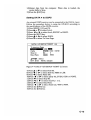
2) Press [5] to select Route Planning. The
route list appears.
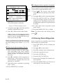
ROUTE LIST
No. PTS Total Dist.
TTG
Remarks
01 30 1234 . 56 nm 12D15H28M UseFwd
02 25
234 . 56 nm 2D08H35M
03 30 *999. 99 nm *9D*9H*9M
.
nm
04
D H M
05 30 6543 . 21 nm 34D23H45M
.
nm
06
D H M
: Route No.
ENT: Enter
: Edit
MENU: Escape
Remarks
Use: In use
Fwd: Traverse waypoints in forward order
Rvs: Traverse waypoints in reverse order
Figure 4-14 Route list
3) Press ▲ or ▼ to select route number.
4) Press s.
The route planning/waypoint list window
appear as shown in Figure 4-15. The
waypoint list window lists the position and
data for each registered waypoint. No position or data appears for empty
waypoints.
4–5
2 Using previously registered waypoints
ROUTE : 01 (In Use , REVERSE)
skip Distance TTG
Trial Speed : Auto
01
EN
EN
02
001
Man (012.0kt)
. nm D M
. nm D M
H
H
Route
editing
screen
34° 12.345' N 130° 23.456' E
MARINE POINT AUG 12' 95 12 : 35U
002 36° 12.345' N 135° 23.456' E
AUG 13' 95 13 : 45U
A POINT
: RTE
WPT CLEAR: Delete
ENT: Enter MENU: Escape
Waypoint
list
Use: In use
Fwd: Traverse waypoints in forward order
Rvs: Traverse waypoints in reverse order
Figure 4-15 Route editing screen
5) If required, press ▲ to enter the speed by
which to calculate time-to-go.
6) Press t or s to select Auto or Man.
Auto: Current average speed is used to
calculate the time-to-go. Manual: Entered
speed is used to calculate the time-to-go.
Enter speed and press ▼.
Route waypoints may be registered two ways:
entering waypoint number directly or through
the route editing screen. Follow 1 or 2 below.
1 Entering waypoint number directly
7) Enter waypoint number, in three digits.
The cursor shifts to the "Skip" window.
The procedure for skipping a waypoint is
shown on page 5-4. For now, go to the
next step.
8) Press ▼ to continue. If the waypoint entered in step 7 does not exist, you are informed that the waypoint does not exist
and entry is cancelled.
9) Enter other route waypoints by repeating
steps 7 and 8.
10) Press [MENU ESC] to finish.
4–6
Enter waypoints in the order they will be traversed; not by waypoint number order.
7) Press [ ]. The reverse video on the
waypoint on route planing screen disappears.
8) Press ▲ or ▼ to select waypoint number.
9) Press the [NU/CU ENT] key. Selected
waypoint number appears on the route
editing screen. The distance and time-togo indications to the first waypoint entered
are blank.
10) To enter other route waypoints, repeat
steps 8 and 9.
11) Press the [MENU ESC] key to finish.
Note: To return to the route editing screen,
press [ ].
4.5 Erasing Route Waypoints
Route waypoints are mutually erased when
the navigators are sharing data.
1) Press [WPT RTE] and [5] to display the
route list.
2) Press ▲ or ▼ to select route.
3) Press s to display route editing screen.
4) Select the waypoint to erase.
5) Press the [CLEAR] key.
6) Press the [NU/CU ENT] key.
7) Repeat steps 2 through 4 to continue erasing waypoints.
8) Press the [MENU ESC] key. The route is
rearranged to reflect the change.
4.6 Replacing Route
Waypoints
Route waypoints are mutually replaced when
the navigators are sharing data.
1) Press [WPT RTE] and [5] to display the
route list.
2) Press ▲ or ▼ to select route.
3) Press s to display route editing screen.
4) On the route editing screen, place the cursor on waypoint number to replace.
5) Enter new waypoint number.
6) Press the [NU/CU ENT] key. The message shown in Figure 4-16 appears.
This waypoint already exists
Are you sure to change ?
ENT: Yes
MENU: No
Figure 4-16
7) Press the [NU/CU ENT] key.
4.7 Erasing Routes
Routes are mutually erased when the navigators are sharing data.
1) Press [WPT RTE] and [5] to display the
route list.
2) Press ▲ or ▼ to select route to erase.
3) Press the [CLEAR] key. The display
shown in Figure 4-17 appears if the route
is in use.
1st line
Are you sure to erase ?
ENT: Yes
MENU: No
This route is in use
Figure 4-17
4) Press the [NU/CU ENT] key.
5) Press the [MENU ESC] key.
8) Press the [MENU ESC] key twice.
4–7
This page is intentionally left blank.
5. SETTING
DESTINATION
5.1 Setting Destination
There are four ways by which you can set
destination:
• By cursor
• By MOB position or event position
• By waypoint, and
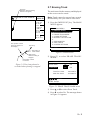
• By route.
The same destination is set on both navigators when they are sharing data.
Note 1: Destination cannot be set when there
is no GPS position data. When there is no position data, the buzzer sounds and the message shown in Figure 5-1 appears.
No position data
Setting destination by cursor
Using the cursor you may set a destination
consisting of 30 points. When all 30 points
are entered, the DD-80 automatically disables
further entry.
Setting single destination
1) Press the [GOTO] key. The menu shown
in Figure 5-2 appears.
GOTO Setting
1. Cursor
2. MOB/Event Position
3. Waypoint List
4. Route List
5. Cancel
: Cursor
ENT
: Enter
MENU : Escape
Figure 5-2 GOTO setting menu
2) Press [1] to select Cursor. The display
shown in Figure 5-3 appears.
Figure 5-1
Note 2: Previous destination is cancelled
whenever a destination is set.
Place cursor on desired location
Press ENT twice to finish
ENT:Enter CLR:Clear MENU:Escape
Figure 5-3
If the display in use is other than Plotter
1, the Plotter 2 display is automatically
selected.
3) Place the cursor on the location desired
for destination.
4) Press the [NU/CU ENT] key.
Note: To clear selection, press the
[CLEAR] key.
5) Press the [NU/CU ENT] key to finish.
Control is returned to the display mode in use
before you set destination. A dashed line connects own ship and the destination, which is
marked with a flag, as shown in Figure 5-4.
5–1
Flag
mark
The waypoints do not have waypoint numbers, however you can attach waypoint
numbers by doing the following.
1 Press [WPT RTE] and [5] to display the
route list.
Figure 5-4 Single destination set by cursor
2 Press ▲ or ▼ to select route number
entered.
3 Press s.
Setting multiple destinations
4 Enter waypoint number, in three digits.
1) Press [GOTO] and [1].
5 Press ▼. If the waypoint number already exists the message shown in Figure 5-7 appears.
2) Place the cursor on the location desired
for waypoint.
3) Press the [NU/CU ENT] key.
4) Repeat steps 2 and 3 to enter other points.
Waypoints are connected with a line.
5) Press the [NU/CU ENT] key to finish. The
route number entry display appears as
shown in Figure 5-5. If no route number
appears or you want to change the route
number shown, go to step 6 to enter route
number. To register the route under the
number shown, go to step 8.
Enter route number
01
ENT:Enter MENU: Escape
Figure 5-5
6) Key in route number.
7) Press the [NU/CU ENT] key. Waypoints
are marked with flags and are connected
with a dashed line.
If the route number entered already exists
the message shown in Figure 5-6 appears.
Overwriting ?
ENT:Yes MENU:No
Figure 5-6
8) Press the [NU/CU ENT] key.
5–2
This waypoint already exists
Are you sure to change ?
ENT:Yes MENU:No
Figure 5-7
6 Press the [NU/CU ENT] key. The
waypoint entered here replaces previously entered waypoint.
Note: To cancel replacement of
waypoint, press the [MENU ESC] key
at step 6.
7 Repeat steps 4 and 5 to enter other
waypoint numbers.
8 Press the [MENU ESC] key twice to
finish.
When destination is cancelled, dashed lines
are erased but flags remain on the screen.
Setting destination by MOB
position or event position
Setting destination through
waypoint list
Note: This operation cannot be performed
when there is no MOB position or event position. The buzzer sounds and the message
shown in Figure 5-8 appears to alert you when
there is no MOB position or event position.
Note: A waypoint must exist to set it as destination. When a waypoint does not exist, the
buzzer sounds and the message shown in Figure 5-10 appears.
No waypoint data
No MOB/event data in memory
Figure 5-10
Figure 5-8
1) Press the [GOTO] key.
2) Press [2] to select MOB/Event Position.
The display shown in Figure 5-9 appears.
Destination waypoint can be set through the
waypoint list two ways:
• By entering waypoint number, and
• By selecting waypoint by cursor
1) Press the [GOTO] key.
[MOB] Displaying MOB data
34° 12.345' N 130° 23.456' E
AUG 12' 94 19 : 25U
[#01] Displaying event data
:Recall
34° 12.345'
N 130° 23.456' E
ENT:Enter
AUG
12' 95 19 : 25U
MENU:Escape
: Paging
ENT: Enter
MENU: Escape
2) Press [3] to display the Waypoint List.
GOTO (Waypoint List)
Waypoint
Waypoint No.
No.
001 34° 12.345' N 132° 23.456' E
MARINE POINT AUG 12' 95 12:35U
002 ° 12.345' N 133° 12.345' E
Figure 5-9
3) Press t or s to select MOB position or
event position. The MOB position appears
first. To select event position, press s. If
selected position is within the current display range, the cursor marks the position.
(The cursor does not appear on the Highway, Navigation and Data displays.)
4) Press the [NU/CU ENT] key. A flag appears at position selected if it is within the
current display range. A dashed line connects between own ship and MOB position or event position.
When destination is cancelled, dashed lines
are erased but flags remain on the screen.
A POINT
AUG 13' 95 13:28U
005 41° 34.567' N 135° 23.456' E
B POINT
No
.
AUG 14' 95 09:45U
List
ENT:Enter
Waypoint number can be entered here
when this line appears in reverse video.
Figure 5-11 Waypoint list
Set destination by following 1 or 2 below.
1 Setting destination by waypoint no.
3) Enter waypoint number, in three digits.
You can clear entry by pressing the
[CLEAR] key.
4) Press the [NU/CU ENT] key.
Own ship position becomes starting point and
a dashed line runs between it and the waypoint
selected.
5–3
2 Setting destination by selecting wpt.
Route number can be entered here
when this line appears in reverse video.
3) Press [ ]. Each press of the key alternately enables manual entry of waypoint
number and selection of waypoint number by cursor (through the waypoint window).
Route No.
01
4) Press ▲ or ▼ to select waypoint.
5) Press the [NU/CU ENT] key.
Own ship position becomes starting point and
a dashed line runs between it and the waypoint
selected.
GOTO (Route List)
No. PTS
tFORWARD s
TOTAL
TTG
30
1234. 56nm
12D15H28M
02
25
234. 56nm
2D08H35M
05
8
57. 89nm
0D10H28M
06
30
*999. 99nm *9D23H59M
10
30
6543. 21nm
: No.
34D23H45M
List
ENT:Enter
MENU:Escape
Setting route as destination
Note: Route entered must exist to set it as
destination. The buzzer sounds and the message shown in Figure 5-12 appears if you set
enter a route which does not exist.
No route data
Figure 5-13 Route list
1 By entering route number
3) Press t or s to select direction which
to traverse the route waypoints; forward
or reverse.
4) Enter route number.
5) Press the [NU/CU ENT] key.
Figure 5-12
A route to set as destination may selected
through the route list two ways:
• By entering route number, and
• By selecting route.
1) Press the [GOTO] key.
2) Press [4] to display the Route List. Then,
follow 1 or 2 in the adjacent column.
Current position becomes starting point. A
solid line connects between the starting point
and first route waypoint and a dashed line
connects all other route waypoints.
2 By selecting a route
]. Each press of the key alter3) Press [
nately enables manual entry of route number and selection of route number (through
the route window)
4) Press ▲ or ▼ to select route.
5) Press t or s to select direction in which
to traverse the route waypoints; forward
or reverse.
6) Press the [NU/CU ENT] key.
Current position becomes starting point. A
solid line connects between the starting point
and first route waypoint and a dashed line
connects all other route waypoints.
5–4
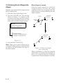
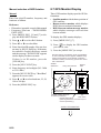
Skipping route waypoints
You may skip route waypoints by displaying
"DI" (DIsable) next to the route waypoint in
the route list. Using Figure 5-14 as an example, your ship is currently heading toward
waypoint 04 but is to switch course and head
to waypoint 03. In this case you would want
to skip waypoint 04.
,,
,,
,,
,,
,,,
,,,
,,,
,,,
Waypoint 03
Waypoint 04
4) Press [ ] to change "EN"(ENable) to
"DI"(DIsable).
5) Press the [NU/CU ENT] key.
Route waypoints are mutually skipped when
the navigators are sharing data.
New course
Waypoint 05
Waypoint 06
Port B
3) Press t or s to shift the cursor to the
right of the waypoint number.
To reselect the waypoint, select it on the route
list and press [ ] to change "DI" to "EN".
Waypoint 01
Waypoint 02
Port A
2) Press ▲ or ▼ to select route waypoint to
skip.
5.2 Cancelling Destination
Destination is cancelled at both GPS navigators when they are sharing data.
Figure 5-14
1) Press [WPT RTE] and [5] to display the
route list. Press the cursor keys to select
route.
"EN" indicates waypoint
is enabled. Display "DI"
to skip waypoint.
1) Press the [GOTO] key.
2) Press [5] to select Cancel. The message
shown in Figure 5-16 appears.
Release GOTO ?
ENT:Yes
ROUTE
(In Use, REVERSE)
:01
skip Distance
TTG
001 Speed Auto Man (012.0kt)
Trial
01 0 04 EN
nm
D M H
02 0 03 EN 345.67nm
2D 12H 34M
004
34° 12.345' N 130° 23.456' E
MARINE POINT APR 10' 95 12:35U
003
36° 12.345' N
A POINT
: RTE
ENT:Enter
MENU:No
WPT
Figure 5-16
3) Press the [NU/CU ENT] key.
135° 23.456' E
APR 10' 95 13:45U
CLEAR: Delete
MENU:Escape
Figure 5-15 Route list
5–5
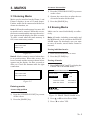
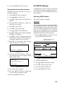
5.3 Erasing Route Waypoints
(flags)
Flags are erased at both GPS navigators when
they are sharing data.
1) Place the cursor on the flag to erase.
2) Press the [CLEAR] key. The message
shown in Figure 5-17 appears if the
waypoint is currently selected as destination, is part of a registered route, or is part
of the route currently being navigated.
1st line
Are you sure to erase ?
ENT:Yes MENU:No
This wpt is GOTO
This wpt is in registered route
This wpt is in selected route
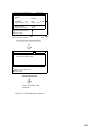
When flags are erased
When the origin waypoint is erased the
waypoint before it becomes the origin
waypoint. If there is no waypoint before the
origin waypoint, current position becomes the
origin waypoint.
Delete
Starting
point
Destination
waypoint
Course
Own
ship
Destination
waypoint
Figure 5-17
3) Press the [NU/CU ENT] key.
Note: Flags can be erased collectively by
clearing the Plotter memory or both the Plotter memory and GPS memory. See page 9-1
for further details.
Figure 5-18 Route rearranged
after erasing flag
When a destination is erased, the waypoint
which follows it becomes the destination. If
there is no waypoint after the destination
waypoint erased, route navigation is cancelled.
5–6
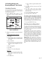
5.4 Finding Range and
Bearing Between Two Points
Calculation Procedure
You can find the range and bearing between
two points by two waypoints or two latitude
and longitude positions.
1) Press [MENU ESC] and [5]. The
MANUAL CALCULATION menu appears.
MANUAL CALCULATION
From Waypoint No.
° .
’N
°
To
Waypoint No.
° .
’N
°
Trial speed : Auto
Man
(
.
Rng :
. m
Brg :
TTG: D H M
: Cursor
ENT : Calculation
.
’E
.
’E
kt)
. °
MENU : Escape
: N/S, E/W
Figure 5-19 MANUAL
CALCULATION menu
2) Choose two points by one the methods
below.
Latitude and longitude positions
1) Press ▼.
2) If necessary press to switch from
North latitude and to South latitude
vice versa.
3) Key in latitude.
4) If necessary press to switch from West
longitude to East longitude and vice
versa.
3) Key in other waypoint number (000999).
3) Press ▼ to shift the cursor to the Trial
Speed line.
4) Press t or s to select Auto or Man.
Auto uses ship's average speed to calculate time-to-go.
5) If you selected Man, enter speed.
6) Press the [NU/CU ENT] key.
The range, bearing and time-to-go between
two points appear on the display. If data entered is wrong or insufficient the buzzer
sounds and the message "INCOMPLETE
DATA" appears. If the data contains error, "*"
and all nines appear as the calculation results.
7) Press the [MENU ESC] key.
Selecting course sailing method
The range and bearing to a destination are calculated by two ways; Great Circle or Rhumb
Line. However, cross track error is calculated
by rhumb line only.
Great Circle: The great circle courseline is
the shortest course between two points on the
surface of the earth. (Imagine stretching a
piece of yarn between two points on the earth.)
However, this course requires frequent change
of heading to follow course faithfully.
Rhumb Line: The rhumb line courseline is
the straight line drawn between two points on
a nautical chart. This course does not require
frequent changes of heading however it is not
the shortest since it follows the earth's curvature.
5) Key in longitude.
6) Press ▼.
7) Repeat 2-5 to enter other point.
Waypoints
1) Key in first waypoint number (000999). (000 is reserved for own ship
position.)
2) Press ▼ twice.
5–7
1) Press [MENU ESC] [9] and [1] to display the PLOTTER SETUP menu.
PLOTTER SETUP
Memory Apportion
Trk = 1000 / 2000Pt
Bearing Ref.
True
Mag Variation
Auto
(07° W)
Calculation
R.L
User defined #1
Man
(00° E)
G.C
User defined #2
SPD
CRS
User defined #3
RNG
User defined #4
BRG
ENT:Enter
Mag
MENU:Escape
Figure 5-20 PLOTTER SETUP menu
2) Press ▲ or ▼ to selection Calculation.
3) Press t or s to select R.L (Rhumb Line)
or G.C (Great Circle).
4) Press the [NU/CU ENT] key.
5) Press the [MENU ESC] key.
5–8
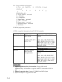
6. SETTING UP
VARIOUS DISPLAYS
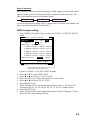
6.1 The Data Display
The user may select what data to display in
four locations on the data display.
SEP 12, 1995 23:59'59" U
POSITION
WGS84
DGPS 3D
12° 23.456' N
123° 23.456' E
RNG
SPD
NEXT
CSE
12.3
123.4°
kt
User-defined
display data #1
User-defined
display data #2
MARINE
POINT1
223.4°
31.23 nm
: 002
MARINE
POINT2
User-defined
display data #3
User-defined
display data #4
User-defined
display window
Figure 6-1 Data display
The data the user may display are;
• Altitude (ALT)*
• Average course (AVR CSE)
• Average speed (AVR SPD)
• Course (CSE)
• Course error (dCSE)
• Cross track error (XTE)
• Depth (W.DPT)#
• ETA to waypoint (ETA)
• Range to waypoint (RNG)
• Route time-to-go (RT.TTG)
• Speed (SPD)
• Time-to-go to waypoint (TTG)
• Total route distance (RT.DIST)*
• Trip distance (TRIP)
• Trip elapsed time (TRIP TM)
• Water temperature (W.TMP)#, and
• Velocity to destination (VTD)*
• ETA to route
# Requires external sensor.
1) Press [MENU ESC] [9] and [1] to display the PLOTTER SETUP menu.
PLOTTER SETUP
Memory Apportion
Trk = 1000 / 2000Pt
TO : 001
BRG
*ALT: Displayed only in 3D position fixing.
*RT. DIST: Total distance from current
position to ultimate destination. Appears
when following a registered route or a
cursor-created route.
*VTD: When following a route, plus or
minus appears next to indication to denote
which direction the route is being traversed.
Bearing Ref.
True
Mag Variation
Auto
(07° W)
Calculation
Mag
Man
(00° E)
R.L
User defined #1
SPD
User defined #2
CSE
User defined #3
RNG
User defined #4
BRG
ENT:Enter
MENU:Escape
G.C
Figure 6-2 PLOTTER SETUP menu
2) Press ▲ or ▼ to select one of four of "User
defined" (#1, #2, #3, #4).
3) Press t or s to select data to display.
4) Press the [NU/CU ENT] key. To select the
data to display at other user defined displays, repeat steps 2 and 3.
5) Press the [MENU ESC] key.
6 – 1
6.2 Position Format
1 For Loran LOPs
Position can be displayed in latitude and longitude, Loran C LOPs, or Decca LOPs, and
the default format is latitude and longitude.
6) Press ▼ to select LC Chain.
Selecting position format (L/L or
LOPs)
1) Press [MENU ESC] [9] and [8] to display the LOP SETUP menu.
8) Key in secondary code pair referring to
the Loran C chain list in the Appendix.
9) Press ▼.
10) Key in correction value.
LOP SETUP
Lat / Long
Pos Display
LOP
LOP Display
LC
DE
LC Chain
7980 : 23-43
LOP
-12.3us +0.34 us
DE Chain
24:G - P
LOP
+0.80 Lane -1.00 Lane
(RED:1 GREEN:2 PURPLE:3)
: Select
MENU : Escape
7) Key in GRI code referring to the Loran C
chain list appears in the Appendix. If the
GRI code is 9970, for example, press [9]
[9] [7] [0].
ENT : Enter
: +/–
Figure 6-3 LOP SETUP menu
2) Press ▲ or ▼ to select Pos Display.
3) Press t or s to select Lat/Long or LOP.
4) Press the [NU/CU ENT] key.
11) If necessary, press [ ] to switch from
plus to minus or vice versa.
12) Press the [NU/CU ENT] key.
13) Press the [MENU ESC] key.
2 For Decca LOPs
6) Press ▼ to select DE Chain.
7) Key in Decca chain number referring to
the Decca chain list in the Appendix. For
the Europe chain, for example, press [0]
[1].
8) Key in Decca lane pair. Red, [1]; Green
[2], and Purple [3].
9) Press ▼.
Displaying LOPs
10) Key in lane correction value.
1) Press [MENU ESC] [9] and [8].
2) Press ▲ or ▼ to select Pos Display.
11) If necessary, press [ ] to switch from
plus to minus or vice versa.
3) Press t or s to select LOP.
12) Press the [NU/CU ENT] key.
4) Press ▼ to select LOP Display.
13) Press the [MENU ESC] key.
5) Press t or s to select LC (Loran C) or
DE (Decca).
Follow 1 or 2 in the adjacent column according to selection in step 5.
6–2
Entering waypoints using LOPs
1) Press [WPT RTE] and [4].
6) Press ▼ to calculate LOPs. "Calculating"
appears between parentheses during the
calculation. Actual LOPs replace "Calculating" upon completion of the calculation.
] to display LOPs.
2) Press [
WAYPOINT LIST (LOP, LC)
001 36365.2
59102.3
MARINE POINT AUG12' 95 12 : 35U
002 36512.3
___ A POINT
59134.5
AUG13'
95 13 : 45U
003 _ _ _ _ _ , _
_____,_
___ _ _ _ _ _ _ _ _ _ _ _ _
004 _ _ _ _ _ , _
_____,_
___ _ _ _ _ _ _ _ _ _ _ _ _
: L/L
LOP
: Edit
MENU : Escape
ENT : Enter
5) Key in LOP1 and LOP2, to enable calculation.
Figure 6-4 LOP display on the waypoint list
If the conversion fails, the message "Failed
in Conversion" appears for three seconds.
Press the [CLEAR] key and reenter the
right LOP1 and LOP2.
7) Press t or s to select mark.
8) Press the [NU/CU ENT] key.
9) Enter comment, if desired.
10) Press the [NU/CU ENT] key twice.
Waypoint data and date and time registered appear.
3) Press ▲ or ▼ to select waypoint number.
4) Press t or s. Your display should look
like one of the displays in Figure 6-5.
Edit=Waypoint : 001
LC8930 :
30
50
58654.3
33 8931.2
(34° 12.345' N 130° 23.456' E)
Mark :
Cmnt : MARINE POINT
: Cursor
ENT : Enter
: Column
MENU : Escape
Loran C LOP input screen
Edit=Waypoint : 001
DE : 32 (9C) RED
GREEN
11 A:12.23
2H:24.35
(34° 12.345' N 130° 23.456' E)
Mark :
Cmnt : MARINE POINT
ABCDEFGHIJ fi 1, 2 ~ 9, 0
: Cursor
: Column
ENT : Enter
MENU : Escape
Decca LOP input screen
Figure 6-5 LOP input screens
6–3
6.3 Demo Display
The demo display provides simulated operation of this unit. Own ship tracks, at the speed
selected, a figure eight course, starting from
position entered. All controls are operative;
you may change course, enter marks, etc.
1) While pressing and holding down [NU/
CU ENT], turn on the power.
DEMO SETTING
BASE POSITION
_ _° _ _._ _ _' N _ _ _°_ _._ _ _' W
SPEED
00.00kt
: Cursor
ENT: Enter
: Column
: N/S, E/W
Figure 6-6 Simulation mode menu
2) Key in latitude of initial position.
3) If necessary, press [ ] to switch from
north latitude to south latitude or vice
versa.
4) Key in longitude.
5) If necessary, press [ ] to switch from east
longitude to west longitude or vice versa.
6) Press ▼ key.
7) Key in speed.
8) Press the [NU/CU ENT] key to start the
simulation mode. The plotter display appears and the simulation begins. After the
test results appear, the Simulation Mode
menu appears.
9) To quit the demo display, turn off the
power.
All tracks, marks and data entered during the
simulation are erased and default simulation
mode settings restored.
6–4
7.2 Arrival Alarm, Anchor
Watch Alarm
7. ALARMS
Arrival alarm
7.1 Overview
There are seven alarm conditions which generate both aural and visual alarms.
When an alarm setting is violated, the buzzer
sounds and the name of the alarm being violated appears on the display. The alarm icon
also appears on the Plotter 1, Plotter 2 and
Highway displays. This occurs on both navigators when they are sharing data.
Alarm status is output to external equipment
through the DATA1 port and the DATA4 port
when it outputs data in NMEA format.
The arrival alarm informs you that own ship
is approaching a destination waypoint. The
area that defines an arrival zone is that of a
circle which you approach from the outside
of the circle. The alarm will be released if own
ship enters the circle.
Alarm
setting
Own ship's
position
Destination
waypoint
: Alarm range
Figure 7-2 How the arrival alarm works
34° 23.456´ N 135° 45.678´ E
Alarm message
DGPS 3D
1) Press the [MENU ESC] key.
BRG
2) Press [4] to display the ALARM SETTINGS menu.
234°
CSE
345°
Alarm
icon
Arrival alarm
Speed alarm
Press CLEAR to silence beep
RNG
123
nm
SPD
12.3 kt
Press
CLEAR
ALARM SETTINGS
Arrival/Anchor
Alarm Range
XTE
Alarm Range
Ship Speed
Speed Rage
Next Page
1/2
Arr.
Anc.
Off
0.100nm
On
Off
0.050nm
Over
In
Over Off
000.0 ~ 025.0kt
: Select
Press CLEAR to close window
Figure 7-1 Location of alarm
messages and alarm icon
Clearing the aural and visual alarms
ENT : Enter
MENU : Escape
Figure 7-3 ALARM SETTINGS
menu, page 1/2
3) Press ▲ or ▼ to select Arrival/Anchor.
4) Press t or s to select Arr.
Press the [CLEAR] key. When the navigators
are sharing data, the "reset alarm signal" is
transmitted to the other navigator to clear aural and visual alarms there.
Disabling an alarm
Select OFF instead of alarm name on the appropriate menu. This disables the alarm on
both navigators when they are sharing data.
5) Press ▼ to select Alarm Range.
6) Key in alarm range (0.001–9.999 nm).
7) Press the [NU/CU ENT] key.
8) Press the [MENU ESC] key.
When own ship nears a waypoint by the range
set here, the buzzer sounds and the message
"Arrival alarm" appears.
7–1
Anchor watch alarm
The anchor watch alarm sounds to warn you
that own ship is moving when it should be at
rest.
Alarm
setting
Own ship's
position
: Alarm range
Destination
waypoint
7.3 Cross Track Error (XTE)
Alarm
The XTE alarm warns you when own ship is
off its intended course.
Starting
waypoint
Own ship's
position
Alarm
setting
Destination
waypoint
: Alarm range
Figure 7-4 How the anchor
watch alarm works
Before setting the anchor watch alarm, set
present position as destination waypoint, referring to chapter 5.
Figure 7-5 How the XTE alarm works
1) Press [MENU ESC] and [4].
2) Press ▲ or ▼ to select XTE.
3) Press t or s to select On.
1) Press [MENU ESC] and [4].
4) Press ▼ to select Alarm Range.
2) Press ▲ or ▼ to select Arrival/Anchor.
5) Key in alarm range (0.001–9.999 nm).
3) Press t or s to select Anc.
6) Press the [NU/CU ENT] key.
4) Press ▼ to select Alarm Range.
7) Press the [MENU ESC] key.
5) Key in alarm range (0.001–9.999 nm).
6) Press the [NU/CU ENT] key.
7) Press the [MENU ESC] key.
When own ship drifts by the range set here,
the buzzer sounds and the message "Anchor
alarm" appears.
7–2
When own ship strays from the intended track
by the range set here, the buzzer sounds and
the message "Cross track error alarm" appears.
7.4 Speed Alarm
7.5 Trip Alarm
The speed alarm sounds when ship's speed is
lower or higher (or within) the alarm range
set.
The trip alarm sounds when the distance run
is greater than the trip alarm setting.
1) Press [MENU ESC] and [4].
2) Press ▲ or ▼ to select Next Page. The
menu shown in Figure 7-6 appears.
2) Press ▲ or ▼ to select Ship Speed.
3) Press t or s to select In or Over.
1) Press [MENU ESC] and [4].
ALARM SETTINGS
5) Key in low speed.
To Previous Page
Trip (CLR:Reset)
Trip Range
Water Temp.
Temp. Range
Depth
Depth Range
DGPS Alarm
6) Key in high speed.
: Select
MENU : Escape
In: Alarm sounds when speed is within
range set.
Over: Alarm sounds when speed is higher
or lower than range set.
4) Press ▼ to select Speed Range.
2/2
Off
On
0123.00nm
In
Over Off
+12.0 ~ +15.0°C
In
Over Off
0003.0 ~ 0200.0ft
Off
On
ENT : Enter
: +/-
7) Press the [NU/CU ENT] key.
8) Press the [MENU ESC] key.
When speed is higher or lower (or within) than
the speed set here, the buzzer sounds and the
message "Speed alarm" appears.
Figure 7-6 Alarm settings menu, page 2/2
3) Press ▲ or ▼ to select Trip.
4) If necessary, press [CLEAR] to reset the
trip distance and trip elapsed time.
5) Press t or s to select On.
6) Press ▼ to select Trip Range.
7) Key in trip range.
8) Press the [NU/CU ENT] key.
9) Press the [MENU ESC] key.
When the ship's distance run is higher than
the trip range set here, the buzzer sounds and
the message "Trip alarm" appears.
7–3
7.6 Water Temperature Alarm
7.7 Depth Alarm
The water temperature alarm sounds when the
water temperature is higher or lower (or
within) the preset temperature. This alarm requires a temperature signal from external
equipment.
The depth temperature alarm sounds when the
depth is higher or lower (or within) the preset
depth. This alarm requires video sounder connection.
1) Press [MENU ESC] and [4].
2) Press ▲ or ▼ to select Depth.
2) Press ▲ or ▼ to select Water Temp.
3) Press t or s to select In or Over.
4) Press ▼ to select Temp. Range.
5) Key in low temperature.
6) Key in high temperature.
7) Press the [NU/CU ENT] key.
8) Press the [MENU ESC] key.
When the water temperature is higher or lower
(or within) the preset value, the buzzer sounds
and the message "Water temp alarm" appears.
1) Press [MENU ESC] and [4].
3) Press t or s to select In or Over.
4) Press ▼ to select Depth Range.
5) Key in low depth.
6) Key in high depth.
7) Press the [NU/CU ENT] key.
8) Press the [MENU ESC] key.
When the depth is higher or lower (or within)
the preset value, the buzzer sounds and the
message "Depth alarm" appears.
7.8 DGPS Alarm
The DGPS alarm sounds when the DGPS signal is lost. This alarm may be enabled or disabled as below.
1) Press [MENU ESC] and [4].
2) Press ▲ or ▼ to select DGPS Alarm.
3) Press t to select On, or sto select off.
4) Press the [NU/CU/ENT] key.
5) Press the [MENU ESC] key.
7–4
8. MENU SETTINGS
8.1 GPS Menu
Menu description
Fix mode
Two position fixing modes are available: 2D
and 2/3D. The 2D mode provides two dimensional position fixes (latitude and longitude
only) and is used when three satellites are in
line of sight of the GPS receiver.
The 2/3D mode switches between two and
three dimension position fixing automatically
depending on how many satellites (three or
four) are in light of sight of the GPS receiver.
Disable satellite
Every GPS satellite is broadcasting abnormal
satellite number(s) in the Almanac. Using this
information, the GPS receiver automatically
eliminates any malfunctioning satellite from
the GPS satellite schedule. However, the Almanac sometimes may not contain this information. You can disable an inoperative
satellite manually on the GPS SETUP menu.
may change randomly depending on receiving conditions and other factors. You can reduce this random variation by increasing the
smoothing. Like with latitude and longitude
smoothing, the higher the speed and course
smoothing the more smoothed the raw data.
If the setting is too high, however, the response
to speed and course change slows. For no
smoothing, enter "0." "5" is suitable for most
conditions.
Speed average
Calculation of ETA and TTG, etc. is based on
average ship’s speed over a given period. The
default setting is one minute.
Geodetic datum
Select the geodetic chart system you are using. WGS-84 (standard GPS chart system) and
NAD 27 can be directly selected. For other
charts, select "OTHER" and enter chart number referring to the geodetic chart list in the
Appendix.
Position offset
You may apply an offset to position generated by the internal GPS receiver, to compensate for difference between GPS position and
chart position.
GPS smoothing, position
Time difference
When the DOP or receiving condition is unfavorable, the GPS fix may change greatly,
even if the vessel is dead in water. This change
can be reduced by smoothing the raw GPS
fixes. A setting between 0 and 9 is available.
The higher the setting the more smoothed the
raw data, however too high a setting slows
response time to change in latitude and longitude. This is especially noticeable at high
ship’s speeds. "0" is the normal setting; increase the setting if the GPS fix changes
greatly.
The GPS system uses UTC time. If you would
rather use local time, enter the difference in
hours between local time and UTC. Use the
[+] and [–] keys for times later or earlier than
UTC, respectively.
Position
Enter ship's position when cold starting (no
satellite information in memory) the GPS receiver, to fix position faster. Accuracy should
be within 10°.
GPS smoothing, speed
During position fixing, ship’s velocity (speed
and course) is directly measured by receiving
GPS satellite signals. The raw velocity data
8–1
Setting up the GPS menu
GPS position smoothing
Fix mode
1) Press [MENU ESC] [9] and [6].
1) Press [MENU ESC] [9] and [6] to display the GPS SETUP menu.
GPS SETUP
Fix mode
Disable satellite
GPS Smoothing
Posn
Spd
Speed Average
To Next Page
2D
12
1/2
2/3D
(1-32)
0 0 0 (000-999 sec)
0 0 5 (000-999 sec)
01 minute
: Select
MENU : Escape
ENT : Enter
Figure 8-1 GPS SETUP menu, page 1/2
2) Press ▲ or ▼ to select Fix mode.
2) Press ▲ or ▼ to select Posn.
3) Enter smoothing factor in three digits
(001–999).
4) Press the [NU/CU ENT] key.
5) Press the [MENU ESC] key.
GPS speed smoothing
1) Press [MENU ESC] [9] and [6].
2) Press ▲ or ▼ to select Spd.
3) Enter smoothing factor in three digits
(001–999).
4) Press the [NU/CU ENT] key.
5) Press the [MENU ESC] key.
3) Press t or s to select fix mode desired.
4) Press ▼ to change other settings, or press
[MENU ESC] to register settings and escape.
Speed averaging
1) Press [MENU ESC] [9] and [6].
2) Press ▲ or ▼ to select Speed Average.
Disabling satellites
When the navigators are sharing data, satellites are disabled on both navigators.
3) Enter smoothing factor in two digits (00–
99).
4) Press the [NU/CU ENT] key.
1) Press [MENU ESC] [9] and [6].
5) Press the [MENU ESC] key.
2) Press ▲ or ▼ to select Disable satellite.
Geodetic datum
3) Key in satellite number, in two digits (01–
32). Three sets of satellite numbers may
be entered.
4) Press the [NU/CU ENT] key. If an invalid
number is entered the buzzer sounds.
5) Press the [MENU ESC] key.
Note: To enable all disabled satellites, press
the [CLEAR] key at step 3. All satellite numbers on the Disable satellite line are erased.
1) Press [MENU ESC] [9] and [6].
2) Press ▲ or ▼ to select Geodetic Datum
on page 2/2.
GPS SETUP
2/2
To Previous Page
Geodetic Datum WGS84 NAD27 OTHER
(005)
Posn Offset
0.000' N 0.000' E
Time Diff.
+09: 00
Posn
12° 36.789' N 112° 47.890' E
: Select
MENU : Escape
ENT : Enter
: +/—
Figure 8-2 GPS SETUP menu, page 2/2
8–2
3) Press t or s to select geodetic datum to
use. For geodetic datum other than WGS72 or NAD-27, select OTHER and key in
chart number (001–171) referring to the
geodetic chart list in the Appendix.
Position
4) Press the [NU/CU ENT] key.
After the unit is installed you may enter position to shorten the time it takes to find position. (It takes about two minutes when there
is no position data entered.)
5) Press the [MENU ESC] key.
1) Press [MENU ESC] [9] and [6].
Position offset
If you do not know the type of chart you are
using, GPS position may be wrong. Note the
difference in position when moored to a pier
and enter it on the GPS SETUP menu, to get
correct position.
1) Press [MENU ESC] [9] and [6].
2) Press ▲ or ▼ to select Posn Offset on page
2/2.
2) Press ▲ or ▼ to select Posn on page 2/2.
3) If necessary, press [ ] to switch from
north latitude to south latitude or vice
versa. Key in latitude.
4) If necessary, press [ ] to switch from east
longitude to west longitude or vice versa.
Key in longitude.
5) Press the [NU/CU ENT] key.
6) Press the [MENU ESC] key.
3) If necessary press [ ] to switch from
north latitude to south latitude or vice
versa.
8.2 Units of Measurement
4) Key in latitude correction.
Unit of distance
5) If necessary press [ ] to switch from east
longitude to west longitude or vice versa.
Distance can be displayed in nautical mile,
kilometer or statute mile as follows.
6) Key in longitude correction.
1) Press [MENU ESC] [9] and [2]. The
UNIT SETUP menu appears.
7) Press the [NU/CU ENT] key.
8) Press the [MENU ESC] key.
Time difference
1) Press [MENU ESC] [9] and [6].
UNIT SETUP
Unit of Distance
nm
km
sm
Unit of Depth
Unit of Temp.
Unit of Altitude
m
°C
ft
°F
FA
m
ft
2) Press ▲ or ▼ to select Time Diff on page
2/2.
3) Key in time difference (–14:00 to +14:00).
4) Press [ ] to change from plus to minus
or vice versa.
5) Press the [MENU ESC] key.
: Select
ENT : Enter
MENU : Escape
Figure 8-3 UNIT SETUP menu
2) Press ▲ or ▼ to select Unit of Distance.
3) Press t or s to select unit; nm, km or
sm.
4) Press the [NU/CU ENT] key.
5) Press the [MENU ESC] key.
8–3
Unit of depth
1) Press [MENU ESC] [9] and [2].
2) Press ▲ or ▼ to select Unit of Depth.
3) Press t or s to select unit; meter, feet, or
fathom.
8.3 Size and Brilliance of
Markers
The DISPLAY SETUP menu lets you select
the size and brilliance of various markers.
4) Press the [NU/CU ENT] key.
Grid tone
5) Press the [MENU ESC] key.
The grid can be displayed in light or dark tone,
or turned off.
Unit of water temperature
1) Press [MENU ESC] and [1]. The DISPLAY SETUP menu appears.
1) Press [MENU ESC] [9] and [2].
2) Press ▲ or ▼ to select Unit of Temp.
3) Press t or s to select unit; Centigrade or
Fahrenheit.
4) Press [NU/CU ENT] and [MENU ESC].
DISPLAY SETUP
Grid
Course Bar
mark
Time Mark
Waypoint Size
Cursor Size
1) Press [MENU ESC] [9] and [2].
2) Press ▲ or ▼ to select Unit of Altitude.
3) Press t or s to select unit.
4) Press the [NU/CU ENT] key.
Light
Light
Light
Small
Small
Off
Off
Off
: Select
Unit of altitude
Available only in 3D mode.
Dark
Dark
Dark
Dark
Large
Large
ENT : Enter
MENU : Escape
Figure 8-4 DISPLAY SETUP menu
2) Press ▲ or ▼ to select Grid.
3) Press t or s to select brilliance.
4) Press [NU/CU ENT] and [MENU ESC].
5) Press the [MENU ESC] key.
Course bar tone
The course bar can be displayed in light or
dark tone, or turned off.
1) Press [MENU ESC] and [1].
2) Press ▲ or ▼ to select Course Bar.
3) Press t or s to select brilliance.
4) Press the [NU/CU ENT] key.
5) Press the [MENU ESC] key.
Time mark tone
The time mark can be displayed in light or
dark tone, or turned off.
1) Press [MENU ESC] and [1].
2) Press ▲ or ▼ to select Time Mark.
3) Press t or s to select brilliance.
8–4
4) Press the [NU/CU ENT] key.
Enlarging characters
5) Press the [MENU ESC] key.
The size of the indications of position or user
defined display areas can be enlarged on the
Data display.
Waypoint mark size
The size of the waypoint mark can be selected
to large or small.
Large waypoint mark
No icon
12
With icon
1) On the Data display, with no enlarged
characters, press the [CURSOR ON/OFF]
key to turn on the cursor.
2) Operate the cursor keys to select data to
enlarge in the window.
3) Press the [ZOOM IN] key.
12
To switch character size from enlarged to normal, press the [ZOOM OUT] key at step 3.
Small waypoint mark
Cursor
Position
SEP 12, 1995 23:59'59" U
POSITION
WGS84
Figure 8-5 Waypoint mark size
1) Press [MENU ESC] and [1].
2) Press ▲ or ▼ to select Waypoint Size.
3) Press t or s to select Large or Small.
4) Press [NU/CU ENT] and [MENU ESC].
12° 23.456' N
123° 23.456' E
RNG
TO : 001
BRG
31.23 nm
SPD
12.3
NEXT
CSE
kt
MARINE
POINT1
223.4°
123.4°
: 002
MARINE
POINT2
User-defined
display window
Cursor size
The size of the cursor can be selected to large
or small.
Large cursor
DGPS 3D
ZOOM
OUT
ZOOM
IN
Small cursor
SEP 12, 1995 23:59'59" U
DGPS 3D
N12°
Figure 8-6 Cursor size
1) Press [MENU ESC] and [1].
2) Press ▲ or ▼ to select Cursor Size.
POSITION
23.456'
E123°
23.456'
WGS84
3) Press t or s to select Large or Small.
4) Press the [NU/CU ENT] key.
5) Press the [MENU ESC] key.
Figure 8-7 How to enlarge
indications on the data display
8–5
8.4 Outputting Data
Besides its fundamental function of displaying position, the DD-80 can also receive data
and output data to external equipment, through
an interface unit. Before outputting data to external equipment, first determine what data
the external equipment requires. Output only
necessary data to ensure data will be output
correctly.
All data transmitted by marine electronics
equipment are prefixed with a two character
code called a talker. The same talker must be
shared by the transmitting and receiving
equipment to transmit and receive data successfully. The DD-80 transmits data using the
GP (GPS talker), Loran (LC) or Decca (DE)
talker.
If the external equipment does not recognize
the GP talker use one it does regcognize, like
LC.
DATA 1 output setting
1) Press [MENU ESC] [9] and [3]. The
DATA 1,3 OUTPUT SETUP menu appears.
DATA 1, 3 OUTPUT SETUP
Data Fmt.
V1.5 V2.0 IEC
Talker ID
GP
LC
DE
Output Data (00-90 sec)84%
1. AAM:00 APA:00 APB:01 BOD:00
2. BWC:00 BWW:00 GGA:01 GLL:00
3. RMB:01 RMC:01 VTG:01 WCV:00
4. WNC:00 WPL:00 XTE:00 ZDA:01
5. GNS:00 ZTG:00 Rnn:00 RTE:00
200ppm
DATA3. Log Pulse
200ppm 400ppm
ENT : Enter
2) Press ▲ or ▼ to select Data Fmt.
3) Press t or s to select NMEA 0183
(V1.5 or V2.0) or IEC 61162-1.
4) Press the [NU/CU ENT] key. Talker ID
appears in reverse video.
5) Press t or s to select GP, LC or DE.
6) Press the [NU/CU ENT] key.
7) Enter Tx interval for each output data sentence in line 1. Tx interval is available in
00, 01, 02, 03, 04, 05, 06, 10, 15, 20, 30,
60 and 90 (seconds).
8) Press the [NU/CU ENT] key.
9) Enter Tx interval for each output data sentence in lines 2 through 5. Press the [NU/
CU ENT] key after setting each line.
For detailed information about Tx interval see
the installation manual. However, the Tx interval settings entered by the installer of the
equipment should not be changed unless absolutely necessary.
BWC and WNC are for great circle navigation and BWR and WNR are for rhumb line.
However, all output data are calculated by
rhumb line.
The total data output are shown by percentage on the third line. For best results the total
output should not exceed 90%; lengthen the
Tx interval of less important data to make the
total output less than 90%.
DATA 3 output setting
The DATA 3 connector can output IEC 611621/NMEA 0183 data or log pulse. For NMEA
0183,IEC 61162-1 the same data output by
DATA 1 is output from DATA 3.
MENU : Escape
Settings shown here are default settings.
This line appears only when LOG is
selected by internal jumper wires.
Figure 8-8 DATA 1 OUTPUT
SETUP menu
For log pulse, select 200 or 400 pulse per second depending on the device connected.
1) Press [MENU ESC] [9] and [3].
2) Press ▲ or ▼ to select DATA 3 or Log
Pulse.
3) For log pulse, press t or s to select log
pulse of external equipment; 200 ppm or
400 ppm.
4) Press the [NU/CU ENT] key twice.
8-6
Setting DATA 4 to Data Output
The DATA 4 port connects to a personal computer, DGPS receiver or YEOMAN equipment.
1) Press [MENU ESC] [9] and [5]. The
DATA 4 I/O SETUP (1/2) menu appears.
DATA 4 I/O SETUP
DATA 4. Level
Data
To Next Page
1/2
RS232C
RS232C
Out
RS422
Com. DGPS
8.5 Receiving Data from
Personal Computer
Loading waypoint/route data
Waypoints and routes data can be downloaded
from a personal computer, through the DATA
4 connector.
1) Press [MENU ESC] [9] and [5].
2) Press ▲ or ▼ to select Level.
3) Press t or s to select level of personal
computer; RS232C or RS422.
4) Press the [NU/CU ENT] key.
: Select
ENT : Enter
MENU : Escape
5) Press s to select Com.
6) Press ▼ to select To Next Page. The DATA
4 I/O SETUP menu appears.
Figure 8-9 DATA 4 I/O SETUP menu (1/2)
DATA 4 I/O SETUP <Com.>
2) Press ▲ or ▼ to select Level.
3) Press t or s to select level of external
equipment; RS232C or RS422.
4) Press the [NU/CU ENT] key.
5) Press t or s to select Out.
To Previous Page
Baud Rate
9600 bps
Load Data
L.House* WPT/RTE WPT
Command
Stop
Start
Save Data
WPT/RTE
Command
Stop
Start
6) Press ▼ to select To Next Page. The DATA
4 I/O SETUP (2/2) menu appears.
ENT : Enter
DATA 4 I/O SETUP
<Out>
2/2
: Select
MENU : Escape
2/2
*: Not used.
To Previous Page
Data Fmt.
V1.5 V2.0 IEC
Talker ID GP
LC
DE
Output Data
(00-90 sec)
84%
1. AAM:00 APA:00 APB:01 BOD:00
2. BWC:00 BWW:00 GGA:01 GLL:00
3. RMB:01 RMC:01 VTG:01 WCV:00
4. WNC:00 WPL:00 XTE:00 ZDA:01
5. GNS:00 ZTG:00 Rnn:00 RTE:00
Figure 8-11 DATA 4 I/O SETUP menu (2/2)
7) Press ▲ or ▼ to select Baud Rate.
8) Press t or s to select baud rate; 400
bps, 9600 bps, or 19200 bps.
9) Press the [NU/CU ENT] key.
10) Press t or s to select WPT/RTE.
Figure 8-10 DATA 4 I/O SETUP menu (2/2)
11) Press ▼ to select Command. Stop, on the
same line as Command, appears in reverse
video.
7) Follow "DATA 1 output setting" from step
2.
12) Press sto select Start. The message
shown in Figure 8-12 appears.
ENT : Enter
MENU : Escape
Loading erases current data
and stops Route navigation
Are you sure to load?
ENT: Yes
MENU: No
Figure 8-12
8-7
13) Press the [NU/CU ENT] key. The message shown in Figure 8-13 appears.
Now loading
Waypoint/Route data !
Loading waypoint data from
YEOMAN equipment
1) Do steps 1 through 9 in "Loading lighthouse data."
2) Press t or s to select WPT.
MENU:Stop
3) Press ▼ to select Command.
Figure 8-13
14) Operate the computer to output data.
When data is loaded, the cursor shifts to
Stop.
15) Press the [MENU ESC] key. When data
is loaded successfully, The message in
Figure 8-14 appears.
Loading ended successfully
4) Press s to select Start. The message
shown in Figure 8-17 appears.
Are you sure to load ?
ENT: Yes
MENU:No
Figure 8-17
5) Press the [NU/CU ENT] key. The message shown in Figure 8-18 appears.
Press any key
Figure 8-14
If data could not be loaded, the message
shown in Figure 8-15 appears.
Now loading
Waypoint data !
MENU:Stop
Figure 8-18
Failed in loading
Invalid data
Press any key
Figure 8-15
6) Operate the YEOMAN to output data.
When data is loaded, the cursor automatically shifts to "Stop". Waypoints are
loaded into empty areas. When the
waypoint area becomes full, the message
shown in Figure 8-19 appears.
Stopping loading of data
1) Press the [MENU ESC] key. The message
shown in Figure 8-16 appears.
Waypoint area is full !
Can't load any data
Press any key to stop
Are you sure to stop ?
Figure 8-19
ENT: Yes
MENU:No
Figure 8-16
2) To quit loading, press the [NU/CU ENT]
key. The cursor shifts to Stop.
3) To start loading, select Start.
4) Press the [NU/CU ENT] key.
7) When the data is loaded, press [CU/NU
ENT] and [MENU ESC]. The message
shown in Figure 8-20 appears.
The number of valid and invalid
waypoints appears in the message.
Loading completed
Valid waypoint : 0
Invalid waypoint : 0
Press any key
Figure 8-20
8-8
8) Press the [MENU ESC] key twice.
8.6 DGPS Settings
Saving data to personal computer
A DGPS beacon receiver may be connected
to the DD-80 to further refine position accuracy. Set up to receive the DGPS beacon signal as follows.
Waypoint and route data can be saved to a
personal computer.
1) Press [MENU ESC] [9] and [5].
2) Press ▲ or ▼ to select Level.
Selecting DGPS station
3) Press t or s to select level; RS232C or
RS422.
The default setting is "manual".
4) Press the [NU/CU ENT] key. "Data" appears in reverse video.
5) Press s to select Com.
6) Press ▼ to select Next Page.
7) Press ▲ or ▼ to select Baud Rate.
8) Press t or s to select baud rate; 400bps,
9600bps, or 19200bps.
9) Press ▼ to select Command (under the
Save Data line). Stop, on the same line as
Command, appears in reverse video.
10) Press s to select Start. The message
shown in Figure 8-21 appears.
Are you sure to save ?
ENT: Yes
Automatic
The DGPS beacon receiver can automatically
select optimum reference station by feeding
it position data. If it takes more than 5 minutes to fix DGPS position at the automatic
mode, switch to manual mode. Use at manual
mode when a external beacon receiver has no
automatic function of station selection.
1) Press [MENU ESC] [9] and [7] to display the DGPS SETUP menu.
Frequency appears when
"MAN" is selected.
DGPS SETUP
DGPS MODE
On
Ref. Station
Station
Ref.
Freq.
Baud Rate
Auto
Man (ID=
288.0kHz
200 bps
Off
)
MENU:No
Figure 8-21
11) Press the [NU/CU ENT] key. The message shown in Figure 8-22 appears while
data is being saved.
: Select
ENT : Enter
MENU : Escape
Figure 8-23 DGPS SETUP menu
Now saving
Waypoint/Route data !
2) Set DGPS MODE On.
3) Press ▲ or ▼ to select Ref. Station.
MENU:Stop
Figure 8-22
12) Save data at the computer.
4) Press t or s to select Auto.
5) Press the [NU/CU ENT] key.
6) Press the [MENU ESC] key.
13) Press the [MENU ESC] key. When data
is saved, the cursor shifts to Stop.
14) Press the [MENU ESC] key.
8-9
Manual selection of DGPS station
8.7 GPS Monitor Display
Manual
Three GPS monitor displays provide GPS information:
• Satellite monitor which shows position of
GPS satellites
• Beacon receiver monitor which displays
DGPS beacon station information
• DGPS beacon station message monitor
which displays messages received from
beacon stations
Enter four digit ID number, frequency and
baud rate of station.
Reference
• ID number: Appendix at end of this manual
• Frequency, baud rate : "DGPS REFERENCE LIST"
1) Press [MENU ESC] [9] and [7] to display the DGPS SETUP menu.
To display the GPS monitor displays;
2) Press ▲ or ▼ to select Ref. Station.
1) Press [MENU ESC] [7].
3) Press t or s to select Man.
2) Press [ ] to display the GPS monitor
you want to view.
4) Enter four digit ID number. You can clear
an entry by the [CLEAR] key. If the number entered is invalid, the buzzer sounds
and the message "INVALID ID" appears
on the display for three seconds.
If there is no ID number, press the
[CLEAR] key.
5) Press the [NU/CU ENT] key.
6) Enter frequency in four digits (283.5 kHz
to 325.0 kHz).
3) Press the [MENU ESC] to escape.
Number, bearing and elevation angle of all satellites
in view of the GPS receiver appear. Satellites being
used in fixing position are circled with a solid line;
satellites not being used in fixing position are circled
with a dashed line.
Satellite
distribution
Aug 21 1995 23:59'59" U
7) Press the [NU/CU ENT] key. "Baud Rate"
appears in reverse video.
8) Press t or s to select baud rate; 25, 50,
100 or 200 bps.
9) Press the [MENU ESC] key.
GPS fix
state
Fixing date and time
N
DGPS 3D
SV (PRN)
24
01
W
12
08
31
09
30
E
19
18 16
S
:BEACON RCVR MONITOR
MENU:Escape
SNR
40
50
01
12
31
16
18
19
09
08
24
DOP:1.5
Satellite number with circle
is used for positioning.
DOP value
Receive signal level
(When signal level is more than 35, it is
used for positioning.)
SATELLITES MONITOR
8-10
DGPS 3D
Aug 21 1995 23:59'59" U
BEACON STATION
NAME: _ _ _ _ _ _ _ _ _ _ _ _ _ _ _ _ _ _ _ _ _ _ _ _ _
Health: _ _
ID: _ _ _ _
Freq: _ _ _ . _ kHz
Bit Rate: _ _ _ bps
SNR: _ _ dB
Sig Strength: _ _ dB
DGPS DATA:
BEACON STATION:
Good
Good
:STATION MESSAGE
MENU:Escape
DGPS data and DGPS
station receiving condition
DGPS station
data
BEACON RECEIVER MONITOR
Aug 21 1995 23:59'59" U
DGPS 3D
Message:
STATION IS OPERATING.
:SATELLITES MONITOR
MENU:Escape
STATION MESSAGE
Return to SATELLITES
MONITOR
Figure 8-24 GPS monitor displays
8-11
This page is intentionally left blank.
9. MAINTENANCE &
TROUBLESHOOTING
9.1 Clearing the Memory
The DD-80 has two memories: GPS memory
and plotter memory.
Clearing the plotter memory
The plotter memory holds plotted track and
mark data. When you clear the plotter
memory, all track and marks are cleared and
all corresponding defaults settings are restored.
1) Press [MENU ESC] [9] and [9] to display the CLEAR MEMORY menu.
Clearing the GPS memory
The GPS memory stores GPS information,
including the Almanac. When you clear the
GPS memory, all GPS information is erased.
1) Press [MENU ESC] [9] and [9] to display the CLEAR MEMORY menu.
2) Press ▲ or ▼ to select Clear GPS.
3) Press s to select Yes. The following message appears.
Setting for cold start
Are you sure to clear ?
ENT:Yes MENU:No
Figure 9-3
4) Press the [NU/CU ENT] key.
Clearing GPS and plotter memories
CLEAR MEMORY
To clear both GPS and plotter memories;
Clear Plotter
ClearGPS
GPS
Clear
No
No
Clear All
No
Yes
Yes
Yes
1) Press [MENU ESC] [9] and [9] to display the CLEAR MEMORY menu.
2) Press ▲ or ▼ to select Clear All.
: Select
3) Press s to select Yes. The message shown
in Figure 9-4 appears.
MENU : Escape
Figure 9-1 CLEAR MEMORY menu
2) Press ▲ or ▼ to select Clear Plotter.
3) Press s to select Yes. The following message appears.
Clear tracks and marks
Are you sure to clear ?
ENT:Yes MENU:No
Setting for default
Are you sure to clear ?
ENT:Yes MENU:No
Figure 9-4
4) Press the [NU/CU ENT] key.
Note: The equipment may lock after clearing
GPS and plotter memories. Reapply power to
the equipment to restore normal operation.
Figure 9-2
4) Press the [NU/CU ENT] key.
9–1
9.2 Preventative Maintenance
Regular maintenance is necessary to maintain
performance. Check the items mentioned below monthly to keep the equipment in good
working order.
GPS No fix
Figure 9-5 GPS error message
Check for fixing bolts for tightness.
This message may appear when there is an
interfering object between the satellite and
GPS receiver (for example, mast) or the antenna cable is disconnected.
Antenna cable
DOP error
Check connector for tightness, rust, damage
and water leaks.
When PDOP value exceeds 6 in the 3D mode,
or HDOP value exceeds 4 in the 2D mode,
this error occurs and following indication appears.
Antenna unit
Power cable
Check for tight connection.
DOP Error
Ground terminal
Check for rust and tight connection.
Figure 9-6 DOP error message
Fuse
DGPS error
The 2A fuse in the power cable protects the
unit from overvoltage and equipment fault. If
the fuse blows, find out the cause before replacing the fuse. If the fuse blows after replacement, request service.
When DGPS data contains errors or the DGPS
beacon station is experiencing transmitting
problems, the message shown in Figure 9-7
appears.
CAUTION
Use of a wrong fuse can cause
permanent equipment damage.
DGPS error
Figure 9-7 DGPS error message
Self test error message
9.3 Error Messages
Error messages appear on the display to alert
you to possible trouble.
GPS error
When GPS signal is suddenly lost and position cannot be calculated within one minute
the message shown in Figure 9-5 appears.
If the self test (conducted when turning on
the power) finds equipment error, the message shown in Figure 9-8 appears.
GPS No fix GPS SELFTEST error XX
Figure 9-8 Self test error message
If the self test error message appears, consult
your dealer for advice.
9–2
9.4 Troubleshooting
The table which follows provides troubleshooting procedures which you can follow to restore
normal operation. If normal operation cannot be restored, ask your dealer for advice.
Table 9-1 Troubleshooting table
If...
Then...
you cannot turn on the
power
• check power connector for tight connection.
• check if ship's mains is off.
• check for blown fuse.
position cannot be fixed
• check antenna cable for tight connection and water leakage.
• check if functional satellite has been disabled: [MENU ESC] [9] [6]
position is wrong
• check if correct geodetic chart is entered: [MENU ESC] [9] [6]
• apply position correction to GPS position: [MENU ESC] [9] [6]
position sometimes cannot
be fixed
• DOP figure may be too small. Enter larger figure; 20 is the usual
setting.
data cannot be transmitted
to external equipment
• check if data format is correct: [MENU ESC] [9] [3] ([9] [4] or [9] [5])
See the installation manual for further details.
• Tx interval may be set to "0". Select proper interval:
[MENU ESC] [9] [3] ([9] [4] or [9] [5])
See the installation manual for further details.
• Check appropriate settings on external equipment.
• Check connections:
DD-80
Ext. equipment
TXD-H
RXD-H
TXD-C
RXD-C
9–3
9.5 Diagnostic Tests
Memory and I/O port test
1) Press [MENU ESC] and [8] to display the
SELF TESTS menu.
DATA 1 PORT, DATA 2 PORT and DATA
4 PORT show results of communication
interface test. A special test connector is
required to test those ports. NG appears
as the results of the self test when there is
no test connector attached.
4) Press the [MENU ESC] key to escape.
SELF TESTS
1. Memory, I/O Port Test
Keyboard test
2. Keyboard Test
3. Test Pattern
1) Press [MENU ESC] [8] and [2] to display the KEYBOARD TEST screen.
4. Automatic Testing
GPS PROGRAM No. 4850237002
NAV PROGRAM No. 2051513-01.01
BOOT PROGRAM Code B
KEYBOARD TEST
:Cursor
ENT:Enter
MENU:Escape
Figure 9-9 SELF TESTS menu
2) Press [1].
MEMORY, I/O PORT TEST
PROGRAM MEMORY
SRAM
Internal Battery
DATA 1 PORT
DATA 2 PORT
DATA 4 PORT
GPS
BEACON
OK
OK
OK
NG
NG
NG
OK
OK
MENU:Escape
Figure 9-10 MEMORY, I/O PORT
TEST display
3) When testing is finished, press the [MENU
ESC] key to escape and return to the Self
Test menu. (Testing continues if the key
is not pressed.)
OK appears to the right of PROGRAM,
SRAM and Internal Battery when those
devices are normal; NG (No Good) appears when an abnormality is found.
OK appears to the right of GPS and BEACON when they are normal; NG and 16
hexadecimal figure appear when an abnormality is found.
Whenever NG or 16 hexadecimal figure
appears contact your dealer for advice.
9-4
Press CLEAR 3 times to escape
Figure 9-11 KEYBOARD TEST screen
2) Press each key one by one. A key's corresponding location on the screen lights in
reverse video if the key is normal.
3) To quit the keyboard test, press the
[CLEAR] key three times. Control is returned to the SELF TESTS menu.
4) Press the [MENU ESC] key.
Display test
Automatic testing
1) Press [MENU ESC] [8] and [3] to display the test pattern screens.
This feature conducts all self tests continuously.
2) To change the test pattern, press the [NU/
CU ENT] key. Each time the key is
pressed one of the patterns shown in Figure 9-12 appears.
1) Press [MENU ESC] [8] and [4]. Self tests
are conducted continuously in the order
of memory, I/O test, keyboard test and test
pattern.
TEST PATTERN
2) To stop testing, press the [MENU ESC]
key.
3) Press the [MENU ESC] key.
ENT:Pattern MENU:Escape
Figure 9-12 Test patterns 1 and 2
3) To quit the test pattern, press the [CLEAR]
key three times. Control is returned to the
SELF TESTS menu.
4) Press the [MENU ESC] key.
9–5
This page is intentionally left blank.
10. INTRODUCTION
TO GPS
10.2 How the GPS Receiver
Calculates Position
The basic steps in position fixing are as follows:
10.1 What is GPS?
GPS is an acronym meaning Global Positioning System. GPS is a highly precise satellite
navigation system developed by the U.S. Department of Defense.
A constellation of 24 satellites emplaced in
nearly 20,000-kilometer high 12-hour circular orbits provides highly precise, continuous,
worldwide, all-weather position plus time and
velocity information to GPS receiverequipped vehicles, vessels and aircraft.
All GPS satellites transmit at the same frequency of 1575.42 MHz, and each satellite
has a unique signal coding scheme, so that it
can be identified by a GPS receiver.
1) GPS satellites continually transmit their
own precise orbital data called ephemeris.
The GPS receiver computes satellites’
position by this data.
2) The GPS receiver measures very accurate
distance to the satellites.
3) The GPS receiver fixes its position by the
intersecting point of three satellite positions.
d2
d3
d1
Position fix
Figure 10-1 GPS satellite orbital pattern
1 Satellites locations are measured.
2 Distances are measured.
3 Position fix is point of intersection
of three spheres which are drawn
around the three satellites with
diameter d1, d2 and d3.
Figure 10-2 How the GPS
receiver calculates position
10 – 1
10.3 What is Differential GPS
(DGPS)?
Differential GPS is based upon accurate
knowledge of the accurate geograhical location of a reference station which is used to
compute corrections to GPS parameters, error sources and resultant positions. These differential corrections are transmitted to GPS
users, who apply the corrections to their received GPS signals or computed position. For
civil users, differential corrections can improve navigational accuracy from 100 meters
to better than 3 meters.
The DPGS reference stations, located throughout North America and Europe, are fixed at a
geodetically surveyed position. The reference
station tracks all satellites in view, downloads
ephemeric data from them, and computes corrections based on its measurement and geodetic position. These corrections are then
broadcast to GPS users by radio beacons to
improve their position solution.
The radio beacons broadcast in the frequency
range of 285–325 kHz and have a transmitting range from 40 nm to 300 nm depending
on radio beacon.
10 – 2
GPS
satellite
Corrections sent
to users
Reference
station
Figure 10-3 DGPS system concept
Specifications of DD-80
GPS Receiver
Number of receiving channels
12 channels, 12 satellite tracking
Rx frequency
1575.42 MHz
Rx code
C/A code
Antenna
Flat antenna
Position fixing system
All in view, 8-state Kalman filter
Position accuracy
Approx. 10m, 95% of the time, Horizontal dilution
of position (HDOP) ≤ 1
Note: All GPS receiver are subject to degradation
of position and velocity accuracies under the U.S.
Department of Defence. Position may be degraded.
DGPS: Approx. 5 m, 95% of the time
Tracking velocity
900 kts
Position-fixing time
Warm start: 20 seconds
Cold start: 2 minutes
Position update interval
1 second
Display Section
LCD
122 x 92 mm (320 x 240 dot matrix)
Display mode
Plotter modes 1 and 2, Highway, Navigation Data
Display
Mercator projection
Track recording capacity: 2,000 pts.
Buoy graphic (option)
YEOMAN waypoint display
Waypoint storage capacity
999 pts. with comment (12 character)
Route storage capacity
30 routes (30 waypoints per route)
Simple route: 1 route/30 waypoints
Event mark storage capacity
99 points
Alarms
Waypoint arrival, Anchor watch, Cross track error,
Speed, Trip, Water temperature, Depth
A-1
Data Input/Output
Number of ports
4 I/O ports
Input data format
IEC 61162-1/NMEA 0183
Input data
NMEA 0183: AGFPA, DBT, DPT, MTW, TLL
DPGS; RTCM SC104 Ver. 2.1
Universal data from personal computer.
Output data
IEC 61162-1/NMEA 0183 (Ver. 1.5/Ver. 2.0):
AAM, APA, APB, BOD, BWC, BWR, BWW,
GGA, GLL, GNS, RMB, RMC, VTG, WCV,
WNC, WNR, WPL, XTE, ZDA, ZLG, ZTG, Rnn,
RTE, DTM (IEC 61162-1)
Power Supply & Environmental Conditions
Power supply and power consumption
10.2 to 31.2 V DC, less than 10 W
Useable environment
GPS antenna unit: -25°C to +70°C
Display unit:-15°C to +55°C
Humidity
95% (40°C)
Waterproofing specification
GPS antenna unit: IEC 529 1PX6
Display unit: IEC 529 1PX5 (USCG CFR-46)
Resistancy
1 to 12.5 Hz: 3.2 mmpp
12.5 to 2.5 Hz: 0.8 mmpp
25 to 50 Hz: 0.2 mmpp
A-2
World Time
Standards
A–3
Geodetic Chart List
001:
002:
003:
004:
005:
006:
007:
008:
009:
010:
011
012:
013:
014:
015:
016:
017:
018:
019:
020:
021:
022:
023:
024:
025:
026:
027:
028:
029:
030:
031:
032:
033:
034:
035:
036:
037:
038:
039:
040:
041:
042:
043:
044:
045:
046:
047:
048:
049:
050:
051:
052
053:
054:
055:
056:
057:
058:
059:
060:
061:
062:
063:
064:
065:
066:
067:
068:
069:
070:
071:
072:
073:
074:
075:
076:
077:
078:
079:
080:
081:
082:
083:
084:
085:
086:
087:
088:
089:
090:
091:
092:
093:
094:
WGS84
WGS72
TOKYO
NORTH AMERICAN 1927
EUROPEAN 1950
AUSTRALIAN GEODETIC 1984
ADINDAN
AFG
AIN EL ABD 1970
ANNA 1 ASTRO 1965
ARC 1950
ARC 1960
ASCENSION IS. 1958
ASTRO BEACON “E”
ASTRO B4 SOR. ATOLL
ASTRO POS 71/4
ASTRONOMIC STATION 1952
AUSTRALIAN GEODETIC 1966
BELLEVUE (IGN)
BERMUDA 1957
BOGOTA OBSERVATORY
GAUPO INCHAUSPE
CANTON IS. 1966
CAPE
CAPE CANAVERAL
CARTHAGE
CHATHAM 1971
CHUA ASTRO
CORREGO ALEGRE
DJAKARTA (BATAVIA)
DOS 1968
EASTER IS. 1967
EUROPEAN 1950 (Cont’d)
EUROPEAN 1979
GANDAJIKA BASE
GEODETIC DATUM 1949
GUAM 1963
GUX 1 ASTRO
HJORSEY 1955
HONG KONG 1363
INDIAN
IRELAND 1965
ISTS 073 ASTRO 1969
JOHNSTON IS. 1961
KANDAWALA
KERGUELEN IS.
KERTAU 1948
LA REUNION
L. C. 5 ASTRO
LIBERIA 1964
LUZON
MAHE 1971
MARCO ASTRO
MASSAWA
MERCHICH
MIDWAY ASTRO 1961
MINNA
NAHRWAN
NAMIBIA
MAPARIMA, BWI
NORTH AMERICAN 1927
A - 4
:
:
:
:
:
:
:
:
:
:
:
:
:
:
:
:
:
:
:
:
:
:
:
:
:
:
:
:
:
:
:
:
:
:
:
:
:
:
:
:
:
:
:
:
:
:
:
:
:
:
:
:
:
:
:
:
:
:
:
:
:
:
:
:
:
:
:
:
:
:
:
:
:
:
:
:
:
:
:
:
:
:
:
:
:
:
:
:
:
:
:
:
Mean Value (Japan, Korea & Okinawa)
Mean Value (CONUS)
Mean Value
Australia & Tasmania
Mean Value (Ethiopia & Sudan)
Ethiopia
Mali
Senegal
Sudan
Somalia
Bahrain Is.
Cocos Is.
Mean Value
Botswana
Lesotho
Malawi
Swaziland
Zaire
Zambia
Zimbabwe
Mean Value (Kenya & Tanzania)
Kenya
Tanzania
Ascension Is.
Iwo Jima Is.
Tern Is.
St. Helena Is.
Marcus Is.
Australia & Tasmania
Efate & Erromango Islands
Bermuda Islands
Columbia
Argentina
Phoenix Islands
South Africa
Mean Value (Florida & Bahama Islands)
Tunisia
Chatham Is. (New Zealand)
Paraguay
Brazil
Sumatra Is. (Indonesia)
Gizo Is. (New Georgia Is.)
Easter Is.
Western Europe
Cyprus
Egypt
England, Scotland, Channel & Shetland Islands
England, Ireland, Scotland, & Shetland Islands
Greece
Iran
Italy, Sardinia
Italy, Sicily
Norway & Finland
Portugal & Spain
Mean Value
Republic of Maldives
New Zealand
Guam Is.
Guadalcanal Is.
Iceland
Hong Kong
Thailand & Vietnam
Bangladesh, India & Nepal
Ireland
Diego Garcia
Johnston Is.
Sri Lanka
Kerguelen Is.
West Malaysia & Singapore
Mascarene Is.
Cayman Brac Is.
Liberia
Philippines (excl. Mindanao Is.)
Mindanao Is.
Mahe Is.
Salvage Islands
Eritrea (Ethiopia)
Morocco
Midway Is.
Nigeria
Masirah Is. (0man)
United Arab Emirates
Saudi Arabia
Namibia
Trinidad & Tobago
Western United States
Eastern United States
Alaska
Bahamas (excl. San Salvador Is.)
Bahamas, San Salvador Is.
Canada (incl. Newfoundland Is.)
Alberta & British Columbia
095:
096:
097:
098:
099:
100:
101:
102:
103:
104:
105:
106:
107:
108:
109:
110:
111:
112:
113:
114:
115:
116:
117:
118:
119:
120:
121:
122:
123:
124:
125:
126:
127:
128:
129:
130:
131:
132:
133:
134:
135:
136:
137:
138:
139:
140:
141:
142:
143:
144:
145:
146:
147:
148:
149:
150:
151:
152:
153:
154:
155:
156:
157:
158:
159:
160:
161:
162:
163:
164:
165:
166:
167:
168:
169:
170:
171:
172:
173:
: East Canada
: Manitoba & Ontario
: Northwest Territories & Saskatchewan
: Yukon
: Canal Zone
: Caribbean
: Central America
: Cuba
: Greenland
: Mexico
NORTH AMERICAN 1983
: Alaska
: Canada
: CONUS
: Mexico, Central America
OBSERVATORIO 1966
: Corvo & Flores Islands (Azores)
OLD EGYPTIAN 1930
: Egypt
OLD HAWAIIAN
: Mean Value
: Hawaii
: Kauai
: Maui
: Oahu
OMAN
: Oman
ORDNANCE SURVEY OF GREAT BRITAIN 1936: Mean Value
: England
: England, Isle of Man & Wales
: Scotland, & Shetland Islands
: Wales
PICO DE LAS NIVIES
: Canary Islands
PITCAIRN ASTRO 1967
: Pitcairn Is.
PROVISIONS SOUTH CHILEAN 1963: South Chile (near 53˚ S)
PROVISIONAL SOUTH AMERICAN 1956: Mean Value
: Bolivia
: Chile-Northern Chile (near 19˚S)
: Chile-Southern Chile (near 43˚S)
: Columbia
: Ecuador
: Guyana
: Peru
: Venezuela
PUERTO RICO
: Puerto Rico & Virgin Islands
QATAR NATIONAL
: Qatar
QORNOQ
: South Greenland
ROME 1940
: Sardinia Islands
SANTA BRAZ
: Sao Maguel, Santa Maria Islands (Azores)
SANTO (DOS)
: Espirito Santo Is.
SAPPER HILL 1943
: East Falkland Is.
SOUTH AMERICAN 1969
: Mean Value
: Argentina
: Bolivia
: Brazil
: Chile
: Columbia
: Ecuador
: Guyana
: Paraguay
: Peru
: Trinidad & Tobago
: Venezuela
SOUTH ASIA
: Singapore
SOUTHEAST BASE
: Porto Santo & Madeira Islands
SOUTHWEST BASE
: Faial, Graciosa, Pico, Sao Jorge, & Terceira Is.
TIMBALAI 1948
: Brunei & East Malaysia (Sarawak & Sadah)
TOKYO
: Japan
: Korea
: Okinawa
TRISTAN ASTRO 1968
: Tristan da Cunha
VITI LEVU 1916
: Viti Levu Is. (Fiji Islands)
WAKE-ENIWETOK 1960
: Marshall Islands
ZANDERIJ
: Surinam
BUKIT RIMPAH
: Bangka & Belitung Islands (Indonesia)
CAMP AREA ASTRO
: Camp Mcmurdo Area, Antarctica
G. SEGARA
: Kalimantan Is. (Indonesia)
HERAT NORTH
: Afghanistan
HU-TZU-SHAN
: Taiwan
TANANARIVE OBSERVATORY 1925: Madagascar
YACARE
: Uruguay
RT-90
: Sweden
Pulkovo 1942
: Russia
Finish KKJ
: Finland
Loran C Chains
Chain
GRI
S1
S2
S3
S4
S5
Central Pacific
4990
11
29
--
--
--
Canadian East Coast
5930
11
25
38
--
--
Command Lion (Korea)
5970
11
31
42
--
--
Canadian West Coast
5990
11
27
41
--
--
South Saudi Arabia
7170
11
26
39
52
--
Labrador Sea
7930
11
26
--
--
--
Eastern Russia
7950
11
30
46
61
--
Gulf of Alaska
7960
11
26
44
--
--
Norwegian Sea
7970
11
26
46
60
--
Southeast USA
7980
11
23
43
59
--
Mediterranean Sea
7990
11
29
47
--
--
Western Russia
8000
11
25
50
65
--
North Central USA
8290
11
27
42
--
--
North Saudi Arabia
8990
11
25
40
56
69
Great Lakes
8970
11
28
44
59
--
South Central USA
9610
11
25
40
52
65
West Coast USA
9940
11
27
40
--
--
Northeast USA
9960
11
25
39
54
--
Northeast Pacific (old)
9970
11
30
55
81
--
Icelandic
9980
11
30
--
--
--
North Pacific
9990
11
29
43
--
--
Suez
4991
10
24
England, France
8940
12
30
Northwest Pacific
8930
11
30
50
70
Newfoundland East Coast
7270
11
25
Lessay
6731
10
39
BØ
7001
11
27
Sylt
7499
11
26
Ejde
9007
10
23
38
Saudia Arabia North
8830
11
25
39
56
Saudia Arabia South
7030
11
25
37
55
A–5
Decca Chains
Chain
No.
Chain
Chain
code
Location
Chain
no.
Chain
Chain
code
Location
01
South Baltic
0A
Europe
34
Kanto
8C
Japan
02
Vestlandet
0E
"
35
Shikoku
4C
"
03
Southwest British
1B
"
36
Hokuriku
2C
"
04
Northumbrian
2A
"
37
Kita Kyushu
7C
"
05
Holland
2E
"
38
Namaqualand
4A
06
North British
3B
"
39
Cape
6A
"
07
Lofoten
3E
"
40
Eastern Province
8A
"
3F
"
41
South West Africa
9C
"
"
08
Southern Africa
09
North Baltic
4B
"
42
Natal
10C
10
North West
4C
"
43
Dampier
8E
11
Trondelag
4E
"
44
Port Headland
4A
12
English
5B
"
45
Anticosti
9C
13
North Bothnian
5F
"
46
East Newfoundland
2C
"
14
Southern Spanish
6A
"
47
Cabot Strait
6B
"
15
North Scottish
6C
"
48
Nova Scotia
7C
"
16
Gulf of Finland
6E
"
17
Danish
7B
"
18
Irish
7D
"
19
Finnmark
7E
"
20
French
8B
"
21
South Bothnian
8C
"
22
Hebridean
8E
"
23
Frisian Islands
9B
"
24
Helgeland
9E
"
25
Skagerrak
10B
"
26
North Persian Gulf
5C
27
South Persian Gulf
1C
"
28
Bombay
7B
"
29
Calcutta
8B
"
30
Bangladesh
6C
"
31
Saliyah
2F
"
32
Hokkaido
9C
Japan
33
Tohoku
6C
"
A–6
Persian Gulf & India
Australia
"
Northern Africa
DGPS Reference
Station List
Country
Location
Netherlands
Iceland
ID No. Freq. (kHz)
Lat/Long
Baud
rate
100
100
DJUPIVOGUR
0005
295.5
64°39'N/15°17'W
100
57°44'N/10°35'E
100
SKARDSFJARA
0006
313.0
63°31'N/17°59'W
100
296.5
55°34'N/08°05'E
100
MIZEN HEAD
300.5
51°27'N/09°49'E
100
0020
293.5
50°34'N/01°17'W
100
TORY ISLAND
313.5
55°16'N/08°15'E
100
0001
284.0
49°57'N/05°12'W
100
Latvia
VENTSPILS
308.5
57°22'N/21°31'E
100
POINT LYNAS
304.5
53°24'N/04°17'W
100
Norway
FAERDER
0101
288.0
59°01'N/10°31'E
100
RHINNS OF ISLAY
293.5
55°40'N/06°31'W
100
UTSIRA
0201
307.0
59°18'N/04°52'E
100
BUTT OF LEWIS
289.5
58°31'N/06°16'W
100
312.0
51°14'N/02°55'E
100
0451
289.0
55°18'N/14°46'E
SKAGEN
0452
298.0
BLAAVANDS HUK
0453
ST. CATHERINE'S POINT
LIZARD
SUMBURGH HEAD
304.5
59°51'N/01°16'W
100
GIRDLE NESS
311.5
57°08'N/02°03'W
100
FLAMBOROUGH HEAD
0039
302.5
54°06'N/00°04'W
100
NORTH FORELAND
0054
310.5
51°22'N/01°26'W
100
PORKKALA
0400
285.0
59°58'N/24°24'E
100
MANTYLUOTO
0401
298.0
61°36'N/21°28'W
100
OUTOKUMPU
293.5
62°52'N/27°40'E
100
PUUMALA
301.5
61°33'N/27°30'E
100
GATTEVILLE
297.5
49°42'N/01°16'W
100
ECKMUHL
312.5
47°48'N/04°23'W
100
LES BALEINES
299.5
46°15'N/01°34'W
100
CAP FERRET
287.0
44°39'N/01°15'W
100
CAP BEAR
313.0
42°31'N/03°08'E
100
REVELLATA
294.5
42°35'N/08°44'E
100
Iceland
Location
66°27'N/15°57'W
HAMMERODDE
Germany
Country
301.5
Denmark
France
Baud
rate
0004
OOSTENDEPHARE
Finland
Lat/Long
RAUFARHOFN
Belgium
Great Britain
ID No. Freq. (kHz)
Ireland
UTVAER
0203
300.0
61°02'N/04°30'E
100
SVINOEY
0204
293.5
62°19'N/05°16'E
100
HALTEN
0206
313.5
64°10'N/09°24'E
100
SKOMVAER
0302
300.0
67°24'N/11°52'E
100
TORUNGEN
0102
292.5
58°23'N/08°48'E
100
LISTA
0104
301.0
58°06'N/06°34'E
100
SKLINNA
0207
288.5
65°12'N/10°59'E
100
TORSVAAG
0305
291.5
70°14'N/19°30'E
100
HELNES
0307
288.5
71°03'N/26°13'E
100
VARDOE
0309
307.0
70°23'N/31°09'E
100
BELLSUND
0401
292.5
77°43'N/13°57'E
100
Russia
BALTIYSK
298.5
54°41'N/19°59'E
100
Spain
CABO FINISTERRE
298.0
42°53'N/09°16'W
100
CABO GATA
298.5
36°43'N/02°11'W
100
PUNTA DE CALA FIGUERA
286.0
39°27'N/02°31'E
100
BJUROKLUBB
0461
303.5
64°29'N/21°35'E
100
WUSTROW
0491
314.5
54°20'N/12°23'E
200
Sweden
SKAGS UDDE
0462
306.5
63°11'N/19°01'E
100
HELGOLAND
0492
313.0
54°11'N/07°53'E
200
OSKAR
0463
291.5
60°32'N/18°23'E
AMELAND
299.5
53°27'N/05°38'E
100
ALMAGRUNDET
0464
287.0
59°09'N/19°10'E
100
HOEK VAN HOLLAND
287.5
51°59'N/04°07'E
100
HOBURG
0465
302.0
56°55'N/18°09'E
100
REYKJANES
0001
292.5
63°49'N/22°42'W
100
KULLEN
0466
293.5
56°18'N/12°27'E
100
BJARGTANGAR
0002
289.0
65°30'N/24°32'W
100
HJORTONS UDDE
0467
297.0
58°38'N/12°40'E
200
SKAGATA
0003
304.5
66°07'N/20°06'W
100
United States WHITEFISH PT, MI
of America
DULUTH, MN
318.0
46°46'N/84°57'W
100
296.0
46°47'N/92°05'W
100
A–7
Country
Location
ID No.
United States UPPER KEWEENAW, MI
of America
NEEBISH IS, MI
Lat/Long
Baud
rate
Country
Location
ID
No.
United States PIGEON PT, CA
of America
PT BLUNT, CA
Freq.
(kHz)
Lat/Long
Baud
Rate
287.0
37°11'N/122°24'W
100
310.0
37°51'N/122°25'W
200
298.0
47°14'N/88°38'W
100
309.0
46°19'N/84°09'W
200
SEUL CHOIX PT, MI
322.0
45°55'N/85°55'W
200
PT ARGUELLO, CA
321.0
34°35'N/120°39'W
100
PRESQUE ILE, MI
293.0
45°21'N/83°30'W
100
PT LOMA, CA
302.0
32°40'N/117°15'W
100
SAGINAW, MI
301.0
44°15'N/83°27'W
100
CAPE HINCHENBROOK, AK
292.0
60°14'N/146°39'W
100
MILWAUKEE, WI
298.0
43°02'N/87°53'W
100
POTATO PT, AK
298.0
61°04'N/146°42'W
100
100
DETROIT, MI
319.0
42°18'N/83°06'W
200
NIKISHKA, AK
310.0
60°44'N/151°22'W
BUFFALO, NY
322.0
42°52'N/78°54'W
100
CAPE CHINIAK, AK
313.0
57°37'N/152°10'W
100
289.0
55°18'N/162°47'W
100
PORTSMOUTH, NH
0003
288.0
43°04'N/70°43'W
100
COLD BAY, AK
MONTAUK PT, NY
0002
293.0
41°04'N/71°52'W
100
YAKUTAR, AK
59°33'N/139°44'W
100
WILDWOOD, NJ
1008
301.0
38°57'N/74°52'W
100
HAINES, AK
59°13'N/135°26'W
100
WILDWOOD, NJ
1007
301.0
38°57'N/74°52'W
100
GUSTAVUS, AK
58°26'N/135°42'W
100
CAPE HENLOPEN, DE
0001
298.0
38°47'N/75°05'W
100
BIORKA IS, AK
56°51'N/135°32'W
100
305.0
38°45'N/77°07'W
100
LEVEL IS, AK
56°28'N/133°06'W
100
289.0
36°56'N/76°00'W
100
ANNETTE IS, AK
55°04'N/131°37'W
100
BASS HARBOR, ME
316.0
44°13'N/68°20'W
100
BARBERS POINT
325.0
21°18'N/158°07'W
100
CHATHAM, MA
304.0
41°40'N/69°57'W
200
UPOLO PT, HI
285.0
21°15'N/155°53'W
100
286.0
40°28'N/74°00'W
200
KOKOLE PT, HI
21°59'N/159°46'W
100
FORT MACON, NC
294.0
34°42'N/76°41'W
100
VICKSBURG, MS
CHARLESTON, SC
298.0
32°45'N/79°51'W
100
CAPE CANAVERAL, FL
289.0
28°28'N/80°33'W
100
EGMONT KEY, FL
312.0
27°36'N/82°46'W
100
MIAMI, FL
322.0
25°44'N/80°10'W
KEY WEST, FL
286.0
SAN JUAN, PR
ALEXANDRIA, VA
CAPE HENRY, VA
SANDY HOOK, NJ
0004
0008
313.0
200
MEMPHIS, TN
310.0
200
ST LOUIS, MO
322.0
200
POINT PATRIE
303.0
43°50'N/77°07'W
100
100
PORT WELLER
302.0
43°14'N/79°13'W
100
24°xx'N/82°xx'W
100
SOMBRA
306.0
42°42'N/82°29'W
100
295.0
18°xx'N/66°xx'W
100
TROIS RIVIERES
321.0
46°24'N/72°27'W
100
ENGLISH TURN, LA
293.0
29°53'N/89°56'W
200
LAUZON
314.0
46°48'N/71°09'W
100
GALVESTON, TX
296.0
29°20'N/94°44'W
100
ST JEAN SUR RICHELIEU
308.0
45°20'N/73°20'W
100
ARKANSAS PASS, TX
304.0
27°50'N/97°04'W
100
PARTRIDGE ISLAND
311.0
45°14'N/66°03'W
100
MOBILE PT, AL
300.0
30°14'N/88°01'W
100
100
WHIDBEY IS, WA
0276
302.0
48°19'N/122°42'W
ROBINSON PT, WA
0274
323.0
47°23'N/122°22'W
200
292.0
40°26'N124°24'W
100
C. MENDOCINO, CA
A–8
Freq.
(kHz)
Canada
0800
Country
Canada
Location
ID No.
Freq.
(kHz)
Lat/Long
Baud
Rate
WESTERN HEAD
296.0
43°59'N/64°39'W
100
CAPE RACE
288.0
46°39'N/53°04'W
100
47°34'N/59°09'W
100
314.5
47°31'N/52°37'W
100
PORT AUX BASQUES
CAPE SPEAR
TRIPLE ISLAND, B.C.
0909
308.0
54°17'N/130°53'W
100
POINT ATKINSON, B.C.
0902
320.0
49°20'N/123°15'W
100
RACE ROCKS, B.C.
309.0
48°18'N/123°31'W
100
Bermuda
ST. DAVID'S HEAD
323.0
32°22'N/64°39'W
100
Brazil
PONTA DE SAO MARCOS
300.5
02°29'N/44°18'W
100
A–9
Glossary
Differential GPS (DGPS)
Each GPS satellite broadcasts its own orbital
data as well as general orbital data of all other
GPS satellites. This general orbital data is
called the Almanac. The GPS receiver
receives the Almanac and decodes it to
calculate the quantity and elevation angle of
satellites in view, to know when it can receive
the GPS signal. If there is no Almanac in the
receiver it cannot fix its position. The receiver
is shipped with no Almanac, thus when it is
turned on for the first time it starts receiving
the Almanac. Each time the unit is turned on
the previous Almanac is erased and the latest
received.
The differential GPS system, consisting of
DGPS land stations and DPGS beacon
receiver-equipped marine vessels, further
refines the accuracy of the GPS measured
position.
A DGPS land station knows its exact position.
If there is a difference between GPS position
and DGPS land station's position this is called
GPS error. The DPGS station transmits GPS
error data to a beacon receiver which relays
the data to the GPS receiver. The GPS receiver
uses this data to refine the accuracy of the GPS
position (within about 10 meters under ideal
conditions).
DGPS stations are strategically located
throughout America (including Hawaii and
Alaska), Europe, Canada, Bermuda and
Brazil.
Beacon receiver
Estimated time of arrival (ETA)
The DGPS (Differential GPS) station
transmits a beacon signal which contains
information about GPS error. The device
which receives the beacon signal is called a
beacon receiver.
The time at which you arrive at the ultimate
destination.
Almanac
Geodetic chart
When the GPS receiver is turned on for the
very first time, it starts receiving the Almanac.
This condition is called cold start. In this
condition it takes about two minutes to find
position. Once the Almanac is stored in the
GPS navigator, it takes only about 20 seconds
to find position. (The normal start-up
condition is called warm start.)
A nautical chart is usually made by either
trigonometrical survey or astronomical survey
and according to the geodetic chart standards
of the country where it is used. The GPS
standard chart system is WGS-84.
Thus if you are using a chart different from
WGS-84, there will be error between GPS
position and nautical chart position. To get
correct position, the GPS receiver must know
what chart system you are using, to apply an
offset to GPS position.
Destination
GPS measured position
A destination can be either a single destination
waypoint or a series of waypoints leading to
the ultimate destination. When you set a
destination, the GPS receiver provides range
and bearing data to the destination, to help
you steer to the destination along the shortest
past possible.
GPS measured latitude and longitude position.
Cold start
A – 10
Intermediate waypoint
A waypoint in a route.
Magnetic bearing
Route
Bearing relative to magnetic north, with the
compass bearing corrected for deviation.
A series of waypoints leading to the ultimate
destination.
Magnetic variation offset
Route navigation
The location of the magnetic north pole is
different from the geographical north pole.
This causes a difference between the true and
magnetic north direction. This difference is
called magnetic variation, and varies with
respect to the observation point on the earth.
This variation may be entered automatically
or manually.
Following a stored route.
Navigation calculation
The GPS receiver calculates the range, bearing
and cross track error to next waypoint when
you select a destination. The calculation of
that data is called navigation calculation. The
calculation itself is done using one of two
methods (selectable): Great circle (straight
line between two points) or Rhumb line
(straight line between two points on nautical
chart).
NMEA 0183
The National Marine Electronics
Association's signal format which enables
connection of electronic equipment of
different marine electronics manufacturers.
Plotting interval
The plotting interval determines both how the
track will be reconstructed on the display and
track storage time. The shorter the interval the
more accurate the reconstruction of track line,
however total storage time is reduced. The
plotting interval can be selected to time or
distance. Plotting by distance offers the
advantage that the track is not stored when
the vessel is anchored.
S/A
GPS was developed by the US Department
of Defense mainly for use by its marine
vessels and aircraft. For civil users the
accuracy of the system is purposely
downgraded for national security reasons.
This intentional accuracy reduction is called
S/A. Because GPS position error may be
greater than 100 meters any GPS position
should be double checked against other
sources to confirm position.
Skip
This means to bypass a waypoint in a route.
Storage capacity
Storage capacity defines how many points of
track and marks a memory can hold. The GP80's storage capacity is 2,000 points.
Time-to-go (TTG)
The amount of time necessary to get to a
destination, maintaining current speed and
course.
Time differences
Time differences (or TDs) are the position
information generated by the Loran C and
Decca position-fixing systems. TDs are the
time in microseconds between the
transmission of pulsed signals in the Loran C
and Decca systems.
Total distance
Total distance is the number of miles from
starting point to end point in a route.
A – 11
This page is intentionally left blank.
INTERFACE UNIT IF-2500
Specifications
Input port
2 ports for NMEA 0183 data
Output port
6 ports for either of NMEA 0183 or RS-422 data
3 ports for alarm signal
Power supply
10 to 35 VDC
Power consumption
2.2 W maximum
Color
2.5G5/1.5 Newtone no. 5
Ambient temperature
-15°C to +55°C
Humidity
Relative humidity 95% at +40°C
Waterproofing
None
Installation
Mounting considersations
The installation site is important for proper
operation and continued performance. Select
it keeping the following points in mind.
• The unit is not waterproof; locate it away
from water spray.
• Select a clean and cool place.
• Select a place where shock,vibration and
electrical noise are minimal.
• Leave sufficient space at the sides and rear
of the unit for maintenance and service.
Mounting
The unit can be mounted on a bulkhead, overhead or tabletop.
Secure the unit to mounting location with
woodscrews. For added support, use nuts, bolts
and washers instead of woodscrews.
• All dimensions in
millimeters.
• For added support, use
nuts, bolts and washers
instead of woodscrews.
• Leave sufficient space
at the sides and rear of
the unit for maintenance
and servicing.
Figure B-1 Interface unit
mounting dimensions
B–1
Cable fabrication
1) Remove the outer sheath, armor, and shield as illustrated.
2) Remove the insulation of cores 3 mm.
3) Cut and solder unused cores to the shield.
4) Solder a ground wire to the shield.
5) Dress the shield and the outer sheath with heat shrink tube, leaving 30 mm of shield and
outer sheath exposed.
6) Heat the heat shrink tube.
7) Remove the insulation of NH connector (supplied) 3 mm.
8) Heat the heat shrink tube.
Figure B-2 How to fabricate the signal cable
B–2
Grounding
To prevent electrical shock and mutual interference, run a ground wire between the earth
terminal on the unit and ship’s superstructure.
Cabling schedules
The signal cable should be a twisted-pair, double-screened cable. Ground the signal cable at
the cable clamp.
Connections
Power supply
J1 (10 to 35 VDC)
Pin no.
Designation
#1
+
#2
–
Input signal (NMEA)
The signal from DGPS is connected to J2 and J3. Data being fed to J2 has higher priority
than J3.
J2
J3
Pin no.
Designation
Pin no.
Designation
#3
NMEA RD1-H
#3
NMEA RD2-H
#4
NMEA RD1-C
#4
NMEA RD2-C
#6
GND
#6
GND
Output signal (RS-422 or NMEA)
J4, J5, J6, J7, J8, J9
Pin no.
Designation
#1
TD-H
#2
TD-C
#4
GND
B–3
Output signal (contact closure signal)
J10 (WPT alarm)
J11
J12
Pin no.
Designation
Pin no.
Designation
Pin no.
Designation
#1
Alarm signal
#1
Alarm signal
#1
Alarm signal
#2
Alarm signal
#2
Alarm signal
#2
Alarm signal
#3
GND
#3
GND
#3
GND
Selection of output data format
The output data format is selectable by changing a jumper block; A for RS-422 and B for
NMEA. For example, to select NMEA for J4, change the jumper block from A to B on J401
and J402. Do the same on J5 thru J9.
J10 (WPT alarm)
J11
J12
Output
Jumper
Output
Jumper
Output.
Jumper
J4
J401/J402 (A)
J5
J501/J502 (A)
J6
J601/J602 (A)
J7
J701/J702 (A)
J8
J801/J802 (A)
J9
J901/J902 (B)
Default of jumper setting is shown in parenthesis.
Maintenance
Fuse replacement
If the fuse blows, find the cause of the problem before replacing it. Do not use a fuse rated
more than 0.5A, since it may cause more serious damage to the equipment.
Self test 1
The unit performs an internal self-check in the following sequence each time power is turned
on.
1) LEDs CR7 to CR10 blink twice every 2 seconds.
2) ROM and RAM are tested.
3) LED CR13 blinks every second for normal operation. If an error is detected during the
test, the corresponding LED is turned on.
• When CR7 is on, ROM is defective.
• When CR8 is on, RAM is defective.
B–4
Self test 2
The test requires an external loop to check I/O. Follow the steps below to carry out the test.
1) Set the DIP switch #4 of S1 to the ON position.
2) Temporarily disconnect input and output connectors J2 and J4.
3) Solder a jumper block between J2 and J4; #3 and #4 of J2 are connected to #1 and #2 of
J4, respectively.
Jumper block consists of XH-6 pin and 4 pin connectors with two short wires as below.
XH, 6 pin
#3
#4
-
XH, 4 pin
- - #1
- - #2
4) Change the jumper block between J2 and J5; J2/J6, J2/J7, J2/J8, J2/J9, J3/J4, J3/J5, J3/
J6, J2/J7, J2/J8, J2/J9.
LED status
The LEDs light according to equipment status as follows:
CR2: Lights when receiving NMEA data from J2.
CR3: Lights when sending NMEA data from J3.
CR4: Lights when sending NMEA data from J4 to J9.
CR6: Blinks every second.
CR7: Lights when ROM error is detected, or no signal at J2 for 300 ms.
CR8: Lights when RAM error is detected, or no signal at J3 for 300 ms.
CR9: Lights when SIO error is detected, or NMEA data is input at J2.
CR10: Lights when NMEA data is input at J2.
From left
#2, #3, #4, #6 thru #10
Figure B-3 Location of LEDs
B–5
APPENDIX C
INSTALLATION of DD-80
Page
1. GENERAL _________________________
2. DISPLAY UNIT _____________________
3. ANTENN UNIT _____________________
4. WIRING ___________________________
5. INITIAL SETTINGS __________________
C-1
C-2
C-3
C-5
C-6
OUTLINE DRAWING __________________________ D-1
1. GENERAL
The figure below shows the system configuration of the DD-80.
GPS ANTENNA
GPA-017S
GPA-018S
GPA-019S
GPS ANTENNA
GPA-017S
GPA-018S
GPA-019S
INTERFACE UNIT
IF-2500
1) #: MJ-A2SPF004-030 *3m*
2) Cable type is CO-SPEVV-SB-C 2P or equivalent, unless noted otherwise.
3) *1: Interface Unit IF-1422 is required if cable length is more than 30 m.
C-1
3.
ANTENNA UNIT
Mounting
Install the antenna unit referring to the installation diagram on page D-4.
When selecting a mounting location for the antenna unit, keep in mind the
following points.
• Select a location out of the radar beam. The radar beam will obstruct or
prevent reception of the GPS satellite signal.
• Be sure the location offers a clean line-of-sight to satellite. Objects
within line-of-sight to a satellite, for example, a mast or funnel, block
reception and cause prolonged acquiring time or interruption of position fix.
• Mount the unit as high as possible. Mounting the antenna as high as
possible keeps it free of water spray, which can intercept reception of GPS
satellite signal, if water spray is frozen.
• The antenna unit GPA-018S must be grounded. Connect ground wire of
1.25 sq or larger (local supply) between unit and a stainless steel screw
fastened to the mast.
Extending Antenna Cable Length
The standard cable is 15m long. 30m and 50m long extension cable sets
are optionally available.
!Extension cable line-up
Fabricate the end of antenna cable and attach the coaxial connector.
Details are shown on next page.
Antenna Unit
GPA-019S
GPA-018S GPA-017S
20cm
: Connector
Conversion
Cable Assy.
Antenna Cable
1m
30 m or 50 m
1m
To display unit
Fabricate locally. (See the next page.)
Extension Cable Line-up
!Waterproofing the connector
Wrap connector with vulcanizing tape and then vinyl tape. Bind the tape
end with cable-tie.
How to waterproof the antenna
C-3
4.
WIRING
The figure below shows the connection of cables on rear of display unit.
CAUTION
Ground the receiver to
prevent loss of sensitivity
and mutual interference.
Antenna Unit
GPA-019S
GPA-018S GPA-017S
20cm
Rear of Display Unit
DATA1
GPS
ANT
Ground
DATA2
DATA3
DATA4
External Equipment
POWER
10.2~31.2VDC
–
Black
+
Red
FUSE 2A
Connection of cables on display unit
Grounding
The display unit contains several CPUs. While they are operating, they
radiate noise, which can interfere with other radio equipment. Ground the
unit as follows to prevent it.
• The grounding wire should be 1.25sq or larger.
• The grounding wire should be as short as possible.
C-5
GNS: GNSS fix data
RMB: Recommended minimum navigation information. Cross-track error,
direction to steer, origin and destination waypoint latitude and longitude,
range and bearing of destination waypoint, destination closing velocity,
arrival alarm.
RMC: Recommended minimum specific GPS/TRANSIT data. UTC of
position fix, latitude and longitude, ground speed and course, data,
magnetic variation
RTE: Routes
VTG: Course over ground and ground speed
WCV: Waypoint closure velocity
WNC:Distance-waypoint to waypoint-great circle
WPL: Waypoint location
XTE: Cross-track error, measured
ZDA: Time and data
ZTG: UTC and time to destination waypoint
Also, the following NMEA 0183 Ver. 1.5 sentences are output
APA: Autopilot sentence “A”. Magnitude of cross-track error, direction to
steer, arrival alarm, bearing origin to destination.
WNR:Distance-waypoint to waypoint-rhumb line
Input data sentence of NMEA 0183 Ver. 1.5/2.0
Checksum is checked if attached, and if any error is found, the sentence
becomes invalid. Talker ID is not distinguished.
DBT: Depth below transducer
$--DBT,
1234.5
f,
1234.5,
M,
1234.5
F*12<CR><LF>
a b
c
d
e
f
g
a, b: Water depth, feet
c, d: Water depth, m
e, f: Water depth, fathoms
g: Checksum
DPT: Depth
$--DPT,
1234.5
1234.5,
1234.5*23<CR><LF>,
a
b
c
a: Water depth relative to the transducer, meters
b: Offset from transducer, meters… not used
c: Checksum
MTW: Water temperature
$--MTW,
23.4,
C*34<CR><LF>
a
b c
a: Temperature: degrees, C
c: Checksum
C-7
TLL: Target latitude and longitude
$--TLL, 00, 3445.678,
N, 13521.234, E, abcd,
121530, T
a
b
c
d
d
f
g
h
R*A5<CR><LF>
a: Target number… not used
b, c: Latitude
d, e: Longitude
f: Target name… not used
g: UTC… not used
h: Target status… not used
i: Reference target… not used
j: Checksum
FURUNO proprietary sentences
AGFPA: Autopilot information from FURUNO autopilot
Port
DATA1, DATA2
Input
NMEA 0183
Ver. 1.5/2.0
Output
IEC 61162-1/nMEA 0183 Ver.
1.5/2.0
AGFPA, DBT, DPT,
MTW, TTL
AAM, APA, APB, BOD, BWC,
BWR, BWW, GGA, GLL, GNS,
RMB, RMC, VTG, WCV< WNC,
WNR, WPL, XTE, ZDA, ZTG,
Rnn, RTE, DTM
LOG PULSE
Same as for DATA1.
General data
IEC 61162-1/nMEA 0183 Ver.
1.5/2.0
DATA3
External MOB
DATA4
DGPS or general
data (selected
through menu)
AAM, APA, APB, BOD, BWC,
BWR, BWW, GGA, GLL, GNS,
RMB, RMC, VTG, WCV< WNC,
WNR, WPL, XTE, ZDA, ZTG,
Rnn, RTE, DTM
General data
1) Input of lighthouse/buoy information: Floppy disk stored
lighthouse/buoy information is supplied from PC connected to DATA4
port.
2) Input of waypoint data: Connect YEOMAN to DATA4 port
3) Input and output of waypoint/route data
C-8
Rate of operation
The TX rate or operation is the percentage of data output in one second, and it
appears on the screen. If short intervals are assigned to many sentences, the
rate of operation increases as illustrated below.
TX
TX
TX
A rate of operation exceeding 100% is impractical. For better performance, the
rate of operation should be less than 90%.
DATA1 output setting
1. Press [MENU], [9] and [3] keys to show the DATA1, 3 OUTPUT SETUP
menu.
DATA 1, 3 OUTPUT SETUP
Data Fmt.
V1.5 V2.0 IEC
Talker ID
GP
LC
DE
Output Data (00-90 sec)81%
1. AAM:00 APA:00 APB:04 BOD:00
2. BWR:00 BWW:00 GGA:00 GLL:01
3. RMB:01 RMC:01 VTG:01 WCV:01
4. WNR:00 WPL:00 XTE:00 ZDA:01
5. GNS:00 ZTG:01 Rnn:00 RTE:00
DATA3. Log Pulse
200ppm 400ppm
200ppm
ENT : Enter
MENU : Escape
Settings shown here are default settings.
This line appears only when LOG is
selected by internal jumper wires.
2.
3.
4.
5.
6.
7.
8.
9.
Figure 4-1 DATA1, 3 OUTPUT SETUP menu
Press ▲ or ▼ to select DATA FMT
Press ◄ or ► to select V1.5, V2.0 or IEC.
Press the [ENT] key. Talker ID appears in reverse video.
Press ◄ or ► to select GP, LC or DE.
Press the [ENT] key.
Enter TX interval for each output data sentence in line 1. TX interval is
available in 00, 01, 02, 03, 04, 05, 06, 10. 15, 20. 30, 60 and 90 msec.
Press the [ENT] key.
Enter TX interval for each output data sentence in lines 2 through 5. Press
the [ENT] key after setting each line.
C-9
In great circle calculation, BWC and WNC are output but BWR and WNR
are not. In rhumb line navigation, BWR and WNR are output but BWC and
WNC are not.
The total data output are shown by percentage on the third line.
For best results the total output should be less than 90%; lengthen the Tx
interval of less important data to make the total output less than 90%.
DATA 3 output setting
The DATA 3 can output NMEA 0183 (V1.5/V2.0) /IEC 61162-1 data or log
pulse by selecting inner jumper wire. For NMEA 0183 (V1.5/V2.0) /IEC
61162-1, the same signal of DATA 1 is output from DATA 3.
Selection of NMEA0183 or log pulse
Output data
NAV board
JP4 (2 pcs.)
JP5 (3 pcs.)
NMEA 0183 (V1.5/
V2.0)/IEC 61162-1
ON
OFF
Log pulse
OFF
ON
Rate of log pulse output
500 mA Max.
50 VDC
Procedure for setting of log pulse rate
1) Press [MENU] [9] and [3].
2) Press ! or " to select DATA 3. Log Pulse.
3) Press # or $ to select log pulse for external equipment; 200ppm or
400ppm.
4) Press the [ENT] key.
5) Press the [ESC] key.
C-10
Setting DATA 4 to Data Output
1. Press [MENU], [9] and [5] to show the DATA4 I/O SETUP menu.
DATA 4 I/O SETUP
RS232C
RS232C
Out
DATA 4. Level
Data
To Next Page
ENT : Enter
1/2
RS422
Com. DGPS
: Select
MENU : Escape
Appears only when external
DGPS receiver is used.
Figure 4-2 DATA4 I/O SETUP menu
2.
3.
4.
5.
6.
Press ▲ or ▼ to select Level.
Press ◄ or ► to select level of external equipment; RS-23C or RS422.
Press the [ENT] key.
Press ◄ or ► to select Out.
Press ▼ to go to the next page to show the DATA I/O SETUP menu.
DATA 4 I/O SETUP
<Out>
2/2
To Previous Page
Data Fmt.
Talker ID
Output Data
1. AAM:00
2. BWR:00
3. RMB:01
4. WNR:00
5. GNS:00
ENT : Enter
V1.5 V2.0 IEC
GP
LC
DE
(00-90 sec)
81%
APA:00 APB:04 BOD:00
BWW:00 GGA:00 GLL:01
RMC:01 VTG:01 WCV:01
WPL:00 XTE:00 ZDA:01
ZTG:01 Rnn:00 RTE:00
MENU : Escape
Figure 4-3 DATA4 I/O SETUP menu
7. Follow “DATA 1 output setting” from step 2.
C-11
Interface Documentation
"DATA1" Port
! IEC 61162-1/NMEA 0183 Ver. 1.5 Output
• Output Schematic Diagram (Talker)
20P8147
DATA 1
U35
SN75ALS172
MJ-A6SRMD
J5
TD-A
FL13
1
6
2
TD-B
8
7
FL14
6
• Output Drive Capability
Max. 10mA
• IEC 61162-1 output subject to the standard of IEC 61162-1 First edition
1995-11.
• Output Sentence is described on page 8 and 9. Each sentence is output at
the interval entered.
! NMEA 0183 Input
• Input Schematic Diagram (Listener)
20P8147
DATA 1
MJ-A6SRMD
J5
+5V
1
2
RD-H
3
RD-C
4
5
6
C-14
FL12
FL11
R77
470
1
4
3
PC-400
U17 5
CR13
1SS226
R64
2.2K
• Load Requirements
Isolation:
opto coupler
Input Impedance:
470 Ω
Max. Voltage:
±15V
Threshold:
3mA (In case of FURUNO device talker connection)
• Input Sentence is described on page C-11.
"DATA3" Port
• The output signal of this port is changed by jumper JP4 and JP5 between
data out (IEC 61162-1/NMEA 0183 Ver. 1.5/Ver. 2.0) and log pulse.
• In case of data out, the same data of DATA1 port (#1 & #2) is output.
• Output Schematic Diagram (Talker)
20P8147
MJ-A6SRMD
J6
FL5 1
TD-A
1
U35
SN75ALS172
DATA3
TD-B
FL6
14
12
3
2
3
2
4
13
JP4
4
5
6
• Output Drive Capability
Max. 10mA
"DATA4" Port
IN/OUT signal is selected by the menu among the output of IEC 61162-1,
NMEA 0183 Ver. 1.5/Ver. 2.0, PC output/input and DGPS signal. Also, to
select DGPS signal, jumper JP3 is required to connect "external DGPS
receiver."
RS-232C or RS-422 level can be selected by the menu.
In case of output of IEC 61162-1, NMEA 0183 Ver. 1.5/Ver. 2.0,
•
Data format can be selected by the menu between IEC 61162-1 and
NMEA 0183 Ver. 1.5/Ver. 2.0.
•
Output sentence is described on page C-8 and C-9.
•
Each sentence is output at the interval entered.
C-15
C-16
D-1
Feb. 19, '03
D - 1A
Feb. 19, '03
D - 1B
Feb. 19, '03
July 22, '02
D - 1C
Feb. 28, '03
D-2
Feb. 28, '03
D-3
Feb. 28, '03
D-4
INDEX
A
Alarms 7-1–7-4
anchor watch 7-2
arrival 7-1
clearing aural and visual alarms 7-1
cross track error (XTE) 7-2
depth 7-4
disabling 7-1
speed 7-3
trip 7-3
water temperature 7-4
Altitude unit 8-4
Anchor watch alarm 7-2
Apportioning the memory 2-5
Arrival alarm 7-1
B
Bearing reference 2-5
Brilliance adjustment 1-3
Buoy data
loading 8-8
viewing 8-9
C
Centering own ship 2-2
Centering the cursor 2-2
Contrast adjustment 1-3
Control description 1-1
Course bar tone 8-4
Cross track error (XTE) alarm 7-2
Cursor
centering 2-2
cursor state and data 2-1
shifting 2-2
size 8-5
D
Data display 6-1
Data output 8-6–8-8
Decca chains A-6
Demo display 6-4
Depth alarm 7-4
Depth unit 8-4
Destination
cancelling 5-5
setting by cursor 5-1
setting by MOB/event position 5-3
setting through waypoint list 5-3
setting using route 5-4
DGPS reference station list A-7
DGPS station selection 8-11
Diagnostic tests
display 9-5
keyboard 9-4
memory and I/O ports 9-4
Disabling satellites 8-2
Display mode 1-3
Display orientation 2-1
Display test 9-5
Distance unit 8-3
E
Enlarging characters 8-5
Enlarging the display 2-1
Enter
event marks 3-2
marks 3-1
MOB mark 3-3
position 8-3
routes 4-5
waypoints at own ship's position 4-3
waypoints by cursor 4-1
waypoints by LOPs 6-3
waypoints by MOB/event position 4-3
waypoints through waypoint list 4-3
Erase
entire route 4-7
marks (all types) 3-1
route waypoints 4-6
route waypoints (flags) 5-6
track 2-3
waypoints by cursor 4-4
waypoints through route list 4-5
Error messages 9-2
Event mark
setting as destination 5-3
Event marks
entering 3-2
shape 3-3
F
Fix mode 8-2
G
Geodetic chart list A-4
Geodetic datum 8-2
Glossary A-12
GPS introduction to 10-1–10-2
GPS memory clearing 9-1
GPS menu
description 8-1
disabling satellites 8-2
fix mode 8-2
geodetic datum 8-2
GPS position smoothing 8-2
GPS speed smoothing 8-2
Index – 1
position offset 8-3
speed averaging 8-2
time difference 8-3
GPS monitor display 8-12
GPS position smoothing 8-2
GPS speed smoothing 8-2
Great circle 5-7
Grid tone 8-4
I
I/O port test 9-4
Interface unit
output data conventions 1-8
K
Keyboard test 9-4
L
Lighthouse data
loading 8-8
viewing 8-9
Loran C chains A-5
M
Magnetic bearing 2-5
Magnetic variation 2-6
Maintenance 9-2
Marks
connecting 3-2
entering 3-1
entering event marks 3-3
entering MOB mark 3-3
erasing (all types) 3-1
event mark shape 3-3
shape 3-2
waypoint mark size 8-5
Memory
apportioning 2-5
clearing 9-1
testing 9-4
Menu tree 1
MOB mark
entering 3-3
setting as destination 5-3
O
Outputting data 8-6–8-8
P
Personal computer operation
loading lighthouse/buoy data 8-8
loading waypoint/route data 8-9
saving data to 8-10
Plotter memory clearing 9-1
Index – 2
Position
displaying in L/L or LOPs 6-2
entering 8-3
GPS position smoothing 8-2
Position format (L/L or LOP) 6-2
Position offset 8-3
R
Range and bearing between two points 5-7
Rhumb line 5-7
Routes
entering 4-5
erasing 4-7
erasing route waypoints 4-6
erasing route waypoints (flags) 5-6
replacing route waypoints 4-7
setting as destination 5-4
skipping waypoints 5-5
S
Shift
cursor 2-2
display 2-2
Shrinking the display 2-1
Specifications A-1
Speed alarm 7-3
Speed averaging 8-2
System configuration 3
T
Time difference 8-3
Time mark tone 8-4
Track
erasing 2-3
plotting interval 2-4
starting/stopping plotting 2-2
Transmitting data 1-6
Trip alarm 7-3
Troubleshooting 9-3–9-5
automatic testing (all tests) 9-5
display test 9-5
keyboard test 9-4
memory and I/O port test 9-4
True bearing 2-5
W
Water temperature alarm 7-4
Water temperature unit 8-4
Waypoints
editing 4-4
entering at own ship's position 4-3
entering by cursor 4-1
entering by LOPs 6-3
entering by MOB/event position 4-3
entering through waypoint list 4-3
erasing by cursor 4-4
erasing through waypoint list 4-5
loading from personal computer 8-9
loading from YEOMAN 8-9
mark size 8-5
setting as destination 5-3
skipping in a route 5-5
World time standards A-3
X
XTE alarm. See cross track error (XTE)
alarm
Y
YEOMAN 8-9
Index – 3