1
Your Local Agent/Dealer
9-52 Ashihara-cho,
Nishinomiya, Japan
Telephone :
0798-65-2111
Telefax :
0798-65-4200
All rights reserved.
Printed in Japan
FIRST EDITION : SEP. 1995
U
PUB.No. OME-43740
( DAMI ) GP-80
: JUN. 03,2002
*00080733901*
*00080733901*
*00080733901*
*OME43740U00*
*OME43740U00*
*OME43740U00*
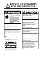
SAFETY INSTRUCTIONS
"DANGER", "WARNING" and "CAUTION" notices appear throughout this manual. It is the
responsibility of the operator and installer of the equipment to read, understand and follow
these notices. If you have any questions regarding these safety instructions, please contact a FURUNO agent or dealer.
DANGER
This notice indicates a potentially
hazardous situation which, if not
avoided, will result in death or
serious injury.
WARNING
This notice indicates a potentially
hazardous situation which, if not
avoided, could result in death or
serious injury.
CAUTION
This notice indicates a potentially
hazardous situation which, if not
avoided, could result in minor or
moderate injury, or property damage.
i
i
SAFETY INFORMATION
FOR THE OPERATOR
WARNING
Do not open the cover of the
equipment.
This equipment uses high
voltage electricity which can
shock, burn or cause death.
Only qualified personnel should work inside the
equipment.
Do not place liquid-filled containers on
the top of the equipment.
Fire or electrical shock can result if a
liquid spills into the equipmtnt.
Do not place heater neat the equipment.
Heat can melt the power cord, which can
result in fire or electrical shock.
Do not dissasemble or modify the
equipment.
Do not operate the unit with wet
hands.
Fire, electrical shock or serious injury
can result.
Electrical shock can result.
Immediately turn off the power at the
ship's mains switchboard if water or
foreign object falls into the equipment
or the equipment is emitting smoke or
fire.
Continued use of the equipment can
cause fire, electrical shock or serious
injury.
WARNING Label attached
WARNING
To avoid electrical shock, do not
remove cover. No user-serviceable
parts inside.
--------------------------------------------------------------------------------------
Name :
Warning Label (1)
Type :
86-003-1011-0
Code No. : 100-236-230
ii
CAUTION
Use the correct fuse.
Use of the wrong fuse can cause fire or
equipment damage.
No single navigation aid (including this
unit) should ever be relied upon as the
exclusive means for navigating your
vessel.
The navigator is responsible for checking
all aids available to confirm his position.
Electronic aids are intended to assist, not
replace, the navigator.
Use of an autopilot with this unit, to
provide automatic steering to
destination, does not eliminate the
need to maintain a watch.
Always maintains a vigilant watch to
prevent collision or grounding.
TABLE OF
CONTENTS
FOREWORD ............................ iii
SYSTEM OVERVIEW ...............1
1. OPERATIONAL OVERVIEW
1.1 Control Description .......................... 1-1
1.2 Turning On and Off the Power ......... 1-2
1.3 Adjusting Display Contrast and
Brilliance .......................................... 1-3
1.4 Selecting the Display Mode .............. 1-3
1.5 Chart Icons ........................................ 1-6
2. TRACK5
2.1 Enlarging/Shrinking the Display ...... 2-1
2.2 Selecting Display Orientation ........... 2-1
2.3 Shifting the Cursor............................ 2-1
2.4 Shifting the Display .......................... 2-2
2.5 Centering Cursor Position................. 2-3
2.6 Centering Own Ship's Position ......... 2-3
2.7 Stopping/Starting Plotting and
Recording of Track ........................... 2-3
2.8 Erasing Track .................................... 2-4
2.9 Selecting Track Plotting Interval ...... 2-4
2.10 Apportioning the Memory .............. 2-5
2.11 Selecting Bearing Reference ........... 2-6
3. MARKS
3.1 Entering/Erasing Marks .................... 3-1
3.2 Selecting Mark Shape ....................... 3-2
3.3 Connecting Marks (selecting mark
connection line) ................................ 3-2
3.4 Entering Event Marks ....................... 3-3
3.5 Selecting Event Mark Shape ............. 3-3
3.6 Entering the MOB Mark ................... 3-4
4. NAVIGATION PLANNING
4.1 Registering Waypoints ...................... 4-1
4.2 Editing Waypoints............................. 4-4
4.3 Deleting Waypoints........................... 4-5
4.4 Registering Routes ............................ 4-5
4.5 Deleting Route Waypoints ................ 4-6
4.6 Replacing Route Waypoints.............. 4-7
4.7 Deleting Routes ................................ 4-7
5. STARTING FOR
DESTINATION
5.1 Setting Destination ........................... 5-1
5.2 Cancelling Destination...................... 5-5
5.3 Erasing Route Waypoints (flags) ...... 5-6
5.4 Finding Range and Bearing Between
Two Points ........................................ 5-7
6. SETTING UP VARIOUS
DISPLAYS
6.1 Selecting Data to Display on the
Data Display ..................................... 6-1
6.2 Selecting Position Format ................. 6-2
6.3 Demo Display ................................... 6-4
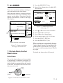
7. ALARMS
7.1 Arrival Alarm, Anchor Watch
Alarm ................................................ 7-1
7.2 Cross Track Error (XTE) Alarm ....... 7-2
7.3 Ship’s Speed Alarm .......................... 7-3
7.4 Trip Alarm......................................... 7-3
7.5 Water Temperature Alarm ................. 7-4
7.6 Depth Alarm ..................................... 7-4
7.7 DGPS Alarm ..................................... 7-4
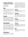
8. MENU SETTINGS
8.1 GPS Menu......................................... 8-1
8.2 Selecting Units of Measurement ....... 8-3
8.3 Mark, Character Size and
Brilliance .......................................... 8-4
8.4 Settings for Connection of
Navigator .......................................... 8-6
iii
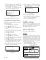
8.5 Receiving Data from Personal
Computer .......................................... 8-8
8.6 DGPS Settings ................................ 8-10
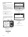
8.7 Displaying GPS Monitor Displays . 8-12
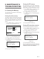
9. MAINTENANCE &
TROUBLESHOOTING
9.1 Clearing the Memory ........................ 9-1
9.2 Preventative Maintenance ................. 9-2
9.3 Error Messages ................................. 9-2
9.4 Troubleshooting ................................ 9-4
9.5 Self Tests ........................................... 9-5
10. INTRODUCTION TO GPS
10.1 What is GPS? ................................ 10-1
10.2 How the GPS Receiver
Calculates Position........................ 10-1
10.3 Position-fixing Accuracy
(HDOP) ......................................... 10-2
APPENDIX
Specifications......................................... A-1
Digital Interface ..................................... A-3
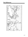
Time Differences ................................. A-17
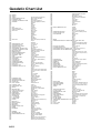
Geodetic Chart List .............................. A-18
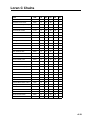
Loran C Chains .................................... A-19
Decca Chains ....................................... A-20
DGPS Reference Station List .............. A-21
Glossary ............................................... A-24
INDEX ............................................. Index-1
Declaration of conformity to type
iv
FOREWORD
A Word to GP-80 Owners
Congratulations on your choice of the
FURUNO GP-80 GPS Navigator. We are confident you will see why the FURUNO name
has become synonymous with quality and reliability.
For over 40 years FURUNO Electric Company has enjoyed an enviable reputation for
innovative and dependable marine electronics equipment. This dedication to excellence
is furthered by our extensive global network
of agents and dealers.
Your navigator is designed and constructed
to meet the rigorous demands of the marine
environment. However, no machine can perform its intended function unless operated and
maintained properly. Please carefully read and
follow the recommended procedures for operation and maintenance.
We would appreciate hearing from you, the
end-user, about whether we are achieving our
purposes.
Thank you for considering and purchasing
FURUNO equipment.
• Man overboard feature records latitude and
longitude coordinates at time of man overboard and provides continuous updates of
range and bearing to that point
• DGPS capability—with built-in DGPS
beacon kit, or accepts DGPS correction
data from external DGPS beacon receiver
• Menu-driven operation
• Bright 122 x 92 mm LCD with temperature compensated tone and brilliance adjustment
• Power consumption is a low 10 W.
• Provision for connection of autopilot (option)—steering data output to autopilot
• Digital display of water temperature and
depth with connection of video sounder
(with NMEA input)
• Memory stores 2,000 points of track and
marks
• "Highway" display provides perspective
view
• Position may be shown in latitude and longitude or LOP (Loran or Decca)
• Four connectors for optional equipment
two IEC 61162-1/NMEA 0183 I/O, one
IEC 61162-1/NMEA 0183 (or log) output
and one DGPS for personal computer) I/O
Program No.
2051011-017 (Apr. 2002)
Features
The GP-80 GPS Navigator is a totally integrated GPS receiver and video plotter consisting of a display unit and an antenna unit.
The high sensitivity receiver tracks up to eight
satellites simultaneously. An 8-state Kalman
filter ensure optimum accuracy in determination of vessel position, course and speed.
In most cases the operator need do no more
than turn on the power to find position.
The main features of the GP-80 are
• Comprehensive navigation data displays
• Storage for 999 waypoints and 30 routes
• Alarms: Arrival, Anchor Watch, Crosstrack Error, Ship's Speed, Water Temperature, Depth, and Trip
v
This page is intentionally left blank.
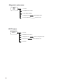
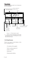
SYSTEM OVERVIEW
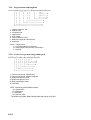
1. Menu Tree
Display selection menu
DISPLAY
SEL
Select Display (Plotter 1, Plotter 2, Highway, Navigation and Data displays)
Main menu
MENU
ESC
1. DISPLAY SETUP
2. TRACK/MARK SETUP
3. ERASE TRACK/MARK
4. ALARM SETTINGS 1/2
ALARM SETTINGS 2/2
5. MANUAL CALCULATION
6.
7. GPS MONITOR
SATELLITE MONITOR
BEACON RCVR MONITOR
STATION MESSAGE
8. SELF TESTS
1. MEMORY, I/O PORT TEST
2. KEYBOARD TEST
3. TEST PATTERN
4. AUTOMATIC TESTING
9. SYSTEM SETTINGS
1. PLOTTER SETUP
2. UNIT SETUP
3. DATA1, 3 OUTPUT SETUP
4. DATA2 OUTPUT SETUP
5. DATA4 I/O SETUP
6. GPS SETUP
DATA4 I/O SETUP 1/2 Out/Com./DGPS
DATA4 I/O SETUP "Out" 2/2
DATA4 I/O SETUP "Com." 2/2
DATA4 I/O SETUP "DGPS" 2/2
GPS SETUP 1/2
GPS SETUP 2/2
7. DGPS SETUP
8. LOP SETUP
9. CLEAR MEMORY
1
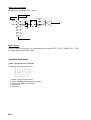
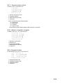
Waypoint, route menu
WPT
RTE
1. Cursor
2. MOB/Event Position
3. Own Ship Position
4. Waypoint List
5. Route Planning
WAYPOINT LIST
ROUTE LIST
GOTO menu
GOTO
1. Cursor
2. MOB/Event Position
3. Waypoint List
4. Route List
5. Cancel
2
GOTO "Waypoint List"
GOTO "Route List"
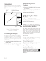
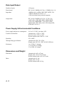
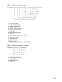
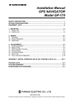
2. System Configuration
ANTENNA
UNIT
Receives GPS
signals.
BEACON ANTENNA UNIT
Receives GPS correction data
from DGPS reference station.
DISPLAY UNIT
Receives and processes
GPS signals to fix
position and display
it in latitude/longitude or LOP.
Ship's Mains
10.2 to 31.2 VDC
3
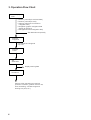
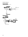
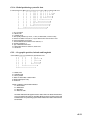
3. Operation Flow Chart
Select display
mode
• Plotter 1 (own ship's track and data)
• Plotter 2 (own ship's track)
• Highway (ship's track overlaid on
navigation lane)
• Navigation (graphic navigation data
display for steering)
• Data (alphanumeric navigation data)
Set destination temporarily
Register
waypoints
• By latitude and longitude
• By LOP
Register
routes
Set
destination
Display steering data
Set alarms
Perform other operations as required.
(Position correction, geodetic chart to use,
enter smoothing, calculate range and
bearing to a point, etc.)
4
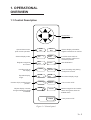
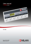
1. OPERATIONAL
OVERVIEW
1.1 Control Description
Cursor keys
Shift display and
cursor.
Opens/closes menu;
quits current operation.
Selects display mode.
Registers waypoints
and routes.
Inscribes mark on
the display.
Expands display
range.
Centers ship's position/cursor
position.
Adjusts display contrast;
changes latitude/longitude
coordinate.
MENU
ESC
NU/CU
ENT
DISPLAY
1
SEL
EVENT
6
MOB
WPT
RTE
GOTO
MARK
ZOOM
IN
2
7
3
PLOT
ON/OFF 8
4
ZOOM
OUT
CENTER
5
TONE
Selects display orientation;
registers selections on menus.
9
CURSOR
ON/OFF 0
CLEAR
POWER
Inscribes event mark at
ship's position; marks man
overboard position
Sets destination.
Turns recording and plotting
of ship's track on/off.
Decreases display range.
Turns cursor on/off.
Deletes waypoints and marks;
clears wrong data; silences
audible alarm.
Turns power on/off.
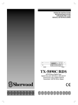
Figure 1-1 Control panel
1–1
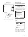
1.2 Turning On and Off the
Power
The GP-80 takes about two minutes to find
position when turned on for the very first time.
Thereafter it takes about 20 seconds to find
position each time the power is turned on.
Turning on the power
Press the [POWER] key.
The unit tests the PROGRAM MEMORY,
SRAM and battery for proper operation and
shows the results on the display. If equipped
with the internal beacon receiver, "BEACON
RCVR INSTALLED" appears at the bottom
of the display. The unit starts up with the last
used display mode.
PROGRAM MEMORY = OK
SRAM
= OK
Internal Battery
= OK
BEACON RCVR INSTALLED*
DATA #3 : LOG PULSE OUTPUT
Several seconds A
later
GPS receiving
condition
34° 23.456´ N 135° 45.678´ E GPS 3D
*: This indication 30is only when beacon reBRG
ceiver is installed.
[01]
Figure 1-2 Appearnace of display when
turning on the power CSE
---°
7°
40
When turning
on the power the50following ocH
RNG
curs:
123 nm
20 seconds after turning on the power, accuSPD
rate position (in latitude
and longitude)
ap20
WGS84
pears
on
the
display.
kt
2nm
12.3
Figure 1-2 Appearnace of display when
turning on the power
1–2
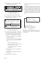
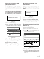
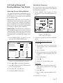
When turning on the power the following occurs:
20 seconds after turning on the power, accurate position (in latitude and longitude) appears on the display.
If position could not be found, "NO FIX" appears at the GPS receiver condition window.
When PDOP value exceeds 6 in the 3D mode
or HDOP value exceeds 4 in the 2D mode,
"DOP" appears to indicate abnormal fixing
and the position indication could not be updated.
When the satellite signal is being received normally, one of the indications shown in Table
1-1 appears depending on equipment setting
and GPS receiver state.
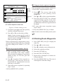
Table 1-1 GPS receiver indication
Equipment
setting
GPS receiver state
indication
2D
GPS 2D (normal)
3D
GPS 3D (normal)
Differential
2D
DGPS 2D (normal)
Differential
3D
DGPS 3D (normal)
Note 1: When PDOP value exceeds 6 in the
3D mode, the position fixing method is
automatically changed to 2D.
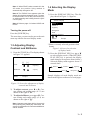
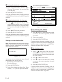
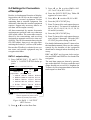
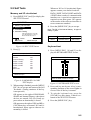
1.4 Selecting the Display
Mode
Note 2: The "DEMO" icon appears when the
display is in the demonstration mode. To return
to normal mode, turn off the power and turn it
on while pressing and holding down the [NU/
CU ENT] key.
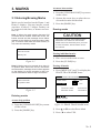
1) Press the [DISPLAY SEL] key. The display shown in Figure 1-4 appears.
Note 3: Refer to page 10-2 about HDOP and
PDOP.
Select Display
Plotter 1
Plotter 2
Turning the power off
Highway
Navigation
Press the [POWER] key.
(DATUM: WGS-84)*
Data
The next time you turn on the power the unit
starts up with the last used display mode.
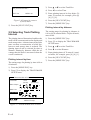
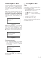
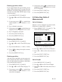
1.3 Adjusting Display
Contrast and Brilliance
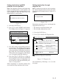
1) Press the [TONE] key. The display shown
in Figure 1-3 appears.
[–]
[+]
Tone:
8 (0~31)
Brilliance:
MENU
:
4 (0~4)
Escape
MENU
:
Select
:
Escape
* Shows currently selected geodetic chart
datum.
Figure 1-4 Screen for selection
of display mode
2) Press the [DISPLAY SEL] key, ▲ or ▼
to select display mode. (When the [DISPLAY SEL] key is pressed, the display
mode changes in sequence shown below.)
Selected display mode appears about 15
seconds later.
Plotter 1
Plotter 2
Data
Highway
Navigation
Sample displays of each display mode are
shown in the figures on the next several pages.
Figure 1-3 Screen for adjustment of display
contrast and brilliance
2) To adjust contrast, press t or s. Current setting and setting range (0–31) are
shown to the right of "s".
3) To adjust brilliance, press ▲ or ▼. Current setting and setting range (0–4) are
shown to the right of "▲".
Note: Operate cursor keys within 10 seconds
after pressing the [TONE] key. Otherwise, the
screen for adjustment of contrast and brilliance
will be cleared.
1–3
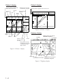
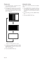
Plotter 1 display
Plotter 2 display
Bearing from own ship
to destination waypoint
Cursor position or lighthouse
data, when cursor is on
Ship's position appears when cursor is off
Course
GPS receiving
Own ship's
bar
condition
track
Own ship
Alarm
mark
range
34° 23.456´ N 135° 45.678´ E DGPS 3D
30
[01]
34° 23.456´ N 135° 45.678´ E DGPS 3D
30
BRG
40
44°
[01]
50
H
CSE
40
50
H
32°
20
BRG TO +
WGS84
2.00 nm
123°
RNG TO +
20
11.5
WGS84
2.00 nm
Figure 1-6 Plotter 2 display
nm
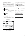
Highway display
Horizontal
range
Course
Grid
width
Course
Cursor
Position
Speed, or range
from own ship
to cursor
Course
Bearing from own ship to
detination waypoint
Course
Range from own ship
to destination waypoint,
or bearing from own
ship to cursor
Figure 1-5 Plotter 1 display
WGS84
North mak
Own ship mark
Cross track error scale
Range from own ship to
destination waypoint
Figure 1-7 Highway display
1–4
Speed
2) With autopilot connection, automatic
mode
Navigation display
1) No autopilot connection
Cross track
error meter
Bearing from own
ship to destination
waypoint
Bearing
scale
Destination
waypoint no.
12.3 kt
Speed
N
12.3 kt
63°
CSE
123°
0.1nm
ETA
TTG
Estimated Time of
Arrival (15th23:45)
Cross track
error scale
Auto Pilot
10.3 kt
S
Auto
0.1nm
123 nm
RNG
0.1nm
123 nm
TRIP
Str
123° P 23° 789 nm
Auto mode
Heading
Rudder angle
TRIP
789 nm
Figure 1-9 Navigation display, with
autopilot connection, automatic mode
Trip
distance
Time To Go
(3days17hrs45min)
Cross track
error indication
Hdg
S
RNG
3D
17H 45M
15
23:45'
0.1nm
VTD
BRG
10.3 kt
63°
CSE:
123°
SPD
N
VTD
BRG:
DGPS 3D
E
SPD
E
Velocity To
Destination
TO; 012
DGPS 3D
TO; 012
Range from own
ship to destination
waypoint
Figure 1-9 Navigation display,
no autopilot connection
3) Autopilot connection, modes other than
automatic mode (manual, nav, etc.)
TO; -
DGPS 3D
--
E
SPD
12.3 kt
N
VTD
BRG:
10.3 kt
63°
CSE:
123°
0.1nm
Auto Pilot
Man
Man: Manual mode
Nav: Nav mode
Other:---
Hdg
S
AP CSE
0.1nm
Str
123°
TRIP
123° P 23° 789 nm
Heading
Rudder angle
Autopilot-set
course
Figure 1-10 Navigation display, with
autopilot connection, modes other than
the automatic mode
1–5
Data display
(Window assignment and size of characters
are user-definable)
Position in latitude and
longitude or LOPs
Fixing date and time*
Cursor
DGPS 3D
SEP 12, 1995 23:59'59" U
POSITION
WGS84
12° 23.456' N
123° 23.456' E
RNG
TO : 001
BRG
31.23
nm
SPD
NEXT
CSE
12.3
kt
User-defined
display data #1
MARINE
POINT1
223.4°
123.4°
User-defined
display data #4
User-defined
display data #2
: 002
MARINE
POINT2
Current destination waypoint
Next destination waypoint
User-defined
display data #3
User-defined
display window
Figure 1-11 Data display mode
*: "- -" appears until calculating position after
turning on the power. If fixing error occurs
this indication stops.
1.5 Chart Icons
Various icons appear on the display to alert
you to equipment status.
: L/L position offset applied.
: Track recording tunned off.
: Alarm is violated.
: North mark.
: Demonstration display.
1–6
2. TRACK
2.3 Shifting the Cursor
The cursor can be shifted with the cursor keys.
2.1 Enlarging/Shrinking the
Display
You may enlarge and shrink the display on
the Plotter 1 and Plotter 2 displays, with the
[ZOOM IN] and [ZOOM OUT] keys. The
horizontal range is available among 0.25, 0.5,
1, 2, 4, 8, 16, 32, 64, 128 and 192 nautical
miles for plotter 1 and 0.36, 0.71, 1.42, 2.84,
5.69, 11.38, 22.76, 45.51, 91.02, 182.04,
273.07 nautical miles for plotter 2 display.
The [ZOOM IN] key enlarges the display and
the [ZOOM OUT] key shrinks it. Each time a
zoom key is pressed the display range appears
at the center of the display for about three seconds.
2.2 Selecting Display
Orientation
Display orientation can be selected on the
Plotter 1, Plotter 2 and Highway displays, with
the [NU/CU ENT] key. Two display orientations are available: north-up and course-up.
1) Press the [CURSOR ON/OFF] key to turn
on the cursor.
2) Press the cursor keys.
The cursor moves in the direction of the cursor key pressed. When the cursor reaches the
edge of the display, the display shifts in the
direction opposite.
Data and cursor state
Cursor state determines what data are shown
on the display.
Cursor turned on, cursor data
Cursor position is displayed in latitude and
longitude or LOPs (depending on menu setting) at the top of the display. The range and
bearing from own ship to the cursor appear at
the right hand side of the display, when in the
Plotter 1 display.
Cursor turned off
Cursor mark
Cursor position in
latitude and longitude
North-up display
In the north-up display, true north (0 ) is at
the top of the display. Own ship moves on the
display in accordance with true speed and true
motion. Land is stationary.
34° 23.456´ N 135° 45.678´ E DGPS 3D
BRG
234°
CSE
345°
Course-up display
BRG To +
123°
Destination set
RNG To +
The destination is at the top of the display and
the north mark ( ) appears at the left side of
the display.
Destination not set
Ship's heading or course is at the top of the
display. The north mark appears at the left side
of the display.
11.5nm
WGS84
2.0 nm
Cursor
Range from own
ship to cursor
Bearing from own
ship to cursor
Figure 2-1 Data displayed when
the cursor in on
2–1
Cursor turned off
Ship's position (in latitude and longitude or
LOPs), speed and course appear on the display.
Own ship
mark
2.5 Centering Cursor
Position
1) Press the [CURSOR ON/OFF] key to turn
on the cursor.
2) Press the cursor keys to position the cursor.
Own ship position
in latitude and longitude
3) Press the [CENTER] key.
34° 23.456´ N 135° 45.678´ E
DGPS 3D
BRG
234°
CSE
345°
RNG
123
nm
2.6 Centering Own Ship's
Position
1) Press the [CURSOR ON/OFF] key to turn
off the cursor.
2) Press the [CENTER] key.
SPD
12.3 kt
Course
Speed
Figure 2-2 Data displayed when
the cursor is turned off
2.4 Shifting the Display
The display can be shifted on the Plotter 1
and Plotter 2 displays, with the [CURSOR
ON/OFF] key. When own ship tracks off the
display it is automatically returned to the
screen center.
1) Press the [CURSOR ON/OFF] key to turn
off the cursor.
2) Press the cursor keys. The display shifts
in the direction of the cursor key pressed.
2.7 Stopping/Starting Plotting
and Recording of Track
The GP-80 stores 2,000 points of track and
marks. When the memory becomes full the
oldest track is erased to make room for the
latest. Thus you may want to conserve the
memory when, for example, you are returning to port or are anchored.
Procedure
Press the [PLOT ON/OFF] key to start/stop
recording and plotting of track.
When plotting is resumed
"Resuming track plot" appears at the center
of the display for about three seconds.
When plotting is stopped
"Stopping track plot" appears at the center of
the display for about three seconds and " H "
appears at the left side of the display. (" H "
does not appear on the Navigation and Data
displays.)
2–2
2.8 Erasing Track
Hold icon
(appears while recording
of track is stopped)
34° 23.456´ N 135° 45.678´ E
The track stored in the memory and displayed
on the screen can be erased.
DGPS 3D
BRG
234°
CSE
345°
H
RNG
123
nm
SPD
12.3 kt
This portion of track
does not appear on
the display
Own ship
Recording of
track started
Ship’s track
while recording is
stopped
Recording of track
turned off
Figure 2-3 Track not plotted or recorded
when plotting is stopped
CAUTION
Track cannot be restored once erased. Be
absolutely sure you want to erase all track.
1) Press the [MENU ESC] key. The MAIN
MENU appears.
MAIN MENU
1. DISPLAY SETUP
2. TRACK/MARK SETUP
3. ERASE TRACK/MARK
4. ALARM SETTINGS
5. MANUAL CALCULATION
6.
7. GPS MONITOR
8. SELF TESTS
9. SYSTEM SETTINGS
ENT: Enter
MENU: Escape
Figure 2-4 MAIN MENU
2) Press [3] to select ERASE TRACK/
MARK.
ERASE TRACK/MARK
Erase Track
No
Yes
Erase Mark
No
Yes
Track Pts. Used:
345/1000 Pt
Mark Pts. Used:
123/1000 Pt
: Select
MENU: Escape
Figure 2-5 ERASE TRACK/MARK menu
3) Press ▲ or ▼ to select Erase Track.
4) Press s to select Yes. The message shown
in Figure 2-6 appears.
2–3
3) Press ▲ or ▼ to select Track Rec.
Are you sure to erase ?
ENT: Yes
4) Press t to select Time.
MENU: No
Figure 2-6 Prompt for erasure
of track, mark
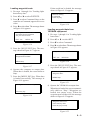
5) Enter plotting interval in four digits. To
enter 30 seconds, for example, press [0]
[0] [3] [0].
6) Press the [NU/CU ENT] key.
7) Press the [MENU ESC] key.
5) Press the [NU/CU ENT] key.
Plotting interval by distance
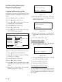
2.9 Selecting Track Plotting
Interval
The setting range for plotting by distance is
0.01 to 99.99 nautical miles. To plot all track,
enter 00.00.
The plotting interval determines both how the
track will be reconstructed on the display and
track storage time. A shorter interval provides
more accurate reconstruction of track line,
however total storage time is reduced. The
plotting interval can be selected by time or
distance. Plotting by distance offers the advantage that the track is not stored when the
vessel is anchored.
1) Press the [MENU ESC] key.
2) Press [2] to display the TRACK/MARK
SETUP menu.
3) Press ▲ or ▼ to select Track Rec.
4) Press s to select Distance.
5) Enter plotting interval. To enter 0.1 nautical miles, for example, press [0] [0] [1].
6) Press the [NU/CU ENT] key.
Plotting interval by time
7) Press the [MENU ESC] key.
The setting range for plotting by time is 00 to
60 minutes.
1) Press the [MENU ESC] key.
2) Press [2] to display the TRACK/MARK
SETUP menu.
TRACK/MARK SETUP
Track Rec
Time
(01'00)
Dist
(00.50nm)
Mark Shape
Mark Line
Event Mark
: Select
ENT: Enter
MENU: Escape
Figure 2-7 TRACK/MARK SETUP menu
2–4
2.10 Apportioning the
Memory
The memory holds 2,000 points of track and
marks and may be apportioned as you like.
The default memory setting stores 1,000
points each of track and marks.
CAUTION
All data are erased whenever the memory
apportion setting is changed, even when the
previous value is re-entered.
3) Press [1] to display the PLOTTER SETUP
menu.
PLOTTER SETUP
Memory Apportion
Trk = 1000 / 2000Pt
Bearing Ref.
True
Mag Variation
Auto
(07° W)
Calculation
R.L
User defined #1
RNG
User defined #2
SPD
User defined #3
BRG
User defined #4
CSE
ENT: Enter
Mag
Man
(00° E)
G.C
MENU: Escape
To store 1,500 points of track and 500 marks,
for example, do the following:
1) Press the [MENU ESC] key.
2) Press [9] to display the SYSTEM SETTINGS menu.
SYSTEM SETTINGS
1. PLOTTER SETUP
2.
2. UNIT
UNIT SETUP
SETUP
3. DATA 1, 3 OUTPUT SETUP
4. DATA 2 OUTPUT SETUP
5. DATA 4 I/O SETUP
6. GPS SETUP
7. DGPS SETUP
8. LOP SETUP
9. CLEAR MEMORY
Figure 2-9 PLOTTER SETUP menu
4) Press ▲ or ▼ to select Memory Apportion.
5) Enter amount of track to store, in four digits. To store 1,500 track points, for example, press [1] [5] [0] [0].
6) Press the [NU/CU ENT] key, or ▲ or ▼.
You are asked if it is all right to erase all
data.
Setting erases all data!
Are you sure to change ?
ENT: Yes
ENT: Enter
MENU: No
MENU: Escape
Figure 2-10
Figure 2-8 SYSTEM SETTNGS menu
7) Press the [NU/CU ENT] key.
8) Press the [MENU ESC] key.
2–5
2.11 Selecting Bearing
Reference
Ship's course and bearing to waypoint may
be displayed in true or magnetic bearing.
Magnetic bearing is true bearing plus (or minus) earth's magnetic deviation.
Displaying true or magnetic bearing
The default setting displays magnetic bearings.
1) Press the [MENU ESC] key.
2) Press [9] to display the SYSTEM SETTINGS menu.
3) Press [1] to display the PLOTTER SETUP
menu.
4) Press ▲ or ▼ to select Bearing Ref.
5) Press t or s to select True or Mag.
6) Press the [NU/CU ENT] key, ▲ or ▼.
7) Press the [MENU ESC] key.
Entering magnetic variation
The location of the magnetic north pole is different from the geographical north pole. This
causes a difference between the true and magnetic north direction. This difference is called
magnetic variation, and varies with respect to
the observation point on the earth. Magnetic
variation may be entered automatically or
manually.
1) Press the [MENU ESC] key.
2) Press [9] to display the SYSTEM SETTINGS menu.
3) Press [1] to display the PLOTTER SETUP
menu.
4) Press ▲ or ▼ to select Mag Variation.
5) Press t or s to select Auto or Man. For
automatic, current variation appears in parentheses.
6) For manual entry, enter variation in two
digits, referring to a nautical chart. If the
variation is 10°, for example, press [1] [0].
7) If necessary, press the [ ] key to change
coordinate from east to west or vice versa.
8) Press the [NU/CU ENT] key.
9) Press the [MENU ESC] key.
2–6
3. MARKS
At cursor intersection
1) Press the [CURSOR ON/OFF] key to turn
on the cursor.
3.1 Entering/Erasing Marks
Marks can be inscribed on the Plotter 1 and
Plotter 2 displays. You may inscribe a mark
anywhere, in one of 13 shapes. Further, can
be connected with lines, to denote net location, etc.
Note 1: When the mark memory becomes full
no marks can be entered. When this occurs, the
buzzer sounds and the message shown below
appears on the display for three seconds to alert
you. To enter a mark when the mark memory is
full, erase unnecessary marks.
Can't save mark
Memory full
2) Operate the cursor keys to place the cursor on the location for the mark.
3) Press the [MARK] key.
Erasing marks
CAUTION
All marks, including event marks and the
MOB mark, are erased on the ERASE
MARK menu. Be absolutely sure you want
to erase all marks; erased marks cannot
be restored.
Erasing individual marks
1) Place cursor on the mark to erase.
Figure 3-1
Note 2: Marks cannot be entered when there is
no position data. When this occurs, the buzzer
sounds and the message shown below appears
on the display for thre3e seconds to alert you.
Check the antenna cable for tight connection.
2) Press the [CLEAR] key.
Erasing all marks
1) Press [MENU ESC] and [3] to display the
ERASE TRACK/MARK menu.
ERASE TRACK/MARK
Can't save mark
No position data
Figure 3-2
Entering marks
Erase Track
No
Yes
Erase Mark
No
Yes
Track Pts. Used:
345/1000 Pt
Mark Pts. Used:
123/1000 Pt
: Select
MENU: Escape
At own ship position
1) Press the [CURSOR ON/OFF] key to turn
off the cursor.
2) Press the [MARK] key.
Figure 3-3 ERASE TRACK/MARK menu
2) Press ▲ or ▼ to select Erase Mark.
3) Press s to select YES.
3–1
Are you sure to erase ?
ENT: Yes
MENU: No
3.3 Connecting Marks
(selecting mark connection
line)
4) Press the [NU/CU ENT] key.
Marks can be connected with lines to denote
net location, fishing spot, etc. Three types of
connection lines are available and the "•" setting disables connection of lines.
5) Press the [MENU ESC] key.
1) Press [MENU ESC] and [2]
Figure 3-4
2) Press ▲ or ▼ to select Mark Line.
3.2 Selecting Mark Shape
3) Press t or s to select mark line desired.
13 mark shapes are available. Select mark
shape as follows:
4) Press the [NU/CU ENT] key.
1) Press [MENU ESC] and [2] to display the
TRACK/MARK SETUP menu.
TRACK/MARK SETUP
Track Rec
Time
(01'00)
Dist
(00.50nm)
Mark Shape
Mark Line
Event Mark
: Select
ENT: Enter
MENU: Escape
Figure 3-5 TRACK/MARK SETUP menu
2) Press ▲ or ▼ to select Mark Shape.
3) Press t or s to select mark shape desired.
4) Press the [NU/CU ENT] key.
5) Press the [MENU ESC] key.
The next mark entered will be inscribed in
the shape selected here.
3–2
5) Press the [MENU ESC] key.
3.4 Entering Event Marks
Event marks can denote any important present
position; for example, a good fishing spot.
Event marks can be saved as ordinary marks
and the unit automatically numbers them from
01 to 99.
Note 1: When the mark memory becomes full
no event marks can be entered. When this occurs, the buzzer sounds and the message shown
below appears on the display for three seconds
to alert you. To enter an event mark when the
mark memory is full, erase unnecessary event
marks.
3.5 Selecting Event Mark
Shape
Event marks are available in 10 shapes. Select
event mark shape as follows.
1) Press [MENU ESC] and [2] to display the
TRACK/MARK SETUP menu.
2) Press ▲ or ▼ to select Event Mark.
3) Press t or s to select event mark shape
desired.
4) Press the [NU/CU ENT] key.
5) Press the [MENU ESC] key.
Can't save event
Memory full
The next event mark entered will be inscribed
in the shape selected here.
Figure 3-6
Note 2: Event Marks cannot be entered when
there is no position data. When this occurs, the
buzzer sounds and the message shown below
appears on the display for three seconds to alert
you. Check the antenna cable for tight connection.
Can't save event/MOB
No position data
Figure 3-7
Entering event marks
1) Press the [EVENT MOB] key less than
three seconds. The position at the exact
moment the key is pressed is saved as an
event position.
Saved event position
34°40.123’ N
135°21.123’ E
Figure 3-8
To erase event marks, see "3.1 Entering/
Erasing Marks".
3–3
3.6 Entering the MOB Mark
2) Press the [NU/CU ENT] key. If the display in use is Highway, Navigation or
Data, they are automatically replaced by
the Plotter 2 display.
The MOB mark denotes man overboard position. To mark man overboard position, press
the [EVENT MOB] key. When the key is
pressed, the position at the exact moment the
key is pressed automatically becomes the destination. Further, the Plotter 1 display replaces
the display in use when it is other than a plotter display.
Note: You may cancel MOB position as destination by pressing the [MENU ESC] key instead of
the [NU/CU ENT] key at step 2. Note that the
MOB mark remains on the display.
Only one MOB mark may be entered, and
each time the MOB mark is entered the previous MOB mark and its position data are
written over.
See "3.1 Entering/Erasing Marks". (MOB
marks cannot be erased with the cursor.)
Note: The MOB mark cannot be entered when
there is no position data. When this occurs, the
buzzer sounds and the message shown below
appears on the display for three seconds to alert
you. Check the antenna cable for tight connection.
Can't save event/MOB
No position data
Figure 3-9
1) Press the [EVENT MOB] key for at least
three seconds.
The MOB mark ("M") is entered at the
MOB position and the message shown in
Figure 3-10 appears.
Saved MOB position
Are you sure to change course
to MOB position ?
ENT: Yes
MENU: No
Figure 3-10
3–4
Erasing MOB mark
4. NAVIGATION
PLANNING
4.1 Registering Waypoints
In navigation terminology a waypoint is a
particular location on a voyage whether it be
a starting, intermediate or destination
waypoint.
The GP-80 can store 999 waypoints, numbered from 001–999. Waypoints can be registered four ways:
• by cursor
• by MOB position or event position
• at own ship's position, and
• through the waypoint list.
Registering waypoints by the
cursor
1) Press the [WPT RTE] key. The Waypoint/
Route menu appears.
Waypoint/Route
1. Cursor
2. MOB/Event Position
3. Own ship Position
4. Waypoint List
5. Route Planning
: Cursor
ENT: Enter
The display changes to Plotter 2 when the
Highway, Navigation or Data mode is in
use.
3) Press the cursor keys to place the cursor
on the location desired for the waypoint.
4) Press the [NU/CU ENT] key.
A window similar to the one shown in Figure 4-3 appears. The waypoint's position
and date and time registered appear on the
first and second lines. Waypoints are automatically given the youngest empty
waypoint number and this number appears
on the third line. You may, however, assign a different number. If the waypoint
shares the same position with a mark, the
mark's position and date and time entered
are registered as waypoint data.
If the waypoint memory is full, the
waypoint number line in the window is
blank. In this case waypoints cannot be
entered unless a waypoint is written over
or deleted.
To assign waypoint number, go to step 5.
If you do not want to change the waypoint
number, go to step 6 to select mark shape
and enter comment.
30° 12.345' N 135° 23.456' W
AUG 12’ 95 12 : 34U
No. : 1
123
Mark :
Cmnt :
: Cursor
MENU: Escape
ENT: Enter
: Column
MENU: Escape
Figure 4-1 Waypoint/Route menu
Figure 4-3
2) Press [1] to select Cursor. The following
display appears.
5) Enter waypoint number, in three digits
(001–999).
Place cursor on desired location
ENT: Enter
MENU: Escape
Figure 4-2
4–1
6) Press ▼ to select waypoint mark shape.
The following display appears.
: Cursor
ENT: Enter
MENU: Escape
Figure 4-4 Screen for selecting
waypoint mark shape
Control is returned to the last used display mode.
When the waypoint number entered at step
5 already exists, the message shown in
Figure 4-4 appears if the waypoint is part
of the current destination or route or is part
of a route. If it is alright to write over the
waypoint and its data, press the [Y] key.
To change waypoint number, press the [N]
key.
7) Press t or s to select mark shape.
8) Press the [NU/CU ENT] key. The display
shown in Figure 4-5 appears.
1st line
Are you sure to change ?
A
ABCDE FGHIJ KLMNO PQRST UVWXYZ
abcde
fghij
klmno
pqrst
uvwxyz
ENT: Yes
MENU: No
1234567890 _#%’()+-./:;<=>?
ENTER
COMMENT: _
: Cursor
ENT: Set
___________
MENU: Escape
Figure 4-5 Screen for entry of
comment for waypoint
9) You may enter a comment, as shown in
the procedure which follows, or skip to
step 10 to finish. The comment may consist of up to 12 alphanumeric characters.
1 Press the cursor keys to select alphanumeric character.
2 Press the [NU/CU ENT] key. Selected
character appears on the COMMENT
line.
• To create a space, select "_".
• Numeric data can be input directly
by pressing numeric keys.
• To clear wrong data, press the
[CLEAR] key.
3 Repeat steps 1 and 2 to complete the
comment.
4 Select ENTER and press the [NU/CU
ENT] key.
10) Press the [NU/CU ENT] key.
4–2
This wpt is GOTO
This wpt is in registered route
This wpt is in selected route
Figure 4-6
Note: If you fail to enter waypoint number, "Enter waypoint number" appears on the display for
three seconds.
Registering waypoints by MOB
position/event position
Registering waypoints by own
ship's position
The MOB position or an event position can
be registered as a waypoint. Event marks are
numbered from 01 to 99; 01 is the latest event
mark.
Note: When there is no position data, you cannot register a waypoint at own ship's position.
The buzzer sounds and the following message
appears.
Note: You cannot register a MOB position or
event position when there are no MOB positions
or event positions saved. The buzzer sounds and
the message shown in Figure 4-7 appears for
three seconds to alert you.
No position data
Figure 4-9
No MOB/event data in memory
1) Press the [WPT/RTE] key.
2) Press [3] to select Own Ship Position.
Figure 4-7
3) Follow steps 5 through 11 in "Registering
waypoints by the cursor" on page 4-1.
1) Press the [WPT/RTE] key.
2) Press [2] to select MOB/Event Position.
The display shown in Figure 4-8 appears.
Registering waypoints through the
waypoint list
1) Press the [WPT/RTE] key.
[MOB] Displaying MOB data
34° 12.345' N 130° 23.456' E
AUG 12' 94 19 : 25U
[#01] Displaying event data
:Recall
34° 12.345'
N 130° 23.456' E
ENT:Enter
AUG
12' 95 19 : 25U
MENU:Escape
: Paging
ENT: Enter
MENU: Escape
2) Press [4] to display the waypoint list.
3) Press [ ] to select position format; latitude and longitude or LOP.
WAYPOINT LIST (L/L)
001 34° 12.345' N 130° 23.456' W
MARINE POINT AUG 12' 95 12 : 35U
Figure 4-8
3) Press t or s to display the MOB position or event position to register as a
waypoint.
4) Press the [NU/CU ENT] key.
5) Follow steps 5 through 11 in "Registering
waypoints by the cursor" on page 4-1.
002
36° 12.345' N 135° 23.456' W
AUG 13' 95 13 : 45U
A POINT
003
°
.
'N
°
.
'W
004
°
.
'N
°
.
'W
: L/L´LOP
ENT: Enter
: Edit
MENU: Escape
Figure 4-10
4) Press ▲ or ▼ to select waypoint number.
5) Press t or s to enter position. The display should now look something like Figure 4-11.
4–3
4.2 Editing Waypoints
Edit = Waypoint : 001
_ _° _ _._ _ _' N _ _ _°_ _._ _ _' W
1) Press [WPT RTE] and [4].
Mark : __
Cmnt :
2) Press ▲ or ▼ to select waypoint to edit.
3) Press s.
: Cursor
ENT: Enter
: Column
MENU: Escape
4) Edit the contents of the waypoint.
Figure 4-11
6) Enter latitude and longitude. To enter
34°12.345' N 135°23.456' E, for example,
press;
([
]) [3] [4] [1] [2] [3] [4] [5]
([
]) [1] [3] [5] [2] [3] [4] [5] [6]
5) Press the [NU/CU ENT] key. The message shown in Figure 4-12 appears if the
waypoint is currently selected as destination, is part of a route, or is in the route
currently selected as destination.
1st line
Are you sure to erase ?
ENT: Yes
To change N to S or E to W, press [
MENU: No
].
7) Press ▼.
8) Press t or s to select mark.
9) Press the [NU/CU ENT] key.
10) Enter comment.
11) Press the [NU/CU ENT] key twice.
The waypoint list reappears. Waypoint
position and date and time the waypoint
was entered appear on the list.
12) To enter another waypoint through the
waypoint list, return to step 4.
13) Press the [MENU ESC] key to finish.
4–4
This wpt is GOTO
This wpt is in registered route
This wpt is in selected route
Figure 4-12
6) Press the [NU/CU ENT] key.
The waypoint and its data are deleted.
Enter new data, referring to "4.1 Registering Waypoints".
7) Press the [MENU ESC] key.
4.3 Deleting Waypoints
4.4 Registering Routes
Deleting waypoints by the cursor
Often a trip from one place to another involves
several course changes, requiring a series of
route points which you navigate to, one after
another. The sequence of waypoints leading
to the ultimate destination is called a route.
The GP-80 can automatically advance to the
next waypoint on a route, so you do not have
to change the destination waypoint repeatedly.
1) Place the cursor on the waypoint to delete.
2) Press the [CLEAR] key.
Deleting waypoints through the
waypoint list
1) Press [WPT RTE] and [4].
2) Press ▲ or ▼ to select waypoint to delete.
3) Press the [CLEAR] key. The message
shown in Figure 4-13 appears if the
waypoint is currently selected as destination, is part of a route, or is in the route
currently selected as destination.
1st line
Are you sure to erase ?
ENT: Yes
MENU: No
This wpt is GOTO
This wpt is in registered route
This wpt is in selected route
Figure 4-13
Note: All waypoint marks (as well as all other
marks) and their data can be cleared
collectively by clearing the Plotter memory.
For further details, see page 9-1.
4) Press the [NU/CU ENT] key.
Note: To cancel erasure, press the [MENU
ESC] key instead of the [NU/CU ENT] key.
The waypoint list appears.
5) Press the [MENU ESC] key.
The GP-80 can store 30 routes and each route
may contain up to 30 waypoints. Routes can
be registered while in the Plotter 1 or Plotter
2 display mode.
Registering routes
1) Press the [WPT/RTE] key.
2) Press [5] to select Route Planning. The
route list appears.
ROUTE LIST
No. PTS Total Dist.
TTG
Remarks
01 30 1234 . 56 nm 12D15H28M UseFwd
02 25
234 . 56 nm 2D08H35M
03 30 *999. 99 nm *9D*9H*9M
.
nm
04
D H M
05 30 6543 . 21 nm 34D23H45M
.
nm
06
D H M
: Route No.
ENT: Enter
: Edit
MENU: Escape
Remarks
Use: In use
Fwd: Traverse waypoints in forward order
Rvs: Traverse waypoints in reverse order
Figure 4-14 Route list
3) Press ▲ or ▼ to select route number.
4) Press s.
The route planning/waypoint list window
appear as shown in Figure 4-15. The
waypoint list window lists the position and
data for each registered waypoint. No position or data appears for empty
waypoints.
4–5
2 Using previously registered waypoints
ROUTE : 01 (In Use , REVERSE)
skip Distance TTG
Trial Speed : Auto
01
EN
EN
02
001
Man (012.0kt)
. nm D M
. nm D M
H
H
Route
editing
screen
34° 12.345' N 130° 23.456' E
MARINE POINT AUG 12' 95 12 : 35U
002 36° 12.345' N 135° 23.456' E
AUG 13' 95 13 : 45U
A POINT
: RTE
WPT CLEAR: Delete
ENT: Enter MENU: Escape
Waypoint
list
Use: In use
Fwd: Traverse waypoints in forward order
Rvs: Traverse waypoints in reverse order
Figure 4-15 Route editing screen
5) If required, press ▲ to enter the speed by
which to calculate time-to-go.
6) Press t or s to select Auto or Man.
Auto: Current average speed is used to
calculate the time-to-go. Manual: Entered
speed is used to calculate the time-to-go.
Enter speed and press ▼.
Route waypoints may be registered two ways:
entering waypoint nubmer directly or through
the route editing screen. Follow 1 or 2 below.
Enter waypoints in the order they will be traversed; not by waypoint number order.
7) Press [ ]. The reverse video on the
waypoint on route planing screen
disapperars.
8) Press ▲ or ▼ to select waypoint number.
9) Press the [NU/CU ENT] key. Selected
waypoint number appears on the route
editing screen. The distance and time-togo indications to the first waypoint entered
are blank.
10) To enter other route waypoints, repeat
steps 8 and 9.
11) Press the [MENU ESC] key to finish.
Note: To return to the route editing screen, press
[
].
4.5 Deleting Route Waypoints
1) Press [WPT RTE] and [5] to display the
route list.
2) Press ▲ or ▼ to select route.
3) Press s to display route editing screen.
1 Entering waypoint number directly
4) Select the waypoint to delete.
7) Enter waypoint number, in three digits.
The cursor shifts to the "Skip" window.
The procedure for skipping a waypoint is
shown on page 5-4. For now, go to the
next step.
5) Press the [CLEAR] key.
8) Press ▼ to continue. If the waypoint entered in step 7 does not exist, you are informed that the waypoint does not exist
and entry is cancelled.
8) Press the [MENU ESC] key. The route is
rearranged to reflect the change.
9) Enter other route waypoints by repeating
steps 7 and 8.
10) Press [MENU ESC] to finish.
4–6
6) Press the [NU/CU ENT] key.
7) Repeat steps 4 through 6 to continue deleting waypoints.
4.6 Replacing Route
Waypoints
1) Press [WPT RTE] and [5] to display the
route list.
2) Press ▲ or ▼ to select route.
3) Press s to display route editing screen.
4.7 Deleting Routes
1) Press [WPT RTE] and [5] to display the
route list.
2) Press ▲ or ▼ to select route to delete.
3) Press the [CLEAR] key. The display
shown in Figure 4-17 appears if the route
is in use.
4) On the route editing screen, place the cursor on waypoint number to replace.
5) Enter new waypoint number.
1st line
Are you sure to erase ?
6) Press the [NU/CU ENT] key. The message shown in Figure 4-16 appears.
ENT: Yes
This waypoint already exists
Are you sure to change ?
ENT: Yes
MENU: No
MENU: No
This route is in use
Figure 4-17
4) Press the [NU/CU ENT] key.
Figure 4-16
5) Press the [MENU ESC] key.
7) Press the [NU/CU ENT] key.
8) Press the [MENU ESC] key twice.
4–7
This page is intentionally left blank.
5. STARTING FOR
DESTINATION
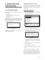
5.1 Setting Destination
There are four ways by which you can set
destination:
• By cursor
• By MOB position or event position
• By waypoint, and
• By route.
Note 1: Destination cannot be set when there is
no GPS position data. When there is no position
data, the buzzer sounds and the message shown
in Figure 5-1 appears.
Setting destination by cursor
Using the cursor you may set a destination
consisting of 30 points. When all 30 points
are entered, the GP-80 automatically disables
further entry.
Setting single destination
1) Press the [GOTO] key. The menu shown
in Figure 5-2 appears.
GOTO Setting
1. Cursor
2. MOB/Event Position
3. Waypoint List
4. Route List
5. Cancel
: Cursor
No position data
ENT
: Enter
MENU : Escape
Figure 5-2 GOTO setting menu
Figure 5-1
Note 2: Previous destination is cancelled whenever a destination is set.
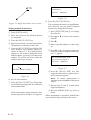
2) Press [1] to select Cursor. The display
shown in Figure 5-3 appears.
Place cursor on desired location
Press ENT twice to finish
ENT:Enter CLR:Clear MENU:Escape
Figure 5-3
If the display in use is other than Plotter
1, the Plotter 2 display is automatically
selected.
3) Place the cursor on the location desired
for destination.
4) Press the [NU/CU ENT] key.
Note: To clear selection, press the [CLEAR]
key.
5) Press the [NU/CU ENT] key to finish.
Control is returned to the display mode in use
before you set destination. A dashed line connects own ship and the destination, which is
marked with a flag, as shown in Figure 5-4.
5–1
Flag
mark
Overwriting ?
ENT:Yes MENU:No
Figure 5-6
8) Press the [NU/CU ENT] key.
Figure 5-4 Single destination set by cursor
Setting multiple destinations
1) Press [GOTO] and [1].
2) Place the cursor on the location desired
for waypoint.
3) Press the [NU/CU ENT] key.
4) Repeat steps 2 and 3 to enter other points.
Waypoints are connected with a line.
5) Press the [NU/CU ENT] key to finish. The
route number entry display appears as
shown in Figure 5-5. If no route number
appears or you want to change the route
number shown, go to step 6 to enter route
number. To register the route under the
number shown, go to step 8.
The waypoints do not have waypoint numbers, however you can attach waypoint
numbers by doing the following.
1 Press [WPT RTE] and [5] to display
the route list.
2 Press ▲ or ▼ to select route number
entered.
3 Press s.
4 Enter waypoint number, in three digits.
5 Press ▼. If the waypoint number already exists the message shown in Figure 5-7 appears.
This waypoint already exists
Are you sure to change ?
ENT:Yes MENU:No
Enter route number
01
ENT:Enter MENU: Escape
Figure 5-5
6) Key in route number.
7) Press the [NU/CU ENT] key. Waypoints
are marked with flags and are connected
with a dashed line.
If the route number entered already exists
the message shown in Figure 5-6 appears.
5–2
Figure 5-7
6 Press the [NU/CU ENT] key. The
waypoint entered here replaces previously entered waypoint.
Note: To cancel replacement of
waypoint, press the [MENU ESC] key at
step 6.
7 Repeat steps 4 and 5 to enter other
waypoint numbers.
8 Press the [MENU ESC] key twice to
finish.
When destination is cancelled, dashed lines
are erased but flags remain on the screen.
Setting destination by MOB
position or event position
Setting destination through
waypoint list
Note: This operation cannot be performed when
there is no MOB position or event position. The
buzzer sounds and the message shown in Figure 5-8 appears to alert you when there is no
MOB position or event position.
Note: A waypoint must exist to set it as destination. When a waypoint does not exist, the buzzer
sounds and the message shown in Figure 5-10
appears.
No waypoint data
No MOB/event data in memory
Figure 5-10
Figure 5-8
1) Press the [GOTO] key.
Destination waypoint can be set through the
waypoint list two ways:
2) Press [2] to select MOB/Event Position.
The display shown in Figure 5-9 appears.
• By entering waypoint number, and
• By selecting waypoint by cursor
[MOB] Displaying MOB data
34° 12.345' N 130° 23.456' E
AUG 12' 94 19 : 25U
[#01] Displaying event data
:Recall
34° 12.345'
N 130° 23.456' E
ENT:Enter
AUG
12' 95 19 : 25U
MENU:Escape
: Paging
ENT: Enter
MENU: Escape
Figure 5-9
3) Press t or s to select MOB position or
event position. The MOB position appears
first. To select event position, press s. If
selected position is within the current display range, the cursor marks the position.
(The cursor does not appear on the Highway, Navigation and Data displays.)
4) Press the [NU/CU ENT] key. A flag appears at position selected if it is within the
current display range. A dashed line connects between own ship and MOB position or event position.
1) Press the [GOTO] key.
2) Press [3] to display the Waypoint List.
GOTO (Waypoint List)
Waypoint
Waypoint No.
No.
001 34° 12.345' N 132° 23.456' E
MARINE POINT AUG 12' 95 12:35U
002 ° 12.345' N 133° 12.345' E
A POINT
AUG 13' 95 13:28U
005 41° 34.567' N 135° 23.456' E
B POINT
No
.
List
AUG 14' 95 09:45U
ENT:Enter
Waypoint number can be entered here
when this line appears in reverse video.
Figure 5-11 Waypoint list
Set destination by following 1 or 2 on the
next page.
When destination is cancelled, dashed lines
are erased but flags remain on the screen.
5–3
1 Setting destination by waypoint no.
3) Enter waypoint number, in three digits.
You can clear entry by pressing the
[CLEAR] key.
4) Press the [NU/CU ENT] key.
Route number can be entered here
when this line appears in reverse video.
GOTO (Route List)
tFORWARD s
Route No.
No. PTS
TOTAL
TTG
01
30
1234. 56nm
12D15H28M
Own ship position becomes starting point and
a dashed line runs between it and the waypoint
selected.
02
25
234. 56nm
2D08H35M
05
8
57. 89nm
0D10H28M
06
30
*999. 99nm *9D*9H*9M
2 Setting destination by selecting wpt.
10
30
6543. 21nm
: No.
3) Press [ ]. Each press of the key alternately enables manual entry of waypoint
number and selection of waypoint number by cursor (through the waypoint window).
4) Press ▲ or ▼ to select waypoint.
5) Press the [NU/CU ENT] key.
Own ship position becomes starting point and
a dashed line runs between it and the waypoint
selected.
34D23H45M
List
ENT:Enter
MENU:Escape
Figure 5-13 Route list
1 By entering route number
3) Press t or s to select direction which
to traverse the route waypoints; forward
or reverse.
4) Enter route number.
5) Press the [NU/CU ENT] key.
Setting route as destination
Note: Route entered must exist to set it as destination. The buzzer sounds and the message
shown in Figure 5-12 appears if you set enter a
route which does not exist.
Current position becomes starting point. A
solid line connects between the starting point
and first route waypoint and a dashed line
connects all other route waypoints.
2 By selecting a route
No route data
Figure 5-12
A route to set as destination may selected
through the route list two ways:
• By entering route number, and
• By selecting route.
1) Press the [GOTO] key.
2) Press [4] to display the Route List. Then,
follow 1 or 2 in the adjacent column.
5–4
]. Each press of the key alter3) Press [
nately enables manual entry of route number and selection of route number (through
the route window)
4) Press ▲ or ▼ to select route.
5) Press t or s to select direction in which
to traverse the route waypoints; forward
or reverse.
6) Press the [NU/CU ENT] key.
Current position becomes starting point. A
solid line connects between the starting point
and first route waypoint and a dashed line
connects all other route waypoints.
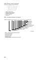
Skipping route waypoints
You may skip route waypoints by displaying
"DI" (DIsable) next to the route waypoint in
the route list. Using Figure 5-14 as an example, your ship is currently heading toward
waypoint 04 but is to switch course and head
to waypoint 03. In this case you would want
to skip waypoint 04.
,,
,,
,,
,,
,,,
,,,
,,,
,,,
Waypoint 03
Waypoint 04
5) Press the [NU/CU ENT] key.
5.2 Cancelling Destination
1) Press the [GOTO] key.
Waypoint 05
2) Press [5] to select Cancel. The message
shown in Figure 5-16 appears.
Release GOTO ?
Figure 5-14
1) Press [WPT RTE] and [5] to display the
route list. Press the cursor keys to select
route.
"EN" indicates waypoint
is enabled. Display "DI"
to skip waypoint.
ROUTE
4) Press [ ] to change "EN"(ENable) to
"DI"(DIsable).
New course
Waypoint 06
Port B
3) Press t or s to shift the cursor to the
right of the waypoint number.
To reselect the waypoint, select it on the route
list and press [ ] to change "DI" to "EN".
Waypoint 01
Waypoint 02
Port A
2) Press ▲ or ▼ to select route waypoint to
skip.
ENT:Yes
MENU:No
Figure 5-16
3) Press the [NU/CU ENT] key.
(In Use, REVERSE)
:01
skip Distance
TTG
001 Speed Auto Man (012.0kt)
Trial
01 0 04 EN
nm
D M H
02 0 03 EN 345.67nm
2D 12H 34M
004
34° 12.345' N 130° 23.456' E
MARINE POINT APR 10' 95 12:35U
003
36° 12.345' N
A POINT
: RTE
WPT
ENT:Enter
135° 23.456' E
APR 10' 95 13:45U
CLEAR: Delete
MENU:Escape
Figure 5-15 Route list
5–5
5.3 Erasing Route Waypoints
(flags)
1) Place the cursor on the flag to erase.
2) Press the [CLEAR] key. The message
shown in Figure 5-17 appears if the
waypoint is currently selected as destination, is part of a registered route, or is part
of the route currently being navigated.
1st line
Are you sure to erase ?
ENT:Yes MENU:No
When flags are erased
When the origin waypoint is erased the
waypoint before it becomes the origin
waypoint. If there is no waypoint before the
origin waypoint, current position becomes the
origin waypoint.
Delete
Starting
point
Destination
waypoint
Course
Own
ship
This wpt is GOTO
This wpt is in registered route
This wpt is in selected route
Figure 5-17
Destination
waypoint
3) Press the [NU/CU ENT] key.
Note: Flags can be erased collectively by clearing the Plotter memory or both the Plotter memory
and GPS memory. See page 9-1 for further details.
Figure 5-18 Route rearranged
after erasing flag
When a destination is erased, the waypoint
which follows it becomes the destination. If
there is no waypoint after the destination
waypoint erased, route navigation is cancelled.
5–6
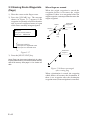
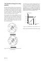
5.4 Finding Range and
Bearing Between Two Points
Selecting Course Sailing Method
The range and bearing to a destination are calculated by two ways: Great Circle or Rhumb
Line. However, cross track error is calculated
by rhumb line only.
Great Circle: The great circle courseline is
the shortest course between two points on the
surface of the earth. (Imagine stretching a
piece of yarn between two points on the earth.)
However, this course requires frequent change
of heading to follow course faithfully.
Rhumb Line: The rhumb line courseline is
the straight line drawn between two points on
a nautical chart. This course does not require
frequent changes of heading however it is not
the shortest since it follows the earth's curvature.
1) Press [MENU ESC] [9] and [1] to display the PLOTTER SETUP menu.
PLOTTER SETUP
Memory Apportion
Trk = 1000 / 2000Pt
Bearing Ref.
True
Mag Variation
Auto
(07° W)
Calculation
R.L
User defined #1
Man
(00° E)
G.C
User defined #2
SPD
CRS
User defined #3
RNG
User defined #4
BRG
ENT:Enter
Mag
MENU:Escape
Calculation Procedure
You can find the range and bearing between
two points by two waypoints or two latitude
and longitude positions.
1) Press [MENU ESC] and [5]. The
MANUAL CALCULATION menu appears.
MANUAL CALCULATION
From Waypoint No.
.
’N
.
’E
To
Waypoint No.
.
’N
.
’E
Trial speed : Auto
Man
(
. kt)
Rng :
. m
Brg :
.
TTG : D H M
: Cursor
ENT : Calculation
MENU : Escape
: N/S, E/W
Figure 5-20 MANUAL
CALCULATION menu
2) Choose two points by one of the methods
below.
Latitude and longitude positions
1) Press ▼.
2) If necessary press to switch from
North latitude and to South latitude
vice versa.
3) Key in latitude.
4) If necessary press to switch from West
longitude to East longitude and vice
versa.
5) Key in longitude.
6) Press ▼.
Figure 5-19 PLOTTER SETUP menu
7) Repeat 2-5 to enter other point.
2) Press ▲ or ▼ to selection Calculation.
Waypoints
3) Press t or s to select R.L (Rhumb Line)
or G.C (Great Circle).
1) Key in first waypoint number (001999). (000 is reserved for own ship
position.)
4) Press the [NU/CU ENT] key.
5) Press the [MENU ESC] key.
2) Press ▼ twice.
3) Key in other waypoint number (001999).
(Continued on next page)
5–7
3) Press ▼ to shift the cursor to the Trial
Speed line.
4) Press t or s to select Auto or Man.
Auto uses ship's average speed to calculate time-to-go.
5) If you selected Man, enter speed.
6) Press the [NU/CU ENT] key.
The range, bearing and time-to-go between
two points appear on the display. If data entered is wrong or insufficient the buzzer
sounds and the message "INCOMPLETE
DATA" appears. If the data contains error, "*"
and all nines appear as the calculation results.
7) Press the [MENU ESC] key.
5–8
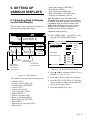
6. SETTING UP
VARIOUS DISPLAYS
6.1 Selecting Data to Display
on the Data Display
The user may select what data to display in
four locations on the data display.
SEP 12, 1995 23:59'59" U
POSITION
WGS72
DGPS 3D
TO : 001
BRG
31.23 nm
SPD
NEXT
CSE
12.3
kt
MARINE
POINT1
223.4°
123.4°
# Requires external sensor
PLOTTER SETUP
Memory Apportion
Trk = 1000 / 2000Pt
Bearing Ref.
True
Mag Variation
Auto
(07° W)
: 002
MARINE
POINT2
User-defined
User-defined
display data #1 display data #4
User-defined
display data #2
*ALT: Displayed only in 3D position fixing.
*RT. DIST: Total distance from current position
to ultimate destination. Appears when following
a registered route or a cursor-created route.
*VTD: When following a route, plus or minus
appears next to indication to denote which
direction the route is being traversed.
1) Press [MENU ESC] [9] and [1] to display the PLOTTER SETUP menu.
12° 23.456' N
123° 23.456' E
RNG
• Total route distance (RT.DIST)*
• Trip distance (TRIP)
• Trip elapsed time (TRIP TM)
• Water temperature (W.TMP)#, and
• Velocity to destination (VTD)*
User-defined
display data #3
User-defined
display window
Calculation
Mag
Man
(00° E)
R.L
User defined #1
SPD
User defined #2
CSE
User defined #3
RNG
User defined #4
BRG
ENT:Enter
MENU:Escape
G.C
Figure 6-2 PLOTTER SETUP menu
Figure 6-1 Data display
2) Press ▲ or ▼ to select one of four of "User
defined" (#1, #2, #3, #4).
The data the user may select to display are;
3) Press t or s to select data to display.
• Altitude (ALT)*
• Average course (AVR CSE)
• Average speed (AVR SPD)
• Course (CSE)
• Course error (dCSE)
• Cross track error (XTE)
• Depth (W.DPT)#
• ETA to waypoint (ETA)
• Range to waypoint (RNG)
• Route time-to-go (RT.TTG)
• Speed (SPD)
• Time-to-go to waypoint (TTG)
• ETA to route
4) Press the [NU/CU ENT] key. To select the
data to display at other user defined displays, repeat steps 2 and 3.
5) Press the [MENU ESC] key.
6–1
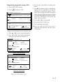
6.2 Selecting Position Format
1 For Loran LOPs
Position can be displayed in latitude and longitude, Loran C LOPs, or Decca LOPs, and
the default format is latitude and longitude.
6) Press ▼ to select LC Chain.
Selecting position format (L/L or
LOPs)
1) Press [MENU ESC] [9] and [8] to display the LOP SETUP menu.
8) Key in secondary code pair referring to
the Loran C chain list in the Appendix.
9) Press ▼.
10) Key in correction value.
LOP SETUP
Lat / Long
Pos Display
LOP
LOP Display
LC
DE
LC Chain
7980 : 23-43
LOP
-12.3us +0.34 us
DE Chain
24:G - P
LOP
+0.80 Lane -1.00 Lane
(RED:1 GREEN:2 PURPLE:3)
: Select
MENU : Escape
7) Key in GRI code referring to the Loran C
chain list appears in the Appendix. If the
GRI code is 9970, for example, press [9]
[9] [7] [0].
ENT : Enter
: +/–
Figure 6-3 LOP SETUP menu
2) Press ▲ or ▼ to select Pos Display.
11) If necessary, press [ ] to switch from
plus to minus or vice versa.
12) Press the [NU/CU ENT] key.
13) Press the [MENU ESC] key.
2 For Decca LOPs
6) Press ▼ to select DE Chain.
7) Key in Decca chain number referring to
the Decca chain list in the Appendix. For
the Europe chain, for example, press [0]
[1].
3) Press t or s to select Lat/Long or LOP.
8) Key in Decca lane pair. Red, [1]; Green
[2], and Purple [3].
4) Press the [NU/CU ENT] key.
9) Press ▼.
Displaying LOPs
10) Key in lane correction value.
1) Press [MENU ESC] [9] and [8].
11) If necessary, press [ ] to switch from
plus to minus or vice versa.
2) Press ▲ or ▼ to select Pos Display.
3) Press t or s to select LOP.
4) Press ▼ to select LOP Display.
5) Press t or s to select LC (Loran C) or
DE (Decca).
Follow 1 or 2 in the adjacent column according to selection in step 5.
6–2
12) Press the [NU/CU ENT] key.
13) Press the [MENU ESC] key.
Registering waypoints using LOPs
1) Press [WPT RTE] and [4].
6) Press ▼ to calculate LOPs. "Calculating"
appears between parentheses during the
calculation. Actual LOPs replace "Calculating" upon completion of the calculation.
] to display LOPs.
2) Press [
WAYPOINT LIST (LOP, LC)
001 36365.2
59102.3
MARINE POINT AUG12' 95 12 : 35U
002 36512.3
___ A POINT
59134.5
AUG13'
95 13 : 45U
8) Press the [NU/CU ENT] key.
004 _ _ _ _ _ , _
_____,_
___ _ _ _ _ _ _ _ _ _ _ _ _
LOP
ENT : Enter
If the conversion fails, the message "Failed
in Conversion" appears for three seconds.
Press the [CLEAR] key and reenter the
right LOP1 and LOP2.
7) Press t or s to select mark.
003 _ _ _ _ _ , _
_____,_
___ _ _ _ _ _ _ _ _ _ _ _ _
: L/L
5) Key in LOP1 and LOP2, to enable calculation.
9) Enter comment, if desired.
: Edit
MENU : Escape
10) Press the [NU/CU ENT] key twice.
Waypoint data and date and time registered appear.
Figure 6-4 LOP display on the waypoint list
3) Press ▲ or ▼ to select waypoint number.
4) Press t or s. Your display should look
like one of the displays in Figure 6-5.
Edit=Waypoint : 001
LC8930 :
30
50
58654.3
33 8931.2
(34° 12.345' N 130° 23.456' E)
Mark :
Cmnt : MARINE POINT
: Cursor
ENT : Enter
: Column
MENU : Escape
Loran C LOP input screen
Edit=Waypoint : 001
DE : 32 (9C) RED
GREEN
11 A:12.23
2H:24.35
(34° 12.345' N 130° 23.456' E)
Mark :
Cmnt : MARINE POINT
ABCDEFGHIJ fi 1, 2 ~ 9, 0
: Cursor
: Column
ENT : Enter
MENU : Escape
Decca LOP input screen
Figure 6-5 LOP input screens
6–3
6.3 Demo Display
The demo display provides simulated operation of this unit. Own ship tracks, at the speed
selected, a figure eight course, starting from
position entered. All controls are operative;
you may change course, enter marks, etc.
1) While pressing and holding down [NU/CU
ENT], turn on the power. After the test results appear, the Simulation Mode menu
appears.
DEMO SETTING
BASE POSITION
_ _° _ _._ _ _' N _ _ _°_ _._ _ _' W
SPEED
00.00kt
: Cursor
ENT: Enter
: Column
: N/S, E/W
Figure 6-6 Simulation mode menu
2) Key in latitude of initial position.
3) If necessary, press [ ] to switch from
north latitude to south latitude or vice
versa.
4) Key in longitude.
5) If necessary, press [ ] to switch from east
longitude to west longitude or vice versa.
6) Press ▼ key.
7) Key in speed.
8) Press the [NU/CU ENT] key to start the
simulation mode.
The icon
appears in the plotter 1, 2,
and highway display. All controls are operative.
Note: The return to the normal mode, turn off
the power and then turn it on while pressing
and holding down [NU/CU ENT] key.
Note: When the memory is cleared while in
the demonstration mode, the equipment starts
up in the normal mode.
6–4
1) Press the [MENU ESC] key.
7. ALARMS
2) Press [4] to display the ALARM SETTINGS menu.
There are seven alarm conditions which generate both audible and visual alarms.
When an alarm setting is violated, the buzzer
sounds and the name of the offending alarm
appears on the display. The alarm icon also
appears on the Plotter 1, Plotter 2 and Highway displays.
ALARM SETTINGS
Arrival/Anchor
Alarm Range
XTE
Alarm Range
Ship Speed
Speed Rage
Next Page
1/2
Arr.
Anc.
Off
0.100nm
On
Off
0.050nm
Over
In
Over Off
000.0 ~ 025.0kt
: Select
34° 23.456´ N 135° 45.678´ E
DGPS 3D
ENT : Enter
MENU : Escape
BRG
234°
Alarm message
CSE
345°
Alarm
icon
Arrival alarm
Speed alarm
RNG
123
Press CLEAR to silence beep
nm
SPD
12.3 kt
Press
Figure 7-3 ALARM SETTINGS
menu, page 1/2
3) Press ▲ or ▼ to select Arrival/Anchor.
4) Press t or s to select Arr.
5) Press ▼ to select Alarm Range.
6) Key in alarm range (0.001–9.999 nm).
7) Press the [NU/CU ENT] key.
CLEAR
8) Press the [MENU ESC] key.
Press CLEAR to close window
Figure 7-1 Location of alarm
messages and alarm icon
7.1 Arrival Alarm, Anchor
Watch Alarm
When own ship nears a waypoint by the range
set here, the buzzer sounds and the message
"Arrival alarm" appears. You can silence the
audible alarm by pressing the [CLEAR] key.
To erase the visual alarm, press the [CLEAR]
key again.
To disable the alarm, select Off at step 4.
Arrival alarm
The arrival alarm informs you that own ship
is approaching a destination waypoint. The
area that defines an arrival zone is that of a
circle which you approach from the outside
of the circle. The alarm will be released if own
ship enters the circle.
Alarm
setting
Own ship's
position
Destination
waypoint
: Alarm range
Figure 7-2 How the arrival alarm works
7–1
Anchor watch alarm
The anchor watch alarm sounds to warn you
that own ship is moving when it should be at
rest.
Alarm
setting
Own ship's
position
: Alarm range
Destination
waypoint
7.2 Cross Track Error (XTE)
Alarm
The XTE alarm warns you when own ship is
off its intended course.
Starting
waypoint
Own ship's
position
Alarm
setting
Destination
waypoint
: Alarm range
Figure 7-4 How the anchor
watch alarm works
Before setting the anchor watch alarm, set
present position as destination waypoint, referring to chapter 5.
1) Press [MENU ESC] and [4].
2) Press ▲ or ▼ to select Arrival/Anchor.
3) Press t or s to select Anc.
4) Press ▼ to select Alarm Range.
5) Key in alarm range (0.001–9.999 nm).
6) Press the [NU/CU ENT] key.
7) Press the [MENU ESC] key.
When own ship drifts by the range set here,
the buzzer sounds and the message "Anchor
alarm" appears. You can silence the audible
alarm by pressing the [CLEAR] key. To erase
the visual alarm, press the [CLEAR] key
again.
To disable the alarm, select Off at step 3.
7–2
Figure 7-5 How the XTE alarm works
1) Press [MENU ESC] and [4].
2) Press ▲ or ▼ to select XTE.
3) Press t or s to select On.
4) Press ▼ to select Alarm Range.
5) Key in alarm range (0.001–9.999 nm).
6) Press the [NU/CU ENT] key.
7) Press the [MENU ESC] key.
When own ship strays from the intended track
by the range set here, the buzzer sounds and
the message "Cross track error alarm" appears.
You can silence the audible alarm by pressing the [CLEAR] key. To erase the visual
alarm, press the [CLEAR] key again.
To disable the alarm, select Off at step 3.
7.3 Ship’s Speed Alarm
7.4 Trip Alarm
The ship’s speed alarm sounds when ship's
speed is lower or higher (or within) the alarm
range set.
The trip alarm sounds when the distance run
is greater than the trip alarm setting.
1) Press [MENU ESC] and [4].
2) Press ▲ or ▼ to select Next Page. The
menu shown in Figure 7-6 appears.
2) Press ▲ or ▼ to select Ship Speed.
3) Press t or s to select In (or Over).
In: Alarm sounds when speed is within
range set.
Over: Alarm sounds when speed is higher
or lower than range set.
4) Press ▼ to select Speed Range.
5) Key in low speed.
6) Key in high speed.
1) Press [MENU ESC] and [4].
ALARM SETTINGS
To Previous Page
Trip (CLR:Reset)
Trip Range
Water Temp.
Temp. Range
Depth
Depth Range
DGPS Alarm
: Select
MENU : Escape
7) Press the [NU/CU ENT] key.
8) Press the [MENU ESC] key.
2/2
Off
On
Off
0123.00nm
In
Over Off
+12.0 ~ +15.0°C
In
Over Off
0003.0 ~ 0200.0ft
On
Off
ENT : Enter
: +/-
Figure 7-6 Alarm settings menu, page 2/2
When speed is higher or lower (or within) than
the speed set here, the buzzer sounds and the
message "Speed alarm" appears. You can silence the audible alarm by pressing the
[CLEAR] key. To erase the visual alarm, press
the [CLEAR] key again.
3) Press ▲ or ▼ to select Trip.
To disable the alarm, select Off at step 3.
6) Press ▼ to select Trip Range.
4) If necessary, press [CLEAR] to reset the
trip distance and trip elapsed time (see
page 6-1).
5) Press t or s to select On.
7) Key in trip range.
8) Press the [NU/CU ENT] key.
9) Press the [MENU ESC] key.
When the ship's distance run is higher than
the trip range set here, the buzzer sounds and
the message "Trip alarm" appears. You can
silence the audible alarm by pressing the
[CLEAR] key. To erase the visual alarm, press
the [CLEAR] key again.
7–3
7.5 Water Temperature Alarm
7.6 Depth Alarm
The water temperature alarm sounds when the
water temperature is higher or lower (or
within) the preset temperature. This alarm requires temperature signal from external equipment.
The depth temperature alarm sounds when the
depth is higher or lower (or within) the preset
depth. This alarm requires video sounder connection.
1) Press [MENU ESC] and [4].
2) Press ▲ or ▼ to select Depth.
2) Press ▲ or ▼ to select Water Temp.
3) Press t or s to select In (or Over).
4) Press ▼ to select Temp. Range.
5) Key in low temperature.
6) Key in high temperature.
7) Press the [NU/CU ENT] key.
8) Press the [MENU ESC] key.
When the water temperature is higher or lower
(or within) the preset value, the buzzer sounds
and the message "Water temp alarm" appears.
You can silence the audible alarm by pressing the [CLEAR] key. To erase the visual
alarm, press the [CLEAR] key again.
1) Press [MENU ESC] and [4].
3) Press t or s to select In (or Over).
4) Press ▼ to select Depth Range.
5) Key in low depth.
6) Key in high depth.
7) Press the [NU/CU ENT] key.
8) Press the [MENU ESC] key.
When the depth is higher or lower (or within)
the preset value, the buzzer sounds and the
message "Depth alarm" appears. You can silence the audible alarm by pressing the
[CLEAR] key. To erase the visual alarm, press
the [CLEAR] key again.
To disable the alarm, select Off at step 4.
To disable the alarm, select Off at step 4.
7.7 DGPS Alarm
The DGPS alarm sounds when the DGPS signal is lost. This alarm may be enabled or disabled as below.
1) Press [MENU ESC] and [4].
2) Press ▲ or ▼ to select DGPS Alarm.
3) Press t to select On, or sto select off.
4) Press the [NU/CU/ENT] key.
5) Press the [MENU ESC] key.
7–4
8. MENU SETTINGS
8.1 GPS Menu
Menu description
Fix mode
Two position fixing modes are available: 2D
and 2/3D. The 2D mode provides two dimensional position fixes (latitude and longitude
only) and is used when three satellites are in
line of sight of the GPS receiver.
The 2/3D mode switches between two and
three dimension position fixing automatically
depending on how many satellites (three or
four) are in light of sight of the GPS receiver.
Disable satellite
Every GPS satellite is broadcasting abnormal
satellite number(s) in the Almanac. Using this
information, the GPS receiver automatically
eliminates any malfunctioning satellite from
the GPS satellite schedule. However, the Almanac sometimes may not contain this information. You can disable an inoperative
satellite manually on the GPS SETUP menu.
may change randomly depending on receiving conditions and other factors. You can reduce this random variation by increasing the
smoothing. Like with latitude and longitude
smoothing, the higher the speed and course
smoothing the more smoothed the raw data.
If the setting is too high, however, the response
to speed and course change slows. For no
smoothing, enter "0." "5" is suitable for most
conditions.
Speed average
Calculation of ETA and TTG, etc. is based on
average ship’s speed over a given period. The
default setting is one minute.
Geodetic datum
Select the geodetic chart system you are using. WGS-84 (standard GPS chart system) and
NAD 27 can be directly selected. For other
charts, select "OTHER" and enter chart number referring to the geodetic chart list in the
Appendix.
Position offset
You may apply an offset to position generated by the internal GPS receiver, to compensate for difference between GPS position and
chart position.
GPS smoothing, position
Time difference
When the DOP or receiving condition is unfavorable, the GPS fix may change greatly,
even if the vessel is dead in water. This change
can be reduced by smoothing the raw GPS
fixes. A setting between 0 and 9 is available.
The higher the setting the more smoothed the
raw data, however too high a setting slows
response time to change in latitude and longitude. This is especially noticeable at high
ship’s speeds. "0" is the normal setting; increase the setting if the GPS fix changes
greatly.
The GPS system uses UTC time. If you would
rather use local time, enter the difference in
hours between local time and UTC. Use the
[+] and [–] keys for times later or earlier than
UTC, respectively.
Position
Enter ship's position when cold starting (no
satellite information in memory) the GPS receiver, to fix position faster. Accuracy should
be within 10°.
GPS smoothing, speed
During position fixing, ship’s velocity (speed
and course) is directly measured by receiving
GPS satellite signals. The raw velocity data
8–1
Selecting fix mode
Entering GPS speed smoothing
1) Press [MENU ESC] [9] and [6] to display the GPS SETUP menu.
1) Press [MENU ESC] [9] and [6].
GPS SETUP
Fix mode
Disable satellite
GPS Smoothing
Posn
Spd
Speed Average
To Next Page
2D
12
1/2
2/3D
(1-32)
0 0 0 (000-999 sec)
0 0 5 (000-999 sec)
01 minute
: Select
MENU : Escape
2) Press ▲ or ▼ to select Spd.
3) Enter smoothing factor in three digits
(001–999).
4) Press the [NU/CU ENT] key.
5) Press the [MENU ESC] key.
Entering speed averaging
ENT : Enter
1) Press [MENU ESC] [9] and [6].
2) Press ▲ or ▼ to select Speed Average.
Figure 8-1 GPS SETUP menu, page 1/2
2) Press ▲ or ▼ to select Fix mode.
3) Press t or s to select fix mode desired.
4) Press ▼ to change other settings, or press
[MENU ESC] to register settings and escape.
3) Enter smoothing factor in two digits (00–
99).
4) Press the [NU/CU ENT] key.
5) Press the [MENU ESC] key.
Entering geodetic datum
1) Press [MENU ESC] [9] and [6].
Disabling satellites
1) Press [MENU ESC] [9] and [6].
2) Press ▲ or ▼ to select Disable satellite.
3) Key in satellite number, in two digits (01–
32). Three sets of satellite numbers may
be entered.
4) Press the [NU/CU ENT] key. If an invalid
number is entered the buzzer sounds.
5) Press the [MENU ESC] key.
Note: To enable all disabled satellites, press the
[CLEAR] key at step 3. All satellite numbers on
the Disable satellite line are erased.
2) Press ▲ or ▼ to select Geodetic Datum
on page 2/2.
GPS SETUP
2/2
To Previous Page
Geodetic Datum WGS84 NAD27 OTHER
(005)
Posn Offset
0.000' N 0.000' E
Time Diff.
+09: 00
Posn
12° 36.789' N 112° 47.890' E
: Select
MENU : Escape
ENT : Enter
: +/—
Figure 8-2 GPS SETUP menu, page 2/2
Entering GPS position smoothing
1) Press [MENU ESC] [9] and [6].
2) Press ▲ or ▼ to select Posn.
3) Enter smoothing factor in three digits
(001–999).
4) Press the [NU/CU ENT] key.
5) Press the [MENU ESC] key.
8–2
3) Press t or s to select geodetic datum to
use. For geodetic datum other than WGS72 or NAD-27, select OTHER and key in
chart number (001–173) referring to the
geodetic chart list in the Appendix.
4) Press the [NU/CU ENT] key.
5) Press the [MENU ESC] key.
Entering position offset
If you do not know the type of chart you are
using, GPS position may be wrong. Note the
difference in position when moored to a pier
and enter it on the GPS SETUP menu, to get
correct position.
4) If necessary, press [ ] to switch from east
longitude to west longitude or vice versa.
Key in longitude.
5) Press the [NU/CU ENT] key.
6) Press the [MENU ESC] key.
1) Press [MENU ESC] [9] and [6].
2) Press ▲ or ▼ to select Posn Offset on page
2/2.
8.2 Selecting Units of
Measurement
3) If necessary press [ ] to switch from
north latitude to south latitude or vice
versa.
Unit of distance
4) Key in latitude correction.
Distance can be displayed in nautical mile,
kilometer or statute mile as follows.
5) If necessary press [ ] to switch from east
longitude to west longitude or vice versa.
1) Press [MENU ESC] [9] and [2]. The
UNIT SETUP menu appears.
6) Key in longitude correction.
7) Press the [NU/CU ENT] key.
8) Press the [MENU ESC] key.
Entering time difference
UNIT SETUP
Unit of Distance
nm
km
sm
Unit of Depth
Unit of Temp.
Unit of Altitude
m
°C
ft
°F
FA
m
ft
1) Press [MENU ESC] [9] and [6].
2) Press ▲ or ▼ to select Time Diff on page
2/2.
:Select
ENT : Enter
MENU : Escape
3) Key in time difference (–14:00 to +14:00).
Figure 8-3 UNIT SETUP menu
4) Press [ ] to change from plus to minus
or vice versa.
2) Press ▲ or ▼ to select Unit of Distance.
5) Press the [MENU ESC] key.
3) Press t or s to select unit; nm, km or
sm.
4) Press the [NU/CU ENT] key.
Entering position
5) Press the [MENU ESC] key.
After the unit is installed you may enter position to shorten the time it takes to find position. (It takes about two minutes when there
is no position data entered.)
Unit of depth
1) Press [MENU ESC] [9] and [6].
2) Press ▲ or ▼ to select Unit of Depth.
2) Press ▲ or ▼ to select Posn on page 2/2.
3) Press t or s to select unit; meter, feet, or
fathom.
3) If necessary, press [ ] to switch from
north latitude to south latitude or vice
versa. Key in latitude.
4) Press the [NU/CU ENT] key.
1) Press [MENU ESC] [9] and [2].
5) Press the [MENU ESC] key.
8–3
Unit of water temperature
3) Press t or s to select brilliance.
1) Press [MENU ESC] [9] and [2].
4) Press [NU/CU ENT] and [MENU ESC].
2) Press ▲ or ▼ to select Unit of Temp.
3) Press t or s to select unit; Centigrade or
Fahrenheit.
4) Press [NU/CU ENT] and [MENU ESC].
Course bar tone
The course bar can be displayed in light or
dark tone, or turned off.
1) Press [MENU ESC] and [1].
Unit of altitude
2) Press ▲ or ▼ to select Course Bar.
Available only in 3D mode.
3) Press t or s to select brilliance.
1) Press [MENU ESC] [9] and [2].
4) Press the [NU/CU ENT] key.
2) Press ▲ or ▼ to select Unit of Altitude.
5) Press the [MENU ESC] key.
3) Press t or s to select unit.
Time mark tone
4) Press the [NU/CU ENT] key.
The time mark can be displayed in light or
dark tone, or turned off.
5) Press the [MENU ESC] key.
1) Press [MENU ESC] and [1].
8.3 Mark, Character Size and
Brilliance
2) Press ▲ or ▼ to select Time Mark.
The DISPLAY SETUP menu lets you select
the size and brilliance of various markers.
4) Press the [NU/CU ENT] key.
Grid tone
The grid can be displayed in light or dark tone,
or turned off.
1) Press [MENU ESC] and [1]. The DISPLAY SETUP menu appears.
DISPLAY SETUP
Grid
Course Bar
mark
Time Mark
Waypoint Size
Cursor Size
Dark
Dark
Dark
Dark
Large
Large
Light
Light
Light
Small
Small
Off
Off
Off
: Select
ENT : Enter
MENU : Escape
Figure 8-4 DISPLAY SETUP menu
2) Press ▲ or ▼ to select Grid.
8–4
3) Press t or s to select brilliance.
5) Press the [MENU ESC] key.
Waypoint mark size
Enlarging characters
The size of the waypoint mark can be selected
to large or small.
The size of the indications of position or user
defined display areas can be enlarged on the
Data display.
Large waypoint mark
No icon
12
With icon
12
1) On the Data display, with no enlarged
characters, press the [CURSOR ON/OFF]
key to turn on the cursor.
2) Operate the cursor keys to select data to
enlarge in the window.
3) Press the [ZOOM IN] key.
Small waypoint mark
To switch character size from enlarged to normal, press the [ZOOM OUT] key at step 3.
Cursor
Position
SEP 12, 1995 23:59'59" U
Figure 8-5 Waypoint mark size
1) Press [MENU ESC] and [1].
2) Press ▲ or ▼ to select Waypoint Size.
3) Press t or s to select Large or Small.
4) Press [NU/CU ENT] and [MENU ESC].
WGS84
12° 23.456' N
123° 23.456' E
RNG
The size of the cursor can be selected to large
or small.
Small cursor
31.23 nm
SPD
223.4°
kt
123.4°
2) Press ▲ or ▼ to select Cursor Size.
3) Press t or s to select Large or Small.
: 002
MARINE
POINT2
User-defined
display window
ZOOM
OUT
N12°
1) Press [MENU ESC] and [1].
MARINE
POINT1
NEXT
CSE
SEP 12, 1995 23:59'59" U
Figure 8-6 Cursor size
TO : 001
BRG
12.3
Cursor size
Large cursor
POSITION
DGPS 3D
ZOOM
IN
DGPS 3D
POSITION
23.456'
E123°
23.456'
WGS84
4) Press the [NU/CU ENT] key.
5) Press the [MENU ESC] key.
Figure 8-7 How to enlarge indications on
the data display
8–5
8.4 Settings for Connection
of Navigator
Besides its fundamental function of displaying position, the GP-80 can also output various data to external equipment. Before
outputting data to external equipment, first
determine what data the external equipment
requires. Output only necessary data to ensure data will be output correctly.
All data transmitted by marine electronics
equipment are prefixed with a two character
code called a talker. The same talker must be
shared by the transmitting and receiving
equipment to transmit and receive data successfully. The GP-80 transmits data using the
GP (GPS talker), however it can also transmit using the Loran (LC) or Decca (DE) talker.
Because the GP talker is a relatively new system some early model equipment may not
recognize this talker.
DATA 1 output setting
1) Press [MENU ESC] [9] and [3]. The
DATA 1, 3 OUTPUT SETUP menu appears.
DATA 1, 3 OUTPUT SETUP
Data Fmt.
V1.5 V2.0 IEC
Talker ID
GP
LC
DE
Output Data (00-90 sec)81%
1. AAM:00 APA:00 APB:04 BOD:00
2. BWR:00 BWW:00 GGA:00 GLL:01
3. RMB:01 RMC:01 VTG:01 WCV:01
4. WNR:00 WPL:00 XTE:00 ZDA:01
5. ZLZ:00 ZTG:01 Rnn:00 RTE:00
DATA3. Log Pulse
200ppm 400ppm
200ppm
ENT : Enter
MENU : Escape
Settings shown here are default settings.
This line appears only when LOG is
selected by internal jumper wires.
Figure 8-8 DATA 1, 3 OUTPUT
SETUP menu
2) Press ▲ or ▼ to select Data Fmt.
8-6
3) Press t or s to select NMEA 0183
(V1.5 or V2.0) or IEC 61162-1.
4) Press the [NU/CU ENT] key. Talker ID
appears in reverse video.
5) Press t or s to select GP, LC or DE.
6) Press the [NU/CU ENT] key.
7) Enter Tx interval for each output data sentence in line 1. Tx interval is available in
00, 01, 02, 03, 04, 05, 06, 10, 15, 20, 30,
60 and 90 (seconds).
8) Press the [NU/CU ENT] key.
9) Enter Tx interval for each output data sentence in lines 2 through 5. Press the [NU/
CU ENT] key after setting each line.
For detailed information about Tx interval see
the installation manual. However, the settings
entered by the installer of the equipment
should not be changed unless absolutely necessary.
BWC and WNC are for great circle navigation and BWR and WNR are for rhumb line
navigation.
The total data output are shown by percentage on the third line. For best results the total
output should not exceed 90%; lengthen the
Tx interval of less important data to make the
total output less than 90%.
DATA 2 output setting
Setting DATA 4 to NMEA
1) Press [MENU ESC] [9] and [4]. The
DATA 2 OUTPUT SETUP menu appears.
The DATA 4 port connects to a personal computer, DGPS receiver or YEOMAN equipment.
DATA 2 OUTPUT SETUP
Data Fmt.
V1.5
V2.0
Talker ID
GP
LC
Output Data (00-90 sec)81%
IEC
DE
1. AAM:00 APA:00 APB:04 BOD:00
2. BWR:00 BWW:00 GGA:00 GLL:01
3. RMB:01 RMC:01 VTG:01
WCV:01
4. WNR:00 WPL:00
5. ZLZ:00 ZTG:01
ZDA:01
RTE:00
ENT : Enter
XTE:00
Rnn:00
1) Press [MENU ESC] [9] and [5]. The
DATA 4 I/O SETUP (1/2) menu appears.
DATA 4 I/O SETUP
DATA 4. Level
Data
To Next Page
: Select
MENU : Escape
Settings shown here are default settings.
Figure 8-9 DATA 2 OUTPUT
SETUP menu
2) Follow the procedure for setting DATA 1
output.
ENT : Enter
1/2
RS232C
RS232C
Out
RS422
Com. DGPS
: Select
MENU : Escape
Appears only when external
DGPS receiver is used.
Figure 8-10 DATA 4 I/O SETUP menu (1/2)
2) Press ▲ or ▼ to select Level.
DATA 3 output setting
The DATA 3 connector can output IEC 611621/NMEA 0183 data or log pulse. (For details,
see the Installation Manual.) For NMEA 0183,
IEC 61162-1 the same data output by DATA
1 is output from DATA 3.
For log pulse, select 200 or 400 pulse per second depending on the device connected.
1) Press [MENU ESC] [9] and [3].
2) Press ▲ or ▼ to select DATA 3. Log Pulse.
3) Press t or s to select log pulse of external equipment; 200ppm or 400ppm.
4) Press the [NU/CU ENT] key twice.
3) Press t or s to select level of external
equipment; RS232C or RS422.
4) Press the [NU/CU ENT] key.
5) Press t or s to select Out.
6) Press ▼ to select To Next Page. The DATA
4 I/O SETUP (2/2) menu appears.
DATA 4 I/O SETUP
<Out>
2/2
To Previous Page
Data Fmt.
V1.5 V2.0 IEC
Talker ID GP
LC
DE
Output Data
(00-90 sec)
81%
1. AAM:00 APA:00 APB:04 BOD:00
2. BWR:00 BWW:00 GGA:00 GLL:01
3. RMB:01 RMC:01 VTG:01 WCV:01
4. WNR:00 WPL:00 XTE:00 ZDA:01
5. ZLZ:00 ZTG:01 Rnn:00 RTE:00
ENT : Enter
MENU : Escape
Figure 8-11 DATA 4 I/O SETUP menu (2/2)
7) Follow "DATA 1 output setting" from step
2.
8-7
8.5 Receiving Data from
Personal Computer
Loading erases current data
Are you sure to load ?
Loading lighthouse/buoy data
ENT: Yes
Lighthouse data can be downloaded from a
personal computer, through the DATA 4 connector.
1) Press [MENU ESC] [9] and [5].
2) Press ▲ or ▼ to select Level.
3) Press t or s to select level of personal
computer; RS232C or RS422.
MENU:No
Figure 8-13
13) Press the [NU/CU ENT] key. The message shown in Figure 8-14 appears while
data is being loaded.
Now loading
Light House data !
4) Press the [NU/CU ENT] key.
5) Press s to select Com.
MENU:Stop
6) Press ▼ to select To Next Page. The DATA
4 I/O SETUP menu appears.
DATA 4 I/O SETUP <Com.>
2/2
To Previous Page
Baud Rate
9600 bps
L.House WPT/RTE WPT
Load Data
Command
Stop
Start
Save Data
WPT/RTE
Command
Stop
Start
ENT : Enter
: Select
MENU : Escape
Figure 8-12 DATA 4 I/O SETUP menu (2/2)
Figure 8-14
14) Operate the computer to output data.
When data is loaded, the cursor shifts to
Stop.
15) Press the [MENU ESC] key.
Stopping loading of data
1) Press the [MENU ESC] key. The message
shown in Figure 8-15 appears.
Are you sure to stop ?
ENT: Yes
MENU:No
7) Press ▲ or ▼ to select Baud Rate.
8) Press t or s to select baud rate; 4800bps,
9600bps, or 19200bps.
9) Press the [NU/CU ENT] key.
10) Press t to select L.House.
11) Press ▼ to select Command. Stop, on the
same line as Command, appears in reverse
video.
12) Press s to select Start. The message
shown in Figure 8-13 appears.
8–8
Figure 8-15
2) To quit loading, press the [NU/CU ENT]
key. The cursor shifts to Stop.
3) To start loading, select Start.
4) Press the [NU/CU ENT] key.
Viewing lighthouse/buoy data
To view lighthouse/bouy data on the display,
place the cursor on the lighthouse mark. Data
of the lighthouse/buoy appears at the top of
the display.
Loading waypoint/route
1) Do steps 1 through 9 in "Loading lighthouse/buoy data."
2) Press t or s to select WPT/RTE.
If data could not be loaded, the message
shown in Figure 8-19 appears.
Failed in loading
Invalid data
Press any key
3) Press ▼ to select Command. Stop, on the
same line as Command, appears in reverse
video.
4) Press sto select Start. The message shown
in Figure 8-16 appears.
Loading erases current data
and stops Route navigation
Are you sure to load?
ENT: Yes
MENU: No
Figure 8-19
Loading waypoint data from
YEOMAN equipment
1) Do steps 1 through 9 in "Loading lighthouse data."
2) Press t or s to select WPT.
3) Press ▼ to select Command.
Figure 8-16
5) Press the [NU/CU ENT] key. The message shown in Figure 8-17 appears.
Now loading
Waypoint/Route data !
MENU:Stop
Figure 8-17
6) Operate the computer to output data.
When data is loaded, the cursor shifts to
Stop.
7) Press the [MENU ESC] key. When data
is loaded successfully, The message in
Figure 8-18 appears.
4) Press s to select Start. The message shown
in Figure 8-20 appears.
Are you sure to load ?
ENT: Yes
MENU:No
Figure 8-20
5) Press the [NU/CU ENT] key. The message shown in Figure 8-21 appears.
Now loading
Waypoint data !
MENU:Stop
Figure 8-21
Loading ended successfully
Press any key
Figure 8-18
6) Operate the YEOMAN to output data.
When data is loaded, the cursor automatically shifts to "Stop". Waypoints are
loaded into empty areas. When the
waypoint area becomes full, the message
shown in Figure 8-22 appears.
Waypoint area is full !
Can't load any data
Press any key to stop
Figure 8-22
8–9
7) When the data is loaded, press [CU/NU
ENT] and [MENU ESC]. The message
shown in Figure 8-23 appears.
The number of valid and invalid
waypoints appears in the message.
Loading completed
Valid waypoint : 0
Invalid waypoint : 0
Press any key
Figure 8-23
8) Press the [MENU ESC] key twice.
11) Press the [NU/CU ENT] key. The message shown in Figure 8-25 appears while
data is being saved.
Now saving
Waypoint/Route data !
MENU:Stop
Figure 8-25
12) Save data at the computer.
13) Press the [MENU ESC] key. When data
is saved, the cursor shifts to Stop.
15) Press the [MENU ESC] key.
Saving data to personal computer
Waypoint and route data can be saved to a
personal computer.
1) Press [MENU ESC] [9] and [5].
2) Press ▲ or ▼ to select Level.
3) Press t or s to select level; RS232C or
RS422.
4) Press the [NU/CU ENT] key. "Data" appears in reverse video.
5) Press s to select Com.
8.6 DGPS Settings
A DGPS beacon receiver (built in or external) may be connected to the GP-80 to further refine position accuracy. Set up to receive
the DGPS beacon signal as follows.
Selecting DGPS station
The default setting is "manual".
Automatic
6) Press ▼ to select Next Page.
7) Press ▲ or ▼ to select Baud Rate.
8) Press t or s to select baud rate; 4800bps,
9600bps, or 19200bps.
9) Press ▼ to select Command (under the
Save Data line). Stop, on the same line as
Command, appears in reverse video.
10) Press s to select Start. The message
shown in Figure 8-24 appears.
Are you sure to save ?
ENT: Yes
MENU:No
The GR-800 can automatically select optimum reference station by feeding it position
data. If it takes more than 5 minutes to fix
DGPS position at the automatic mode, switch
to manual mode. Use at manual mode when a
external beacon receiver has no automatic
function of station selection.
1) Press [MENU ESC] [9] and [7] to display the DGPS SETUP menu.
Frequency appears when
"MAN" is selected.
DGPS SETUP
DGPS MODE
On
Off
Ref. Station
Station
Ref.
Auto
Man (ID=
Freq.
Baud Rate
)
288.0kHz
200 bps
Figure 8-24
ENT : Enter
8 – 10
: Select
MENU : Escape
Figure 8-26 DGPS SETUP menu
2) Set DGPS MODE On.
3) Press ▲ or ▼ to select Ref. Station.
4) Press t or s to select Auto.
5) Press the [NU/CU ENT] key.
6) Press the [MENU ESC] key.
Manual
Setup for external DGPS beacon
receiver
When an external DGPS beacon receiver is
connected to the DATA 4 connector, set up
the GP-80 according to specification of DPGS
beacon receiver connected as follows.
1) Press [MENU ESC] [9] and [5].
2) Press ▲ or ▼ to select Level.
Enter four digit ID number, frequency and
baud rate of station.
3) Press t or s to select level; RS232C or
RS422.
Reference
4) Press the [NU/CU ENT] key.
• ID number: Appendix at end of this manual
• Frequency, baud rate : "DGPS REFERENCE LIST"
1) Press [MENU ESC] [9] and [7] to display the DGPS SETUP menu.
5) Press t or s to select DGPS.
2) Set DGPS MODE On.
3) Press ▲ or ▼ to select Ref. Station.
4) Press t or s to select Man.
5) Enter four digit ID number. You can clear
an entry by the [CLEAR] key. If the number entered is invalid, the buzzer sounds
and the message "INVALID ID" appears
on the display for three seconds.
If there is no ID number, press the
[CLEAR] key.
6) Press ▼ to select To Next Page.
DATA 4 I/O SETUP "DGPS"
To Previous Page
First
MSB LSB
LSB
First Bit
Bit
Parity
EVEN ODD
Stop Bit
1
2
Baud Rate
4800
9600
2/2
NONE
: Select
ENT : Enter
MENU : Escape
Figure 8-27 DATA 4 I/O SETUP
"DGPS" 2/2 menu
6) Press the [NU/CU ENT] key.
7) Press ▲ or ▼ to select First Bit.
7) Enter frequency in four digits (283.5kHz
to 325.0kHz).
8) Press t or s to select first bit; MSB or
LSB.
8) Press the [NU/CU ENT] key. "Baud Rate"
appears in reverse video.
9) Press ▼ to select Parity.
9) Press t or s to select baud rate; 25, 50,
100 or 200bps.
10) Press the [MENU ESC] key.
10) Press t or s to select parity bit; EVEN,
ODD or NONE.
11) Press ▼ to select Stop Bit.
12) Press t or s to select stop bit; 1 or 2.
13) Press ▼ to select Baud Rate.
14) Press t or s to select baud rate; 4800
or 9600.
15) Press the [MENU ESC] key.
8 – 11
8.7 Displaying GPS Monitor
Displays
DGPS 3D
Aug 21 1995 23:59'59" U
Three GPS monitor displays provide GPS information:
• Satellite monitor which shows position of
GPS satellites
• Beacon receiver monitor which displays
DGPS beacon station information
• DGPS beacon station message monitor
which displays messages received from
beacon stations
BEACON STATION
NAME: _ _ _ _ _ _ _ _ _ _ _ _ _ _ _ _ _ _ _ _ _ _ _ _ _
Health: _
ID: _ _ _ _
Freq: _ _ _ . _ kHz
Bit Rate: _ _ _ bps
SNR: _ _ dB
Sig Strength: _ _ dB
DGPS DATA:
BEACON STATION:
Good
Good
:STATION MESSAGE
MENU:Escape
DGPS data and DGPS
station receiving condition
DGPS station
data
BEACON RECEIVER MONITOR
To display the GPS monitor displays;
1) Press [MENU ESC] [7].
2) Press [ ] to display the GPS monitor
you want to view.
Aug 21 1995 23:59'59" U
3) Press the [MENU ESC] to escape.
Message:
STATION IS OPERATING.
DGPS 3D
Number, bearing and elevation angle of all satellites
in view of the GPS receiver appear. Satellites being
used in fixing position are circled with a solid line;
satellites not being used in fixing position are circled
with a dashed line.
Satellite
distribution
:SATELLITES MONITOR
MENU:Escape
GPS fix
state
Fixing date and time
STATION MESSAGE
Aug 21 1995 23:59'59" U
N
DGPS 3D
SV (PRN)
24
01
W
12
08
31
09
30
E
19
18 16
S
:BEACON RCVR MONITOR
MENU:Escape
SNR
40
50
01
12
31
16
18
19
09
08
24
Return to SATELLITES
MONITOR
Figure 8-28 GPS monitor displays
DOP:1.5
Satellite number with circle
is used for positioning.
DOP value
Receive signal level
(When signal level is more than 35, it is
used for positioning.)
SATELLITES MONITOR
8 – 12
9. MAINTENANCE &
TROUBLESHOOTING
9.1 Clearing the Memory
The GP-80 has two memories: GPS memory
and plotter memory.
Clearing the plotter memory
The plotter memory holds plotted track and
mark data. When you clear the plotter
memory, all track and marks are cleared and
all corresponding defaults settings are restored.
1) Press [MENU ESC] [9] and [9] to display the CLEAR MEMORY menu.
Clearing the GPS memory
The GPS memory stores GPS information,
including the Almanac. When you clear the
GPS memory, all GPS information is erased.
1) Press [MENU ESC] [9] and [9] to display the CLEAR MEMORY menu.
2) Press ▲ or ▼ to select Clear GPS.
3) Press s to select Yes. The following message appears.
Setting for cold start
Are you sure to clear ?
ENT:Yes MENU:No
Figure 9-3
4) Press the [NU/CU ENT] key.
Clearing GPS and plotter memories
CLEAR MEMORY
To clear both GPS and plotter memories;
Clear Plotter
ClearGPS
GPS
Clear
No
No
Clear All
No
Yes
Yes
Yes
1) Press [MENU ESC] [9] and [9] to display the CLEAR MEMORY menu.
2) Press ▲ or ▼ to select Clear All.
: Select
MENU : Escape
Figure 9-1 CLEAR MEMORY menu
2) Press ▲ or ▼ to select Clear Plotter.
3) Press s to select Yes. The following message appears.
Clear tracks and marks
Are you sure to clear ?
ENT:Yes MENU:No
3) Press s to select Yes. The message shown
in Figure 9-4 appears.
Setting for default
Are you sure to clear ?
ENT:Yes MENU:No
Figure 9-4
4) Press the [NU/CU ENT] key.
Note: The equipment may lock after clearing the
GPS and plotter memories. Reapply power to the
equipment to restore normal operation.
Figure 9-2
4) Press the [NU/CU ENT] key.
9–1
9.2 Preventative Maintenance
9.3 Error Messages
Regular maintenance is necessary to maintain
performance. Check the items mentioned below monthly to keep the equipment in good
working order.
Error messages appear on the display to alert
you to possible trouble.
Antenna unit
WARNING
Do not open the display unit cover.
High voltage exists inside.
Check for fixing bolts for tightness.
If the unit is not working properly,
contact your dealer.
Antenna cable
Check connector for tightness, rust, damage and water leaks.
Power cable
GPS error
When GPS signal is suddenly lost and position cannot be calculated within one minute
the message shown in Figure 9-5 appears.
Check for tight connection.
GPS No fix
Ground terminal
Check for rust and tight connection.
Fuse
The 2A fuse in the power cable protects the
unit from overvoltage and equipment fault. If
the fuse blows, find out the cause before replacing the fuse. If the fuse blows after replacement, request service.
WARNING
Figure 9-5 GPS error message
This message may appear when there is an
interfering object between the satellite and
GPS receiver (for example, mast) or the antenna cable is disconnected.
DOP error
When PDOP value exceeds 6 in the 3D mode,
or HDOP value exceeds 4 in the 2D mode,
this error occurs and following indication appears.
Use only a 2A fuse in the power cable.
Use of different fuses may cause fire.
DOP Error
Figure 9-6 DOP error message
9–2
DGPS error
When DGPS data contains errors or the DGPS
beacon station is experiencing transmitting
problems, the message shown in Figure 9-7
appears.
DGPS Error
Figure 9-7 DGPS error message
Self test error message
If the self test (conducted when turning on
the power) finds equipment error, the message shown in Figure 9-8 appears.
GPS Self Test Error
Figure 9-8 Self test error message
If the self test error message appears, consult
your dealer for advice.
9–3
9.4 Troubleshooting
The table which follows provides troubleshooting procedures which you can follow to
restore normal operation. If normal operation
cannot be restored, ask your dealer for advice.
Table 9-1 Troubleshooting table
If...
Then...
you cannot turn on the
power
• check power connector for tight connection.
• check if ship's mains is off.
• check for blown fuse.
position cannot be fixed
• check antenna cable for tight connection and water leakage.
• check if functional satellite has been disabled: [MENU ESC] [9] [6]
position is wrong
• check if correct geodetic chart is entered: [MENU ESC] [9] [6]
• apply position correction to GPS position: [MENU ESC] [9] [6]
data cannot be transmitted
to external equipment
• check if data format is correct: [MENU ESC] [9] [3] [9] [4] [9] [5]
See the installation manual for further details.
• Tx interval may be set to "0". Select proper interval:
[MENU ESC] [9] [3] [9] [4] [9] [5]
See the installation manual for further details.
• Check appropriate settings on external equipment.
• Check connections:
GP-80
external equipment
TD-A
RD-A
TD-B
RD-B
9–4
9.5 Self Tests
Whenever NG or 16 hexadecimal figure
appears contact your dealer for advice.
Memory and I/O circuits test
DATA 1 PORT, DATA 2 PORT and DATA
4 PORT show results of communication
interface test. A special test connector is
required to test those ports. NG appears
as the results of the self test when there is
no test connector attached.
1) Press [MENU ESC] and [8] to display the
SELF TESTS menu.
SELF TESTS
1. Memory, I/O Port Test
2. Keyboard Test
3. Test Pattern
4. Automatic Testing
4) Press the [MENU ESC] key to escape.
Note: The life of the internal battery is approximately 5 years.
GPS PROGRAM No. 4850100
NAV PROGRAM No. 2051011
BOOT PROGRAM Code A
:Cursor
ENT:Enter
MENU:Escape
Figure 9-9 SELF TESTS menu
2) Press [1].
MEMORY, I/O PORT TEST
PROGRAM MEMORY
SRAM
Internal Battery
DATA 1 PORT
DATA 2 PORT
DATA 4 PORT
GPS
BEACON
OK
OK
OK
NG
NG
NG
OK
OK
Name
Type
Code No.
Lithium
CR2450-F2ST2L
000-144-941
Keyboard test
1) Press [MENU ESC] [8] and [2] to display the KEYBOARD TEST screen.
KEYBOARD TEST
MENU:Escape
Press CLEAR 3 times to escape
Figure 9-10 MEMORY, I/O PORT
TEST display
3) When testing is finished, press the [MENU
ESC] key to escape and return to the Self
Test menu. (Testing continues if the key
is not pressed.)
OK appears to the right of PROGRAM,
SRAM and Internal Battery when those
devices are normal; NG (No Good) appears when an abnormality is found.
Figure 9-11 KEYBOARD TEST screen
2) Press each key one by one. A key's corresponding location on the screen lights in
reverse video if the key is normal.
3) To quit the keyboard test, press the
[CLEAR] key three times. Control is returned to the SELF TESTS menu.
4) Press the [MENU ESC] key.
OK appears to the right of GPS and BEACON when they are normal; NG and 16
hexadecimal figure appear when an abnormality is found.
9-5
Display test
Automatic testing
1) Press [MENU ESC] [8] and [3] to display the test pattern screens.
This feature conducts all self tests continuously.
2) To change the test pattern, press the [NU/
CU ENT] key. Each time the key is
pressed one of the patterns shown in Figure 9-12 appears.
1) Press [MENU ESC] [8] and [4]. Self tests
are conducted continuously in the order
of memory, I/O test, keyboard test and test
pattern.
TEST PATTERN
2) To stop testing, press the [MENU ESC]
key.
3) Press the [MENU ESC] key.
ENT:Pattern MENU:Escape
Figure 9-12 Test patterns 1 and 2
3) To quit the test pattern, press the [CLEAR]
key three times. Control is returned to the
SELF TESTS menu.
4) Press the [MENU ESC] key.
9–6
10.2 How the GPS Receiver
Calculates Position
10. INTRODUCTION
TO GPS
The GPS receiver’s position is continuously
fixed by receiving 3 (or 4) satellites in lineof-sight of the GPS receiver. The basic steps
in position fixing are as below.
10.1 What is GPS?
1) GPS satellites continually transmit their
own precise orbital data called ephemeris.
The GPS receiver computes satellites’
position by this data.
GPS is an acronym meaning Global Positioning System. GPS (sometimes referred to as
NAVSTAR) is a highly precise satellite navigation system developed by the U.S. Department of Defense.
2) The GPS receiver measures very accurate
distance to the satellites.
When full global coverage becomes available,
a constellation of 24 satellites emplaced in
nearly 20,000-kilometer high 12-hour circular orbits will provide highly precise, continuous, worldwide, all-weather position plus time
and velocity information to GPS receiverequipped vehicles, vessels and aircraft.
d2
3) Satellite locations and their distances from
the GPS receiver are known. The GPS
receiver fixes its own position by triangulation.
d3
1 Satellite locations are
calculated.
2 Distances are measured.
d1
3 The GPS fix is the point
of intersection of three
spheres which are drawn
around the three satellites
with diameter d1, d3 , and d3.
GPS fix
Figure 10-1 How the GPS receiver calculates position
10 – 1
10.3 Position-fixing Accuracy
(HDOP)
In radar position-fixing, most accurate position fixes are obtained when the targets used
are spaced nearly 90° from each other. Similarly, GPS position fixing accuracy is subject
to satellite location. Generally, the further
apart the satellites are from one another, the
greater the position-fixing accuracy.
For example, take a look at Figure 10-2. In
both situations a fix is obtainable in the Northern Pacific region because three satellites are
in line-of-sight. However, accuracy will be
higher in the bottom figure since the satellites are spread farther apart than the satellites in the top figure.
The index for position-fixing accuracy is
known as HDOP (Horizontal Dilution of Precision) for 2D mode or PDOP for 3D mode.
In simpler terms it is the geometrical relationship among 3 (or 4) satellites. The higher the
HDOP value the less accurate the position fix.
The error in distance is proportional to the
HDOP value as shown in Figure 10-3.
ERROR (RMS)
60 m
45 m
30 m
15 m
DOP
3
6
9
12
Figure 10-3 HDOP rate and position error
Note: In this manual HDOP is referred to as DOP.
LOW ACCURACY
HIGH ACCURACY
Figure 10-2 Satellite positions and accuracy
of position fix
10 – 2
Specifications
GPS Receiver
Number of receiving channels
12 channels parallel, 12 satellite tracking
Rx frequency
1575.42MHz
Rx code
C/A code
Position fixing system
All in view, 8-state Kalman filter
Position Accuracy
Approx. 10m, 95% of the time, Horizontal dilution
of position (HDOP) ≤ 1
Note: All GPS receiver are subject to degradation
of position and velocity accuracies under the U.S.
Department of Defence. Position may be degraded.
DGPS: Approx. 5 m, 95% of the time
Tracking velocity
900 kts
Position-fixing time
Warm start: 12 seconds
Cold start: 90 seconds
Position update interval
1 second
Display Section
LCD
122 x 92 mm (320 x 240 dot matrix)
Display mode
Plotter modes 1 and 2, Highway, Navigation, Data
Display
Mercator projection
Track recording and mark capacity: 2,000 pts.
Lighthouse, buoy graphic (option)
YEOMAN waypoint display
Waypoint storage capacity
999 pts. with comment (12 character)
Route storage capacity
30 routes (30 waypoints per route)
Simple route: 1 route/30 waypoints
Alarms
Waypoint arrival, Anchor watch, Cross track error,
Speed, Trip, Water temperature, depth
(Continued on next page)
A–1
Data Input/Output
Number of ports
4 I/O ports
Data format
IEC 61162-1/NMEA 0183 Ver. 1.5/NMEA Ver. 2.0
Input data
• NMEA 0183: AGFPA, DBT, DPT, MTW, TLL
• DPGS; RTCM SC104 Ver. 2.1
• Universal data from personal computer.
Output data
IEC 61162-1/NMEA 0183 (Ver. 1.5/Ver. 2.0):
AAM, APA, APB, BOD, BWC, BWR, BWW,
GGA, GLL, RMB, RMC, VTG, WCV, WNC,
WNR, WPL, XTE, ZDA, ZLG, ZTG, Rnn, RTE,
DTM (IEC 61162-1)
Power Supply & Environmental Conditions
Power supply and power consumption
10.2 to 31.2V DC, less than 10 W
Useable environment
Antenna unit: -25°C to +70°C
Receiver unit:-15°C to +55°C
Beacon antenna unit:-20°C to +70°C
Humidity
95% (40°C)
Waterproofing specification
Antenna unit: IEC 529 1PX6
Display unit: IEC 529 1PX5 (USCG CFR-46)
Resistancy
1 to 12.5Hz: 3.2 mmpp
12.5 to 25Hz: 0.8 mmpp
25 to 50Hz: 0.2 mmpp
Dimensions and Weight
Dimenions
Antenna unit: ø62 x 67 mm
Display unit: 160 x 250 x 65mm
Beacon antenna unit: ø 64 x 212 mm
Mass
Antenna unit: 0.1 kg
Display unit: 2.2 kg
Beacon antenna unit: 0.6 kg
A–2
Digital Interface (IEC 61162-1)
Output sentences of channel 1, 2, 3, 4 (DATA 1, DATA 2, DATA 3, DATA 4)
AAM, APB, BOD, BWC, BWR, BWW, GGA, GLL, RMB, RMC, VTG, WCV, WNC, WPL,
XTE, ZDA, ZTG, RTE, DTM
Input sentences of channel 1 (DATA 1, DATA2, DATA4)
DBT, DPT, MTW, TLL
Transmission interval
All sentences output at the interval selected (00-90 s).
Load requirements as listener
Isolation: Optocoupler
Input impedance: 470 ohms
Max. voltage: ±15V
Threshold: 3 mA (in case of connection of FURUNO device talker)
Data transmission
Data is transmitted in serial asynchronous form in accordance with the standard referenced in
2.1 of IEC 61162-1. The first bit is a start bit and is followed by data bits.
The following parameters are used:
Baud rate: 4800
Data bits: 8 (D7 = 0), parity none
Stop bits: 1
D0
Start
bit
D1
D2
D3
D4
Data bits
D5
D6
D7
Stop
bit
A-3
Schematic diagrams
DATA1 port (output)
Output drive capability: Max. 10mA
20P8147
DATA 1
R107
FL1 27
J5
TD-A
TD-B
U35
AM26LS31CNS
MJ-A6SRMD
1
5
7
6
2
FL14
R101
27
6
DATA 1 port (input)
20P8147
DATA 1
MJ-A6SRMD
J5
+5V
1
2
RD-H
3
RD-C
4
5
6
A-4
Fl12
JP6
R108
390
FL11
R77
100
1
4
3
PC-400
U17 5
CR13
1SS226
R64
2.2K
DATA 2 port (output)
Output drive capability: Max. 10mA
20P8147
DATA2
MJ-A6SRMD
J7
TD-A
1
TD-B
2
3
FL9
R104
27
13
15
FL10
R105
27
4
14
U35
AM26LS31CNS
5
6
DATA 2 port (input)
20P8147
DATA2
MJ-A6SRMD
J7
+5V
1
2
RD-H
RD-C
JP7
FL8
3
R109
390
4
5
R76
100
FL7
1
3
4
PC-400
U28
R63
2.2K
5
CR14
1SS226
6
A-5
DATA 3 port (output)
Output drive capability: Max. 10mA
20P8147
DATA3
MJ-A6SRMD
J6
FL5 1
TD-A
1
TD-B
FL6
11
2
3
2
3
2
R102
27
4
JP4
R103
27
10
4
5
6
DATA 4 port
IN/OUT signal is selected by the menu among the output of IEC 61162-1, NMEA Ver. 1.5/2.0,
PC input/output and DGPS signal.
Sentence description
AAM - Waypoint arrival alarm
$--AAM,A,A,x.x,N,c--c*hh<CR><LF>
| | | | | |
| | | | | +--------- 5
| | | | +------------ 4
| | +---+---------------- 3
| +---------------------- 2
+------------------------ 1
1. Status: A=arrival circle entered
2. Status: A=perpendicular passed at waypoint
3. Arrival sircle radius, nautical miles
4. Waypoint ID
5. Checksum
A-6
APB - Autopilot sentence data
$--APB,A,A,x.x,a,N,A,A,x.x,a,c--c,x.x,a,x.x,a,a*hh<CR><LF>
| | | | | | | | | | | | | | | |
| | | | | | | | | | | | | | | +------- 13
| | | | | | | | | | | | | | +--------- 12
| | | | | | | | | | | | +--+----------- 11
| | | | | | | | | | +--+----------------- 10
| | | | | | | | | +------------------------ 9
| | | | | | | +--+---------------------------- 8
| | | | | | +---------------------------------- 7
| | | | | +------------------------------------ 6
| | | | +-------------------------------------- 5
| | | +---------------------------------------- 4
| | +------------------------------------------- 3
| +---------------------------------------------- 2
+------------------------------------------------ 1
1. Status: A=Data varid V=LORAN-C blink or SNR warning
V=general warning flag for other navigation systems
when a reliable fix is not available
2. Status: A=OK or not used
V=LORAN-C cycle lock warning flag
3. Magnitude of XTE(cross-track-eror)
4. Direction to steer,L/R
5. XTE units, nautical miles
6. Status: A=arrival circle entered
V=arrival circle not passed
7. Status: A=perpendicular passed at waypoint
V=perpendicular not entered
8. Bearing origin to destination, M/T
9. Destination waypoint ID
10. Bearing, present potition to destination, magnetic or true
11. Heading to steer to destination waypoint, magnetic or true
12. Mode indicator(see Note)
13. Checksum
NOTE Positioning system Mode indicator:
A = Autonomous mode
D = differential mode
S = Simulator mode
N = Data not valid
A-7
BOD - Bearing, origin to destination
$--BOD,x.x,T,x.x,M,c--c,c--c*hh<CR><LF>
| | | | |
| |
| | | | |
| +--------- 5
| | | | | +------------ 4
| | | | +----------------- 3
| | +--+--------------------- 2
+--+--------------------------- 1
1. Bearing, degrees true
2. Bearing, degrees magnetic
3. Destination waypoint ID
4. Origin waypoint ID
5. Checksum
BWC - Bearing and distance to waypoint
$--BWC, hhmmss.ss, llll.ll, a yyyyy.yy, a, x.x, T, x.x, M, x.x, N, c--c, a*hh<CR><LF>
Checksum
Mode indicator
(see note 1)
Waypoint ID*
Distance, nautical miles
Bearing, degrees magnetic*
Bearing, degrees true
Waypoint longitude, E/W*
Waypoint latitude, N/S*
UTC of observation*
*: Not used
NOTE 1: Positioning system Mode indicator:
A= Autonomous mode
D= Differential mode
S= Simulator mode
N= Data not valid
The Mode indicator field shall not be a null field.
A-8
BWR - Bearing, waypoint to range
$--BWR,hhmmss.ss,llll.lll,a,yyyyy.yyy,a,x.x,T,x.x,M,x.x,N,c--c,a*hh<CR><LF>
|
| |
|
| | | | | | | | | |
|
| |
|
| | | | | | | | | +---- 9
|
| |
|
| | | | | | | | +------ 8
|
| |
|
| | | | | | | +--------- 7
|
| |
|
| | | | | +--+------------- 6
|
| |
|
| | | +--+------------------- 5
|
| |
|
| +--+------------------------- 4
|
| |
+-----+------------------------------- 3
|
+-----+------------------------------------------- 2
+---------------------------------------------------------- 1
1. UTC of observation
2. Waypoint latitude, N/S
3. Waypoint longitude, E/W
4. Bearing, degrees true
5. Bearing, degrees magnetic
6. Distance, nautical miles
7. Waypoint ID
8. Mode indicator(see note)
9. Checksum
NOTE Positioning system Mode indicator:
A = Autonomous mode
D = differential mode
S = Simulator mode
N = Data not valid
The Mode indicator field shall not be a null field.
BWW - Bearing, waypoint to waypoint
$--BWW,x.x,T,x.x,M,c--c,c--c*hh<CR><LF>
| | | | |
| |
| | | | |
| +--------- 5
| | | | | +------------ 4
| | | | +----------------- 3
| | +--+--------------------- 2
+--+--------------------------- 1
1. Bearing, degrees true
2. Bearing, degrees magnetic
3. TO waypoint ID
4. FROM waypoint ID
5. Checksum
A-9
DBT - Depth below transducer
$--DBT,x.x,f,x.x,M,x.x,F*hh<CR><LF>
| | | | | | |
| | | | | | +--------- 4
| | | | +--+----------- 3
| | +--+----------------- 2
+--+----------------------- 1
1. Water depth, feet
2. Water depth, m
3. Water depth, fathoms
4. Checksum
DPT - Depth
$--DPT,x.x,x.x,x.x*hh<CR><LF>
| | | |
| | | +----- 4
| | +--------- 3
| +------------ 2
+---------------- 1
1. Water depth relative to trancsducer, in meters
2. Offset from transeducer, in meters(see notes 1 and 2)
3. Maximum range scale in use
4. Checksum
NOTE1 "positive"=distance from transeduser to water-line.
"-"=distance from transducer to keel.
NOTE2 For IEC applications the offset should always be applied
so as to provide depth relative to the keel.
DTM - Datum reference
$--DTM,ccc,a,x.x,a,x.x,a,x.x,ccc*hh<CR><LF>
| | | | | | | | |
| | | | | | | | +--- 7
| | | | | | | +------ 6
| | | | | | +---------- 5
| | | | +--+------------- 4
| | +--+------------------- 3
| +------------------------- 2
+---------------------------- 1
1. Local datum W84 - WGS84
W72 - WGS72
S85 - SGS85
P90 - PE90
999 - User defined
IHO datum code
2. Local datum subdivision code
3. Lat offset, min, N/S
4. Lon offset, min, E/W
5. Altitude offset, m
6. Reference dattum W84 - WGS84
W72 - WGS72
S85 - SGS85
P90 - PE90
7. Checksum
A-10
GGA -Global positioning system fix data
$--GGA,hhmmss.ss,llll.lll,a,yyyyy.yyy,a,x,xx,x.x,x.x,M,x.x,M,x.x,xxxx*hh<CR><LF>
|
| |
|
| | | | | | | | |
| |
|
| |
|
| | | | | | | | |
| +-- 11
|
| |
|
| | | | | | | | | +---- 10
|
| |
|
| | | | | | | | +--------- 9
|
| |
|
| | | | | | +---+------------ 8
|
| |
|
| | | | +---+------------------ 7
|
| |
|
| | | +------------------------- 6
|
| |
|
| | +---------------------------- 5
|
| |
|
| +------------------------------- 4
|
| |
+----+--------------------------------- 3
|
+---+--------------------------------------------- 2
+------------------------------------------------------------- 1
1. UTC of position
2. Latitude, N/S
3. Longitude, E/W
4. GPS quality indicator (0: No fix, 1: GPS, 2: Differential, 8: Demo mode)
5. Number of satllite in use,00-12, may be different from the number in view
6. Horizontal dilution of precision
7. Antenna altitude above/below mean sealevel, m
8. Geoidal separation, m
9. Age of differential GPS data
10. Differential reference station ID, 0000-1023
11. Checksum
GLL - Geographic position, latitude and longitude
$--GLL,llll.lll,a,yyyyy.yyy,a,hhmmss.ss,A,a*hh<CR><LF>
| |
|
|
|
| | |
| |
|
|
|
| | +------- 6
| |
|
|
|
| +--------- 5
| |
|
|
|
+----------- 4
| |
|
|
+---------------- 3
| |
+------+----------------------- 2
+---+----------------------------------- 1
1. Latitude, N/S
2. Longitude, E/W
3. UTC of position
4. Status: A=data valid, V=data invalid
5. Mode indicator(see note)
6. Checksum
NOTE Positioning system Mode indicator:
A = Autonomous
D = Differential
S = Simulator
N = Data not valid
The Mode indicator field supplements the Status field. The Status field shall be
set to V=invalid for all values of Operating Mode except for A=Autonomous and
D=Differential. The positioning system Mode indicator and Status field shall not
be null fields.
A-11
MTW- Wind speed and angle
$--MTW,x.x,C*hh<CR><LF>
| | |
| | +--------- 2
+--+----------- 1
1. Temperature, degrees C
2. Checksum
RMB - Recommended minimum navigation information
$--RMB,A,x.x,a,c--c,c--c,llll.lll,a,yyyyy.yyy,a,x.x,x.x,x.x,A,a*hh<CR><LF>
| | | |
| | |
|
| | | | | | |
| | | |
| | |
|
| | | | | | +--- 13
| | | |
| | |
|
| | | | | +----- 12
| | | |
| | |
|
| | | | +------- 11
| | | |
| | |
|
| | | +---------- 10
| | | |
| | |
|
| | +-------------- 9
| | | |
| | |
|
| +------------------ 8
| | | |
| | |
+-----+--------------------- 7
| | | |
| +----+--------------------------------- 6
| | | |
+--------------------------------------------- 5
| | | +-------------------------------------------------- 4
| | +------------------------------------------------------ 3
| +--------------------------------------------------------- 2
+------------------------------------------------------------ 1
1. Data status: A=data valid, V=navigation receiver warning
2. Cross track error(see note 2) n.miles
3. Direction to steer L/R
4. Origin waypoint ID
5. Destination waypoint ID
6. Destination waypoint latitude,N/S
7. Destination waypoint longitude,E/W
8. Range to destination, n.miles(see note 1)
9. Bearing to destination, degrees true
10. Destination closing velocity, knots
11. Arrival status: A=arrival circle entered or perpendicular passed
12. Mode indicator(see note 3)
13. Checksum
NOTES
1 If range to destination exceeds 999.9 nautical miles, display 999.9.
2 If cross track error exceeds 9.99 nautical miles, display 9.99.
3 Positioning system Mode indicator:
A = Autonomous
D = Differential
S = Simulator
N = Data not valid
The Mode indicator field supplements the Status field. The Status field
shall be set to V=invalid for all values of Operating Mode except for
A=Autonomous and D=Differential. The positioning system Mode indicator
and Status field shall not be null fields.
A-12
RMC- Recommended minimum specific GPS/TRANSIT data
$--RMC,hhmmss.ss,A,llll.lll,a,yyyyy.yyy,a,x.x,x.x,xxxxxx,x.x,a,a*hh<CR><LF>
|
| | |
|
| | |
|
| | | |
|
| | |
|
| | |
|
| | | +--- 10
|
| | |
|
| | |
|
| | +----- 9
|
| | |
|
| | |
|
+--+------- 8
|
| | |
|
| | |
+--------------- 7
|
| | |
|
| | +--------------------- 6
|
| | |
|
| +------------------------- 5
|
| | |
+---+---------------------------- 4
|
| +---+---------------------------------------- 3
|
+--------------------------------------------------- 2
+---------------------------------------------------------- 1
1. UTC of position fix
2. Status: A=data valid, V=navigation receiver warning
3. Latitude, N/S
4. Longitude, E/W
5. Speed over ground, knots
6. Course over ground, degrees true
7. Date: dd/mm/yy
8. magnetic variation, degrees E/W
9. Mode indicator(see note)
10. Checksum
NOTE Positioning system Mode indicator:
A = Autonomous
D = Differential
S = Simulator
N = Data not valid
The Mode indicator field supplements the Status field. The Status field
shall be set to V=invalid for all values of Operating Mode except for
A=Autonomous and D=Differential. The positioning system Mode indicator
and Status field shall not be null fields.
RTE - Routes
$--RTE,x.x,x.x,a,c--c,c--c,.....,c--c*hh<CR><LF>
| | | |
|
| |
| | | |
|
| +--------- 7
| | | |
|
+------------ 6
| | | | +----------------------- 5
| | | +---------------------------- 4
| | +-------------------------------- 3
| +----------------------------------- 2
+--------------------------------------- 1
1. Total number of messages being transmitted
2. Message number
3. Message mode:
c=complete route, all waypoints
w=working route, first listed waypoint is "FROM",
second is "TO" and remaining reset of route
4. Route identifier
5. Waypoint identifier
6. Waypoint "n" identifier
7. Checksum
A-13
TLL - Target latitude and longitude
$--TLL,xx,llll.lll,a,yyyyy.yyy,a,c--c,hhmmss.ss,a,a*hh<CR><LF>
| | |
|
| |
|
| | |
| | |
|
| |
|
| | +--------- 8
| | |
|
| |
|
| +----------- 7
| | |
|
| |
|
+------------- 6
| | |
|
| |
+-------------------- 5
| | |
|
| +-------------------------- 4
| | |
+-----+------------------------------ 3
| +----+------------------------------------------ 2
+----------------------------------------------------- 1
1. Target number 00 - 99
2. Latitude, N/S
3. Longitude, E/W
4. Target name
5. UTC of data
6. Target status(see note)
7. Reference target=R,null otherwise
8. Checksum
NOTE - Target status
L = lost,tracked target has beenlost
Q = query,target in the process of acquisition
T = tracking
VTG - Course over ground and ground speed
$--VTG,x.x,T,x.x,M,x.x,N,x.x,K,a*hh<CR><LF>
| | | | | | | | | |
| | | | | | | | | +------- 6
| | | | | | | | +--------- 5
| | | | | | +--+----------- 4
| | | | +--+----------------- 3
| | +--+----------------------- 2
+--+----------------------------- 1
1. Course over ground, degrees true
2. Course over ground, degrees magnetic
3. Speed over ground, knots
4. Speed over ground, km/h
5. Mode indicator(see note)
6. Checksum
NOTE Positioning system Mode indicator:
A = Autonomous
D = Differential
S = Simulator
N = Data not valid
The positioning system Mode indicator field shall not be a null field.
A-14
WCV - Waypoint closure velocity
$--WCV,x.x,N,c--c,a*hh<CR><LF>
| | | || |
| | | | | +------- 4
| | | | +--------- 3
| | +--+----------- 2
+--+---------------- 1
1. Velocity component, knots
2. Waypoint identifier
3. Mode indicator(see note)
4. Checksum
NOTE Positioning system Mode indicator:
A = Autonomous
D = Differential
S = Simulator
N = Data not valid
The positioning system Mode indicator field shall not be a null field.
WNC - Distance, waypoint to waypoint
$--WNC,x.x,N,x.x,K,c--c,c--c*hh<CR><LF>
| | | | |
| |
| | | | |
| +--- 5
| | | | | +------- 4
| | | | +------------ 3
| | +--+--------------- 2
+--+--------------------- 1
1. Distance, nautcal miles
2. Distance, km
3. To waypoint identifier
4. FROM waypoint identifier
5. CHecksum
WPL - Waypoint location
$--WPL,llll.lll,a,yyyyy.yyy,a,c--c*hh<CR><LF>
| |
|
| | |
| |
|
| | +--------- 4
| |
|
| +------------ 3
| |
+-----+---------------- 2
+-----+---------------------------- 1
1. Waypoint latitude, N/S
2. Waypoint longitude, E/W
3. Waypoint identifier
4. Checksum
A-15
XTE - Cross-track error, measured
$--XTE,A,A,x.x,a,N,a*hh<CR><LF>
| | | | | | |
| | | | | | +--------- 7
| | | | | +----------- 6
| | | | +------------- 5
NOTE Positioning system Mode indicator:
| | | +--------------- 4
A = Autonomous mode
| | +------------------ 3
D
= differential mode
| +--------------------- 2
S
=
Simulator mode
+----------------------- 1
N = Data not valid
1. Status: A=data valid
V=LORAN-C blink or SNR warning
V=general warning flag or other navigation systems
when a reliable fix is not available
2. Status: A=data valid
V=LORAN-C cycle lock warning flag
3. Magnitude of cross-track error
4. Direction to steer, L/R
5. Units, nautical miles
6. Mode indicator(see note)
7. Checksum
ZDA - Time and date
$--ZDA,hhmmss.ss,xx,xx,xxxx,xx,xx*hh<CR><LF>
|
| |
| | | |
|
| |
| | | +--------- 7
|
| |
| | +----------- 6
|
| |
| +-------------- 5
|
| | +------------------ 4
|
| +---------------------- 3
|
+------------------------- 2
+--------------------------------- 1
1. UTC
2. Day, 01 to 31(UTC)
3. Month, 01 to 12(UTC)
4. Year(UTC)
5. Local zone hours, 00h to +-13h
6. Local zone minutes, 00 to +59
as local hours
7. Checksum
ZTG - UTC and time to destination waypoint
$--ZTG,hhmmss.ss,hhmmss.ss,c--c*hh<CR><LF>
|
|
| |
|
|
| +--------- 4
|
|
+------------ 3
|
+--------------------- 2
+------------------------------- 1
1. UTC of observation
2. Time-to-go, hh = 00 to 99
3. Destination waypoint ID
4. Checksum
A-16
Time Differences
A-17
Geodetic Chart LIst
001:
002:
003:
004:
005:
006:
007:
008:
009:
010:
011
012:
013:
014:
015:
016:
017:
018:
019:
020:
021:
022:
023:
024:
025:
026:
027:
028:
029:
030:
031:
032:
033:
034:
035:
036:
037:
038:
039:
040:
041:
042:
043:
044:
045:
046:
047:
048:
049:
050:
051:
052
053:
054:
055:
056:
057:
058:
059:
060:
061:
062:
063:
064:
065:
066:
067:
068:
069:
070:
071:
072:
073:
074:
075:
076:
077:
078:
079:
080:
081:
082:
083:
084:
085:
086:
087:
088:
089:
090:
091:
092:
093:
WGS84
WGS72
TOKYO
NORTH AMERICAN 1927
EUROPEAN 1950
AUSTRALIAN GEODETIC 1984
ADINDAN
AFG
AIN EL ABD 1970
ANNA 1 ASTRO 1965
ARC 1950
ARC 1960
ASCENSION IS. 1958
ASTRO BEACON “E”
ASTRO B4 SOR. ATOLL
ASTRO POS 71/4
ASTRONOMIC STATION 1952
AUSTRALIAN GEODETIC 1966
BELLEVUE (IGN)
BERMUDA 1957
BOGOTA OBSERVATORY
GAUPO INCHAUSPE
CANTON IS. 1966
CAPE
CAPE CANAVERAL
CARTHAGE
CHATHAM 1971
CHUA ASTRO
CORREGO ALEGRE
DJAKARTA (BATAVIA)
DOS 1968
EASTER IS. 1967
EUROPEAN 1950 (Cont’d)
EUROPEAN 1979
GANDAJIKA BASE
GEODETIC DATUM 1949
GUAM 1963
GUX 1 ASTRO
HJORSEY 1955
HONG KONG 1363
INDIAN
IRELAND 1965
ISTS 073 ASTRO 1969
JOHNSTON IS. 1961
KANDAWALA
KERGUELEN IS.
KERTAU 1948
LA REUNION
L. C. 5 ASTRO
LIBERIA 1964
LUZON
MAHE 1971
MARCO ASTRO
MASSAWA
MERCHICH
MIDWAY ASTRO 1961
MINNA
NAHRWAN
NAMIBIA
MAPARIMA, BWI
NORTH AMERICAN 1927
A-18
:
:
:
:
:
:
:
:
:
:
:
:
:
:
:
:
:
:
:
:
:
:
:
:
:
:
:
:
:
:
:
:
:
:
:
:
:
:
:
:
:
:
:
:
:
:
:
:
:
:
:
:
:
:
:
:
:
:
:
:
:
:
:
:
:
:
:
:
:
:
:
:
:
:
:
:
:
:
:
:
:
:
:
:
:
:
:
:
:
:
:
Mean Value (Japan, Korea & Okinawa)
Mean Value (CONUS)
Mean Value
Australia & Tasmania
Mean Value (Ethiopia & Sudan)
Ethiopia
Mali
Senegal
Sudan
Somalia
Bahrain Is.
Cocos Is.
Mean Value
Botswana
Lesotho
Malawi
Swaziland
Zaire
Zambia
Zimbabwe
Mean Value (Kenya & Tanzania)
Kenya
Tanzania
Ascension Is.
Iwo Jima Is.
Tern Is.
St. Helena Is.
Marcus Is.
Australia & Tasmania
Efate & Erromango Islands
Bermuda Islands
Columbia
Argentina
Phoenix Islands
South Africa
Mean Value (Florida & Bahama Islands)
Tunisia
Chatham Is. (New Zealand)
Paraguay
Brazil
Sumatra Is. (Indonesia)
Gizo Is. (New Georgia Is.)
Easter Is.
Western Europe
Cyprus
Egypt
England, Scotland, Channel & Shetland Islands
England, Ireland, Scotland, & Shetland Islands
Greece
Iran
Italy, Sardinia
Italy, Sicily
Norway & Finland
Portugal & Spain
Mean Value
Republic of Maldives
New Zealand
Guam Is.
Guadalcanal Is.
Iceland
Hong Kong
Thailand & Vietnam
Bangladesh, India & Nepal
Ireland
Diego Garcia
Johnston Is.
Sri Lanka
Kerguelen Is.
West Malaysia & Singapore
Mascarene Is.
Cayman Brac Is.
Liberia
Philippines (excl. Mindanao Is.)
Mindanao Is.
Mahe Is.
Salvage Islands
Eritrea (Ethiopia)
Morocco
Midway Is.
Nigeria
Masirah Is. (0man)
United Arab Emirates
Saudi Arabia
Namibia
Trinidad & Tobago
Western United States
Eastern United States
Alaska
Bahamas (excl. San Salvador Is.)
Bahamas, San Salvador Is.
Canada (incl. Newfoundland Is.)
094:
095:
096:
097:
098:
099:
100:
101:
102:
103:
104:
105:
106:
107:
108:
109:
110:
111:
112:
113:
114:
115:
116:
117:
118:
119:
120:
121:
122:
123:
124:
125:
126:
127:
128:
129:
130:
131:
132:
133:
134:
135:
136:
137:
138:
139:
140:
141:
142:
143:
144:
145:
146:
147:
148:
149:
150:
151:
152:
153:
154:
155:
156:
157:
158:
159:
160:
161:
162:
163:
164:
165:
166:
167:
168:
169:
170:
171:
172:
173:
: Alberta & British Columbia
: East Canada
: Manitoba & Ontario
: Northwest Territories & Saskatchewan
: Yukon
: Canal Zone
: Caribbean
: Central America
: Cuba
: Greenland
: Mexico
NORTH AMERICAN 1983
: Alaska
: Canada
: CONUS
: Mexico, Central America
OBSERVATORIO 1966
: Corvo & Flores Islands (Azores)
OLD EGYPTIAN 1930
: Egypt
OLD HAWAIIAN
: Mean Value
: Hawaii
: Kauai
: Maui
: Oahu
OMAN
: Oman
ORDNANCE SURVEY OF GREAT BRITAIN 1936: Mean Value
: England
: England, Isle of Man & Wales
: Scotland, & Shetland Islands
: Wales
PICO DE LAS NIVIES
: Canary Islands
PITCAIRN ASTRO 1967
: Pitcairn Is.
PROVISIONS SOUTH CHILEAN 1963: South Chile (near 53˚ S)
PROVISIONAL SOUTH AMERICAN 1956: Mean Value
: Bolivia
: Chile-Northern Chile (near 19˚S)
: Chile-Southern Chile (near 43˚S)
: Columbia
: Ecuador
: Guyana
: Peru
: Venezuela
PUERTO RICO
: Puerto Rico & Virgin Islands
QATAR NATIONAL
: Qatar
QORNOQ
: South Greenland
ROME 1940
: Sardinia Islands
SANTA BRAZ
: Sao Maguel, Santa Maria Islands (Azores)
SANTO (DOS)
: Espirito Santo Is.
SAPPER HILL 1943
: East Falkland Is.
SOUTH AMERICAN 1969
: Mean Value
: Argentina
: Bolivia
: Brazil
: Chile
: Columbia
: Ecuador
: Guyana
: Paraguay
: Peru
: Trinidad & Tobago
: Venezuela
SOUTH ASIA
: Singapore
SOUTHEAST BASE
: Porto Santo & Madeira Islands
SOUTHWEST BASE
: Faial, Graciosa, Pico, Sao Jorge, & Terceira Is.
TIMBALAI 1948
: Brunei & East Malaysia (Sarawak & Sadah)
TOKYO
: Japan
: Korea
: Okinawa
TRISTAN ASTRO 1968
: Tristan da Cunha
VITI LEVU 1916
: Viti Levu Is. (Fiji Islands)
WAKE-ENIWETOK 1960
: Marshall Islands
ZANDERIJ
: Surinam
BUKIT RIMPAH
: Bangka & Belitung Islands (Indonesia)
CAMP AREA ASTRO
: Camp Mcmurdo Area, Antarctica
G. SEGARA
: Kalimantan Is. (Indonesia)
HERAT NORTH
: Afghanistan
HU-TZU-SHAN
: Taiwan
TANANARIVE OBSERVATORY 1925: Madagascar
YACARE
: Uruguay
RT-90
: Sweden
Pulkovo 1942
: Russia
Finish KKJ
: Finland
Loran C Chains
Chain
GRI
S1
S2
S3
S4
S5
Central Pacific
4990
11
29
--
--
--
Canadian East Coast
5930
11
25
38
--
--
Commando Lion (Korea)
5970
11
31
42
--
--
Canadian West Coast
5990
11
27
41
--
--
South Saudi Arabia
7170
11
26
39
52
--
Labrador Sea
7930
11
26
--
--
--
Eastern Russia
7950
11
30
46
61
--
Gulf of Alaska
7960
11
26
44
--
--
Norwegian Sea
7970
11
26
46
60
--
Southeast USA
7980
11
23
43
59
--
Mediterranean Sea
7990
11
29
47
--
--
Western Russia
8000
10
25
50
65
--
North Central USA
8290
11
27
42
--
--
North Saudi Arabia
8990
11
25
40
56
69
Great Lakes
8970
11
28
44
59
--
South Central USA
9610
11
25
40
52
65
West Coast USA
9940
11
27
40
--
--
Northeast USA
9960
11
25
39
54
--
Northeast Pacific (old)
9970
11
30
55
81
--
Icelandic
9980
11
30
--
--
--
North Pacific
9990
11
29
43
--
--
Suez
4991
10
24
England, France
8940
12
30
Northwest Pacific
8930
11
30
50
70
Newfoundland East Coast
7270
11
25
Lessay
6731
10
39
BØ
7001
11
27
Sylt
7499
11
26
Ejde
9007
10
23
38
Saudia Arabia North
8830
11
25
39
56
Saudia Arabia South
7030
11
25
37
55
A-19
Decca Chains
Chain
No.
Chain
Chain
code
Location
Chain
no.
Chain
Chain
code
Location
01
South Baltic
0A
Europe
34
Kanto
8C
Japan
02
Vestlandet
0E
"
35
Shikoku
4C
"
03
Southwest British
1B
"
36
Hokuriku
2C
"
04
Northumbrian
2A
"
37
Kita Kyushu
7C
05
Holland
2E
"
38
Namaqualand
4A
06
North British
3B
"
39
Cape
6A
"
07
Lofoten
3E
"
40
Eastern Province
8A
"
3F
"
41
South West Africa
9C
"
"
08
"
Southern Africa
09
North Baltic
4B
"
42
Natal
10C
10
North West
4C
"
43
Dampier
8E
11
Trondelag
4E
"
44
Port Headland
4A
12
English
5B
"
45
Anticosti
9C
13
North Bothnian
5F
"
46
East Newfoundland
2C
"
14
Southern Spanish
6A
"
47
Cabot Strait
6B
"
15
North Scottish
6C
"
48
Nova Scotia
7C
"
16
Gulf of Finland
6E
"
17
Danish
7B
"
18
Irish
7D
"
19
Finnmark
7E
"
20
French
8B
"
21
South Bothnian
8C
"
22
Hebridean
8E
"
23
Frisian Islands
9B
"
24
Helgeland
9E
"
25
Skagerrak
10B
"
26
North Persian Gulf
5C
27
South Persian Gulf
1C
"
28
Bombay
7B
"
29
Calcutta
8B
"
30
Bangladesh
6C
"
31
Saliyah
2F
"
32
Hokkaido
9C
Japan
33
Tohoku
6C
"
A-20
Persian Gulf & India
Australia
"
Northern America
DGPS Reference Station List
Country
Location
Country
0451
DJUPIVOGUR
0005
SKAGEN
0452
SKARDSFJARA
0006
BLAAVANDS HUK
0453
ST. CATHERINE'S POINT
0020
LIZARD
0001
Denmark
HAMMERODDE
Ireland
TORY ISLAND
VENTSPILS
Norway
FAERDER
0101
RHINNS OF ISLAY
UTSIRA
0201
BUTT OF LEWIS
UTVAER
0203
SUMBURGH HEAD
SVINOEY
0204
HALTEN
0206
SKOMVAER
0302
TORUNGEN
0102
LISTA
0104
SKLINNA
0207
TORSVAAG
0305
HELNES
0307
VARDOE
0309
BELLSUND
0401
GIRDLE NESS
FLAMBOROUGH HEAD
0039
NORTH FORELAND
0054
PORKKALA
0400
MANTYLUOTO
0401
OUTOKUMPU
PUUMALA
France
GATTEVILLE
ECKMUHL
Russia
BALTIYSK
LES BALEINES
Spain
CABO FINISTERRE
CAP FERRET
CABO GATA
CAP BEAR
PUNTA DE CALA FIGUERA
REVELLATA
Germany
Netherlands
Iceland
MIZEN HEAD
Latvia
POINT LYNAS
Finland
ID No.
0004
OOSTENDEPHARE
Iceland
Location
RAUFARHOFN
Belgium
Great Britain
ID No.
BJUROKLUBB
0461
WUSTROW
0491
Sweden
SKAGS UDDE
0462
HELGOLAND
0492
OSKAR
0463
AMELAND
ALMAGRUNDET
0464
HOEK VAN HOLLAND
HOBURG
0465
REYKJANES
0001
KULLEN
0466
BJARGTANGAR
0002
HJORTONS UDDE
0467
SKAGATA
0003
United States
of America
WHITEFISH PH, MI
DULUTH, MN
A-21
Country
United States
of America
Location
ID No.
Country
United States
of America
UPPER KEWEENAW, MI
NEEBISH IS., MI
PT BLUNT, CA
PT ARGUELLO, CA
PRESQUE ILE, MI
PT LOMA, CA
SAGINAW, MI
CAPE HINCHENBROOK, AK
MILLWAUKEE, WI
POTATO PT, AK
DETROIT, MI
NIKISHKA, AK
BUFFALO, NY
CAPE CHINIAK, AK
PORTSMOUTH, NH
0003
COLD BAY, AK
MONTAUK PT, NY
0002
YAKUTAR, AK
WILDWOOD, NJ
1008
HAINES, AK
WILDWOOD, NJ
1007
GUSTAVUS, AK
CAPE HENLOPEN, DE
0001
BIORKA IS, AK
CAPE HENRY, VA
LEVEL IS, AK
0004
ANNETTE IS, AK
BASS HARBOR, ME
BARBERS POINT
CHATHAM, MA
UPOLO PT, HI
SANDY HOOK, NJ
0008
KOKOLE PT, HI
FORT MACON, NC
VICKSBURG, MS
CHARLESTON, SC
MEMPHIS, TN
CAPE CANAVERAL, FL
ST LOUIS, MO
Canada
EGMONT KEY, FL
POINT PATRIE
MIAMI, FL
PORT WELLER
KEY WEST, FL
SOMBRA
SANJUAN, PR
TROIS RIVIERES
ENGLISH TURN, LA
LAUZON
GALVESTON, TX
ST JEAN SUR RICHELIEU
ARKANSAS PASS, TX
PARTRIDGE ISLAND
MOBILE PT, AL
WHIDBEY IS, WA
0276
ROBINSON PT, WA
0274
C. MENDOCINO, CA
ID No.
PIGEON PT, CA
SEUL CHOIX PT, MI
ALEXANDRIA, VA
A-22
Location
0800
Country
Canada
Location
ID No.
WESTERN HEAD
CAPE RACE
PORT AUX BASQUES
CAPE SPEAR
TRIPLE ISLAND, B.C.
0909
POINT ATKINSON, B.C.
0902
RACE ROCKS, B.C.
Bermuda
ST. DAVID'S HEAD
Brazil
PONTA DE SAO MARCOS
A-23
Glossary
Almanac
Differential GPS (DGPS)
Each GPS satellite broadcasts its own orbital
data as well as general orbital data of all other
GPS satellites. This general orbital data is
called the Almanac. The GPS receiver
receives the Almanac and decodes it to
calculate the quantity and elevation angle of
satellites in view, to know when it can receive
the GPS signal. If there is no Almanac in the
receiver it cannot fix its position. The receiver
is shipped with no Almanac, thus when it is
turned on for the first time it starts receiving
the Almanac. Each time the unit is turned on
the previous Almanac is erased and the latest
received.
The differential GPS system, consisting of
DGPS land stations and DPGS beacon
receiver-equipped marine vessels, further
refines the accuracy of the GPS measured
position.
A DGPS land station knows its exact position.
If there is a difference between GPS position
and DGPS land station's position this is called
GPS error. The DPGS station transmits GPS
error data to a beacon receiver which relays
the data to the GPS receiver. The GPS receiver
uses this data to refine the accuracy of the GPS
position (within about 5 meters under ideal
conditions).
DGPS stations are strategically located
throughout America (including Hawaii and
Alaska), Europe, Canada, Bermuda and
Brazil.
Beacon receiver
The DGPS (Differential GPS) station
transmits a beacon signal which contains
information about GPS error. The device
which receives the beacon signal is called a
beacon receiver.
Estimated time of arrival (ETA)
The time at which you arrive at the ultimate
destination.
Cold start
When the GPS receiver is turned on for the
very first time, it starts receiving the Almanac.
This condition is called cold start. In this
condition it takes about two minutes to find
position. Once the Almanac is stored in the
GPS navigator, it takes only about 20 seconds
to find position. (The normal start-up
condition is called warm start.)
Destination
A destination can be either a single destination
waypoint or a series of waypoints leading to
the ultimate destination. When you set a
destination, the GPS receiver provides range
and bearing data to the destination, to help
you steer to the destination along the shortest
past possible.
Geodetic chart
A nautical chart is usually made by either
trigonometrical survey or astronomical survey
and according to the geodetic chart standards
of the country where it is used. The GPS
standard chart system is WGS-84.
Thus if you are using a chart different from
WGS-84, there will be error between GPS
position and nautical chart position. To get
correct position, the GPS receiver must know
what chart system you are using, to apply an
offset to GPS position.
GPS measured position
GPS measured latitude and longitude position.
Intermediate waypoint
A waypoint in a route.
Magnetic bearing
A-24
Bearing relative to magnetic north, with the
compass bearing corrected for deviation.
A series of waypoints leading to the ultimate
destination.
Magnetic variation offset
Route navigation
The location of the magnetic north pole is
different from the geographical north pole.
This causes a difference between the true and
magnetic north direction. This difference is
called magnetic variation, and varies with
respect to the observation point on the earth.
This variation may be entered automatically
or manually.
Following a stored route.
Navigation calculation
The GPS receiver calculates the range, bearing
and cross track error to next waypoint when
you select a destination. The calculation of
that data is called navigation calculation. The
calculation itself is done using one of two
methods (selectable): Great circle (straight
line between two points) or Rhumb line
(straight line between two points on nautical
chart).
NMEA 0183
The National Marine Electronics
Association's signal format which enables
connection of electronic equipment of
different marine electronics manufacturers.
Plotting interval
The plotting interval determines both how the
track will be reconstructed on the display and
track storage time. The shorter the interval the
more accurate the reconstruction of track line,
however total storage time is reduced. The
plotting interval can be selected to time or
distance. Plotting by distance offers the
advantage that the track is not stored when
the vessel is anchored.
Route
S/A
GPS was developed by the US Department
of Defense mainly for use by its marine
vessels and aircraft. For civil users the
accuracy of the system is purposely
downgraded for national security reasons.
This intentional accuracy reduction is called
S/A. Because GPS position error may be
greater than 100 meters any GPS position
should be double checked against other
sources to confirm position.
Skip
This means to bypass a waypoint in a route.
Storage capacity
Storage capacity defines how many points of
track and marks a memory can hold. The GP80's storage capacity is 2,000 points.
Time-to-go (TTG)
The amount of time necessary to get to a
destination, maintaining current speed and
course.
Time differences
Time differences (or TDs) are the position
information generated by the Loran C and
Decca position-fixing systems. TDs are the
time in microseconds between the
transmission of pulsed signals in the Loran C
and Decca systems.
Total distance
Total distance is the number of miles from
starting point to end point in a route.
Trip distance
The distance run from starting position.
Trip elapsed time
The amount of time passed since departing a
starting point.
A-25
True bearing
Bearing relative to North; compass bearing
corrected for magnetic deviation. The GPS
receiver can display true or magnetic bearing.
Velocity to destination
The amount of speed in the direction (course)
of the desired destination.
Waypoint
A waypoint is a particular location on a voyage
whether it be a starting, intermediate or
destination waypoint.
A-26
INDEX
A
E
Anchor watch alarm 7-2
Apportioning the Memory 2-5
Arrival Alarm 7-1
Automatic testing 9-6
Editing Waypoints 4-4
Entering marks 3-1
entry of comment 4-2
Entering position 8-3
Enlarging characters 8-5
Erasing Track 2-3
Erasing marks 3-1
Erasing Route Waypoints 5-6
Error Messages 9-2
Event Marks 3-3
Event Mark Shape 3-3
external DGPS receiver 8-11
B
brilliance 1-3
C
Cancelling Destination 5-5
Centering Cursor Position 2-2
Clearing the Memory 9-1
Cross Track Error Alarm 7-2
contrast 1-3
Course-up 2-1
Connecting Marks 3-2
Course bar tone 8-4
Cursor size 8-5
[CURSOR ON/OFF] 2-1
D
Data display 1-6, 6-1
DATA 1 out setting 8-6
DATA 2 output setting 8-7
DATA 3 output setting 8-7
Deleting Waypoints 4-5
Deleting Route Waypoints 4-6
Deleting Routes 4-7
Decca LOPs 6-2
Demo Display 6-4
Depth Alarm 7-4display mode 1-3
DGPS Settings 8-10
DGPS error 9-2
Display Orientation 2-1
Displaying LOPs 6-2
Disable satellite 8-1
Display test 9-6
F
Fix mode 8-1
G
Geodetic datum 8-1
GPS Menu 8-1
GPS smoothing 8-1
GPS Monitor Displays 8-12
GPS error 9-2
Grid tone 8-4
Great Circle 5-7
H
Highway display 1-4
Hold icon 2-3
K
Keyboard test 9-5
L
Loading lighthouse data 8-8
Loran LOPs 6-2
Index-1
N
U
Navigation display 1-5
North-up 2-1
User-defined display 6-1
Unit distance 8-3
Unit of depth 8-3
Unit of water temperature 8-4
Unit of altitude 8-4
M
Magnetic variation 2-6
Mark Shape 3-2
mark connection line 3-2
Memory and I/O circuits test 9-5
MOB Mark 3-4
W
Water Temperature Alarm 7-4
Waypoint mark size 8-5
P
X
Plotter 1 display 1-4
Plotter 2 display 1-4
[PLOT ON/OFF]key 2-2
Position offset 8-1
Position-fixing Accuracy 1-2
[POWER]key 1-2
XTE alarm 7-2
R
receiver indication 1-2
Registering Waypoints 4-1
Registering Routes 4-5
Replacing Route Waypoints 4-7
Rhumb Line 5-7
S
Selecting the Display Mode 1-3
Selecting DGPS station 8-10
Self Tests 9-5Shifting the Display 2-2
Setting Destination 5-1
Setting DATA to NMEA 8-7
Ship's Speed Alarm 7-3
Skipping route waypoint 5-5
Speed average 8-1
Stopping Plotting 2-2
Starting Plotting 2-2
T
Track Plotting Interval 2-4
True bearing 2-6
Trip Alarm 7-3
Turning on the power 1-2
Turning the power off 1-3
Time difference 8-1
Time mark tone 8-4
Index-2
Z
[ZOOM IN]key 2-1
[ZOOM OUT]key 2-1