1
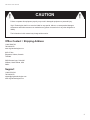
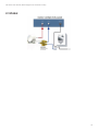
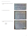
July 2013
VR SERIES USER MANUAL
VR Series User Manual
TABLE OF CONTENTS
1
2
3
4
5
6
7
Introduction
1.1 About this manual…............................................
4
4
Block Diagrams for Hardware Hookup
2.1 iDirect Evolution…...............................................
2.2 Direcway 7700…................................................
2.3 ViaSat…..............................................................
5
5
5
6
Initial Controller Setup, From Factory Reset
3.1 Quick Setup….....................................................
3.2 Network Setup….................................................
7
7
13
Manual Setup and Detailed Options
4.1 Main Menu (one-button deploy)…......................
4.2 Main Menu…......................................................
4.2.1 Automatic….........................................
4.2.2 Manual….............................................
4.3 Admin Menu…....................................................
4.3.1 Mount Options….................................
4.3.2 Satellite Options…..............................
4.3.3 Modem Options…...............................
4.3.4 Controller Options…...........................
4.3.5 About…...............................................
16
16
16
17
17
18
19
20
22
23
25
Deployment
5.1 Deployment Methods…......................................
5.1.1 One-Button Deploy…..........................
5.1.2 Automatic….........................................
5.1.3 Manual….............................................
5.2 Lock On…...........................................................
26
26
26
27
28
29
Troubleshooting
6.1 Diagnose Screen…............................................
6.2 Motor Stopped Menu…......................................
6.3 Calibration….......................................................
30
30
31
32
Contact / Support
35
2
VR Series User Manual
CAUTION
Failure to operate this equipment properly may result in damaged equipment or personal injury.
Virgin Technologies shall in no event be liable for any special, indirect, or consequential damages
whatsoever and neither assumes nor authorizes any person to assume for it any other obligation or
liability.
The information in this manual may change without notice.
Office Contact / Shipping Address
1-866-788-8728
780-469-4470
www.virgintechnologies.com
9333-37 Ave
Edmonton, Alberta, Canada
T6E 5N4
5056 Bennett Loop, Suite 400
Williston, North Dakota, USA
58801
Support
1-866-875-2523
780-469-4470
[email protected]
www.virgintechnologies.com
3
VR Series User Manual | Introduction
1
INTRODUCTION
1.1 About this Manual
This guide details the preparation and use of the VR Series
Controller with the VR7 series satellite mount.
4
VR Series User Manual | Block Diagrams for Hardware Hookup
2
BLOCK DIAGRAMS FOR HARDWARE HOOKUP
2.1 iDirect Evolution
2.2 Direcway 7700
5
VR Series User Manual | Block Diagrams for Hardware Hookup
2.3 ViaSat
6
VR Series User Manual | Initial controller set up
3
INITIAL CONTROLLER SET UP
FROM FACTORY RESET
3.1 Quick Setup
If this is the first time the controller has been setup, or if
a factory reset has been done, use the following guide to
initially setup the VR controller for use.
NOTE:
Ensure the modem and router being used are both
configured correctly before setting up the VR Controller.
Quick Setup Steps:
1. Connect all of the power, network, signal connections
as per the diagram.
A
Information Screen
B
Quick Setup Screen
2. Power on the controller, you will see the Information
Screen before it changes to the Quick Setup Screen.
When ready to continue with the setup, press where it
says “Press Here to Continue”. A B
7
VR Series User Manual | Initial controller set up
3. Adjust the Screen Contrast to for best viewing, and
save. C
4. Select the Mount Type, and save. D
C
Contrast Screen
D
Mount Type Screen
E
Reflector Size Screen
5. Select the Reflector Size and press RET to continue,
press: E
1 for 1.2m
2 for .98m
4 for 1.8m
8
VR Series User Manual | Initial controller set up
6. Select if the mount has a rising platform and press RET
to continue, press: F
1 for ON
2 for OFF
F
Rising Platform Screen
G
Dominate Satellite Screen
H
Target Satellite
7. Enter the degrees of the dominant satellite and press
RET to continue. G
•
Example: G16 is at 100.8°or SatMex 8 is at 117°
8. Enter the degrees of the target satellite and press RET
to continue. H
•
Example: G16 is at 99° or SatMex 8 is at 116.8°
9
VR Series User Manual | Initial controller set up
9. Enter the hemisphere and press RET to continue: I
1 for East
2 for West
I
Hemisphere Screen
J
Rx Polarity Screen
K
Modem Type Screen
10. Enter the RX polarity and press RET to continue, press:
J
1 for Vertical
2 for Horizontal
• Example: G16 is V or SatMex 8 is H
11. Select the modem type. K
12. Select the GPS Setup (Default is Mobile) and save. K
10
VR Series User Manual | Initial controller set up
13. Select the TX enable pin and press RET to continue,
press: L
1 for HIGH
2 for LOW
• Default is 2 (LOW)
L
TX Enable Pin Screen
M
Modem IP Address Screen
N
Setup Results Screen
14. Input the modem IP address and press RET to
continue. M
•
Ensure the ‘.’ are input as well, for example enter
“192.168.1.1”. This is the accessible address of
the modem
15. Review the data input and ensure it is correct. If
correct SAVE, if not, press Start Over to begin again. N
11
VR Series User Manual | Initial controller set up
16. The quick setup is now complete. The modem
password and network address should now be set.
When entered, press SAVE to continue. O
•
By default the controller is set to DHCP, however if
your specific network requires the controller to be
on a static IP, it can be entered now.
•
If your specific modem requires a password, it can
be entered now
O
Quick Setup Complete Screen
P
Calibrate Screen
17. The mount must now be calibrated. See detailed
information on calibration under Troubleshooting
section. P
12
VR Series User Manual | Initial controller set up
3.2 Network Setup
By default the VR controller is set for DHCP and will
automatically obtain network address information when
connected to a router. However, if the network information
needs to be viewed or you require the controller to have a
static IP, complete the following steps below.
The most ideal network setup is to have the controller
connect to the modem through a DHCP enabled Router
with the modem connected to the Router’s WAN port.
Alternatively, a direct connection to the modem via a
crossover cable using Static IP Addresses will work as well.
On startup, the controller will check for a proper Ethernet
connection an attempt to set its network IP address if a
network is detected. For a DHCP setup, the controller will
attempt to locate the networks DHCP server and request
an IP. For Static IP, the controller will configure itself with
the Static IP Address saved in flash memory. Should the
controller be disconnected from the network, the Network
initialization will fail and no IP address will be set.
Depending on the modem being used, the Modem’s IP
Address may have to be set before the controller can
communicate with the modem. Currently the Advantech
Modem and the iDirect Modem (Ethernet mode) require
an IP Address to be set (DirecWay uses a fixed value that
doesn’t change). The Modem IP Address can be changed
at any time from the Admin Modem Menu (see above).
Network Setup Steps:
1. From the main menu, press the ADMIN MENU button
A
A
Main Menu Screen
13
VR Series User Manual | Initial controller set up
2. Enter the admin Password and press RET to continue.
B
B
Enter Admin Password Screen
C
Admin Menu Screen
D
Admin Modem Screen
3. From the admin menu press the Modem Options. C
4. In the Admin Modem screen, press the Network Setup.
D
14
VR Series User Manual | Initial controller set up
5. The controller is by default setup for DHCP. It will
acquire its network information from your router
automatically. E
Static IP Setup: This will load the Network Setup menu.
Here the controller can be set to Static IP mode and
the Static Addresses can be set. There are 5 Static Address
that can be configured (IP, Subnet, Gateway, and 2
optional DNS Addresses). Pressing the Back button will
automatically attempt to renew the IP Address (see below).
Renew IP Address: Causes the Controller to try to renew
its IP Address. As with the startup routine, the controller will
check for a DHCP server for DHCP mode, or it’ll load the
Static IP addresses for Static IP mode.
E
Network Setup Screen
Remote Access Menu (Remote Access build only):
Loads the Remote Access Menu. The Remote Access
password is required to proceed.
Return to Admin Menu: Exits the Network Setup Menu.
15
VR Series User Manual | Manual Setup and Detailed Options
4
MANUAL SETUP AND DETAILED OPTIONS
4.1 Main Menu (One-Button Deploy)
After turning the power on to the controller, if the PowerOn Self Test finishes with no critical issues, the “One
Button Deploy” Menu will load. If critical startup issues are
detected, this menu will be skipped and the Main Menu will
load instead. The “One Button Deploy” menu features 2
buttons: Find Satellite, and Main Menu. A
Find Satellite: Deploys the dish using Elevation
Inclinometer and GPS Coordinates.
Main Menu: Loads the Main Menu.
A
One-Button Deploy Screen
B
Main Menu Screen
4.2 Main Menu
This is the Main Menu for the controller. All of the software
functionality is accessible from here. The Main Menu
features four buttons: Automatic, Manual, Stow Dish, and
Admin Menu. B
Automatic: Starts the dish deployment routine. See the
Quick Deploy Menu below for user options and system
checks. Pressing Automatic while the dish is stowed will
reset the counters.
Manual: Loads the Manual Controls for dish movement.
See the Manual Menu for full instructions. Make sure that
you have a visual of the mount to avoid any collisions while
the mount is moving.
Stow Dish: Starts the Stow Dish routine. The controller
will begin by moving the Elevation to 90 degrees, then
move the Azimuth to stow position, then move the
Crosspole to stow position (either the centre position
or on a limit, depending on the configuration), and then
move the Elevation to stow position. Any motor errors will
automatically pause the routine (see Motor Stopped Menu
below). For the Platform configuration, the Platform will
lower after the Crosspole is moved into Stow position.
16
VR Series User Manual | Manual Setup and Detailed Options
Admin Menu: Loads the Admin Menu. The Admin
Password must be entered in order to proceed. See the
Admin Menu below for more information.
4.2.1 Automatic
See the Deployment section below.
4.2.2 Manual
This screen allows the user to manually move the mount
around. This can be used to: Manually site the mount in for
pointing, Move the mount for maintenance or calibration,
Testing, or Storage.
The TX Disable command will be set to the modem when
this menu loads.
NOTE
That there are no motor safeties while in manual mode, so
the user should exercise caution to prevent damage to the
mount or any surrounding objects.
C
Manual Screen
D
VR Controller Buttons
The screen is divided into 4 sections; Azimuth, Elevation,
Crosspole, and the Analog Signal Strength. Each has a
graph illustrating the axis’s position and the signal strength,
as well as a numerical value for each. The Platform will
appear below the Signal Strength as a percentile if it’s
toggled on. On the controller’s keypad, the Up and Down
arrows move the Elevation, the Left and Right arrows
move the Azimuth, the two buttons on either side of the Up
arrow move the Crosspole (left button moves CCW and
right button moves CW), and the two outer buttons drive
the Platform up (left button) and down (right button). Press
and hold a direction button to move the corresponding
axis, and press and release to nudge the axis for precision
movement. C D
Read GPS: Gets the GPS coordinates for the current
location. The results are displayed on the screen along with
the Elevation and Crosspole deploy angles for the satellite
for your current location. The GPS will be re-initialized if the
module wasn’t detected at startup.
17
VR Series User Manual | Manual Setup and Detailed Options
Verify: Checks the modem for an RX Lock; used if the
user was successful in finding the satellite manually or if
the mount was already deployed. The user will have to
option of using the GPS module or entering the coordinates
manually (see Quick Deploy Menu above). If an RX Lock is
confirmed, the Deployed Menu will load and the user can
then repeak the satellite as normal (see Deployed Menu
below).
Back: Returns to the previous menu screen.
4.3 Admin Menu
The Admin Menu is where all of the software setting can be
checked and modified. The Admin Password is required to
access the Admin Menu. The contents of the sub-menus
in the Admin Menu can change depending on the modem
used and any other software features that are loaded. E
NOTE
That once the calibration routine has been completed,
certain mount related settings (Mount Type and n Mount
Settings) will be considered locked in and unchangeable.
Should the user attempt to change any of the above listed
settings, a large message will be displayed, warning the
user that changing the setting will undo the calibration. The
user will have the option to cancel the change and leave
the settings alone. Should the user confirm the change, the
controller will become flagged as not calibrated, requiring
the user to redo the calibration with the new settings. This
warning will not present itself while the controller is flagged
as not calibrated (such as right after a factory reset).
Mount Options: Settings pertaining to the VR mount
Satellite Options: Settings pertaining to the spacecraft target
Modem Options: Settings pertaining to the modem
Controller Options: Settings pertaining to the VR
controller
About: General information
Main Menu: Back to the Main Menu
Diagnose: Troubleshooting options, see the section below
on troubleshooting
E
Admin Menu Screen
18
VR Series User Manual | Manual Setup and Detailed Options
4.3.1 Mount Options
This sub-menu contains options related to the physical
mount. Crosspole options are located under the Satellite
Options menu. F
F
Mount Options Screen
G
Calibrate Screen
H
Mount Type Screen
Routine Calibration: Loads the Dish Calibration routine.
Instructions for setting up the mount for your hardware
configuration will be listed as well as a link to the Manual
Menu to move the mount into position. See detailed
information on calibration under Troubleshooting section. G
Mount Type: Selects which Mount Revision is attached
to the controller. All of the supported mount types are
presented as individual touch screen buttons. Once the
mount type is selected, press the Save Settings and Exit
button below to return to the Admin Mount Menu. Only a
different and valid mount selection is saved. Pressing the
Save button without selecting a Mount Type is treated as
canceling out of the menu (no changes will be saved).
Changing this setting after Calibration will undo the
controller’s calibration. H
19
VR Series User Manual | Manual Setup and Detailed Options
Mount Settings: Sets the various sub-options available
for your mount. Some of the options presented here are
not available to older mounts and certain combinations,
and will not be displayed (appropriate default values will be
loaded automatically). The first option will be the Elevation
Inclinometer Type (SEIKA or i100), then the Reflector Size
(1.2m, 0.98m, or 1.8m), then the Rising Platform toggle
(ON or OFF) and the Rising Platform Configuration (Single
Motor or Dual Motor) (VR8 Only). Changes here after
Calibration will undo the controller’s calibration. I
I
Reflector Size Screen
J
Motor Stall Thresholds Screen
K
Satellite Options Menu Screen
Motor Stall Thresholds: Sets the error buffer percentile
for the Motor Stall Safeties for each of the available motors.
Higher percentile values will loosen the buffer, requiring
greater force to stall the motors. Lower percentile values
will tighten up the buffer, increasing the sensitivity but could
cause the controller to flag false errors. It’s recommended
to leave this setting at its default value. J
4.3.2 Satellite Options
This sub-menu contains options related to the Satellite and
the Crosspole. K
20
VR Series User Manual | Manual Setup and Detailed Options
Change Satellite: Sets the Satellite longitude that the
controller will search for. Settings include Dominant
Satellite (same as Target Satellite unless a Satellite Offset
is required), Target Satellite (the satellite you want to
connect to), and the Satellite Hemisphere (East or West).
LM
L
Dominate Satellite Screen
M
Target Satellite Screen
N
Rx Polarity Screen
Receive Polarity: Sets the Crosspole’s Rx Polarity
(Vertical or Horizontal). Note that changing the Crosspole
Polarity will not affect your calibration, although physically
changing the Crosspole Basket for non-extended range
Crosspoles (older models) may be required. N
21
VR Series User Manual | Manual Setup and Detailed Options
Satellite Wait Delay: Sets the time in seconds that the
controller will wait for an RX Lock during the satellite
search. O
O
Satellite Wait Delay Screen
P
Deploy Offset Screen
Q
Admin Modem Screen
Deploy Offset: Toggles the Deploy Offset mode (Auto
or Manual). Automatic Deploy Offset script is enabled
by default. This will automatically apply an appropriate
Dish Offset Degree value to memory if the satellite was
found on anything other then the first forward pass. The
Deploy Screen will list an ‘Applied’ message next to the
pass number when a modification was made. This will
only occur on a fresh deploy. Repeak, Manual Verification,
NOC Tuning Re-Verification and Startup Verification will
not modify the shared offset value. When deploying without
the Elevation Inclinometer (full sweep search), the Deploy
Offset value is no longer applied to the search routine P
4.3.3 Modem Options
This sub-menu contains options related to the modem and
networking. Modem specific options will not be available
unless that modem build is loaded in software. Q
22
VR Series User Manual | Manual Setup and Detailed Options
Network Setup: Loads the Network Setup menu for your
particular modem and features. See Network Information
Menu below for network configuration and other options. R
Signal Thresholds: Sets the Signal Threshold (analog
voltage threshold value for satellite peaking), and the
Digital Fine-Tuning toggle (ON or OFF). S
Advantech Setup: Set the IP Address for the Advantech
Modem
DirecWay Overrides: Set the DirecWay settings (Symbol
Rate and Frequency). Automatic mode (default) will
request the Symbol Rate and Frequency from the modem
each time the values are needed. Otherwise, enter a valid
override value at the prompt (ksps for Symbol Rate and
MHz for Frequency)
R
Network Setup Screen
S
Signal Thresholds Screen
T
Controller Option Screen
iDirect Setup: Set the iDirect Modem series for the
controller (iDirect Modem (iNFINITI), iDirect Evolution,
or iDirect NetModem II+) and the Modem’s GPS Setup
(Mobile or Static). Unless the Rising Platform mount has
been selected, the TX Enable Pin (HIGH or LOW) needs
to be set as well. For modems with Ethernet connections,
the Modem IP Address needs to be set for proper modem
connection
ViaSat Linkstar Setup: Set the ViaSat Linkstar series for
the controller (ViaSat Linkstar S1 or ViaSat Linkstar S2)
Modem Password (iDirect and ViaSat Linkstar only):
Set the password needed to communicate with the modem.
If the modem has a blank password (no password), enter
the phrase <blank> with the brackets to register a blank
password
4.3.4 Controller Options
This sub-menu contains options related to the controller. T
23
VR Series User Manual | Manual Setup and Detailed Options
Calibrate Touchscreen: Calibrates the Touchscreen
range and sensitivity. Instructions on where to touch will
be displayed at each stage of the routine. This calibration
routine is recommended only if issues with the touchscreen
arise. U
U
Calibrate Touchscreen Screen
V
Controller Setup Screen
W
Contrast Screen
Controller Setup: Set the controller to either Solid State or
Relay for the motor drivers, and the Error Buzzer toggle on
or off. V
Screen Contrast: Set the Screen Contrast. Use either the
onscreen buttons, or the left and right arrow buttons on the
keypad to adjust the contrast value. W
24
VR Series User Manual | Manual Setup and Detailed Options
Admin Password: Change the Admin Password. X
X
Admin Password Screen
Y
About Screen
4.3.5 About
This sub-menu contains options related to the controller. Y
25
VR Series User Manual | Deployment
5
DEPLOYMENT
5.1 Deployment Methods
5.1.1 One-Button Deploy
After turning the power on to the controller, if the PowerOn Self Test finishes with no critical issues, the “One
Button Deploy” Menu will load. If critical startup issues are
detected, this menu will be skipped and the Main Menu will
load instead. The “One Button Deploy” menu features 2
buttons: Find Satellite, and Main Menu. A B
Find Satellite: Deploys the dish using Elevation
Inclinometer and GPS Coordinates.
A
One-Button Deploy Screen
B
Searching Screen
26
VR Series User Manual | Deployment
5.1.2 Automatic
Automatic can be selected from the main menu.
Before the dish deploys, the controller will check to see
if the dish is in the stow position and will call the Stow
Dish routine (see above). Once the mount is stowed, the
controller will reset the counters to zero. C D
The Quick Deploy Menu features five buttons: Use GPS
Coordinates, Enter Manual Coordinates, Disable the
Inclinometer (GPS Coordinates), Disable the Inclinometer
(Manual), and Return to Previous Menu.
Use GPS Coordinates: This will use the attached GPS
Module to acquire the GPS coordinates. If the GPS
Module failed on startup, the controller will attempt to reinitialize the GPS Module, then attempt to read the GPS
coordinates. Elevation Self-Leveling will be enabled during
the satellite search.
C
Deploy Options Menu Screen
D
Searching Screen
Enter Manual Coordinates: This will prompt the user for
the GPS coordinates (latitude, longitude, and hemisphere).
When prompted, enter the coordinates in decimal format.
Elevation Self-Leveling will be enabled during the satellite
search.
Disable the Inclinometer (GPS Coordinates): Same as
the Use GPS Coordinates option, except that the Elevation
Self-Leveling will be disabled during the satellite search.
Disable the Inclinometer (Manual): Same as the Enter
Manual Coordinates option, except that the Elevation SelfLeveling will be disabled during the satellite search.
Before the GPS coordinates are checked, the controller
will perform another system check. Calibration Status,
applicable Inclinometers, and modem communication
will be verified. Any problems will be displayed on the
screen along with a prompt for the user to either continue
the deployment or abort. For deploy options that utilize
Elevation Self-Leveling, if the elevation Inclinometer fails
its test, the controller will switch the Elevation Self-Leveling
feature off during the satellite search.
27
VR Series User Manual | Deployment
5.1.3 Manual
This screen allows the user to manually move the mount
around. This can be used to: Manually site the mount in for
pointing, Move the mount for maintenance or calibration,
Testing, or Storage. The TX Disable command will be sent
to the modem when this menu loads.
NOTE:
That there are no motor safeties while in manual mode, so
the user should exercise caution to prevent damage to the
mount or any surrounding objects.
The screen is divided into four sections; Azimuth, Elevation,
Crosspole, and the Analog Signal Strength. Each has a
graph illustrating the axis’s position and the signal strength,
as well as a numerical value for each. The Platform will
appear below the Signal Strength as a percentile if it’s
toggled on. On the controller’s keypad, the Up and Down
arrows move the Elevation, the Left and Right arrows
move the Azimuth, the 2 buttons on either side of the Up
arrow move the Crosspole (left button moves CCW and
right button moves CW), and the 2 outer buttons drive the
Platform up (left button) and down (right button). Press
and hold a direction button to move the corresponding
axis, and press and release to nudge the axis for precision
movement. E F
Read GPS: Gets the GPS coordinates for the current
location. The results are displayed on the screen along with
the Elevation and Crosspole deploy angles for the satellite
for your current location. The GPS will be re-initialized if the
module wasn’t detected at startup.
E
Manual Screen
F
VR Controller Buttons
Verify: Checks the modem for an RX Lock; used if the
user was successful in finding the satellite manually or if
the mount was already deployed. The user will have to
option of using the GPS module or entering the coordinates
manually (see Quick Deploy Menu above). If an RX Lock is
confirmed, the Deployed Menu will load and the user can
then repeak the satellite as normal (see Deployed Menu
below).
Back: Returns to the previous menu screen.
28
VR Series User Manual | Deployment
5.2 Lock On
Once an RX Lock is confirmed and the mount is finished its
digital peaking routine (Fine-Tuning and Crosspole peaking
if applicable), the Mount Deployed Menu will load. Verifying
the satellite from the Manual Menu will also load this
menu, skipping the digital peaking. The GPS Latitude and
Longitude, current modem Signal Strength, and which pass
number the satellite was found on will be displayed at the
bottom of the screen. The Signal Strength value will refresh
automatically at regular intervals (30 seconds for Ethernet
modems, 60 seconds or serial). This menu features 4
buttons: Repeak Satellite, Stow the Mount, Refresh SNR,
and NOC Tuning. G
Repeak Satellite: This will cause the mount to move off
the satellite and attempt to re-acquire an RX Lock. First the
TX Disable command will be sent to the modem, then the
mount will move a few degrees away from the satellite, and
the satellite search will begin anew. Use this if the satellite
signal has weakened and needs to be corrected.
G
Mount Deployed Screen
Stow the Dish: Calls the Stow Dish Routine (see above).
The TX Disable command will be sent first.
Refresh SNR: Request a new SNR value from the modem.
Note that the buttons will disappear while the controller
waits for the new SNR value. Either the current SNR value
will be displayed, an offsignal message, or a relevant error
message should a modem communication issue arise.
NOC Tuning: Loads the Manual Menu (NOC Tuning). The
Admin Password is required to proceed. Note that TX will
remain ON while the NOC Tuning controls are loaded.
29
VR Series User Manual | Troubleshooting
6
TROUBLESHOOTING
6.1 Diagnose Screen
This sub-menu contains various tools useful for diagnosing
problems with the mount, controller, and modem. A
A
Diagnose Screen
B
Motor Count Loss Screen
C
Test Modem Connection Screen
Motor Count Loss Test: This test will perform a quick
nudging test with all three motors to check for any count
loss. Since the mount will be moving, please make sure
that you have enough space around the mount before
starting the test. Once the test is finished and the mount
has returned to its stow position, the results will be
displayed onscreen. B
Test Modem Connection: This test is the same as the
modem test performed prior to deployment. The controller
will request an SNR value from the modem and will display
the result (either a pass or the specific error that was
encountered). C
30
VR Series User Manual | Troubleshooting
6.2 Motor Stopped Menu
This menu screen will load if the current mount movement
has stopped. This will happen if there was a motor error
or the user paused the action by pressing a keypad button
while the mount was moving. The axis that was moving
last will be displayed, along with a brief description of the
condition that caused to motor to stop. The Motor Stopped
Menu features three buttons: Resume, Stow, and Manual
Controls. Additional buttons may appear under unique
circumstances (see below). D
Resume: This will resume the last move action. If the
Motor Stopped Menu reloads after resuming, then there
probably is a problem with the mount.
Stow: This will call the Stow Mount Routine, aborting the
previous move action. Pausing the satellite search and
pressing Stow is an ideal means to stop the search. If
the mount was stopped in the middle of the Stow Mount
Routine, the routine will restart from the beginning. See
“Stow Mount” under the Main Menu portion of this manual
for a full description of the stow routine.
D
Motor Stopped Screen
Manual Controls: This will load the Manual Menu (see
above).
NOTE:
That pressing the Back button in the Manual Menu will not
return to the Motor Stopped Menu, but instead return to the
Main Menu. Cold Temperature Override: Cold temperatures
outside (-20c or lower) can cause the motors to move much
slower, triggering Motor Stall errors needlessly. Should this
occur repeatedly, a fourth button will appear at the bottom
of the screen allowing the user to toggle the Extreme Cold
Override on for the remainder of the software session.
Toggling this on will temporarily disable the Motor Stall
Safeties, allowing the mount to move in the cold.
31
VR Series User Manual | Troubleshooting
6.3 Calibration
Please read these instructions thoroughly prior to running
the calibration routine.
To begin the Mount Calibration Routine, go to the
Calibration Screen in the Admin Menu (Main Menu
-->Admin Menu-> Mount Options-> Calibration Routine).
There you’ll see brief instruction on setting up your mount
along with 3 buttons: Calibrate, Back, and Manual Control.
Calibrate: Once the dish is leveled and ready, press this
button to begin the calibration routine. It is recommended
that the user observe the mounts movements during the
calibration routine.
Back: Returns to Admin Mount Menu
E
Calibrate Screen
F
Level the Base
Manual Controls: Loads the Manual Menu (see above).
Use this to move the dish into position for calibration (see
below). Note that the Read GPS and Verify buttons will not
be available at this stage. E F
The three steps needed for calibration are as follow: level
the base of the mount, level the back of the dish to 90
degrees, and level the crosspole at its center position
(either Horizontally or Vertically, depending on the setup).
The Platform needs to be raised as well (if applicable).
Level the Base: Start by moving the elevation up to
approximately 90 degrees. Then place a level on the base
of the mount so that the ends of the level are pointing to the
front and back of the mount.
NOTE:
That the side with the Crosspole arm is the front of the
mount. Prop up either end until the base is level. Repeat
for both sides of the mount. Leveling the other orientation
(level is pointing to the left and right side of the mount) isn’t
required for calibration. F
Raise the Platform (Platform Mount Only): The Platform
needs to be all the way to the top for the Calibration
Routine. Once the Platform is up, double-check the levels
for the Base.
Level the Dish to 90 Degrees: Once the base is level,
32
VR Series User Manual | Troubleshooting
place the level on the back of the mount inline with the
reflector and move the elevation until it is level. On the back
of the mount where the frame is attached to the reflector,
there is a flat spot (usually between the two screws that
mounts the reflector in place) that can be used to level
the elevation. Elevation nudging (pressing and releasing
the move button on the controller quickly) can be used for
precise elevation movement. G
Level the Crosspole: Once the base and the elevation are
leveled, move the crosspole so that its physical orientation
matches its configuration (Horizontal or Vertical). For
mounts with the extended range reed-counter crosspole,
treat the mount as Horizontal regardless of the polarization
setting in the controller. Use crosspole nudging to get the
crosspole as close to center as possible. Use can use the
crosspole basket (particularly the front cover with the yellow
warning sticker) as a guide to balance the crosspole. H
Once the mount is ready, press Back to return to the
Calibration Screen and press Calibrate to begin. It is
recommended that the user watch the mount during
the Calibration Routine in case of clearance issues or
a problem occurs. It’s important that the mount remain
balanced and level throughout the routine. The Calibration
Routine can be paused at any time be pressing any key on
the keypad (see Motor Stopped Menu below). Any issues
detected during the Calibration Routine will cause the
process to abort.
First the Crosspole will be moved CW, then CCW, then
moved to Stow position (center for Horizontal and CW to
the Upper Limit for Vertical). The orientation is based on
facing the crosspole with the reflector in the background.
Next the azimuth will attempt to move CW to Stow in case
it wasn’t there already. Next the Elevation will move all the
way down (stow position), then all the way up to the upper
limit. Next the Azimuth will move CCW to the upper limit
(approximately 370 degrees), and then rotate back to Stow
position. Next the Stow Routine will call. For Mounts with
Elevation Drive-Arms (VR7 and earlier), the Elevation will
move to the Pre-Load angle, followed by another call to the
Stow Dish Routine.
G
Level the Dish to 90 Degrees
H
Level the Crosspole
If the Platform is toggled on, the Platform will attempt to rise
to the top in case it wasn’t there already before the Azimuth
stow test is performed, then it will lower all the way down
before the Elevation lowers to the stow position. For Single
Motor Platforms (VR9 Mounts), the Platform will then rise to
its upper limit before the Elevation moves at all. Otherwise,
33
VR Series User Manual | Troubleshooting
the Elevation will lower to stow position, then rise to 90
degrees before the Platform will raise all the way to the top,
then the Elevation will continue on up.
After the Dish Calibration Routine is done, the dish is ready
to deploy. The calibration results can always be reviewed
on the third page of Current Values (Main Menu-> Admin
Menu-> Current Values).
34
VR Series User Manual | Contact / Support
7
CONTACT / SUPPORT
Office Contact / Shipping Address
1-866-788-8728
780-469-4470
www.virgintechnologies.com
9333-37 Ave
Edmonton, Alberta, Canada
T6E 5N4
5056 Bennett Loop, Suite 400
Williston, North Dakota, USA
58801
Support
1-866-875-2523
780-469-4470
[email protected]
www.virgintechnologies.com
35