1
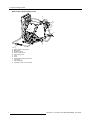
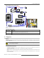
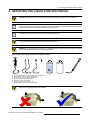
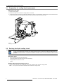
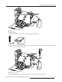
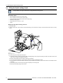
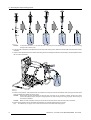
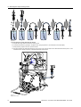
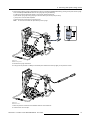
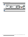
Cooling liquid refurbishment
Installation manual
For XLM, DP90 and DP100
R59770032/01
07/12/2006
Barco nv Events
Noordlaan 5, B-8520 Kuurne
Phone: +32 56.36.89.70
Fax: +32 56.36.88.24
E-mail: [email protected]
Visit us at the web: www.barco.com
Printed in Belgium
1. Liquid Cooling Circuit
1. LIQUID COOLING CIRCUIT
Overview
•
Safety
•
Introduction
•
Diagnostics
1.1
Safety
WARNING: Hazardous product:
Blue antifreeze diluted 1,2 ethanediol (1/3 ethanediol – 2/3 Demi water).
Not for household use. Keep out of reach of children. Harmful by oral intake. Avoid exposure to pregnant
women. Avoid contact with eyes, skin and clothing. Avoid inhale of the noxious fumes.
Handling the cooling liquid
•
Avoid contact of the liquid with Eyes, Skin and Clothing.
•
Avoid inhaling of the noxious fumes.
•
Conserve the product in the original package and in a well ventilated room.
Personal protection rules
1.2
•
Handle the cooling liquid in a well ventilated room.
•
Under no circumstances eat, drink and smoke while handling the liquid.
•
Wear gloves (Butylrubber, PVC....) and Goggles.
•
Wear suitable protection clothing.
Introduction
Functionality
Much heat has to be extracted from the DMD’s and from the light pipe entrance during operation of the projector. The liquid cooling
circuit takes care of this. The liquid cooling circuit is a closed loop of flexible tubing comprising of a pump, three cooling blocks for
the DMD’s, a cooling block for the light pipe entrance, a heat exchanger, a pressure vessel and a manometer. The cooling liquid
inside the circuit absorbs the heat of the cooling blocks. Via the pump, the heated-up liquid is transported to the heat exchanger,
which in turn cools down the liquid.
The pressure vessel in the circuit makes it possible to put a small pressure on the cooling liquid. The required pressure exerted via
the pressure vessel serves to prevent cavitation and hence ensures the good working condition of the pump. Note that the pressure
doesn’t influence the cooling capacity of the system.
R59770032 COOLING LIQUID REFURBISHMENT 07/12/2006
1
1. Liquid Cooling Circuit
Parts of the liquid cooling circuit
K
B
J
C
D
E
F
A
G
H
I
Image 1-1
A
B
C
D
E
F
G
H
I
J
H
2
DMD - Peltier cooling block.
Manometer.
Pressure vessel.
Outlet cooling circuit
Inlet cooling circuit
Vane
Pump.
Cooling block light pipe entrance.
Flow switch.
Heat exchanger.
Transparent tube for visual check.
R59770032 COOLING LIQUID REFURBISHMENT 07/12/2006
1. Liquid Cooling Circuit
Block diagram of the cooling circuit
Pressure relief
valve (3 Bar)
Outlet
Manometer
Vane
Heat
Exchanger
Inlet
Expansion Vat
Pump
Engine
Light Pipe
entry
Outlet
Inlet
Vane
Waterflow Sensor
to SMPS Control
Image 1-2
Block diagram cooling circuit
Order info liquid cooling
1.3
Order number
Description
R395198K
Complete liquid cooling refill kit. Includes tubes, valved fittings, syringe, air pump, plastic bottle of 1 liter
filled with cooling liquid and one empty plastic bottle of 1 liter.
B1909086K
Two bottles of 1 liter filled with cooling liquid. (no additional tools)
Diagnostics
General
Over extended periods there may be small losses of pressure in the liquid cooling system of the projector. It is therefor recommended
to check the pressure at regular intervals. In case the pressure drops below 0,5 bar it is recommended to restore the pressure of
the liquid cooling system.
CAUTION: In case of a rapid loss in pressure check the liquid cooling circuit for leakage. Solve the problem
before starting up the projector.
Troubleshooting cooling loop
•
Any significant or rapid drop in pressure indicates a leakage of liquid. If this be the case, verify whether the circuit shows any
visible sign of liquid leakage.
•
As critical components rely on this liquid cooling, it is essential that any leakage is detected timely.
•
Periodic checking of the liquid cooling pressure is essential to guarantee overall good performance of the projector and the
pump.
•
The factory pressure preset is approximately 1 bar in the ’Projector Off’ status at a room temperature of 25 °C. This may drop
slightly during operation.
R59770032 COOLING LIQUID REFURBISHMENT 07/12/2006
3
1. Liquid Cooling Circuit
Too high ambient temperature
An Error or warning message “Ambient temp high” is displayed on the local LCD panel or touch panel. See manual of the projector
for accessing error messages.
Possible cause
Solution
Ambient temperature of the projector is too high.
Measure the ambient temperature nearby the projector. In
case the measured temperature is higher than 40 °C take
the necessary measurements to ensure that the ambient
temperature is below 40 °C.
Blocked filter at the front side and the left side of the projector
Clean the blocked filter.
One of the DMD’s is too high in temperature
An Error or warning message “DMD temp high” is displayed on the local LCD panel or touch panel. See manual of the projector for
accessing error messages.
Possible cause
Solution
Malfunction Peltier element of the involved DMD. Only one
DMD is too high in temperature while the other two DMD’s
have a normal and almost equal temperature.
1.
Check if the wire unit of the involved Peltier is connected
with the interface board.
2.
Check if the wire unit of the temperature sensor (NTC) is
connected with the interface board.
3.
Check the fan control board. In case of malfunctioning
replace the board.
4.
Defect Peltier element. Replace Peltier.
The wire units of two Peltier elements or there respective
temperature sensors (NTC’s) have been swapped. While the
temperature of one DMD is too high, the other will most likely
be to low.
Check if the wire units of all Peltiers and all temperature
sensors (NTC’s) are plugged in there respective connector
sockets on the interface board.
Poor assembly of DMD or Peltier + cooler block.
Reinstall the Peltier.
All DMD’s are too high in temperature
An Error or warning message “DMD temp high” is displayed on the local LCD panel.
Possible cause
Solution
The liquid cooling circuit of the light processor is mistakenly
excluded from the main liquid cooling circuit.
Check of the cooling circuit of the light processor is connected
with the pump and heat exchanger.
None of the wire units of the Peltier elements or there
respective temperature sensors (NTC’s) are connected.
Check if the wire units of all Peltiers and all temperature
sensors (NTC’s) are plugged in there respective connector
sockets on the interface board.
Blocked filter of the heat exchanger.
Clean the blocked filter.
No flow of the cooling liquid
An Error message “Water flow” is displayed on the local LCD panel.
4
Possible cause
Solution
Interruption of the liquid cooling circuit.
Check if the loop of the liquid cooling circuit is closed.
No or insufficient liquid inside the cooling circuit. The pump is
sucking air and sounds noisier then normal.
Fill the cooling circuit with liquid and expel all air. Pressurize
the circuit.
R59770032 COOLING LIQUID REFURBISHMENT 07/12/2006
1. Liquid Cooling Circuit
Possible cause
Solution
Defect pump. When the projector is running, you don’t feel
any vibrations when touching the pump
Drain the liquid cooling circuit, replace the pump, fill and
pressurize the liquid cooling circuit.
Tip: It’s not necessary to drain the cooling circuit of the light
processor. Bypass this part of the cooling circuit.
Defect flow switch. The pump is functioning normally but the
projector displays a water flow error.
Drain the liquid cooling circuit, replace the flow switch, fill and
pressurize the liquid cooling circuit.
Tip: It’s not necessary to drain the cooling circuit of the light
processor. Bypass this part of the cooling circuit.
R59770032 COOLING LIQUID REFURBISHMENT 07/12/2006
5
1. Liquid Cooling Circuit
6
R59770032 COOLING LIQUID REFURBISHMENT 07/12/2006
2. Servicing the liquid cooling circuit
2. SERVICING THE LIQUID COOLING CIRCUIT
WARNING: All procedures in this chapter may only be performed by “qualified service technicians” .
Definition of “qualified service technicians” or ”qualified technicians”: Persons having appropriate technical
training and experience necessary to be aware of hazards to which they are exposed in performing a task and
of measures to minimize the danger to themselves or other persons.
All procedures in this chapter require the removal of the side cover of the projector. See user manual of the
projector for instructions on how to remove and install the side cover.
WARNING: All actions performed on the liquid cooling circuit should occur in ambient conditions (25°).
The
projector should have sufficiently cooled down (minimum 2 hours).
WARNING:
Do not change the air pressure of a calibrated liquid cooling circuit (see marking on pressure
vessel), unless stated explicitly in the servicing procedure.
Tools used in the liquid cooling servicing procedures
A
B
60
60
cm
60
cm
C
60
D
E
F
G
cm
1L
cm
Image 2-1
A
B
C
D
E
F
G
Syringe with plastic tube (60 cm) and male valved fitting.
60 cm plastic tube with male valved fitting.
60 cm plastic tube with female valved fitting.
Female/female valved fitting adaptor.
Bottle with 1 liter cooling liquid.
Empty bottle with a volume of 1 liter.
Air pump with Shrader type air hose fitting.
CAUTION:
To avoid damage to the connector seal, always depress the connector tab of the female valved
fitting prior to inserting the male valved fitting.
R59770032 COOLING LIQUID REFURBISHMENT 07/12/2006
7
2. Servicing the liquid cooling circuit
2.1
Preparation for cooling liquid replacement
What has to be done
1. Switch off the projector.
2. Remove the lamp unit to access the cooling liquid in- and outlet.
3. If excluding the light processor is required while handling the cooling circuit procedures, disconnect the circuit at the flow switch
(a). Disconnect the input of the light processor circuit and connect this tube to the flow switch (b).
b
a
Image 2-2
Excluding light processor
2.2
Draining the liquid cooling circuit
In case of part replacement, consider only draining that part of the circuit which contains the defect part. E.g.
in case of pump replacement; it is preferred to bypass the engine circuit. This to exclude the engine from the
problem.
Necessary tools
•
60 cm of plastic tube with male valved fitting.
•
Syringe connected with short tube with male valved fitting.
•
Empty bottle with a volume of 1 liter.
•
Cloths.
How to drain the liquid cooling circuit ?
1. Couple a plastic tube with male valved fitting to the outlet. Insert the other end into an empty bottle.
Note: Do not open the valve before the tube end is inserted in an empty bottle.
8
R59770032 COOLING LIQUID REFURBISHMENT 07/12/2006
2. Servicing the liquid cooling circuit
OUT
Image 2-3
Drain complete circuit
2. Close the valve.
3. Fill the syringe with air. Press in the valve of the male fitting when extracting air.
Image 2-4
4. Couple the air filled syringe to the inlet of the cooling circuit and force air into the circuit via the syringe. Liquid will be expelled
from the circuit exit side into the empty bottle.
OUT
IN
Image 2-5
Draining cooling liquid completely
5. Disconnect the syringe from the cooling circuit and repeat from step 3 until all cooling liquid is drained.
R59770032 COOLING LIQUID REFURBISHMENT 07/12/2006
9
2. Servicing the liquid cooling circuit
2.3
Filling the liquid cooling circuit
This procedure can only be used to fill an empty (drained) cooling circuit.
Necessary tools
•
60 cm of plastic tube with male valved fitting.
•
60 cm of plastic tube with female valved fitting.
•
Syringe connected with short tube with male valved fitting.
•
Bottle with cooling liquid.
•
Empty bottle with a volume of 1 liter.
•
Cloths.
How to fill the liquid cooling circuit ?
1. Close the vane.
2. Couple a plastic tube, which contains a male valved fitting, to the outlet of the cooling circuit and lead the tube end to an empty
bottle.
OUT
Image 2-6
Drain complete circuit
3. Fill the syringe with cooling liquid as follows:
a) Couple the female (F) fitting of a plastic tube to male (M) fitting of the syringe and emerge the tube end. Make sure that the
piston of the syringe is completely pressed in.
b) Extract cooling liquid into the syringe by pulling out the piston.
c) Turn the syringe upside down, so that the air inside the syringe is located at the outlet.
d) Push the piston in until all air bubbles inside the syringe and tubes are expelled. Ensure that the tube end in the bottle remains
emerged.
e) Pull out the piston to fill the tubes and syringe completely with cooling liquid.
f) Disconnect the filled syringe from the tube.
10
R59770032 COOLING LIQUID REFURBISHMENT 07/12/2006
2. Servicing the liquid cooling circuit
a
b
c
d
e
f
M
F
Image 2-7
4. Couple the filled syringe to the inlet of the cooling circuit and press the cooling liquid inside the circuit.
Caution: Position the empty bottle above the liquid circuit (on top of projector).
a
OUT
b
Image 2-8
Filling cooling liquid circuit
5. Disconnect the syringe from the cooling circuit and repeat from step 3 until cooling liquid comes out the outlet of the cooling circuit.
R59770032 COOLING LIQUID REFURBISHMENT 07/12/2006
11
2. Servicing the liquid cooling circuit
2.4
Refreshing the liquid cooling circuit
Over time the cooling liquid may show deterioration and hence less effective cooling characteristics. To maintain sound cooling properties, we advise ANNUAL replacement of the cooling liquid.
Necessary tools
•
2 x 60 cm of plastic tube with male valved fitting.
•
Syringe equipped with male valved fitting.
•
Female/female tube adapter (short tube with female valved fitting at both sides).
•
Bottle with 1 liter cooling liquid.
•
Empty bottle with a volume of one liter.
•
Cloths.
How to refresh the liquid cooling circuit ?
1. Close the vane.
2. Insert the tube end of the plastic tube, which contains a male valved fitting, into a bottle filled with a little cooling liquid and then
couple the male valved fitting with the outlet of the cooling circuit.
Note: Circuit is pressurized, so first insert tube end into empty bottle.
3. Fill a plastic tube, which contains a male fitting, with cooling liquid as follows:
a) Connect a tube, which contains a male (M) fitting, to the male (M) fitting of the syringe using a female/female (F) adapter.
b) Emerge the tube end and make sure that the piston of the syringe is completely pressed in.
c) Extract cooling liquid into the syringe by pulling out the piston.
d) Disconnect the filled tube from the syringe. Make sure that the tube remains immersed.
M
a
b
c
d
F
F
M
Image 2-9
Caution:
It’s important that there is no air inside the tube. The pump is not self priming and hence is only capable of sucking
through small volumes of air.
4. Push the male valved fitting of the filled tube into the inlet of the cooling circuit. Make sure that the inlet of the filled tube remains
immersed.
12
R59770032 COOLING LIQUID REFURBISHMENT 07/12/2006
2. Servicing the liquid cooling circuit
OUT
IN
Image 2-10
Refresh cooling circuit
5. Switch on the projector. After projector boot-up procedure, the internal pump will automatically start sucking-up the fresh liquid
Note: Make sure that the end of the plastic tube remains immersed in the bottle with fresh cooling liquid.
6. Switch off the projector after 2/3 of the fresh cooling liquid is sucked up into the circuit.
7. Proceed with expelling the air from the liquid cooling circuit. See procedure "Expelling air from the liquid cooling circuit", page 13.
Tip:
You can use the bottle with the remaining fresh cooling liquid and the same tubes for the expelling procedure.
8. Pressurize the liquid cooling circuit. See procedure "Pressurizing the liquid cooling circuit", page 15.
2.5
Expelling air from the liquid cooling circuit
Necessary tools
•
2 x 60 cm of plastic tube with male valved fitting.
•
Bottle with cooling liquid (minimum 1/3 liter).
•
Syringe equipped with male valved fitting.
•
Female/female tube adapter (short tube with female valved fittings at both sides).
•
Cloths.
How to expel the air from the liquid cooling circuit ?
1. Close the vane.
2. Fill a plastic tube, which contains a male fitting, with cooling liquid as follows:
a) Connect a tube, which contains a male (M) fitting, to the male (M) fitting of the syringe using a female/female (F) tube adapter.
b) Emerge the tube end and make sure that the piston of the syringe is completely pressed in.
c) Extract cooling liquid into the syringe by pulling out the piston.
d) Disconnect the filled tube from the syringe. Make sure that the tube remains immersed.
R59770032 COOLING LIQUID REFURBISHMENT 07/12/2006
13
2. Servicing the liquid cooling circuit
M
a
b
c
d
F
F
M
Image 2-11
Caution:
It’s important that there is no air inside the tube. The pump is not self priming and hence is only capable of sucking
through small volumes of air.
3. Push the male valved fitting of the filled tube into the inlet of the cooling circuit. Make sure that the inlet of the filled tube remains
immersed.
4. Couple a second plastic tube to the outlet of the cooling circuit and immerge the tube end without fitting in the same bottle wherein
the first tube is immersed.
OUT
IN
Image 2-12
Expelling air
5. Switch on the projector. After projector boot-up procedure, the internal pump will automatically start sucking-up the fresh liquid
while air bubbles are pressed out of the circuit.
Caution: Switch off the projector immediately in case the pump is sucking air (no circulation of liquid). Bypass the cooling
circuit of the light processor and inject cooling liquid into the main cooling circuit using a syringe. Ensure that you
don’t inject air bubbles.
Caution:
Make sure that air bubbles coming out of the tube in the bottle doesn’t enter the other tube in the bottle.
6. Switch off the projector after all air bubbles are expelled. This will take approximately 10 minutes.
Tip:
Air bubbles may no longer come out the exit of the tube in the bottle with cooling liquid.
14
R59770032 COOLING LIQUID REFURBISHMENT 07/12/2006
2. Servicing the liquid cooling circuit
7. Uncouple the two plastic tubes.
Note: Make sure that both ends of the plastic tubes in the bottle remains immersed until the plastic tubes are uncouple from
the liquid cooling circuit.
Tip:
Sometimes a little cooling liquid will be spilled. Wrap a small cloth around the valved fitting while uncoupling to absorb
the spilled cooling liquid.
8. Pressurize the liquid cooling circuit. See procedure "Pressurizing the liquid cooling circuit", page 15.
Check within 24 hours if the pressure remains 1 bar. If not, search for leakage.
2.6
Pressurizing the liquid cooling circuit
Before pressurizing the liquid cooling circuit ensure that the circuit is filled with cooling liquid and that all air
bubbles are expelled.
CAUTION: This procedure is only valid in case the liquid cooling circuit is calibrated. This means that the
pressure vessel was not subject to any modifications, i.e. releasing or increasing pressure via the valve of the
vessel. In case the pressure vessel was subject to modifications use the calibration procedure to pressurize
the liquid cooling circuit.
WARNING: All actions performed on the liquid cooling circuit should occur in ambient conditions (25°).
The
projector should have sufficiently cooled down (minimum 2 hours).
Necessary tools
•
60 cm of plastic tube with female valved fitting.
•
Syringe connected with short tube with male valved fitting.
•
Bottle with cooling liquid.
•
Cloths.
How to pressurize the liquid cooling circuit ?
1. Fill the syringe with cooling liquid as follows:
a) Couple the female (F) fitting of a plastic tube to male (M) fitting of the syringe and emerge the tube end. Make sure that the
piston of the syringe is completely pressed in.
b) Extract cooling liquid into the syringe by pulling out the piston.
c) Turn the syringe upside down, so that the air inside the syringe is located at the outlet.
d) Push the piston in until all air bubbles inside the syringe and tubes are expelled. Ensure that the tube end in the bottle remains
immersed.
e) Pull out the piston to fill the tubes and syringe completely with cooling liquid.
f) Disconnect the filled syringe from the tube.
R59770032 COOLING LIQUID REFURBISHMENT 07/12/2006
15
2. Servicing the liquid cooling circuit
a
b
c
d
e
f
M
F
Image 2-13
2. Couple the syringe to the inlet of the cooling circuit and press the cooling liquid inside the circuit until the manometer indicates 1
bar pressure. Ensure that no air bubbles are injected into the circuit.
Caution: Maximum 1 bar of pressure is allowed on the liquid cooling circuit. More pressure than 1 bar may damage the circuit.
IN
Image 2-14
Pressurize cooling circuit
3. Check if the cooling circuit was correctly calibrated. Proceed as follows:
a) Taking note of the liquid level in the syringe, while pressurizing the cooling circuit up to 1 bar (see previous step).
b) Release the plunger. As a result the pressure of the cooling circuit will drop from 1 to 0 bar and cooling liquid is automatically
expelled from the circuit into the syringe.
c) Check if the amount of expelled liquid is between 50 and 70 ml. If not, start the procedure "Calibrating the liquid cooling
circuit", page 17.
d) Push the plunger of the syringe to reinject the expelled liquid back into the circuit. The pressure would hence return to 1 bar.
4. Disconnect the syringe from the cooling circuit. Make sure that the pressure remains 1 bar.
5. Check that the vane is open.
16
R59770032 COOLING LIQUID REFURBISHMENT 07/12/2006
2. Servicing the liquid cooling circuit
Check within 24 hours whether the pressure has stabilized close to 1 bar. If not, search for leakage.
2.7
Calibrating the liquid cooling circuit
To check if the pressure vessel is correctly calibrated you may connect the syringe with the cooling circuit
and measure the amount of liquid that is automatically expelled. The pressure would have dropped from 1 to
0 bar. The expelled amount of cooling liquid should be between 50 and 70 ml. Make sure that there are no air
bubbles in the syringe while doing this. Reinject the expelled liquid back into the circuit. The pressure would
hence return to 1 bar.
A calibrated liquid cooling circuit means that the ratio between the volume of cooling liquid in the circuit and
the volume of air in the pressure vessel is defined. This is achieved by first filling the vessel completely with
liquid consequently expelling air from the vessel. Secondly a predefined volume of cooling liquid is extracted
from the circuit. Finally the liquid cooling circuit has to be pressurized to 1 bar by pumping air into the vessel.
Make sure that all air is expelled from the liquid cooling circuit before starting the calibration procedure.
Necessary tools
•
60 cm of plastic tube with female valved fitting.
•
Syringe connected with short tube with male valved fitting.
•
Bottle with cooling liquid.
•
Air pump.
•
Cloths.
How to calibrate the liquid cooling circuit ?
1. Remove the valve cap of the pressure vessel and release the pressure.
Image 2-15
2. Fill the syringe with cooling liquid as follows:
a) Couple the female (F) fitting of a plastic tube to male (M) fitting of the syringe and emerge the tube end. Make sure that the
piston of the syringe is completely pressed in.
b) Extract cooling liquid into the syringe by pulling out the piston.
c) Turn the syringe upside down, so that the air inside the syringe is located at the outlet.
d) Push the piston in until all air bubbles inside the syringe and tubes are expelled. Ensure that the tube end in the bottle remains
emerged.
e) Pull out the piston to fill the tubes and syringe completely with cooling liquid.
f) Disconnect the filled syringe from the tube.
R59770032 COOLING LIQUID REFURBISHMENT 07/12/2006
17
2. Servicing the liquid cooling circuit
a
b
c
d
e
f
M
F
Image 2-16
3. Fill the pressure vessel with liquid as follows:
a) Couple the syringe with the inlet of the cooling circuit.
b) Increase the pressure by pushing in the piston of the syringe (maximum 1 bar indicated on the manometer).
c) While pressing, expel air from the pressure vessel.
d) Continue expelling air while pressurizing the circuit (up to 1 bar) until the valve of the vessel becomes hard to push in. This
indicates that the pressure vessel is completely filled with cooling liquid.
IN
Image 2-17
Expelling air of vessel
18
R59770032 COOLING LIQUID REFURBISHMENT 07/12/2006
2. Servicing the liquid cooling circuit
4. Now that the pressure vessel is liquid filled you have to increase the pressure to 1 bar by pushing in the piston of the syringe.
Then immediately extract 75 ml back into the syringe by doing the following:
a) Taking note of the liquid level already in the syringe, release the plunger.
b) Now fill the syringe by slowly pumping air into the vessel (connect air pump to valve).
c) Stop once 75 ml has been expelled.
d) Disconnect the syringe from the cooling circuit.
75 ml does not include the liquid already in the syringe.
75 ml
Note:
IN
Image 2-18
Calibrate cooling circuit
5. Remove the syringe connection.
6. Pump up the air pressure to 1 bar (on manometer) and reinstall the valve cap tightly on the pressure vessel.
Image 2-19
Pressurize to 1 bar
7. Mark the pressure vessel with the calibration date for future reference.
8. Check that the vane is open.
R59770032 COOLING LIQUID REFURBISHMENT 07/12/2006
19
2. Servicing the liquid cooling circuit
The air hose fitting of the air pump must be of the Shrader valve type (A) to match with the pressure vessel,
so the Presta valve type (B) has to be removed. Futhermore, the pin (C) inside the Shrader valve has to be
removed as well.
A
B
A
B
A
C
C
Check within 24 hours whether the pressure has stabilized close to 1 bar. If not, search for leakage.
20
R59770032 COOLING LIQUID REFURBISHMENT 07/12/2006

![FLM integration rod replacement + adjustment [v00]](http://vs1.manualzilla.com/store/data/005734078_1-ffddbeaec5f2fd08f6ea79cefb7ee063-150x150.png)

![Theater Management Software V5.6 [v06]](http://vs1.manualzilla.com/store/data/005786775_1-99bc430d529a8a144d04bed9ea0580b8-150x150.png)
![Overview cPR67 and cPR84 [v00]](http://vs1.manualzilla.com/store/data/005648847_1-d158a5d3d4b92d14c7a3179652b88ffd-150x150.png)