1
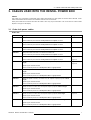
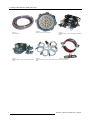
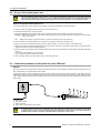
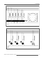
EVENTS
RENTAL POWER BOX
OWNERS MANUAL
14052004
R5976615/01
Barco nv Events
Noordlaan 5, B-8520 Kuurne
Phone: +32 56.36.89.70
Fax: +32 56.36.88.24
E-mail: [email protected]
Visit us at the web: www.barco.com
Printed in Belgium
Copyright ©
All rights reserved. No part of this document may be copied, reproduced or translated. It shall not otherwise be recorded, transmitted or
stored in a retrieval system without the prior written consent of Barco.
Guarantee and Compensation
Barco provides a guarantee relating to perfect manufacturing as part of the legally stipulated terms of guarantee. On receipt, the purchaser
must immediately inspect all delivered goods for damage incurred during transport, as well as for material and manufacturing faults Barco
must be informed immediately in writing of any complaints.
The period of guarantee begins on the date of transfer of risks, in the case of special systems and software on the date of commissioning,
at latest 30 days after the transfer of risks. In the event of justified notice of compliant, Barco can repair the fault or provide a replacement
at its own discretion within an appropriate period. If this measure proves to be impossible or unsuccessful, the purchaser can demand a
reduction in the purchase price or cancellation of the contract. All other claims, in particular those relating to compensation for direct or
indirect damage, and also damage attributed to the operation of software as well as to other services provided by Barco, being a component
of the system or independent service, will be deemed invalid provided the damage is not proven to be attributed to the absence of properties
guaranteed in writing or due to the intent or gross negligence or part of Barco.
If the purchaser or a third party carries out modifications or repairs on goods delivered by Barco, or if the goods are handled incorrectly,
in particular if the systems are commissioned operated incorrectly or if, after the transfer of risks, the goods are subject to influences not
agreed upon in the contract, all guarantee claims of the purchaser will be rendered invalid. Not included in the guarantee coverage are
system failures which are attributed to programs or special electronic circuitry provided by the purchaser, e.g. interfaces. Normal wear as
well as normal maintenance are not subject to the guarantee provided by Barco either.
The environmental conditions as well as the servicing and maintenance regulations specified in the this manual must be complied with by
the customer.
Changes
Barco provides this manual ’as is’ without warranty of any kind, either expressed or implied, including but not limited to the implied warranties or merchantability and fitness for a particular purpose. Barco may make improvements and/or changes to the product(s) and/or the
program(s) described in this publication at any time without notice.
This publication could contain technical inaccuracies or typographical errors. Changes are periodically made to the information in this
publication; these changes are incorporated in new editions of this publication.
Trademarks
Brand and product names mentioned in this manual may be trademarks, registered trademarks or copyrights of their respective holders.
All brand and product names mentioned in this manual serve as comments or examples and are not to be understood as advertising for
the products or their manufactures.
Table of contents
TABLE OF CONTENTS
1. Safety . . . . . . . . . . . . . . . . . . . . . . . . . . . . . . . . . . . . . . . . . . . . . . . . . . . . . . . . . . . . . . . . . . . . . . . . . . . . . . . . . . . . . . . . . . . . . . . . . . . . . . . . . . . . . . . . . . 3
1.1
1.2
Important Safety Instructions . . . . . . . . . . . . . . . . . . . . . . . . . . . . . . . . . . . . . . . . . . . . . . . . . . . . . . . . . . . . . . . . . . . . . . . . . . . . . . . . . . . . . . . . . . . . . . . . . . . . . . . . . 3
Important Warnings . . . . . . . . . . . . . . . . . . . . . . . . . . . . . . . . . . . . . . . . . . . . . . . . . . . . . . . . . . . . . . . . . . . . . . . . . . . . . . . . . . . . . . . . . . . . . . . . . . . . . . . . . . . . . . . . . . . 3
2. Introduction . . . . . . . . . . . . . . . . . . . . . . . . . . . . . . . . . . . . . . . . . . . . . . . . . . . . . . . . . . . . . . . . . . . . . . . . . . . . . . . . . . . . . . . . . . . . . . . . . . . . . . . . . . 5
2.1
2.2
2.3
General functionality . . . . . . . . . . . . . . . . . . . . . . . . . . . . . . . . . . . . . . . . . . . . . . . . . . . . . . . . . . . . . . . . . . . . . . . . . . . . . . . . . . . . . . . . . . . . . . . . . . . . . . . . . . . . . . . . . . 5
Order info rental power box . . . . . . . . . . . . . . . . . . . . . . . . . . . . . . . . . . . . . . . . . . . . . . . . . . . . . . . . . . . . . . . . . . . . . . . . . . . . . . . . . . . . . . . . . . . . . . . . . . . . . . . . . . . 5
Technical summary. . . . . . . . . . . . . . . . . . . . . . . . . . . . . . . . . . . . . . . . . . . . . . . . . . . . . . . . . . . . . . . . . . . . . . . . . . . . . . . . . . . . . . . . . . . . . . . . . . . . . . . . . . . . . . . . . . . . 5
3. Cables used with the rental power box. . . . . . . . . . . . . . . . . . . . . . . . . . . . . . . . . . . . . . . . . . . . . . . . . . . . . . . . . . . . . . . . . . . . . . . . . . 7
3.1
Order info power cables. . . . . . . . . . . . . . . . . . . . . . . . . . . . . . . . . . . . . . . . . . . . . . . . . . . . . . . . . . . . . . . . . . . . . . . . . . . . . . . . . . . . . . . . . . . . . . . . . . . . . . . . . . . . . . . 7
4. Physical installation . . . . . . . . . . . . . . . . . . . . . . . . . . . . . . . . . . . . . . . . . . . . . . . . . . . . . . . . . . . . . . . . . . . . . . . . . . . . . . . . . . . . . . . . . . . . . . . . 9
4.1
4.2
4.3
Components of the rental power box . . . . . . . . . . . . . . . . . . . . . . . . . . . . . . . . . . . . . . . . . . . . . . . . . . . . . . . . . . . . . . . . . . . . . . . . . . . . . . . . . . . . . . . . . . . . . . . . . 9
Set up of the rental power box . . . . . . . . . . . . . . . . . . . . . . . . . . . . . . . . . . . . . . . . . . . . . . . . . . . . . . . . . . . . . . . . . . . . . . . . . . . . . . . . . . . . . . . . . . . . . . . . . . . . . . . 10
Connections between rental power box and LED-wall. . . . . . . . . . . . . . . . . . . . . . . . . . . . . . . . . . . . . . . . . . . . . . . . . . . . . . . . . . . . . . . . . . . . . . . . . . . . . . 10
A. Addendum . . . . . . . . . . . . . . . . . . . . . . . . . . . . . . . . . . . . . . . . . . . . . . . . . . . . . . . . . . . . . . . . . . . . . . . . . . . . . . . . . . . . . . . . . . . . . . . . . . . . . . . . . . . 13
A.1
A.2
Identification system of a power distribution network according IEC 364 . . . . . . . . . . . . . . . . . . . . . . . . . . . . . . . . . . . . . . . . . . . . . . . . . . . . . . . . . . 13
Diagrams . . . . . . . . . . . . . . . . . . . . . . . . . . . . . . . . . . . . . . . . . . . . . . . . . . . . . . . . . . . . . . . . . . . . . . . . . . . . . . . . . . . . . . . . . . . . . . . . . . . . . . . . . . . . . . . . . . . . . . . . . . . . . 13
Index. . . . . . . . . . . . . . . . . . . . . . . . . . . . . . . . . . . . . . . . . . . . . . . . . . . . . . . . . . . . . . . . . . . . . . . . . . . . . . . . . . . . . . . . . . . . . . . . . . . . . . . . . . . . . . . . . . . . . . 17
R5976615 RENTAL POWER BOX 14052004
1
Table of contents
2
R5976615 RENTAL POWER BOX 14052004
1. Safety
1. SAFETY
1.1 Important Safety Instructions
Instructions:
•
Read this instructions.
•
Keep these instructions.
•
Heed all warnings.
•
Follow all instructions.
•
Do not use the power box in wet conditions.
•
Make sure that the power box is properly grounded.
•
For protection against electrocution, a disconnect device must be provided in the beginning of the main power line to the power
box.
•
Make sure the ’AC MAINS SUPPLY VOLTAGE’ selector is standing in the corresponding position to the supplied voltage before
engaging the power box.
•
Measure the outgoing voltage on the power output connectors before connecting any devices with the power box.
•
Protect the power cords from being walked on or pinched particularly at plugs, convenience receptacles, and the point where
they enter or exit the power box.
•
Refer all servicing to qualified service technicians/personnel only.
•
Do not use this power box with an IT power distribution network. A neutral conductor must be provided.
•
The centre point of the power generator must be grounded when using a local power generator.
1.2 Important Warnings
Important warnings:
•
Risk of electrical shock:
Image 1-1
Risk of electric shock. Do not open. To reduce the risk of electric shock, do not remove cover (or back). No user-serviceable
parts inside. Refer servicing to qualified service personnel.
The lightning flash with an arrowhead within a triangle is intended to tell the user that parts inside this product may cause a risk
of electrical shock to persons.
The exclamation point within a triangle is intended to tell the user that important operating and/or servicing instructions are
included in the technical documentation for this equipment.
•
Wrong selection of the ’AC MAINS SUPPLY VOLTAGE’ can cause damage to the power box and the equipment connected to it.
R5976615 RENTAL POWER BOX 14052004
3
1. Safety
4
R5976615 RENTAL POWER BOX 14052004
2. Introduction
2. INTRODUCTION
2.1 General functionality
Overview:
The rental power box provides power (230VAC) to run the full range of Barco LED Display systems (i.e. DLite, ILite and SLite). It is
dual voltage (230V/400V 3 phase) and is equipped with a digital power meter for easy voltage and current measurement. The rental
power box has three multi-pole power output connectors which provide in total 18 protected power output circuits. Furthermore the
rental power box includes three multi-purpose power outlets for energizing peripherals around the Barco LED-wall.
2.2 Order info rental power box
Order info:
Article No.
Description
R9850990
Rental power box
2.3 Technical summary
Summary:
Type
Value
Mains Input connector
CEE-form 63 A / 3 phase plus neutral (N) and protective earth (PE).
Main circuit breaker
63 A maximum, 3 phase plus neutral (N)
Short circuit rating: 10 kA 400 V or 20 kA 230 V (Norm IEC 60947–2)
Provided with a ground fault current interrupter of 300 mA.
Output connectors
Three 19 pins circular multi-pole connectors with each 6 circuits. Each circuit is
protected with a 16 A switch fuse (20 kA short circuit rating).
Three 2 phase, plus protective earth, auxiliary connectors (CEE-form) each
protected with a 16 A switch fuse (20 kA short circuit rating).
AC MAINS 230 / 400 V switch
Padlockable phase selector switch. Changeover with centre off. Select voltage
between any two phases, or between any phase and neutral.
Measure unit
Power meter PM500.
Measure functions: I, U, F, PGQ, PF/THD, Imax, Pmax, H, E
Protected with a 6 A switch fuse.
Input voltage
230 V – 3 phase
400 V – 3 phase plus neutral
Maximum input current
63 A
Suitable power nets
TT and TN. Can be used with a local power generator but the centre point of the
power generator must be grounded.
Output voltage
230 V on the multi-pole connectors and on the auxiliary connectors.
Maximum output current
6 circuits of 16 A per multi-pole connector.
16 A on the auxiliary connectors.
Ruggedness
IP30
Weight (flightcase included)
93 kg.
R5976615 RENTAL POWER BOX 14052004
5
2. Introduction
Type
Value
Dimensions flightcase.
685 x 656 x 670 (W x D x H)
Regulation compliance
CE.
IEC 60947–2.
6
Output voltage
230V on each output circuit (multi-pole and auxiliary)
Maximum output current
16A maximum for each output circuit (multi-pole and auxiliary)
R5976615 RENTAL POWER BOX 14052004
3. Cables used with the rental power box
3. CABLES USED WITH THE RENTAL POWER BOX
Cables
This chapter only enumerates and describes power cables used between the rental power box and the Barco LED-wall. Power
cables used between tiles are listed in the installation manual of the concerned tile.
Some power cables can be used as well indoor as outdoor. Other may only be used indoor. The use of indoor or outdoor cables
depend on the type of LED display.
3.1 Order info power cables
Order info:
Article No.
Description
R9851260
Multi power cable of 10 meter. For indoor and outdoor use.
Image
Used to distribute power between rental power box and spider connector.
R9851261
Multi power cable of 20 meter. For indoor and outdoor use.
Used to distribute power between rental power box and spider connector.
R9851262
Multi power cable of 30 meter. For indoor and outdoor use.
Used to distribute power between rental power box and spider connector.
R9851263
Multi power cable of 50 meter. For indoor and outdoor use.
Used to distribute power between rental power box and spider connector.
R9851264
R9851660
Multi power cable with custom length. For indoor and outdoor use.
image 3-1
Used to distribute power between rental power box and spider connector.
image 3-2
Waterproof spider connector, for outdoor use, with 6 power outputs (C19) with different
length.
image 3-3
image 3-6
Spider support bracket included.
Used to subdivide power from a multi power cable to a group of tiles.
R9851661
Waterproof spider connector, for outdoor use, with 6 power outputs (C19) with same
length.
image 3-4
Spider support bracket included.
Used to subdivide power from a multi power cable to a group of tiles.
R9851662
Waterproof spider connector, for outdoor use, with 6 power outputs (C19) with custom
length.
Spider support bracket included.
Used to subdivide power from a multi power cable to a group of tiles.
R9851670
Spider connector, for indoor use, with 6 power outputs (C19) with different length.
Spider support bracket included.
Used to subdivide power from a multi power cable to a group of tiles.
R9851671
Spider connector, for indoor use, with 6 power outputs (C19) with same length.
image 3-5
Spider support bracket included.
Used to subdivide power from a multi power cable to a group of tiles.
R9851672
Spider connector, for indoor use, with 6 power outputs (C19) with custom length.
Spider support bracket included.
Used to subdivide power from a multi power cable to a group of tiles.
R5976615 RENTAL POWER BOX 14052004
7
3. Cables used with the rental power box
Image 3-1
Multi power cable.
Image 3-4
Waterproof spider connector (output cables with same
length).
8
Image 3-2
Detail of a multi-pole connector plug.
Image 3-3
Waterproof spider connector (output cables with different
length).
Image 3-5
Image 3-6
Spider connector for indoor use (output cables with same Spider support bracket.
length).
R5976615 RENTAL POWER BOX 14052004
4. Physical installation
4. PHYSICAL INSTALLATION
4.1 Components of the rental power box
Rear side
On the rear side of the rental power box are the connectors for power input and output, as well the padlockable phase selector switch.
The number and the color of the output connectors correspond with the number and color of the switch fuses at the front side.
Image 4-1
A
B
C
D
Mains Input connector.
Padlockable phase selector switch.
Multi-pole output connectors.
Auxiliary output connectors.
Front side
At the front side are the main circuit breaker and the switch fuses of each output circuit accessible. The front side also contains
the display of the power meter. The number and the color of the switch fuses correspond with the number and color of the output
connectors at the rear side.
Image 4-2
A
B
C
Main circuit breaker.
Power meter.
Switch fuses for output circuits.
R5976615 RENTAL POWER BOX 14052004
9
4. Physical installation
4.2 Set up of the rental power box
This rental power box can only be used on a TT or TN power distribution network. Do not use this power box
with an IT power distribution network. A neutral conductor must be provided. In case of using this power box
with a power generator make sure that the centre point of the power generator is connected to the earth.
How to set up the rental power box ?
1. Place the rental power box in a safe and dry location, which is only accessible by authorized persons.
2. Lock the wheels of the flight-case and remove the front and rear cover.
3. Place all the switch fuses in the OFF position.
4. Place the padlockable phase selector switch on the matching phase to phase voltage of the local power network.
Warning: Make sure to select the correct mains voltage. Wrong selection can cause damage to the power box and the equipment connected to it.
Tip:
Measure the voltage on the mains power cord before connecting to the rental power box.
5. Place a padlock on the phase selector and connect the mains power cord to the rental power box.
6. Switch on the main circuit breaker and the switch fuse named “LOGIC”. This action will start up the power meter.
7. Read out the phase to phase supplied voltages on the power meter. See “User manual” of the power meter for instructions about
reading out the phase to phase supplied voltages.
8. Does the values of the phase to phase supplied voltages on the power meter correspond with the position of the padlocked phase
selector ?
If yes, connect the equipment to the power box.
If no, repeat this procedure starting from step 3.
9. Now it is safe to switch on all other switch fuses of the rental power box.
4.3 Connections between rental power box and LED-wall
General
The rental power box is provided with multi-pole power output connectors. One multi-pole connector contains six (6) power circuits,
each protected with a 16 ampere rated circuit breaker.
A multi power cable is used to transport the power from the multi-pole connector to a spider connector. This spider connector
subdivide the power circuits into individual power source cables. Each power source cable of the spider connector leads to a group
of tiles. See installation manual of the involved tiles to know the maximum amount of tiles connected in parallel with the same power
source cable.
A
B
C
D
Image 4-3
A
B
C
D
Power box.
Multi power cable.
Spider connector.
Power source cable (spider output cable).
To protect against risk of fire by overloading of power cables, the amount of tiles per power source cable
is limited. Never connect more tiles than allowed. See installation manual of the involved tiles to know the
maximum amount of tiles connected in parallel with the same power source cable.
10
R5976615 RENTAL POWER BOX 14052004
4. Physical installation
Necessary parts
•
Multi power cables
•
Spider connectors
•
Spider support brackets
•
Power source cables
How to realize the connections between the rental power box and the LED-wall ?
1. Install a spider support bracket at the rear side of the LED-wall. Choose a place where all output cables of the spider connector
will easily connect to the start point of a power branch.
2. Fasten the multi-pole plug of a spider connector inside the spider support bracket.
Warning: Always use waterproof spider connectors in case of an outdoor LED-wall application.
3. Connect a single power source cable of the spider connector with the start point of a power branch of tiles in the LED-wall.
4. Repeat step 3 until all six power source cables of the spider connector are connected with the LED-wall.
5. Connect a multi power cable with the spider connector. Ensure to fasten the locking cap of the spider connector.
6. Connect the other side of the multi power cable with one of the multi-pole sockets on the rental power box. Ensure to fasten the
locking cap of the multi-pole plug.
Warning: Ensure the rental power box is switched off.
7. Repeat from step 1 until all multi-pole sockets of the rental power box are used.
R5976615 RENTAL POWER BOX 14052004
11
4. Physical installation
12
R5976615 RENTAL POWER BOX 14052004
A. Addendum
A. ADDENDUM
A.1 Identification system of a power distribution network according IEC1 364
TT, IT, TN-C and TN-S
The first character indicates the position of the neutral conductor:
•
T : Directly connected with the protective earth.
•
I : Isolated from the protective earth or connected through an impedance.
The second character indicates the grounding manner of electrical equipment:
•
T : Directly connected with the protective earth.
•
N : Connected with the neutral conductor of the power source.
The third character indicates the situation of the neutral (N) conductor and the protective earth (PE) conductor:
•
C : Common conductor for neutral and protective earth.
•
S : Separated conductors for neutral and protective earth.
A.2 Diagrams
Internal wiring diagrams:
300mA
Phase
Selector
Switch
220V/400V
63A
Power meter PM500
Image A-1
1. International Electro-technical Commission
R5976615 RENTAL POWER BOX 14052004
13
A. Addendum
Image A-2
Image A-3
14
R5976615 RENTAL POWER BOX 14052004
A. Addendum
Image A-4
LOGIC
Power
Meter
Image A-5
R5976615 RENTAL POWER BOX 14052004
15
A. Addendum
16
R5976615 RENTAL POWER BOX 14052004
Index
INDEX
A
Addendum
Power box
5
13
P
C
Cables 7
Components 9
Connections 10
Power box 10
Power box 5, 10
Connections 10
General functionality
Order info 5
Set up 10
D
R
Diagrams
Rental Power Box 5
Technical summary
13
G
General functionality
Power box 5
5
I
IEC 364 13
Installation 9
Introduction 5
5
5
S
Safety 3
Important Safety Instructions
Important Warnings 3
Set up 10
Power box 10
3
T
Technical summary
5
O
Order info
5, 7
R5976615 RENTAL POWER BOX 14052004
17


![FLM integration rod replacement + adjustment [v00]](http://vs1.manualzilla.com/store/data/005734078_1-ffddbeaec5f2fd08f6ea79cefb7ee063-150x150.png)


![Overview cPR67 and cPR84 [v00]](http://vs1.manualzilla.com/store/data/005648847_1-d158a5d3d4b92d14c7a3179652b88ffd-150x150.png)
![Theater Management Software V5.6 [v06]](http://vs1.manualzilla.com/store/data/005786775_1-99bc430d529a8a144d04bed9ea0580b8-150x150.png)
![Multi Input Module for OverView D user`s manual [v07]](http://vs1.manualzilla.com/store/data/005713215_1-e2d53d24a0a93d32e9e353f3f6c133cd-150x150.png)

![OverView Control Manager user`s manual - operator [v04]](http://vs1.manualzilla.com/store/data/005659468_1-4c522981c7089838b286d7fbb1120c24-150x150.png)