1
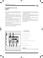
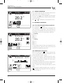
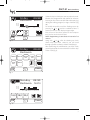
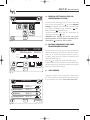
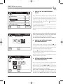
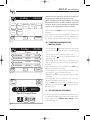
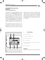
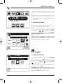
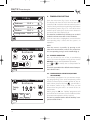
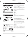
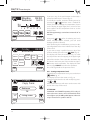
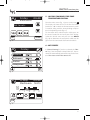
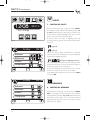
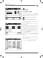
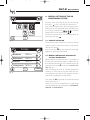
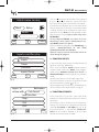
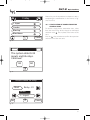
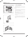
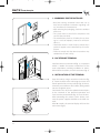
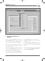
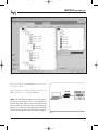
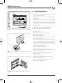
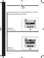
OHT01_EN 24081022 07_06.qxd
20/07/2006
15:31
Pagina 1
Instructions for user and installer for control
and programming terminals
T
TEMP
DOMO
12:08
20.2°c
Fri 12 May
ENTER
EXIT
NIGHT
OH/T.01
Basic Interface
Climate
Lights
Openings Scenarios
12:08
20.2°c
Fri 12 May
SCENE
OH/T.01
Interface Plus
07.2006 / 24081022
SCENE
Timers
SCENE
OHT01_EN 24081022 07_06.qxd
20/07/2006
Congratulations on your purchase of an OH/T.01
control terminal for the Hoasis system, will allows
you to manage the automation in your home.
The terminal lets you manage two types of functions
on the display which are called Basic Interface and
Interface Plus.
You can upgrade the terminal from the "Basic" to
the "Plus" version by contacting a qualified
installer. Therefore, this manual is divided into
two parts. Each part illustrates the special features and functions of the two available versions
of software and the corresponding interface.
To get the most out of this unit, and to take full
advantage of its characteristics and functions, please
carefully read this manual and keep it available for
future reference.
The OH/T.01 Terminal is equipped with a bag of
accessories containing dowels, screws, pens and
connector for connection.
The instruction booklet includes a warranty certificate for any repairs which the unit may require.
2
15:31
Pagina 2
OHT01_EN 24081022 07_06.qxd
20/07/2006
15:31
Pagina 3
Index
T
TEMP
DOMO
12:08
20.2°c
EXIT
Lights
Openings
12:08
Scenarios
Timers
20.2°c
Fri 12 May
Fri 12 May
ENTER
Climate
NIGHT
SCENE
SCENE
SCENE
OH/T.01
OH/T.01
Basic Interface
Interface Plus
User instructions
User instructions
CHAPTER
Page
1 -Description ..........................................................................6
2 -Setting the clock..............................................................7
3 -Temperature setting ....................................................7
3.1 -Manual operation ..................................................8
3.2 -Automatic operation ............................................8
3.2a - Pre-set heating and cooling programmes 8
3.2b - Modification of programs ................................8
3.2c - Setting temperature levels .............................. 10
4 - General settings of the air conditioning
system .................................................................................. 11
5 - Locking commands for zone temperature
control .................................................................................. 11
6 - Anti-freeze ........................................................................11
7 - Display of air conditioning zones ......................12
8 - Display of installed home automation zones..12
9 - Setting operation of home automation
zones...................................................................................... 12
10 - Timer programming and modification ........13
11 - Activation of scenarios ............................................13
CHAPTER
Page
1 -Description ......................................................................16
2 -Setting the clock ..........................................................17
CLIMATE
3 - General Settings............................................................ 17
4 - Temperature setting ................................................ 18
4.1 - Manual operation .............................................. 18
4.2 - Manual operation
timed (Holiday programme) ........................ 18
4.3 - Automatic operation ........................................ 19
4.3a - Pre-set heating and cooling
programmes .......................................................... 19
4.3b - Programme modification .............................. 19
4.3c - Setting temperature levels .............................. 20
5 - Locking commands for zone temperature
control .................................................................................. 21
6 - -Anti-freeze ........................................................................21
LIGHTS
7 - Control of lights ............................................................ 22
OPENINGS
8 - Control of openings.................................................... 22
SCENARIOS
9 - Control of Scenarios .................................................. 23
TIMERS
10 - Control of timers .......................................................... 24
11 - Activation of pre-set scenarios .......................... 25
3
OHT01_EN 24081022 07_06.qxd
T
TEMP
20/07/2006
DOMO
12:08
20.2°c
EXIT
Pagina 4
Climate
Lights
Openings
12:08
Scenarios
Timers
20.2°c
Fri 12 May
Fri 12 May
ENTER
15:31
NIGHT
SCENE
SCENE
SCENE
OH/T.01
OH/T.01
Basic Interface
Interface Plus
Installer instructions
Installer instructions
CHAPTER
Page
1 - Warnings for the installer ........................................28
2 - Location of terminal ....................................................28
3 - Installation of the terminal ....................................28
4 - Setting the clock ............................................................30
5 - Configuration and programming of air
conditioning zones .................................................... 30
6 - General settings of the air conditioning
system .................................................................................. 33
6.1 - Advance activation..............................................33
6.2 - manual temperature variation on the
OH/Z thermostats .............................................. 33
7 - Configuration of
zones of home automation control ................ 34
8 - Choice of inputs ............................................................ 35
9 - Function of inputs........................................................ 35
10 - Modification of home automation
control zones ....................................................................36
10.1 - Cancellation of home automation
control zones ........................................................37
11 - Useful information ...................................................... 38
12 - Technical features ...................................................... 39
4
CHAPTER
Page
1 - Warnings for the installer ........................................42
2 - Location of terminal ....................................................42
3 - Installation of the terminal ....................................42
4 - Installing the Hoasis Plus interface.................. 44
5 - Useful information ........................................................46
6 - Technical characteristics.......................................... 46
OHT01_EN 24081022 07_06.qxd
20/07/2006
15:31
Pagina 5
OH/T.01 Basic interface
User's manual
5
OHT01_EN 24081022 07_06.qxd
20/07/2006
15:31
Pagina 6
OH/T.01 Basic interface
User's manual
PROGRAMMING AND CONTROL
TERMINAL
OH/T.01
The unit allows you to control and activate the main
building services in a HOASIS home automation control system.
The HOASIS home automation control system is
composed of two main units, the OH/T.01 programming and control terminal and an OH/A activation
and power supply unit.
The system manages up to 64 relays and 71 contact
inputs, including 7 of the OH/Z zone modules.
The terminal makes it possible to program the temperature, and to manage lights, irrigation systems,
automation devices, etc.
In thermal adjustment mode, the unit combines various functions: summer/winter, anti-freeze, pre-set
programmes, date and time display.
In home automation operation mode, it allows the
control of relays with timers, scenarios or activations
commanded by the user.
The touch-screen technology makes it possible to set
all parameters and programming, just by touching
the icons on the display.
On-line help guides the user through the programming of the various functions.
Communication between the various units in the system takes place by means of a bus realized on a single twisted pair.
1 - DESCRIPTION 9
1
2
3
1 Pen for touch screen.
2 Go back to previous menu.
Friday
Venerdi
09:35
Camere
16.0°c
Bedroom
HOME
20,0
18,0
16,0
1
MANUAL
I
I
I
I
0
6
12
18
12
1
OFF
?
OK
4 Cancel operation.
I
24
24
AUTO
12
3 Display touch screen.
24
CHANGE
5 Push button to lock controls on display.
Cancel
6 On-line help.
7 Confirm operation.
7
6
5
4
WARNINGS
For proper use of the unit, use the special pen provided.
Fig. 1
6
OHT01_EN 24081022 07_06.qxd
20/07/2006
15:31
Pagina 7
OH/T.01 Basic interface
User's manual
2 - SETTING THE CLOCK
°C
T
TEMP
DOMO
9:15
23.5°c
Tue 30 September
Fig. 2
From the main menu (fig. 2) press on the strip where
the time and temperature are displayed. The display
will show the menu Set time and date (fig. 3)
Select the box where you want to update the data
and press on
or
to modify it.
Press OK to confirm the operation. Press on the icon
ACTIVATE DAYLIGHT SAVINGS TIME to activate or
deactivate daylight savings time.
NOTE. If activated, changeover to daylight savings
time takes place automatically. This operation will
not take place if there is no power supply.
3 - TEMPERATURE SETTING
HOME
Set time and date
Time:
10
12
ENABLE
SAVINGS
TIME
From the main menu (fig. 2) press on the icon
.
The display will show the list of the possible first four
zones (maximum 8) in which the climate control system is installed, along with the corresponding temperature and operating mode (fig. 4).
Off
Date:
01
Oct
?
OK
03
Automatic mode
Cancel
Manual mode
Fig. 3
Friday
HOME
Bedroom
20.2 °c
Bathrooms
22.0 °c
Kitchen
20.5 °c
Living room 20.5 °c
?
Cancel
Fig. 4
7
OHT01_EN 24081022 07_06.qxd
20/07/2006
15:31
Pagina 8
OH/T.01 Basic interface
User's manual
Friday
Venerdi
HOME
09:30
Bedroom
20.2
1
MANUAL
12
°C
3.2 -AUTOMATIC OPERATION
24
AUTO
OFF
?
OK
Friday
Venerdi
09:30
Bedroom
20.2
1
MANUAL
12
°C
24
AUTO
OFF
?
OK
3.2a - Pre-set heating and cooling programmes
Press on the icon
(AUTO).
The operation of the thermostats throughout the
day is shown by a diagram (fig. 7, fig. 8) with hours of
the day on the horizontal axis and the three pre-set
temperature levels on the vertical axis, which are:
For heating
T1 16 °C
T2 18 °C
T3 20 °C
For cooling
T1 24 °C
T2 26 °C
T3 28 °C
The terminal contains the preset temperature levels
and programmes, valid for all days of the week and
which can be modified as you wish.
1
Fig. 5
HOME
3.1 - MANUAL OPERATION
Press on the square for the first climate control zone
(fig. 4). The menu will appear as in fig. 5.
Press on the icon to activate MANUAL operation (fig. 6)
The unit is provided with a default manual temperature level of 20 °C.
Press or to modify the set temperature level..
Fig. 6
12
24
3.2b -Modification of programs
When the (AUTO) icon
has been activated, figures 7-8, the profile of the set temperature for the
current day of the week is shown.
The trend of the profile is obtained from the representation of the highest value for each hour of the
day. The flashing cursor indicates the time corresponding to the clock time.
It is possible to display the trend of the enlarged profile (6 hours) by pressing on the same profile.
After 5 seconds the 24 hour profile will be shown
again.
If you want to modify the profile, press on the icon
(CHANGE). The display will show a list of the days
of the week (fig. 9).
1
Friday
Venerdi
09:35
Camere
16.0°c
Bedroom
HOME
20,0
18,0
16,0
1
MANUAL
OK
Fig. 7
8
I
I
I
I
0
6
12
18
12
1
24
AUTO
I
24
OFF
?
12
24
CHANGE
1
12
24
12
24
OHT01_EN 24081022 07_06.qxd
20/07/2006
15:31
Pagina 9
OH/T.01 Basic interface
User's manual
Friday
Venerdi
09:35
Camere
24.0°c
Bedroom
HOME
28,0
26,0
24,0
1
MANUAL
I
I
I
I
0
6
12
18
12
I
24
1
24
AUTO
OFF
12
24
CHANGE
?
OK
Fig. 8
Friday
Venerdi
09:40
Camere
Bedroom
HOME
MONDAY
TUESDAY
SATUR
DAY
SUNDAY
THURS
DAY
WEDNES
DAY
FRIDAY
T1
T2
T3
1
?
12
24
1
12
24
COPY
LEVELS
OK
Select the day in which you want to make the modification, the programmed daily profile for 24 hours.
Pressing on any of those underneath will display (e.g.
during the heating program) a range of 6 hours (fig.
10).
To modify the profile, scroll the flashing cursor by
pressing on
or
until the established time is
reached, shown on the display at upper right.
Press on one of the three squares for the temperature level to set the desired value.
NOTE. Programming is carried out in intervals of 15
minutes.
Using only
or
, after de-selecting any levels
which may have been selected, you can scroll
through a profile to check it without modifying it.
After confirming the modifications you have made,
you will go back to the menu with the list of the days
of the week (fig. 9).
Cancel
Fig. 9
Lunedi
Monday 09:30
Camere
16.0°c
Bedroom
HOME
20,0
18,0
16,0
I
I
I
I
I
I
I
7
8
9
10
11
12
13
16,0 18,0 20,0
OK
?
Cancel
Fig. 10
9
OHT01_EN 24081022 07_06.qxd
20/07/2006
15:31
Pagina 10
OH/T.01 Basic interface
User's manual
HOME
MONDAY
Friday
Venerdi 09:40
Copy from:
Bedrooms
In:
SATUR
DAY
OK
Living room
?
End
Fig. 11
Venerdi
Friday
HOME
09:40
Bedroom
16,0 18,0 20,0
Fig. 12
10
?
3.2c -Setting temperature levels
To modify the 3 temperature levels, press on the icon
(LEVELS), fig. 9. The display will show the menu as
in fig. 12.
Select one of the 3 levels and press on
or
to
modify the value.
After confirmation you will return to the menu with
the list of the days of the week.
WARNING. In MANUAL or AUTOMATIC operation, if
the relay relative to the zone is active, on the lefthand side of the menu (figures 6-7) the message ON
appears.
When the relay is not active the message ON is not
present.
Set levels:
OK
If you want to copy a set temperature profile, press
on COPY (fig. 9).
The display will show the menu as in fig. 11. Select
the day and the zone from which to copy and transfer the desired profile.
Press OK to confirm the operation. The display will
show the message COPIED to confirm the operation.
Press End to go back to the previous menu.
Cancel
OHT01_EN 24081022 07_06.qxd
20/07/2006
15:31
Pagina 11
OH/T.01 Basic interface
User's manual
4 - GENERAL SETTINGS OF THE AIR
CONDITIONING SYSTEM
HOME
General settings
SUMMER
WINTER
OFF
ANTICIP.
+/– 8°C
°C
From the main menu (fig. 2) press on the icona T ,
then on the next menu press
, the menu General
settings will appear. From this menu you can select
the system operating mode: COOLING (
SUMMER), HEATING ( WINTER (fig. 13).
All climate control zones can be deactivated by
pressing on the icon
(OFF).
WARNING. After selecting one of the two system
operating modes, all of the climate control zones are
deactivated ( on OH/T.01, OFF on OH/Z).
TEMP
?
OK
Fig. 13
5 - LOCKING COMMANDS FOR ZONE
TEMPERATURE CONTROL
Friday
Venerdi
09:35
Camere
Bedroom 16.0°c
HOME
20,0
18,0
16,0
1
MANUAL
I
I
I
I
0
6
12
18
12
1
24
AUTO
I
24
OFF
LOCK
12
24
CHANGE
?
OK
°C
From the main menu (fig. 2) press on the icon T . The
display will show the list of the first four zones (maximum 8) in which the climate control system is
installed, along with the relative temperature and
operating mode (fig. 15).
Press on to display the other 4 possible zones.
Select the desired zone and press on icon BLOCK (fig.
14) to deactivate the commands which can be given
from the OH/Z control module.
TEMP
6 - ANTI-FREEZE
Fig. 14
During the winter, if the temperature drops below
8°C, the terminal will automatically activate the antifreeze function. This occurs even if the zone is off.
Tuesday
HOME
Bedroom
20.2 °c
Bathrooms
22.0 °c
Kitchen
19.5 °c
Living room
20.0 °c
?
Cancel
Fig. 15
11
OHT01_EN 24081022 07_06.qxd
20/07/2006
15:31
Pagina 12
OH/T.01 Basic interface
User's manual
7 - DISPLAY OF AIR CONDITIONING
ZONES
Tuesday
HOME
°C
Bathrooms
TEMP
Bedroom
Kitchen
Living room
?
Cancel
Fig. 16
Friday
Venerdi
HOME
09:50
Bedroom
AUTO
From the main menu (fig. 2) press on the icon T .
The display will show the list of the first four zones
(maximum 8) in which the climate control system is
installed, along with the relative temperature and
operating mode (fig. 15). Press on to display the
other 4 possible zones.
This information will be shown after carrying out the
programming procedure.
When the name of the zone is highlighted, it means
that the system is in operation (the relative relay is
active).
OFF
NOTE. From this menu it is possible, by pressing on the
name of the involved zone, to access the menu where
the settings you have made can be modified.
For this operation, follow the instructions in chapter 3.
8 - DISPLAY OF INSTALLED HOME
AUTOMATION ZONES
ON
From the main menu (fig. 2) press on the icon , . The
display will show the list of the first four zones/service
(maximum 32, without climate control zones) that the
home automation system controls (fig. 16).
Press on to display the other zone/services.
This information will be shown after carrying out the
programming procedure.
When the name of the zone is highlighted, it means
that the relative relay is active.
DOMO
?
OK
Fig. 17
Venerdi
Friday
HOME
AUTO
OFF
MO
DAY
OK
Fig. 18
12
09:50
Bathrooms
Timer 01
ACTIVAT.
?
ON
9 - SETTING OPERATION OF HOME
AUTOMATION ZONES
Press on one of the zones included (e.g. Bedrooms)
in the list in fig. 16 to display the menu in fig. 17.
By pressing on the icon OFF or ON it is possible to
force the exclusion of the zone, thus deactivating the
functions programmed at installation.
NOTE. When controlling the OH/MA modules, the
forcing function TURNED OFF by the OH/T.01 terminal does not disable local controls or other pro-
OHT01_EN 24081022 07_06.qxd
20/07/2006
15:31
Pagina 13
OH/T.01 Basic interface
User's manual
Friday
Venerdi
FRIDAY
grammed remote controls as it only has a stop function during opening and closing movements.
When controlling the NH-DIM modules, the forcing
function OFF only has an OFF function as regards to
the active dimmer control and does not disable local
controls or other programmed remote controls.
Cancel
Press on the icon AUTO to restore the programmed
functions.
If the selected zone is also controlled by one or more
timers and is in Automatic mode (e.g. Bathrooms in
fig. 16), the display will show the menu as in fig. 18.
09:50
HOME
MONDAY
TUESDAY
SATUR
DAY
SUNDAY
WEDNES
DAY
THURS
DAY
?
OK
Fig. 19
HOME
10 - TIMER PROGRAMMING AND
MODIFICATION
Friday
Venerdi
from
09:55
to
Activation
02:00
04:00
Activation
06:00
08:00
Activation
00:00
00:00
Activation
00:00
00:00
?
OK
Cancel
Fig. 20
TTEMP°C
DOMO
9:15
23.5°c
Press on the icon MO (DAY) to choose the days of the
week in which you want the timer to be active (fig.
19).
Press on OK to return to the previous menu.
Press on the icon
. The list of timer activations will
appear (fig. 20).
By selecting one of these (up to 4 activations per
day) it is possible to set the interval of operation of
the timer.
Upon completion of this operation press OK to go
back to the previous menu (fig.
If more than one timer has been installed in the
zone, press on
to select the next one.
Repeat the operations of the previous timer for programming.
The relay will then be activated for each programmed activation of the timers.
Press on End, the zone menu is displayed (fig. 16)
and then press on the icon
to return to the initial menu (fig. 2).
11 - ACTIVATION OF SCENARIOS
Tue 30 September
ENTER
EXIT
NIGHT
If functions have been matched to the three scenarios during installation, pressing on one of these icons
in the main menu (ENTER, EXIT, NIGHT) ENTER,
EXIT, NIGHT (fig. 21).
Fig. 21
13
OHT01_EN 24081022 07_06.qxd
20/07/2006
This section of the manual is for users who have
upgraded the Hoasis system from the "Base"
version to the "Plus" version with the PC HOME
programme on the OH/T.01.
14
15:31
Pagina 14
OHT01_EN 24081022 07_06.qxd
20/07/2006
15:31
Pagina 15
OH/T.01 Interface plus
User's manual
15
OHT01_EN 24081022 07_06.qxd
20/07/2006
15:31
Pagina 16
OH/T.01 Interface plus
User's manual
PROGRAMMING AND CONTROL
TERMINAL
OH/T.01 INTERFACE PLUS
The unit allows you to control and activate the main
building services in a HOASIS PLUS home automation control system. The HOASIS PLUS home
automation control system is composed of two main
units, the OH/T.01 control terminal and the
OH/A.01 power supply unit. The system manages up
to 255 relays and 255 contact inputs, 19 of which can
be heat-controlled OH/Z.02. The terminal makes it
possible to program the temperature, and to manage lights, irrigation systems, automation devices,
etc.
In thermal adjustment mode, the unit combines various functions: summer/winter, anti-freeze, pre-set
programmes, date and time display. In home
automation operation mode, it allows the control of
relays with timers, scenarios or activations commanded by the user. The touch-screen technology
makes it possible to set all parameters and programming, just by touching the icons on the display.
Communication between the various units in the system takes place by means of a bus realized on a single twisted pair.
1
2
-
DESCRIPTION
3
1 Pen for touch screen.
2 Go back to previous menu.
Venerdi
09:35
Friday
Camere
16.0°c
Bedroom
HOME
20,0
18,0
16,0
1
MANUAL
I
I
I
I
0
6
12
18
12
1
OFF
OK
4 Cancel operation.
I
24
24
AUTO
3 Display touch screen.
12
24
CHANGE
Cancel
5 Button to lock controls on display and turning on
of back-lighting.
6 Confirm operation.
6
Fig. 1
16
5
4
WARNINGS
For proper use of the unit, use the special pen provided.
OHT01_EN 24081022 07_06.qxd
20/07/2006
15:31
Pagina 17
OH/T.01 Interface plus
User's manual
Climate
Lights
Openings
:08
12
Fri 12 May
Timers
Scenarios
20.2°c
The Hoasis Plus system makes it possible to control
thermal zones, lights, openings, scenarios and
timers.
After upgrading the system from the Basic version to
the Plus version with the PC HOME programme on
the OH/T.01 terminal, the screen display will be
shown as in Fig. 2.
2- SETTING THE CLOCK
SCENE
SCENE
SCENE
Fig. 2
HOME
Set time and date
Time:
10
12
ENABLE
SAVINGS
TIME
Date:
01
Oct
03
OK
From the main menu (fig 2) press on the strip where
the time and temperature are displayed.
The display will show the menu Set time and date
(fig. 3). Select the box where you want to update the
data and press on
or
to modify it. Press OK to
confirm the operation. Press on the icon ACTIVATE
DAYLIGHT SAVINGS TIME to activate or deactivate
daylight savings time.
NOTE. If activated, changeover to daylight savings
time takes place automatically. This operation will
not take place if there is no power supply.
Cancel
Fig. 3
Climate
3 - GENERAL SETTINGS
Friday
General settings
SUMMER
OK
WINTER
CLIMATE
OFF
From the main menu (fig. 2) press on the CLIMATE
icon and then on the icon
to access the window
shown in fig. 4 where you can select the system
operating mode: COOLING ( SUMMER), HEATING
( WINTER) (fig. 4).
All climate control zones can be deactivated by
pressing on the icon
(OFF).
ATTENTION. After selecting one of the two system
operating modes, all of the climate control zones are
deactivated ( on OH/T, OFF on OH/Z).
Fig. 4
17
OHT01_EN 24081022 07_06.qxd
20/07/2006
15:31
Pagina 18
OH/T.01 Interface plus
User's manual
4 - TEMPERATURE SETTING
Friday
HOME
From the main menu (fig. 2) press on the icon
.
The display will show the list of the first four zones
(maximum 20) in which the climate control system is
installed, along with the corresponding temperature
and operating mode (fig. 5). To view other zones
which may be visible, press on the arrows located in
the lower part of the display (fig. 5).
The 20 zones available may contain up to 19 OH/Z
modules and not more than 3 OH/T modules.
If one or more zones is highlighted, it means that the
corresponding relay is active and the system is in
operation.
NOTE.
From this menu it is possible, by pressing on the
name of the involved zone, to access the menu where
the corresponding settings can be modified (fig. 6).
climate
Bedroom
20.2 °c
Bathrooms
22.0 °c
Kitchen
20.5 °c
Living room 20.5 °c
Fig. 5
Friday
Venerdi
09:30
Bedroom
4.1 - MANUAL OPERATION
Press on the box for one of the air conditioning
zones. The menu will appear as in fig. 6. Press on the
MANUAL icon to activate MANUAL operation.
Press
or
to modify the set temperature for
the zone.
The unit is provided with a default manual temperature level of 20 °C.
Holiday
MANUAL
AUTO
OFF
OK
Fig. 6
Friday
Venerdi
Bedroom
Temp.
Set
TEMP
OK
Fig. 7
18
GG
HH
DAYS
HOURS
09:30
4.2 - TIMED MANUAL OPERATION (HOLIDAY
PROGRAMME)
The "Holiday" programme lets you activate temporary programming of the zone temperature, which
will be in effect only for a certain number of days or
hours. When you press this icon Holiday , you will access
the window shown in fig. 7. From here you can
choose how long the zone is to remain at the set
temperature.
When you press OK, the "Holiday" programme will
be in effect for the amount of time established. After
that, automatic operation will be restored.
The unit is provided with a default "Holiday" temperature level of 20 °C.
OHT01_EN 24081022 07_06.qxd
20/07/2006
15:31
Pagina 19
OH/T.01 Interface plus
User's manual
Friday
Venerdi
09:35
Camere
Bedroom 16.0°c
MANUAL
AUTO
OFF
CHANGE
OK
Fig. 8
Friday
Venerdi
09:35
Camere
Bedroom 24.0°c
MANUAL
AUTO
OFF
CHANGE
OK
Fig. 9
Friday
Venerdi
09:50
Bedroom
MONDAY
TUESDAY
SATUR
DAY
SUNDAY
OK
WEDNES
DAY
THURS
DAY
FRIDAY
LEVELS
COPY
4.3 - AUTOMATIC OPERATION
4.3a - Pre-set heating and cooling programmes
Press on the icon AUTO (fig. 8).
Operation of the thermostats during the course of
the day is shown by a diagram (fig. 8, fig. 9) which
shows on the horizontal axis the hours of the day
and on the vertical axis 3 preset temperature levels
which are:
For heating
T1 16 °C
T2 18 °C
T3 20 °C
For cooling
T1 24 °C
T2 26 °C
T3 28 °C
The terminal contains the preset temperature levels
and programmes, valid for all days of the week and
which can be modified as you wish.
4.3b - Programme modification 19
When the AUTO icon has been activated (figures 8,
9) the profile of the set temperature for the current
day of the week is shown.
The trend of the profile is obtained from the representation of the highest value for each hour of the day.
The cursor flashes at the current hour.
When you press on the profile, an enlarged portion
of six hours of the profile will be displayed.
After 5 seconds the display will again show the 24hour profile.
If you want to modify the profile, press on the icon
CHANGE (fig.9).
The display will show a list of the days of the week
(fig. 10).
When you select the day for which you wish to make
the change, the programmed daily profile in the 24
hours (fig. 11).
Cancel
Fig. 10
19
OHT01_EN 24081022 07_06.qxd
20/07/2006
15:31
Pagina 20
OH/T.01 Interface plus
User's manual
Monday
Lunedi
Bedroom
Camere
09:30
16.0°c
OK
Cancel
Fig. 11
Friday
Venerdi
09:50
Bedroom
If you press any of the push buttons underneath, a
time period of 6 hours is shown (fig. 11).
To modify the profile, scroll the flashing cursor by
pressing on
or
until the time is reached for
which you wish to change the temperature (shown
on the display at upper right). Press on one of the
three squares for the temperature level to set the
desired value.
NOTE. Programming is carried out in intervals of 15
minutes.
Using only
or
, after de-selecting any levels
which may have been selected, you can scroll
through a profile to check it.
After confirming the modifications you have made,
you will go back to the menu with the list of the days
of the week.
If you want to copy a profile from one day of the
week to another, press the icon
COPY (fig. 12).
The display will show the menu as in fig. 13; select
the day and the zone for copying in the upper right
part of the window. Then select the destination day
and zone in the lower part of the window and press
OK to carry out the operation. The display will show
the message COPIED to confirm the operation.
Press End to go back to the previous menu.
COPY
MONDAY
TUESDAY
SATUR
DAY
SUNDAY
WEDNES
DAY
THURS
DAY
FRIDAY
LEVELS
COPY
OK
Cancel
Fig. 12
4.3c - Setting temperature levels
To modify the 3 temperature levels, press on the icon
LEVELS, fig. 12.
The display will show the menu as in fig. 14.
Select one of the three levels and modify it by pressing
or
.
After confirmation you will return to the menu with
the list of the days of the week.
LEVELS
Venerdi 09:40
Friday
Copy from:
MONDAY
Bedroom
ATTENTION!
In MANUAL or AUTOMATIC operation, if the relay relative to the zone is active, on the left-hand side of the
menu (figures 6, 8) the ON symbol appears. When the
relay is not active the symbol is absent.
In:
SATUR
DAY
OK
Fig. 13
20
Living room
End
OHT01_EN 24081022 07_06.qxd
20/07/2006
15:31
Pagina 21
OH/T.01 Interface plus
User's manual
Venerdi
09:45
Friday
Bedroom
5 - LOCKING COMMANDS FOR ZONE
TEMPERATURE CONTROL
From the main menu (fig. 2) press on the icon
The display will show the list of the first four zones
(maximum 20) in which the climate control system
is installed, along with the corresponding temperature and operating mode (fig. 15).
To view other zones which may be visible, press on
the arrows located in the lower part of the display.
Select the desired zone and press on icon BLOCK
(fig. 16) to deactivate the commands which can be
given from the connected OH/Z control module.
climate
Set levels:
OK
Cancel
Fig. 14
6 - ANTI-FREEZE
Friday
In "General Settings", if you have selected the "Winter" key, if the temperature drops below 8°C, the terminal will automatically activate the anti-freeze function. This occurs even if the zone is off.
Bedroom
Bathrooms
Kitchen
Living room
Fig. 15
Friday
Venerdi
09:35
Camere
Bedroom 16.0°c
MANUAL
AUTO
OFF
LOCK
CHANGE
OK
Fig. 16
21
OHT01_EN 24081022 07_06.qxd
20/07/2006
15:31
Pagina 22
OH/T.01 Interface plus
User's manual
Lights
Climate
Lights
Openings
12:08
Scenarios
Timers
7 - CONTROL OF LIGHTS
20.2°c
From the main menu (fig. 17) press the icon LIGHTS.
The display will show the first four lighting points (up
to 100) controlled by the Hoasis Plus system (fig. 18).
To view other installed lighting points, press on the
arrows on the lower part of the display.
The icons show the status of lighting points. By
pressing on them you can turn the connected lights
on or off.
Fri 12 May
SCENE
LIGHTS
SCENE
SCENE
Fig. 17
Light Off
Friday
Venerdi
09:35
Bedroom
Bathrooms
Variation of lighting intensity
You can change the luminosity of the light to 5 different intensity levels. You can also turn the light on
or off by pressing on the status icon.
The level of lighting intensity that you set is memorized for the next time you turn on the lights.
To go back to the initial screen, press the key Home
or the key OK.
Kitchen
Living room
OK
Fig. 18
Friday
Venerdi
Light On
If the list includes lights controlled by a Dimmer
module, you can also change the intensity of light by
pressing the appropriate icons:
09:35
Openings
Bedroom
OPENINGS
8 - CONTROL OF OPENINGS
Bathroom
Kitchen
Living room
OK
Fig. 19
22
From the main menu (fig. 17) press the icon OPENINGS. The display will show the first four available
opening/closing devices (up to 40) controlled by the
Hoasis Plus system (fig. 19). To view other installed
opening/closing devices, press on the arrows at the
bottom of the display.
OHT01_EN 24081022 07_06.qxd
20/07/2006
15:31
Pagina 23
OH/T.01 Interface plus
User's manual
To activate one of the opening on the list in a direction or in the opposite direction, you only need to
press on the keys
or
for the corresponding
opening. Once you have pressed the opening (or
closing button), it will be activate for a length of time
as established during system installation.
During activation, the arrow that corresponds to the
activated direction will be highlighted on the display.
To stop activation, press on the key with the opposite direction of the active one (bold-face arrow on
screen).
To go back to the initial screen, press the key Home
or the key OK.
Friday
Good night
Wake up
Party
Video
OK
Fig. 20
Friday
Venerdi
09:35
Good night
Modify
Wake up
Modify
Party
Modify
Video
Modify
OK
Fig. 21
Friday
Venerdi
Yard lights
Patio lights
Irrigation
Laundry
OK
Fig. 22
09:35
Scenarios
SCENARIOS
9 - CONTROL OF SCENARIOS
From the main menu (fig. 17) press the icon
SCENARIOS. The display will show the first four available scenarios (up to 16) installed in the Hoasis Plus
system (fig. 20). To view other scenarios press on the
arrows at the bottom of the display.
To activate one of the scenarios on the list, press the
corresponding ON key.
You can also modify the sequence of actions activated in each single scenario.
If you press on the key showing a spanner , the
list of scenarios will be shown again.
If you press the Modify key located alongside the scenario name (fig. 21) you will be shown the list of activations assigned to it during the installation phase.
Using the ON and OFF keys (fig. 22) you can exclude or
include the activations connected to the scenario.
To view other activations connected to the scenario
(up to 10) press on the arrows at the bottom of the display.
To go back to the list of scenarios, press the key
Home or the key OK.
From the list of scenarios to go back to the initial
screen, press the key Home or the key OK.
23
OHT01_EN 24081022 07_06.qxd
20/07/2006
15:31
Pagina 24
OH/T.01 Interface plus
User's manual
Friday
Timers
Irrigation A
MO
Irrigation B
MO
TIMERS
10 - CONTROL OF TIMERS
From the main menu (fig. 17)press on the Timer. The
display will show the list of the first 4 timers (up to
40) installed in the Hoasis Plus system (fig. 23).
MO
OK
Key for selection of time of activation
Fig. 23
Friday
Venerdi
MONDAY
TUESDAY
SATUR
DAY
SUNDAY
WEDNES
DAY
09:50
THURS
DAY
OK
FRIDAY
Cancel
Fig. 24
Friday
Venerdi
from
09:55
to
Activation
Activation
Activation
Activation
OK
Fig. 25
24
Key for selection of day of activation
Cancel
to view 4 more installed timers, press on the arrows
at the bottom of the display.
Timers in operation are shown with the name in
bold-face (fig. 23).
To modify the days of activation of a timer, press on
the key for the selection of the days of activation and
select or de-select the desired days (fig. 24).
To modify the days of activation of the timers, press
on the key for the selection of activation time. The list
of activations for the selected timer is shown.
Press on the Activation key. The list of timer activations will appear (fig. 25).
By selecting one of these (up to 4 activations per
day) it is possible to set the interval of operation of
the timer.
Upon completion of this operation press OK to go
back to the previous menu
From the list of timers, to go back to the initial
screen, press the key Home or the key OK.
OHT01_EN 24081022 07_06.qxd
20/07/2006
15:31
Pagina 25
OH/T.01 Interface plus
User's manual
11 - ACTIVATION OF PRE-SET SCENARIOS
Climate
Lights
Opening
:08
12
Fri 12 May
SCENE
SCENE
Scenarios
Timers
20.2°c
If functions have been matched to the three scenarios during installation, pressing on one of these icons
in the main menu activates all corresponding functions.
Note:
The preset scenarios are configured by the installer
and cannot be modified by the user.
SCENE
Fig. 26
25
OHT01_EN 24081022 07_06.qxd
20/07/2006
Since the terminal can be upgraded to the
"Plus" version by a qualified installer, the section of the manual for installation has been
divided into two parts. Each part illustrates the
procedures to be followed for proper installation of the two versions of the device.
26
15:31
Pagina 26
OHT01_EN 24081022 07_06.qxd
20/07/2006
15:31
Pagina 27
OH/T.01 Basic interface
Installer's Manual
27
OHT01_EN 24081022 07_06.qxd
20/07/2006
15:31
Pagina 28
OH/T.01 Basic interface
Installer's Manual
1 - WARNINGS FOR THE INSTALLER
OK
Fig. 1
• Read the warnings contained herein with care as
they furnish important instructions regarding safe
use, installation and maintenance.
• After removing the packaging, check the condition
of the unit.
• The system must be installed in compliance with
current safety standards.
• The manufacturer declines all liability for any damage as a result of improper, incorrect or unreasonable use.
• Should the unit be in need of repair, contact only a
technical support centre authorized by the manufacturer.
• Failure to comply with the above instructions may
compromise the unit's safety.
2 - LOCATION OF TERMINAL
Install the unit on an internal wall (fig. 1), in a position
which is suitable for correct measurement of the
room temperature, avoiding installation in niches,
behind doors or curtains, or near heat sources (fig. 2).
3 - INSTALLATION OF THE TERMINAL
Fig. 2
Fig. 3
28
Open the unit by using a screwdriver in the slot (fig.
3). Fasten the base to the wall using the screws and
dowels provided or on a recessed box (fig. 4). We recommend you install it on a flat surface, being careful
not to over tighten screws.
Connect the wires of the non-polarized twisted pairs
to the terminals of the provided connector and
insert it on the printed circuit (fig. 5). Close the unit.
After connecting the various system devices, connect the power supplier OH/A to the local network.
After 20 seconds, the terminal display will show the
main menu (fig. 6).
OHT01_EN 24081022 07_06.qxd
20/07/2006
15:31
Pagina 29
OH/T.01 Basic interface
Installer's Manual
WARNING.
For correct programming of the terminal, proceed as
follows:
- Fill out the tables included with the power supplier
OH/A;
- Set the clock;
- Install and program the climate control zones;
- Install the home automation control zones.
Fig. 4
Fig. 5
29
OHT01_EN 24081022 07_06.qxd
20/07/2006
15:31
Pagina 30
OH/T.01 Basic interface
Installer's Manual
°C
T
TEMP
DOMO
9:15
23.5°c
HOME
Set time and date
Time:
10
12
ENABLE
SAVINGS
TIME
Date:
01
Oct
03
Tue 30 September
OK
Fig. 6
?
Cancel
Fig. 7
4 - SETTING THE CLOCK
Friday
From the main menu (fig. 6) press on the band
where the time and temperature are displayed.
The display will show the menu Set time and date
(fig. 7).
Select the box where you want to update the data
and press on
or
to modify it. Press OKto confirm the operation.
Press on the icon ACTIVATE DAYLIGHT SAVINGS
TIME to activate or deactivate daylight savings time.
HOME
?
Cancel
Fig. 8
5 - CONFIGURATION AND PROGRAMMING
OF AIR CONDITIONING ZONES
HOME
General settings
SUMMER
OK
Fig. 9
30
NOTE. If activated, changeover to daylight savings
time takes place automatically.
This operation will not take place if there is no power
supply.
WINTER
OFF
ANTICIP.
+/– 8°C
?
°C
From the main menu (fig. 28) press on the icon T .
The display will show the list of zones installed in the
climate control system, temporarily empty (fig. 8) since
the names of the installed zones will be displayed after
carrying out the programming procedure.
Press on the icon
, the General settings menu
will appear (fig. 9), then press on
.
The “Online Guide” window will automatically
appear, with instructions on how to install new heating zones (fig. 10).
TEMP
OHT01_EN 24081022 07_06.qxd
20/07/2006
15:31
Pagina 31
OH/T.01 Basic interface
Installer's Manual
Press OK, the display will show the total number of
thermostats and relays detected (fig.
NOTE. The OH/T terminal is also counted in the number of thermostats.
Help
WARNING
To install new
heating zones press
the ◊ button on
the other thermoOK
Fig. 10
Password
RESET
The system detects 01
therm. and 00 relays.
Continue?
YES
This operation can also be carried out later for the
addition of new modules.
NOTE. When the system is started for the first time, no
password insertion is required. When you activate
the “password” button (fig. 11) subsequent accesses
to the system will be permitted only by inserting the
password (fig. 12). The password is composed of the
first 4 numbers and/or letters of the ID code of the terminal, printed on the label on the printed circuit.
NO
?
Fig. 11
I n s e r t p a s s wo rd
OK
Press the key
included on each OH/Z zone temperature control module (if connected), to allow
recognition and assignment in sequence of the relative zone number.
Continue by installing, if present, modules OH/R
(without jumper SW1÷3 inserted), OH/RI, OH/6I,
OH/RP, and any other expansion modules by pressing on the service push buttons included on the
devices to be installed (if not previously installed).
Installation is confirmed by the flashing of the LED
on the recognized device and by the increase of the
number of relays and thermostats detected on the
terminal (depending on the module) (fig. 11).
AAAA
-
a. . z
?
Cancel
If it should be necessary to delete all operations on
the thermal part carried out so far, press on RESET
and confirm the choice.
Press NO if you want to exit programming.
Press YES if you want to continue with programming.
Fig. 12
31
OHT01_EN 24081022 07_06.qxd
20/07/2006
15:31
Pagina 32
OH/T.01 Basic interface
Installer's Manual
The display shows the installed thermostats (thermostat 01 for the OH/T terminal), the relays to be
assigned to the control device of the air conditioning
device (e.g. circulation pump, solenoid valve, motor
valve) and the name of the zones where the thermostats are installed (fig. 13).
Link Therm. to Relays
Thermostat
Relay
Termostato
Relè
01
01
Name:
Bedroom
?
End
Cancel
Fig. 13
Match the relays to the thermostats by selecting the
preset zone names. If you want to modify them,
press on the name of the zone on the points (in this
case a personalized name is added), and the menu
will appear to make it possible to do so.
NOTE. The relays used in the home automation part,
if previously selected, will not be shown during this
program.
Repeat the same procedure for the other previously
numbered thermal adjustment zones.
Press on End to conclude this operation.
R E L AY 0 1
B e d ro o m
C
DIFFER.
Cooling
Convect.
Electric
Radiator
?
OK
Floor
Cancel
Fig. 14
C
DIFFER.
You will now enter the menu for the selection of the
climate control system, installed in the various zones
of the building and connected to each relay (fig. 14).
By pressing on the icon
you can modify the preset values of the thermal differential, based on the
type of climate control system used for that zone (fig.
Press OK if you want to confirm the operation (or
wait 5 seconds).
Press
(fig. 14) to perform the same operations for
the next relay. Press OK to conclude programming of
the thermal zones.
Differ. Threshold
R E L AY 0 1
0.2° c
Cooling
Heating with fan unit heaters
Electrical heating
Heating with radiators
Cooling
OK
Fig. 15
32
Convect.
Electric
?
Radiator
Floor heating
Floor
Cancel
C
Temperature differential
OHT01_EN 24081022 07_06.qxd
20/07/2006
15:31
Pagina 33
OH/T.01 Basic interface
Installer's Manual
6 - GENERAL SETTINGS OF THE AIR
CONDITIONING SYSTEM
HOME
General settings
SUMMER
WINTER
OFF
ANTICIP.
+/– 8°C
?
OK
Friday
HOME
20.2 °c
Bathrooms
22.0 °c
Kitchen
20.5 °c
Living room 20.5 °c
?
Fig. 17
TEMP
6.1 - ADVANCE ACTIVATION
This function makes it possible to start the climate
control system in order to have the desired temperature at the set time.
Press on the icon
(fig. 16) to activate (icon highlighted) or deactivate the function.
Fig. 16
Bedroom
°C
From the main menu (fig. 6) press on the icon T ,
then press
in the next menu, the General settings menu will appear (fig. 16), from which you can
choose the system operating mode: HEATING (control of relays associated to
), COOLING
(control of the relays associated to ).
All climate control zones can be deactivated by
pressing on the icon .
6.2 - MANUAL TEMPERATURE VARIATION ON
THE OH/Z THERMOSTATS
When programming the heat zones it is possible to
increase the manual temperature variation limit on
the OH/Z thermostats from ±2°C (default) to ±8°C by
pressing on the icon
in the menu General Settings (fig. 16).
After modifying the limit of manual temperature
variation, it is necessary to vary from OH/T the manual temperature or status of each single heat zone in
order for the modification to take effect.
+/– 8°C
Cancel
Press again on OK to go back to the climate control
zones menu (fig. 17).
You can now set the temperature for each single
zone and decide the type of operation (AUTOMATIC,
MANUAL, SYSTEM BYPASS).
33
OHT01_EN 24081022 07_06.qxd
20/07/2006
15:31
Pagina 34
OH/T.01 Basic interface
Installer's Manual
7 - CONFIGURATION OF THE HOME
AUTOMATION CONTROL ZONES.
Friday
HOME
From the main menu (fig. 6) press on the icon . The
display will show the list of zones installed in the home
automation system, temporarily empty (fig. 18) since
the names of the installed zones will be displayed after
carrying out the programming procedure.
DOMO
?
Cancel
Fig. 18
Password
RESET
The system detects 04
inputs and 04 relays.
Continue?
YES
NO
?
Fig. 19
I n s e r t p a s s wo rd
OK
Fig. 20
34
AAAA
-
a. . z
?
Cancel
Then press on the icon
.
The request for configuration of the home automation system is shown (fig. 19).
Continue by installing (if present) modules OH/R
(without jumpers SW1÷3 inserted), OH/RI, OH/6I,
OH/RP, and any other expansion modules by pressing on the service push buttons located on the
devices to be installed (if not previously installed).
Installation is confirmed by the flashing of the LED
located on the device and by the increase of the
number of relays and inputs detected on the terminal depending on the type of module.
This operation can also be carried out later for the
addition of new modules.
NOTE. When the system is started for the first time, no
password insertion is required. When you activate
the “password” button (fig. 19) subsequent accesses
to the system will be permitted only by inserting the
password (fig. 12). The password is composed of the
first 4 numbers and/or letters of the ID code of the terminal, printed on the label on the printed circuit.
If it should be necessary to delete all operations on
the home automation part carried out so far, press
on RESET and confirm the choice.
WARNING.
The RESET operation deletes all configurations concerning only the home automation part and therefore requires that all system configuration operations
be repeated.
Press NO if you want to exit installation. Press YES to
continue, in this case the menu Match name to relay
will appear (fig. 21).
OHT01_EN 24081022 07_06.qxd
20/07/2006
15:31
Pagina 35
OH/T.01 Basic interface
Installer's Manual
Match name to relay
Mod.
Relay . .
Name:
. . . . . . . .
?
End
Cancel
Fig. 21
Inputs used for relay
Bathrooms
Inputs
8 - CHOICE OF INPUTS
Timers
Scenarios
Inputs Therm.
?
End
Cancel
Fig. 22
Input 01
Bathrooms
active with
Cnt closed
and function:
Step
ON
OFF
OK
Fig. 23
Press on
to choose the number of the relay and
then on
or
to match the name of the zone
from those which are pre-memorized in the library.
If you want to modify them, press on the name of the
zone on the points (in this case a personalized name
is added), and the menu will appear to make it possible to do so. Press End when the operation is complete to move on to the Inputs used for relay menu.
ATTENTION!
The keys End and Modify are inactive if the displayed relay is active (status is indicated by the message Modify written in negative).
For more about the functions of the Modify key, see
chapter 10-MODIFICATION OF THE HOME
AUTOMATION ZONES OF CONTROL .
NOTE. The relays used in the thermal part will not be
shown during this program.
End
In the menu (fig. 22) the inputs are defined that will
guide the relays (e.g. Bathrooms).
There are 4 possibilities: Inputs (contact input of
modules OH/A, OH/R, etc.), Timers (User programmable timer) Scenarios (ENTER, EXIT, NIGHT) or
Thermostat Inputs (contact input for zone modules
OH/Z).
Up to 8 inputs can be used for each single relay.
The selected inputs are shown in bold face in their
sub-list and with the symbol
in fig. 2.2.
When programming of zone inputs is complete, press
on End and the menu will be shown as in fig. 23.
9 - FUNCTION OF INPUTS
In the menu (fig. 23) you must select with which
function the concerned input controls the chosen
zone/relay.
The functions can be activated by the opening or
closing of a contact on the programmed input by
selecting Cnt closed or Cnt open (fig. 23) or by
timer events (timers 1…16), scenarios (ENTER, EXIT,
NIGHT) on the module OH/T.01 or by the input
located on the thermostats OH/Z.02.
35
OHT01_EN 24081022 07_06.qxd
20/07/2006
15:31
Pagina 36
OH/T.01 Basic interface
Installer's Manual
Types of functions associated with command input
Press on
to display the subsequent functions.
10 - MODIFICATION OF HOME
AUTOMATION CONTROL ZONES
a) Step
The relay is alternately activated and deactivated by
successive actions on the control inputs.
If the complete configuration of the home automation control zones has been performed and you
want modify the settings for a single relay, from the
main menu (fig. 6) press on the icon .
The display will show the list of the installed home
automation zones (fig. 24).
Then press on the icon . The screen display will be
shown as in fig. 25. In this menu it is possible to activate or deactivate the password by pressing on
Password.
Activation is indicated by a message written in negative.
DOMO
b) ON
The relay, if inactive, is activated by the control inputs.
c) OFF
The relay, if active, is deactivated by the control inputs.
d) Direct
The activation of the relay follows the status of the
control input (e.g. switch).
e) Impulse
Relay activation occurs for a programmed time
(duration from 00 min 00 s to 59 min 59 s).
It is possible to delay the activation of the relay (delay
from 00 min 00 s to 59 min 59 s).
f) Activation.
The activation of the relay, as a result of the various
conditions of the other control inputs, is activated or
de-activated by the control inputs to which this
function is matched.
Press OK to continue programming the subsequent
inputs and/or events for zone control until you get
to the menu in fig. 22 concerning the next zone.
Press OK on the last setting of the last configured
zone to go back to the starting menu (fig.
36
If it should be necessary to delete all operations on
the home automation part carried out so far, press
on RESET and confirm the choice.
WARNING.
The RESET operation deletes all configurations concerning the home automation part and therefore
requires that all system configuration operations be
repeated.
Press NO if you want to exit installation. Pres YES to
continue, in this case the menu Match name to relay
will appear (fig. 26).
Press on
to choose the relay/zone to be modified
and then press on Modify.
WARNING.
The modification operation is allowed only if the relative relay is not active. If it is, the Modify and End
keys are deactivated (the status is indicated by the
message Modify written in negative).
The End key (fig. 23) in the last function displayed
takes you out of the configuration menu, leaving the
last function matched during the configuration
phase unchanged. Therefore, to correctly complete
the zone modification, it is necessary to confirm all
settings with OK before moving on to the next zone
and then press on End.
OHT01_EN 24081022 07_06.qxd
20/07/2006
15:31
Pagina 37
OH/T.01 Basic interface
Installer's Manual
Proceed as per the instructions in chapters 8 and 9,
completing the modifications in the menus in figures 22 and 23.
Friday
HOME
L. Input
Garden
Blind up
Blind down
?
Cancel
10.1 - CANCELLATION OF HOME AUTOMATION
CONTROL ZONES
To cancel a single home automation zone, select
from the menu in fig. 26 the relay to be eliminated
and then insert
dots in place of the name of the
zone.
Press on
relay selection to confirm the operation
and move on to the next zone.
Fig. 24
Password
RESET
The system detects 04
inputs and 04 relays.
Continue?
YES
NO
?
Fig. 25
Match name to relay
Mod.
Relay: 01
Name:
L. Input
End
?
Cancel
Fig. 26
37
OHT01_EN 24081022 07_06.qxd
20/07/2006
15:31
Pagina 38
OH/T.01 Basic interface
Installer's Manual
11 - USEFUL INFORMATION
Venerdi
Friday
Camere
Bedroom
HOME
09:35
16.0°c
20,0
18,0
16,0
1
MANUAL
OK
I
I
I
I
0
6
12
18
12
I
24
1
24
AUTO
OFF
12
24
CHANGE
Cancel
A
Fig. 27
• Cleaning of the screen and unit cabinet should only
be done with a soft cloth.
Before doing this, lock the screen by pressing button
A (fig. 27).
• If the password printed on the label located inside
the terminal is not legible, you can view it on the
display by doing the following:
- Open the unit by using a screwdriver in the slot (fig.
28);
- to view the Password, remove the power supply
connector from the printed circuit (fig. 29);
- hold down button A while replacing the connector;
- close the unit.
• If a horizontal line appears on the display, remove
the power supply connector from the printed circuit
(fig. 29) and reinsert it after at least 30 seconds have
elapsed.
Fig. 28
Fig. 29
38
OHT01_EN 24081022 07_06.qxd
20/07/2006
15:31
Pagina 39
OH/T.01 Basic interface
Installer's Manual
12 - TECHNICAL FEATURES
•
•
•
•
•
•
•
•
•
•
•
•
•
•
•
•
Unit for civil use.
Back-lit LCD touch screen display.
Power supply: from bus line
BUS line specifications:
The cable provided must be a twisted pair, shieldless and non-polarized.
It is important to keep in mind that if you use the
twisted pair telephone line compliant with CEI 46-5
which is not insulated for the voltages being used, it
must be placed in special ducts, that is, not used for
wiring at a voltage of 230 V AC.
Anti-freeze temperature: +8 °C.
Field of adjustment: from +2 to +35 °C.
Room temperature measuring interval: 30 seconds
Thermal differential: adjustable from ± 0.1 °C to ± 0.9
°C.
Reading resolution: 01 °C.
Displayed field of reading: from 0 °C to +35 °C.
Precision: ≤ ±0.5 °C.
Pollution situation: normal.
Maximum temperature of control head: 40°C
Protection rating: IP30
Operating temperature: from 0 °C to +35 °C.
Dimensions: 116x95x27 mm.
39
OHT01_EN 24081022 07_06.qxd
40
20/07/2006
15:31
Pagina 40
OHT01_EN 24081022 07_06.qxd
20/07/2006
15:31
Pagina 41
OH/T.01 Interface plus
Installer's Manual
41
OHT01_EN 24081022 07_06.qxd
20/07/2006
15:31
Pagina 42
OH/T.01 Interface plus
Installer's Manual
1 - WARNINGS FOR THE INSTALLER
OK
Fig. 1
• Read the warnings contained herein with care as
they furnish important instructions regarding safe
use, installation and maintenance.
• After removing the packaging, check the condition
of the unit.
• The system must be installed in compliance with
current safety standards.
• The manufacturer declines all liability for any damage as a result of improper, incorrect or unreasonable use.
• Should the unit be in need of repair, contact only a
technical support centre authorized by the manufacturer.
• Failure to comply with the above instructions may
compromise the unit's safety.
2 - LOCATION OF TERMINAL
Install the unit on an internal wall (fig. 1), in a position
which is suitable for correct measurement of the
room temperature, avoiding installation in niches,
behind doors or curtains, or near heat sources (fig. 2).
3 - INSTALLATION OF THE TERMINAL
Fig. 2
Fig. 3
42
Open the unit by using a screwdriver in the slot (fig.
3). Fasten the base to the wall using the screws and
dowels provided or on a recessed box (fig. 4). We recommend you install it on a flat surface, being careful
not to over tighten screws.
Connect the wires of the non-polarized twisted pairs
to the terminals of the provided connector and
insert it on the printed circuit (fig. 5). Close the unit.
After connecting the various system devices, connect the power supplier OH/A.01 to the local network.
After 20 seconds, the terminal display will show the
main menu (fig. 6).
OHT01_EN 24081022 07_06.qxd
20/07/2006
15:31
Pagina 43
OH/T.01 Interface plus
Installer's Manual
WARNING.
For correct programming of the terminal, proceed as
follows:
- Fill out the tables included with the power supplier
OH/A;
- Set the clock;
- Install and program the climate control zones;
- Install the home automation control zones.
Fig. 4
Fig. 5
43
OHT01_EN 24081022 07_06.qxd
20/07/2006
15:31
Pagina 44
OH/T.01 Interface plus
Installer's Manual
Fig. 6
4 - INSTALLING THE HOASIS PLUS
INTERFACE
In order to install the Hoasis Plus interface on the
terminals OH/T.01 or OH/T it is necessary to use a PC
with the PC/HOASIS software installed and to connect to the system using the interface IPC/OH.
After launching the installation programme, choose
a system name and language (fig. 6). Then create the
system structure (fig. 7).
In the menus for thermostats, lights, openings and
timers of the single OH/T.01 devices, insert the zones
you intend to view and control from the single terminals, following the online help instructions.
If the system includes more than one OH/T.01 terminal, you will need to choose which of them will per-
44
form the “Master” function of the thermal zones.
The “Master” terminal will show all heating zones
included in the system.
Also, when configuring the “Master” terminal, it will
be necessary to establish the setting for Advance
function and Delta +/- 8° C for the heating zones (see
page 33).
Once the structure has been created, download the
system by clicking on “Diagnostic programme" followed by “System Programme".
OHT01_EN 24081022 07_06.qxd
20/07/2006
15:31
Pagina 45
OH/T.01 Interface plus
Installer's Manual
Fig. 7
During download, the OH/T.01 terminals will show
the screen in fig. 8.
Upon completion it will be possible to view the new
“Plus” interface on the terminals OH/T.01.
NOTE: The download procedure on OH/T.01 takes a
few minutes. During this time it is not advisable to
perform any other action on the network (closing of
input contacts or control of relays). Also, during this
phase, in some cases you may hear a whistle from the
OH/T.01. It will stop when the download is complete.
Fig. 8
45
OHT01_EN 24081022 07_06.qxd
20/07/2006
15:31
Pagina 46
OH/T.01 Interface plus
Installer's Manual
5 - USEFUL INFORMATION
Venerdi
Friday
Camere
Bedroom
HOME
09:35
16.0°c
20,0
18,0
16,0
1
MANUAL
OK
I
I
I
I
0
6
12
18
12
1
24
AUTO
I
24
OFF
12
24
CHANGE
Cancel
• Cleaning of the screen and unit cabinet should only
be done with a soft cloth.
Before doing this, lock the screen by pressing button A (fig. 9).
• If the display shows a horizontal line, open the unit
by inserting a screwdriver into the slot (fig. 10)
remove the power supply connector from the printed circuit (fig. 11) and re-insert it after waiting at
least 30 seconds.
A
6 - TECHNICAL CHARACTERISTICS
Fig. 9
•
•
•
•
Fig. 10
Fig. 11
46
•
•
•
•
•
•
•
•
•
•
•
Unit for civil use.
Back-lit LCD touch screen display.
Power supply: from bus line
BUS line specifications:
The cable provided must be a twisted pair, shieldless and non-polarized.
It is important to keep in mind that if you use the
twisted pair telephone line compliant with CEI 46-5
which is not insulated for the voltages being used, it
must be placed in special ducts, that is, not used for
wiring at a voltage of 230 V AC.
Anti-freeze temperature: +8 °C.
Field of adjustment: from +2 to +35 °C.
Room temperature measuring interval: 30 seconds
Reading resolution: 01 °C.
Displayed field of reading: from 0 °C to +35 °C.
Precision: ≤ ±0.5 °C.
Pollution situation: normal.
Maximum temperature of control head: 40°C
Protection rating: IP30
Operating temperature: from 0 °C to +35 °C.
Dimensions: 116x95x27 mm.
OHT01_EN 24081022 07_06.qxd
20/07/2006
15:31
Pagina 47
OH/T.01 Interface plus
Installer's Manual
47
OHT01_EN 24081022 07_06.qxd
48
20/07/2006
15:31
Pagina 48
OHT01_EN 24081022 07_06.qxd
20/07/2006
15:31
Pagina 49
49
OHT01_EN 24081022 07_06.qxd
20/07/2006
WARRANTY TERMS AND CONDITIONS
1. Purpose of the warranty.
Without prejudice to the rights the Consumer is entitled to according to the provisions of article 1519bis
and following articles of the Italian Civil Code with
respect to Dealers and Installers, BPT warrants that its
audio and video entry control, thermoregulation and
CCTV equipment will be in conformity with the
description given of each in the technical literature
supplied with the relevant equipment.
The warranty covers all equipment, with the exception of parts subject to normal wear and tear, such as
knobs, light bulbs, parts and components in glass
and plastic, picture tubes, video recorder heads.
The warranty applies only to the final Customer, who
must be resident in Italy and must have had the
equipment installed by a qualified Installer or have
purchased it from an authorized Dealer.
2. Parties to the warranty.
Service under the conventional warranty shall be
carried out only by competent personnel belonging
to Technical Support Centres authorized by BPT.
3. Period of validity of the warranty.
The conventional warranty shall cover the equipment for thirty-six months from the date of the
equipment's installation.
For CCTV equipment, the conventional warranty
shall cover the equipment in question for twentyfour months from the date of the equipment's installation.
Repairs carried out during the warranty period shall
not cause the warranty to be broken off and
resumed, i.e. its original duration shall not be extended and, whatever the case, it shall expire thirty-six
months (or twenty-four months in the case of CCTV
equipment) after the date of installation.
4. Service under warranty.
BPT answers the Customer's service requests
through the competent personnel of authorized
Technical Support Centres, preferably aided by the
50
15:31
Pagina 50
equipment's Installer. Service under the conventional warranty includes repair or replacement of defective parts, and restoring the equipments conformity.
BPT shall bear the cost of parts replaced. Parts
replaced shall remain the property of BPT.
If the Customer requests work to check or alter the
equipment with respect to the original design that is
not necessary for the repair or replacement of defective parts or for restoring the equipment's conformity, said work shall be charged at the rates in force.
5. Warranty exclusions.
This conventional warranty is not applicable when
the nonconformity is due to the following causes:
(a) natural disasters (lightning, flooding, fire, earthquake etc.);
(b) tampering or negligent or improper use or any use
that is contrary to the contents of the technical literature supplied with the equipment;
(c) supply voltage rushes in excess of +6 and -10%, or
other power supply faults;
(d) prolonged disuse of the unit after installation;
(e) incorrect or negligent installation or installation
that is contrary to the technical literature supplied
with the equipment.
6. Terms for the warranty's application.
Any Customer intending to acquire the right to warranty of conformity must duly fill out this certificate
and - for its validity to be recognized - have it
stamped by the Installer, authorized Dealer or, in the
event testing is carried out by the authorized
Technical Support Centre, by the personnel of said
Centre.
Any Customer intending to exercise the right to warranty is required to present the duly filled out and
stamped (as above) certificate together with the
invoice for its installation or invoice/receipt of purchase.
OHT01_EN 24081022 07_06.qxd
20/07/2006
15:31
Pagina 51
DISPOSAL
Do not litter the environment with packaging material: make sure it is disposed of according to the regulations in force in the country where the product is
used.
When the equipment reaches the end of its life cycle,
avoid discarding in the environment.
The equipment must be disposed of in compliance
with current regulations, recycling its component
parts wherever possible.
Components that qualify as recyclable waste feature
the relevant symbol and material acronym.
WARRANTY CERTIFICATE
Fill out and attach to the unit for repairs.
UNIT
BPT S.p.A.
30020 Cinto Caomaggiore-VE-Italy
USER
MODEL/SERIAL N°
DEALER
STAMP
ADDRESS (STREET)
No.
ZIP/POSTCODE
CITY
DATE OF PURCHASE
STATE/COUNTY
TEL.
OHT01_EN 24081022 07_06.qxd
20/07/2006
15:31
BPT S.p.A.
Via Roma, 41
30020 Cinto Caomaggiore-VE-Italy
[email protected] – www.bpt.it
52
Pagina 52