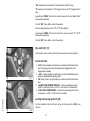
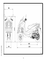
1
GILERA WOULD LIKE TO THANK YOU
for choosing one of its products. We have prepared this manual to help you to get the very best from your scooter. Please read it carefully before riding
the scooter for the first time. It contains information, tips and precautions for using your scooter. It also describes features, details and devices to assure
you that you have made the right choice. We believe that if you follow our suggestions, you will soon get to know your new vehicle and it will serve you
well for a long time to come. This booklet forms an integral part of the scooter; should the scooter be sold, it must be transferred to the new owner.
Fuoco 500ie
Ed. 2
The instructions given in this manual are intended to provide a clear, simple guide to using your scooter; this booklet also details routine maintenance
procedures and regular checks that should be carried out on the vehicle at an authorised Dealer or Service Centre. The booklet also contains
instructions for simple repairs. Any operations not specifically described in this manual require the use of special tools and/or particular technical
knowledge: to carry out these operations refer to any authorised Dealer of Service Centres.
2
Personal safety
Failure to completely observe these instructions will result in serious risk of personal
injury.
Safeguarding the environment
Sections marked with this symbol indicate the correct use of the vehicle to prevent damaging the environment.
Vehicle intactness
The incomplete or non-observance of these regulations leads to the risk of serious
damage to the vehicle and sometimes even the invalidity of the guarantee.
The signs that you see on this page are very important. They are used to highlight those
parts of the booklet that should be read with particular care. As you can see, each sign
consists of a different graphic symbol, making it quick and easy to locate the various
topics.
3
4
INDEX
VEHICLE......................................................................................
Dashboard................................................................................
Analogue instrument panel.......................................................
Clock.........................................................................................
Digital lcd display......................................................................
Maintenance icons................................................................
*MODE* button......................................................................
Key switch.................................................................................
Locking the steering wheel....................................................
Releasing the steering wheel................................................
Switch direction indicators........................................................
Horn button...............................................................................
Light switch...............................................................................
Emergency flashing light button................................................
Start-up button..........................................................................
Engine stop button....................................................................
Front suspension unlock-lock switch........................................
The immobilizer system............................................................
Keys......................................................................................
Immobilizerdevice enabled indicator led...............................
Operation...............................................................................
Programming the immobilizer system...................................
Saddle opening remote control.................................................
Remote control programming................................................
Accessing the fuel tank.............................................................
Power supply socket.................................................................
The saddle................................................................................
Opening the saddle to access the helmet compartment by
remote control.......................................................................
Opening the saddle...............................................................
Identification..............................................................................
Bag clip.....................................................................................
USE..............................................................................................
7
9
11
12
12
13
13
14
14
15
15
16
16
16
17
17
17
18
18
19
19
20
21
22
23
24
24
Checks......................................................................................
Refuelling..................................................................................
Tyre pressure............................................................................
Shock absorbers adjustment....................................................
Running in.................................................................................
Starting up the engine...............................................................
Precautions...........................................................................
Difficult start up.........................................................................
Stopping the engine..................................................................
anello antifurto..........................................................................
Stand.........................................................................................
Automatic transmission.............................................................
Safe driving...............................................................................
Front suspension locking system..............................................
MAINTENANCE...........................................................................
Engine oil level..........................................................................
Engine oil level check............................................................
Engine oil top-up...................................................................
Warning light (insufficient oil pressure).................................
Engine oil change..................................................................
Hub oil level..............................................................................
Tyres.........................................................................................
Spark plug dismantlement........................................................
Removing the air filter...............................................................
Air filter cleaning.......................................................................
Cooling fluid level......................................................................
Checking the brake oil level......................................................
Braking system fluid top up...................................................
Battery.......................................................................................
Use of a new battery.............................................................
Long periods of inactivity..........................................................
Fuses........................................................................................
Front light group........................................................................
24
25
26
26
27
5
28
28
30
31
32
33
35
35
36
36
37
37
37
40
45
46
46
46
46
47
48
50
51
52
52
53
55
55
57
57
58
58
63
Headlight adjustment.............................................................
Front direction indicators...........................................................
Rear optical unit........................................................................
Rear turn indicators...................................................................
Number plate light.....................................................................
Helmet compartment lighting bulb............................................
Rear-view mirrors......................................................................
Front and rear disc brake..........................................................
Puncture....................................................................................
Periods of inactivity...................................................................
Cleaning the vehicle..................................................................
TECHNICAL DATA......................................................................
Kit equipment............................................................................
SPARE PARTS AND ACCESSORIES........................................
Warnings...................................................................................
PROGRAMMED MAINTENANCE...............................................
Scheduled maintenance table...................................................
64
67
68
68
69
69
69
70
71
71
72
77
82
83
84
87
88
6
Fuoco 500ie
Chap. 01
Vehicle
7
1 Vehicle
01_01
8
A = Ignition key-switch
B = Hand brake
C = Bag hook
D = HAZARD button
E= Horn button
F = Turn indicator switch
G = Rear brake lever
H = Light switch + PASSING
I = Analogue instrument panel
L = Digital instrument panel
M = Warning light unit
N = RUN/OFF switch
O = Front brake lever
P = Throttle grip
Q= Front suspension locking-unlocking switch
R = Starter button
S = Mode button
9
1 Vehicle
Dashboard (01_01)
1 Vehicle
01_02
10
A = Immobilizer / antitheft LED
B= Speedometer with twin scale (Km/h and Mph)
C = CLOCK switch
D = Digital display
E = Front suspension locking system warning light
F= SET switch
G = Rpm indicator
H = Fuel gauge
I = Warning light for helmet compartment courtesy light on
L = Engine control telltale light and injection system failure warning light
M = Low fuel warning light
N = Engine stop warning light
O= Turn indicator warning light
P = Low oil pressure warning light
Q = Front suspension locking system failure warning light
R = Warning light for parking brake engaged
S = High-beam warning light
11
1 Vehicle
Analogue instrument panel (01_02)
Clock (01_03)
Pushing the «CLOCK» button for less than 1 second displays the following sequence:
• TIME
• DATE
To set the clock push and hold the «CLOCK» button longer than 3 seconds.
The numbers showing the hours will begin flashing.
Set the hour using the «SET» button. Push the «CLOCK» button again and the minutes numbers start flashing.
01_03
Set the minutes using the «SET»button. Push the «CLOCK» button again and the day
numbers start flashing.
Set the day with the «SET» button. Push the «CLOCK» button again and the month
numbers start flashing.
Set the month with the «SET» button. Push the «CLOCK» button again and the year
numbers start flashing.
Set the year with the «SET» button. Press the «CLOCK » button again for 4 seconds
to exit the adjustment menu.
During the reset process, not pressing any buttons for a period longer than 8 seconds
ends the process automatically and the display shows the modified time.
Digital lcd display (01_04)
A = Total odometer gauge
B = «BELT» maintenance icon
C = «SERVICE» maintenance icon
1 Vehicle
D = Engine coolant temperature indicator
E = Trip odometer (A-B) and ambient temperature gauge (selected with the MODE
button)
01_04
F = TIME-DATE indicator
12
H = Trip odometer gauge (B)
I = Trip odometer gauge (A)
L = Kilometre - mile indicator
M = «SET» button
N = «CLOCK» button
01_05
Maintenance icons
The icons signal the user that scheduled maintenance operations should be carried
out. A flashing «SERVICE» icon signals the need to carry out the scheduled maintenance service. A flashing «BELT» icon signals the driving belt needs replacing. In any
case, vehicle maintenance must be carried out at the kilometre service intervals recommended in this booklet.
WARNING
REFER TO THE «SCHEDULED MAINTENANCE TABLE» FOR FURTHER MAINTENANCE OPERATIONS
01_06
*MODE* button (01_05, 01_06)
Pushing the ''MODE'' «S» button for less than a second displays the following sequence of functions:
1. Trip odometer «A»
2. Trip odometer «B»
3. Ambient temperature «°»
Push the ''MODE'' «S» button for longer than 3 seconds to zero set the trip odometer.
UNIT OF MEASUREMENT SETTING
Press and hold the "MODE" «S» button for at least 3 seconds and at the same time
turn the ignition key to "on".
The icons "kmi" and "°E" will start flashing.
13
1 Vehicle
G = Low fuel warning light
"Kmi" represents the combination of "km" (kilometres) and "mi" (miles)
"°E" represents the combination of "°C" (degrees Celsius) and "°F" (degrees Fahrenheit).
By pushing the "MODE" «S» button for less than a second, the icons "km" and "mi"
are selected sequentially.
Push the "SET" button «M» to confirm the selection.
Now the ambient temperature icon "°C" or "°F" starts flashing.
By pushing the "MODE" «S» button for less than a second, the icons "°C" and "°F"
are selected sequentially.
Push the "SET" button «M» to confirm the selection.
Key switch (01_07)
The key switch «A» is located on the front knee-guard panel near the bag hook.
SWITCH POSITIONS
1 Vehicle
01_07
1. LOCK = Ignition disabled, extractable key, mechanical antitheft device enabled. The parking brake cannot be released when engaged and can be
engaged when released.
2. « OFF » = Ignition disabled, extractable key, mechanical antitheft device disabled and enabled/disabled parking brake.
3. ON = Ready to start, non-extractable key, mechanical antitheft device disabled.
4. «HELMET COMPARTMENT OPENING» = Helmet compartment opening
position. Press the key when in «OFF» or «ON» and turn it anticlockwise.
5. «FUEL TANK COVER OPENING» = Fuel tank cover opening position. Press
the key when in «OFF» or «ON» and turn it clockwise.
Locking the steering wheel (01_08)
Turn the handlebar to the left as far as it will go; turn the key «B» to «LOCK » and
remove it.
01_08
14
DO NOT TURN THE KEY TO «LOCK» OR «OFF» WHILE RIDING.
Releasing the steering wheel
Reinsert the key «B» and turn it to «KEY OFF».
CAUTION
DO NOT TURN THE KEY TO «LOCK» OR «OFF» WHILE RIDING.
Switch direction indicators (01_09)
Lever «F» towards «1» = left turn indicators switched on;
Lever «F» towards «2» = right turn indicators switched on;
The lever «F» automatically returns to «0 » and the turn indicators remain on; push
the lever «F» to turn them off.
01_09
15
1 Vehicle
CAUTION
Horn button (01_10)
Push the button «E» to sound the horn.
01_10
Light switch (01_11)
When the light switch «H» is set to «0», the low-beam light is on. When set to «1»,
the high-beam light is activated. If the light switch «H» is pressed when set to «2», the
high-beam light is activated. The switch goes back to «0» automatically.
When the ignition key is set to «ON» and the vehicle is not running, only the tail light
is on.
01_11
When the ignition key is set to «ON» and the vehicle is running, the low-beam lights
will turn on two seconds after the ignition; when the high-beam lights turn on, the lowbeam lights turn off.
Emergency flashing light button (01_12)
1 Vehicle
It enables the activation of the 4 turn indicators simultaneously. The control «D» can
be enabled only with the key set to «ON», but once enabled, it keeps functioning even
if the key is set to «OFF» or «LOCK». To disable this function, simply turn the key
switch to «ON».
01_12
16
To start the engine, press the starter button «R» after pulling one of the two brake
levers.
If the rider is not on the vehicle, the suspension lock will start the engine at idling speed.
01_13
Engine stop button (01_14)
The engine can be started when the emergency cut-off switch «N» is set to «1»
RUN; if the emergency cut-off switch «N» is set to «0» OFF , the engine cannot be
started or it shuts off if already running.
CAUTION
01_14
DO NOT OPERATE THE ENGINE STOP SWITCH "N" WHILE RIDING UNLESS
THERE IS AN EMERGENCY.
Front suspension unlock-lock switch (01_15)
The «Q» switch engages and disengages the front suspension locking system.
As the topic is so complex, find the instructions for using this control in the Use chapter.
01_15
17
1 Vehicle
Start-up button (01_13)
The immobilizer system
In order to enhance theft protection, the scooter is equipped with a «PIAGGIO IMMOBILIZER » electronic engine locking device that is activated automatically when
the starter key is removed. Upon start-up, the «PIAGGIO IMMOBILIZER» system
checks the starter key, and only if this key is recognised will the immobilizer system
allow the scooter to be started.
Keys (01_16, 01_17, 01_18)
Two types of keys come with the vehicle.
01_16
The key «A» is the «MASTER» key.
Only a single copy of this key is supplied, which is necessary to program all your other
keys and for your dealer to perform some maintenance operations. For this reason it
is advised that it be used only in exceptional circumstances.
The key «B» (single copy supplied) is used for regular operations such as:
- Engine start-up.
- Remote control saddle opening.
01_17
Together with the two keys, you will be given a CODE CARD bearing the same code
imprinted onto the two keys.
WARNING
1 Vehicle
LOSING THE RED KEY PREVENTS ANY REPAIRS OF THE "PIAGGIO IMMOBILIZER" SYSTEM AND THE ENGINE CONTROL UNIT.
01_18
18
KEEP THE "CODE CARD" AND THE RED HANDGRIP KEY IN A SAFE PLACE
(NOT ON YOUR VEHICLE).
Immobilizerdevice enabled indicator led (01_19)
01_19
Activation of the "PIAGGIO IMMOBILIZER" system is signalled by a flashing «A»
indicator. In order to reduce battery discharge, the indicator LED turns off automatically
after 48 hours of uninterrupted functioning. Should the system fail, different LED flashing patterns will provide the Authorised Service Centre with information on the type
of fault detected.
Operation
Each time the starter key «B» is removed while in the «OFF», or «LOCK» position,
the protection system activates the engine lock. Turning the key to "ON" disables the
engine lock, provided that the safety system recognises the code transmitted by the
key. If the code is not recognised, turn the key first to "OFF" and then to "ON"; if lock
persists, try again using the «A» MASTER key. If the engine cannot be started, contact
an Authorised Service Centre, which is provided with the electronic equipment required to detect and repair the system.
When supplementary keys are required, remember that the programming must be
performed on all the keys whether they are new or existing ones.
Contact an Authorised Service Centre and bring the «A» MASTER key and all
«B» starter keys that you own.
The codes of keys not submitted for the new storage procedure are deleted from the
memory. Any lost keys will therefore not be enabled to start the engine.
19
1 Vehicle
WARNING
WARNING
EACH KEY HAS ITS OWN AND UNIQUE CODE, WHICH MUST BE STORED BY
THE SYSTEM CONTROL UNIT.
VIOLENT SHOCKS MAY AFFECT THE ELECTRONIC COMPONENTS OF THE
KEY.
IF THE VEHICLE IS SOLD, THE MASTER-HANDGRIP KEY (AS WELL AS THE
OTHER STARTER KEYS) AND THE "CODE CARD" MUST ALSO BE TRANSFERRED TO THE NEW OWNER.
Programming the immobilizer system
Below is described the procedure to follow for programming the PIAGGIO IMMOBILIZER system and/or for storing other key codes. The programming procedure should
be carried out with the engine stop switch set to «RUN».
START PROCEDURE
Insert the «MASTER» key into the switch (in "OFF" position), turning it to «ON» position. After 1 - 3 seconds, turn the key to "OFF" again and pull it out.
INTERMEDIATE STAGE
After extracting the «MASTER» key, insert, within ten seconds, the key that is going
to be programmed and turn it immediately to «ON» position. After 1-3 seconds, turn
the key to "OFF" again and pull it out. In this way, a maximum of 7 keys can be programmed by repeating the above procedure and keeping the indicated times.
1 Vehicle
FINAL STAGE
After extracting the key to be programmed, insert the «MASTER» key again and turn
it to «ON» position (perform this operation within the ten seconds following the ex-
20
CORRECT PROGRAMMING CHECK PHASE
Insert the «MASTER» key, disabling the transponder (i.e., by tilting the key cap by
90°), and turn the key to «ON» position. Perform the engine start-up operation. Ensure
that the engine does not start. Insert the programmed key and repeat the start-up
operation. Check that engine starts.
WARNING
SHOULD YOU STAR THE ENGINE WITH THE MASTER KEY (WITH TRANSPONDER OFF) OR IN THE EVENT OF WRONG OPERATION DURING PROGRAMMING, REPEAT THE PROCEDURE FROM THE BEGINNING.
Saddle opening remote control (01_20)
01_20
The scooter is fitted with a remote control to open the saddle. This remote control is
supplied together with the keys and it has been programmed to control the opening
device control unit at the manufacturing stage. If the remote control is lost, a new one
can be requested and programmed at any Authorised Service Centre. The remote
control is powered by inner batteries that get discharged after extended used; If the
green LED turns on when the button is pressed, the remote control is working properly.
You may need to replace the batteries if the remote control fails or if its range of
operation is reduced. To separate the two halves of the remote control, insert the blade
of a plain slot screwdriver at one point on the edge and slide it all around. When the
remote control is open, remove the two batteries from the contact terminal. Install the
two new CR1616 3V batteries with the positive pole facing the contact terminal.
Reassemble the remote control by pressing the two clip-on halves gently with your
fingers.
To open the saddle without the remote control, follow the procedure described in the
«Emergency Saddle Opening» section.
21
1 Vehicle
traction of the previous key). Leave it in this position for 1 to 3 seconds and return it
to the «OFF» position.
Remote control programming
Follow these steps to program the remote controls:
1. Insert the remote control key to be programmed in the steering lock key block.
2. Turn the key to «ON», press the button on the remote control, release the button,
turn the key back to «OFF» from the «ON» position, all within 4 seconds.
3 Wait 1 to 8 seconds.
4. Repeat steps 2 and 3 for 4 times without removing the key.
The control unit confirms the programming has been successfully executed by opening the saddle.
WARNING
TO STORE THE OTHER REMOTE CONTROLS TO MEMORY, (MAXIMUM 8), YOU
NEED TO REPEAT THE WHOLE PROCEDURE AGAIN. FAILURE TO CARRY OUT
THESE OPERATIONS WITHIN THE INDICATED TIMES WILL RESULT IN THE
AUTOMATIC CANCELLATION OF THE PROCESS FOR PROGRAMMING THE
REMOTE-CONTROLLED KEYS.
WARNING
1 Vehicle
AVOID PRESSING THE REMOTE CONTROL BUTTON MORE THAN ONCE WHEN
FAR AWAY FROM THE SCOOTER. THE SYNCHRONISM BETWEEN THE REMOTE CONTROL AND THE RECEIVER CAN BE IMPAIRED. SHOULD THIS BE
THE CASE, REPEAT THE PROGRAMMING PROCEDURE. DO NOT KEEP THE
REMOTE CONTROL IN PLACES WITH TEMPERATURES EXCEEDING 60° C THE
BATTERY WILL RUN DOWN TOO QUICKLY.
22
TO AVOID BATTERY DISCHARGE, THE SADDLE OPENING REMOTE CONTROL
RADIO RECEIVER DEACTIVATES 7 DAYS AFTER THE LAST TIME THE VEHICLE
WAS SHUT OFF.
JUST TURN THE KEY TO «ON» TO REACTIVATE THE RECEIVER.
Accessing the fuel tank (01_21, 01_22)
To open the fuel tank cover, set the key to «OFF» or « ON», then press and turn it
clockwise.
01_21
01_22
23
1 Vehicle
WARNING
Power supply socket (01_23)
There is a plug socket "D" inside the helmet compartment.
The plug socket may be used for external consumers (mobile phone, inspection light,
etc.).
CAUTION
01_23
PROLONGED USE OF THE PLUG SOCKET MAY RESULT IN PARTIAL DISCHARGE OF THE BATTERY
Electric characteristic
Plug socket
12 V - 180 W MAX
The saddle (01_24, 01_25)
The saddle is supplied with a protection cover which may be used in case of rain.
Lift the saddle and extract the cover from its housing, then extend it over the whole
length of the saddle, starting from the front-end; do not over stretch the cover to avoid
tearing the material; close the saddle.
CAUTION
01_24
1 Vehicle
DO NOT USE THE VEHICLE WITHOUT THE PROTECTION COVER.
Opening the saddle to access the helmet compartment by
remote control (01_26)
When the key is in «LOCK» or «OFF» position you can open the saddle using the
remote control. The saddle cannot be opened only when the key is set to "ON".
24
OBJECTS INAPPROPRIATELY ARRANGED INSIDE THE HELMET COMPARTMENT MAY DEFORM THE SADDLE CAUSING THE COURTESY LIGHT TO REMAIN ON AND THIS WILL DISCHARGE THE BATTERY. IN ANY CASE, THE
WARNING LIGHT "I" ON THE INSTRUMENT PANEL SIGNALS IF THE LIGHT IS
ON OR OFF.
01_25
WARNING
THE REMOTE CONTROL OPERATES WITHIN A DISTANCE OF ABOUT 3/5 METRES WITH FULLY CHARGED BATTERIES. WHEN YOU ARE NEAR THE
SCOOTER, HANDLE THE REMOTE CONTROL CAREFULLY SO AS TO AVOID
UNINTENTIONAL OPENING OF THE SADDLE. REFER TO THE «OPENING THE
SADDLE WITH REMOTE CONTROL» SECTION TO REPLACE BATTERIES.
Opening the saddle (01_27)
01_26
With the key set to «ON» or «OFF», press it and turn it anticlockwise.
01_27
25
1 Vehicle
WARNING
Identification (01_28, 01_29)
Identification registration numbers are made up of a prefix and a number stamped on
the chassis and on the engine. These numbers must always be quoted when ordering
spare parts. We recommend checking that the chassis registration number stamped
on the vehicle corresponds with that on the vehicle documentation.
CAUTION
01_28
BE REMINDED THAT ALTERING IDENTIFICATION REGISTRATION NUMBERS
CAN LEAD TO SERIOUS PENAL SANCTIONS (IMPOUNDING OF THE VEHICLE,
ETC.).
Chassis number
To read the chassis number, remove the lid «A» in the helmet compartment.
Engine number
01_29
The engine number «B» is stamped near the rear left shock absorber lower support.
Bag clip (01_30)
1 Vehicle
To use the bag hook «C» mounted on the counter shield, pull it slightly towards the
back part of the vehicle.
01_30
26
Fuoco 500ie
Chap. 02
Use
27
Checks
Before using the vehicle, check:
1. There is enough fuel in the fuel tank.
2. The correct fluid level for front and rear brakes.
3. That tyres are properly inflated.
4. The correct functioning of tail lights, headlamp, turn indicators, stop light and license
plate light.
5. The correct functioning of front and rear brakes.
6. The oil level in the gearcase.
7. The engine oil level.
8. The coolant level.
Refuelling (02_01, 02_02)
Fuel: Open the access door to the fuel tank cap and remove the cap«T».
Recommended fuel: Unleaded petrol, min octane rating of 95. The instrument «H»
indicates the fuel level and the warning light «M» indicates the reserve.
WARNING
02_01
SWITCH OFF THE ENGINE BEFORE REFUELLING WITH PETROL.
PETROL IS HIGHLY INFLAMMABLE.
DO NOT SMOKE AND KEEP OPEN FLAMES AT A DISTANCE:FIRE HAZARD.
2 Use
DO NOT INHALE FUEL FUMES.
DO NOT ALLOW PETROL TO COME INTO CONTACT WITH HOT ENGINE OR
ANY PLASTIC PARTS.
28
2 Use
CAUTION
PETROL DAMAGES THE PLASTIC PARTS OF THE BODYWORK.
WARNING
02_02
DO NOT RIDE WITH THE FUEL TANK ALMOST EMPTY, LACK OF FUEL CAN
DAMAGE THE CATALYTIC CONVERTER.
CAUTION
USING NON-RECOMMENDED PETROL REDUCES THE EFFICIENCY OF THE
EXHAUST AND FUEL SUPPLY SYSTEMS.
CAUTION
DO NOT USE THE VEHICLE TO THE COMPLETE EXHAUSTION OF THE FUEL;
IN THE EVENT THAT THIS SHOULD OCCUR, DO NOT ATTEMPT TO START THE
ENGINE. TURN THE KEY SWITCH TO OFF AND TOP-UP THE TANK AS SOON
AS POSSIBLE. FAILURE TO FOLLOW THESE GUIDELINES COULD DAMAGE
THE FUEL PUMP AND/OR THE CATALYTIC CONVERTER.
WARNING
IT IS HIGHLY INADVISABLE TO REFUEL USING METHODS OTHER THAN NORMAL FUEL PUMPS. IF PETROL IS NOT COMPLETELY CLEAN, IT CAN DAMAGE
THE FUEL SUPPLY SYSTEM FILTERS.
29
CAUTION
USING OILS OTHER THAN THOSE RECOMMENDED CAN SHORTEN THE LIFE
OF THE ENGINE.
Characteristic
Fuel tank (reserve)
~ 12 l (~2 l)
Tyre pressure (02_03)
Check the tyre pressure and wear periodically (roughly every 500 km). Tyres feature
wear indicators; replace tyres as soon as these indicators become visible on the tyre
tread. Also check that the tyres do not show signs of splitting at the side or irregular
tread wear; if this occurs, go to an authorised workshop or at least to a workshop
equipped to perform the replacement.
CAUTION
02_03
TYRE PRESSURE SHOULD BE CHECKED WHEN TYRES ARE COLD.INCORRECT TYRE PRESSURE CAUSES ABNORMAL TYRE WEAR AND MAKES RIDING DANGEROUS.
2 Use
TYRES MUST BE REPLACED WHEN THE TREAD REACHES THE WEAR LIMITS
SET FORTH BY LAW.
TYRES
Front tyre
Tubeless 120/70-12" 51S or 51P
30
Tubeless 140/70 - 14" 68S or 68P
reinf
2 Use
Rear tyre
TYRE INFLATION PRESSURE
Front tyre pressure (with
passenger)
1.6 bar (1.8 bar)
Rear tyre pressure (with
passenger)
2.4 bar (2.6 bar)
Shock absorbers adjustment (02_04, 02_05)
The preloading of the springs can be adjusted to 4 positions using the ring nut located
in the lower part of the shock absorbers and the specific spanner supplied.
Position 1: minimum preload: driver only
Position 2 medium preloading: driver only
Position 3 medium preloading: rider and passenger
Position 4: maximum preloading: driver, passenger, and luggage.
02_04
In order to carry out this operation you will need to use the specific spanner in the kit.
Spring preloading increases by turning the ring nut towards «A», but decreases if the
ring nut is turned towards «B».
CAUTION
RIDING THE VEHICLE WITH THE SPRING PRELOADING NOT CORRECTLY SET
FOR THE RIDER AND POSSIBLE PASSENGER, COULD REDUCE THE COMFORT OF THE RIDE AND THE PRECISION OF THE STEERING.
02_05
31
WARNING
WE RECOMMEND WEARING GLOVES WHILE CARRYING OUT THIS OPERATION IN ORDER TO AVOID INJURIES.
WARNING
WE STRONGLY RECOMMEND NOT TO ADJUST BOTH SHOCK ABSORBERS
WITH DIFFERENT PRELOADING
Running in
DURING THE FIRST 1000 KM DO NOT RIDE THE VEHICLE OVER 80% OF ITS
MAX. SPEED. AVOID OPENING THE THROTTLE GRIP COMPLETELY OR KEEPING A CONSTANT SPEED ALONG LONG SECTIONS OF ROAD. AFTER THE
FIRST 1000 KM INCREASE SPEED PROGRESSIVELY, IF POSSIBLE, UNTIL THE
MAXIMUM PERFORMANCE IS OBTAINED.
CAUTION
2 Use
IN ORDER TO AVOID DAMAGING THE VEHICLE, PLEASE COMPLY WITH THE
RULES LISTED ABOVE.
32
The vehicle is supplied with an ignition cut-off system, activated by the emergency
cut-off switch. The engine cannot be started if the ignition cut-off switch is in the OFF
position
A running engine automatically switches off when the ignition cut-off switch is set to
OFF.
02_06
The vehicle is equipped with automatic transmission with direct drive, so that starting
is effected by turning the throttle grip to idle speed; to start-off from stationary position,
progressively twist the throttle grip. The vehicle is equipped with an electrical fuel
pump that switches on automatically as soon as the engine is started. The vehicle has
a front suspension locking system; a sensor placed under the saddle will prevent the
vehicle riding, but not its starting-up, if the rider is not seated in riding position.
To start-up the engine:
1. Rest the vehicle on its centre-stand, ensuring the rear wheel is not touching the
ground.
2. Maintain the throttle grip "P" completely untwisted.
3. Insert the key into the ignition switch «A» and turn it onto the ON position.
02_07
4. Make sure that the «N» switch is set to the RUN position.
5. Pull either the front «O» or rear «G» brake lever, while pressing the starter button
«R».
WARNING
THE AUTOMATIC TRANSMISSION MAKES THE REAR WHEEL TURN EVEN
WHEN THE THROTTLE IS SLIGHTLY TWISTED. RELEASE THE BRAKE CAREFULLY AFTER STARTING, AND THEN ACCELERATE GRADUALLY.
02_08
33
2 Use
Starting up the engine (02_06, 02_07, 02_08)
CAUTION
DO NOT START-UP THE ENGINE IN CLOSED AREAS BECAUSE EXHAUST
GASES ARE TOXIC.
CAUTION
DUE TO THE HIGH TEMPERATURES THE CATALYTIC CONVERTER CAN
REACH, ALWAYS TAKE CARE, WHEN PARKING THE SCOOTER, THAT THE
EXHAUST DOES NOT COME INTO CONTACT WITH FLAMMABLE MATERIALS,
TO AVOID SERIOUS BURNS.
CAUTION
DO NOT SWITCH OFF THE ENGINE WHILE THE VEHICLE IS MOVING. UNBURNED FUEL COULD ENTER THE CATALYTIC CONVERTER AND BURN,
CAUSING IT TO OVERHEAT AND POSSIBLY DESTROYING IT.
CAUTION
2 Use
NEITHER PUSH THE STARTER BUTTON NOR TURN THE KEY SWITCH TO «ON»
WHEN THE TANK IS EMPTY SINCE THE START-UP SYSTEM MAY GET DAMAGED.
34
2 Use
WARNING
NEVER TRY TO START-UP THE ENGINE WITH THE THROTTLE GRIP TWISTED.
THIS MAY LEAD TO LOSING CONTROL OF THE VEHICLE AND TO ROLLOVER,
WITH CONSEQUENT SERIOUS OR, IN SOME CASES, LETHAL INJURIES.
Precautions
CAUTION
NEVER STRESS THE ENGINE AT LOW TEMPERATURES IN ORDER TO AVOID
POSSIBLE DAMAGE. BE CAREFUL NEVER TO EXCEED THE MAXIMUM SPEED
WHILE RUNNING DOWNHILL, IN ORDER TO AVOID DAMAGING THE ENGINE.
IN ANY CASE, IN ORDER TO PRESERVE THE ENGINE FROM PROLONGED EXCESSIVE REVOLUTIONS, THE REVOLUTION LIMITER WILL BE ACTIVATED IF
THE ENGINE SPEED EXCEEDS THE ESTABLISHED THRESHOLD.
WARNING
AFTER A LONG DISTANCE COVERED AT THE MAXIMUM SPEED, DO NOT STOP
THE ENGINE IMMEDIATELY, BUT LET IT RUN AT IDLE FOR A FEW SECONDS.
Difficult start up
In the rare case of flooding the engine, to facilitate start-up, it is possible to try to put
the vehicle into action with the gas hand grip partially or completely open. It is however
necessary, once the engine is started, to take your vehicle to an Authorised Service
Centre to determine the cause of this problem and to re-establish the vehicle proper
functioning.
35
Stopping the engine (02_09)
Fully untwist the throttle grip, then rotate the key in the switch «A » to «KEY
OFF» (extractable key).
CAUTION
02_09
DUE TO THE HIGH TEMPERATURES THE CATALYTIC CONVERTER CAN
REACH, ALWAYS TAKE CARE, WHEN PARKING THE SCOOTER, THAT THE
EXHAUST DOES NOT COME INTO CONTACT WITH FLAMMABLE MATERIALS,
TO AVOID SERIOUS BURNS.
CAUTION
DO NOT SWITCH OFF THE ENGINE WHILE THE VEHICLE IS MOVING. UNBURNED FUEL COULD ENTER THE CATALYTIC CONVERTER AND BURN,
CAUSING IT TO OVERHEAT AND POSSIBLY DESTROYING IT.
anello antifurto (02_10)
The «D» ring on the right side of the vehicle is used to fasten the vehicle to an object
using a scooter chain. Do not use the ring for other purposes.
WARNING
2 Use
02_10
THIS ACCESSORY IS NOT A THEFT PREVENTION GUARANTEE, IT IS ONLY A
DETERRENT.
36
Push with your foot on the centre stand's fork "F" while lifting the vehicle backward,
holding onto the handlebar.
02_11
Automatic transmission
To ensure simple, pleasurable riding, the vehicle is equipped with automatic transmission with regulator and centrifugal clutch. The system is designed to provide the
best performance (acceleration and consumption) while riding on both flat roads and
uphill.
If you have to stop on an uphill slope (traffic lights, traffic jam, etc.) use only the brake
to keep the vehicle still, leaving the engine running at idle speed. Using the
engine to keep the vehicle still can cause the clutch to overheat, due to the
friction of the clutch masses against the capstan. Besides, avoid accelerating
with the hand brake engaged. It is therefore recommended to avoid conditions of
prolonged clutch slippage (besides those previously indicated) like driving uphill fully
laden on steep slopes or starting off with driver and passenger at slopes greater than
25%.
Observe the following precautions if the clutch overheats:
1. Do not continue riding in such conditions.
2. Let the clutch cool down with the engine at idle speed for a few minutes.
Safe driving
Some simple tips are provided below that will enable you to use your vehicle on a daily
basis, confidently and safely. Your skill and your mechanical knowledge are the basis
37
2 Use
Stand (02_11)
of safe riding. We recommend practising riding in traffic-free zones, in order to acquire
a good knowledge of your vehicle.
1. Before riding off, remember to put on your helmet and fasten it correctly.
2.Reduce speed on rough roads and drive with care.
3. After riding on a long stretch of wet road without using the brakes, braking can be
poor at the beginning. Given these conditions, it is a good idea to operate the brakes
from time to time.
4. Avoid setting off by mounting the vehicle while it is resting on the support. In any
case, the rear wheel should not be turning when in comes into contact with the ground,
in order to avoid abrupt departures.
5. If driving over roads affected by sand, mud, snow mixed with salt, etc., we recommend cleaning the brake disc with a non-corrosive detergent frequently in order to
prevent corrosive particles from building up in the holes, which may cause early break
pad wear.
CAUTION
ALWAYS RIDE WITHIN YOUR LIMITS RIDING UNDER THE INFLUENCE OF ALCOHOL OR OTHER DRUGS AND CERTAIN MEDICATIONS IS EXTREMELY DANGEROUS.
CAUTION
2 Use
IN ORDER TO PREVENT ANY ACCIDENTS RIDE VERY CAREFULLY AFTER
ADDING ACCESSORIES AND WHILE CARRYING LUGGAGE. ADDING ACCESSORIES AND LUGGAGE CAN REDUCE THE VEHICLE'S STABILITY, PERFORMANCE AND SAFETY DURING USE.
38
2 Use
WARNING
NEVER RIDE THE VEHICLE WITH ADDED ACCESSORIES (CASE AND/OR
WINDSHIELD) FASTER THAN 120 KM/H. WITHOUT THESE ACCESSORIES THE
VEHICLE MAY BE DRIVEN AT A HIGHER SPEED WITHIN THE LEGAL LIMITS. IF
THERE ARE NOT-PIAGGO ACCESSORIES FITTED, OR AN ABNORMAL LOAD,
OR IF THE VEHICLE IS NOT IN A GENERALLY GOOD CONDITION, OR WHENEVER WEATHER CONDITIONS DEMAND IT, SPEED SHOULD BE FURTHER
REDUCED.
CAUTION
DO NOT ADJUST THE MIRRORS WHILE RIDING. THIS COULD CAUSE YOU TO
LOOSE CONTROL OF THE VEHICLE.
CAUTION
ANY CHANGES TO THE VEHICLE PERFORMANCE AS WELL AS ALTERATIONS
TO ORIGINAL STRUCTURAL PARTS IS STRICTLY FORBIDDEN BY LAW, AND
RENDERS THE VEHICLE NO LONGER CONFORMING TO THE APPROVED TYPE
AND DANGEROUS FOR RIDING.
39
Front suspension locking system (02_12, 02_13, 02_14, 02_15,
02_16, 02_17)
The front suspension locking system simply prevents vehicle tilting when the «Q»
switch is pressed.
The warning light «E» starts flashing when the key switch is set to «ON». This means
that the system is enabled for locking activation.
02_12
When the «Q» switch is turned to «1», a continuous sound alarm signals that the
locking system is engaged and, at the same time, the warning light «E» turns on
steadily.
When the «Q» switch is turned to «2» , an intermittent sound alarm signals that the
locking system is disengaged and, at the same time, the warning light «E» starts
flashing again. Warning light «E » turns off when riding starts. This means that the
system allows for vehicle tilting.
Engaging tilt locking is possible only if the following conditions occur at the same time:
•
•
•
•
02_13
Throttle completely untwisted
Engine rpm below 2500 rpm
Vehicle speed below 10 km/h
Locking system WARNING light «C» off (the system has not detected failures)
If one of these conditions is not checked, the warning light «E » remains off and locking
cannot be engaged (in normal riding conditions, the warning light «E» is off).
With engine on, system locked and warning light «E» on, the suspension locking system is disengaged automatically and the warning light «E » turns off when the throttle
is twisted to start the ride.
2 Use
02_14
For riders' safety, the vehicle has a rider detection sensor in the saddle which enables the system to prevent vehicle motion and suspension unlocking (in case of locked
suspension) when the rider is not properly seated in riding position: in such case, the
WARNING light «C» turns on steadily
40
2 Use
CAUTION
THE RIDER DETECTION SENSOR IS LOCATED IN THE FRONT PART OF THE
SADDLE. AVOID PLACING BAGS OR HEAVY OBJECTS ACCIDENTALLY ON
THE SADDLE.
02_15
NOT OBSERVING THIS RULE MAY MOVE THE VEHICLE FORWARD AND RELEASE THE SUSPENSION LOCKING SYSTEM EVEN IF THE RIDER IS NOT
SEATED, BY SIMPLY TWISTING THE THROTTLE. THE VEHICLE COULD FALL
ACCIDENTALLY AS A CONSEQUENCE.
WARNING
EVERY TIME THE VEHICLE IS STOPPED, MAKE SURE THE FRONT SUSPENSION LOCKING SYSTEM IS ENGAGED. OTHERWISE, PLACE YOUR FEET ON
THE GROUND TO KEEP THE VEHICLE UPRIGHT.
WARNING
02_16
AVOID USING THE LOCKING SYSTEM WHEN RIDING THE VEHICLE ALONG IRREGULAR ROADS OR ROADS WITH OBSTACLES(E.G. ROAD HUMPS, SIDEWALK, ETC.).
IN CASE OF ENGINE FAILURE (DISCHARGED BATTERY) AVOID PULLING THE
VEHICLE WITH THE LOCKING SYSTEM ENGAGED.
WITH THE LOCKING SYSTEM ENGAGED AND THE ENGINE OFF, AVOID MOVING THE VEHICLE AT SPEEDS ABOVE 5 Km/h.
02_17
41
WARNING
IF THE RIDER IS NOT SEATED ON THE SADDLE WHILE THE VEHICLE IS IN
MOTION AND THE LOCKING SYSTEM IS ENGAGED, AVOID OPERATING THE
THROTTLE CONTROL PURPOSELESSLY AS THIS MAY DAMAGE THE CATALYTIC CONVERTER.
CAUTION
DO NOT RIDE DOWNHILL WITH THE SUSPENSION LOCKING SYSTEM ENGAGED AND THE KEY SWITCH SET TO OFF.
With the vehicle off and the suspension locking system engaged, it is possible to get
off the vehicle without using the stand. For safety reasons, it is recommended to press
the hand brake lever shown in the figure, moving it form position «A » to position
«B».
When the hand brake «B» is engaged, warning light «R» on the instrument panel turns
on.
When the hand brake is set to «B» and the key switch is turned to position «1», the
safety system that prevents the hand brake from getting released is activated. To
release the hand brake, turn the key switch to «2» or «3». If the switch is set to «1 » ,
the hand brake can also be engaged.
WARNING
2 Use
IT IS PREFERABLE TO USE THE STAND IF THE VEHICLE STOPS ON A STEEP
SLOPE.
ALWAYS OBSERVE THE CUSTOMARY SAFETY PRECAUTIONS FOR CASES
WHEN THE VEHICLE STOPS ON A STEEP SLOPE. TURN THE WHEELS SO
42
If the WARNING light «C» turns on (flashes), it means that there is a failure in the front
suspension locking system. Therefore, it is necessary to contact an Authorised Service Centre. If the front suspension is locked , it can be unlocked by operating the
«Q» switch twice quickly on the unlocking position «2». Once the suspension is unlocked, the vehicle can be normally used, except for the locking system which will be
disengaged.
For some cases of failure, the vehicle speed is auto-limited to 30 Km/h. This automatic
procedure is activated to enhance safety until the failure is eliminated.
Always contact an Authorised Service Centre.
If the continuous sound alarm is activated when the WARNING light «C» turns on
(steadily), try to unlock the system by operating the «Q» switch twice quickly to the
unlocking position «2». If it cannot be unlocked, contact an Authorised Service Centre.
43
2 Use
THAT THE POTENTIAL MOVEMENT CAUSED BY THE SLOPE TAKES THAT
WHEEL AGAINST THE SIDEWALK. WITH THE STEERING LOCK ENGAGED,
MANOEUVRE SO THAT THE SIDEWALK IS TO THE RIGHT WHEN YOUR VEHICLE IS PARKED UPHILL AND TO THE LEFT WHEN PARKED DOWNHILL.
44
2 Use
Fuoco 500ie
Chap. 03
Maintenance
45
Engine oil level
03_01
In 4T engines, engine oil is used to lubricate the distribution elements, main bearings
and thermal group. An insufficient quantity of oil can cause serious damage to
the engine itself. In all four-stroke engines, a loss of efficiency in oil performance and
consumption should be considered normal. Consumption can particularly reflect the
conditions of use (i.e. when driving at "full acceleration" all the time, oil consumption
increases). The replacement frequencies provided for by the maintenance programme
are defined, depending on the total contents of oil in the engine and average consumption measured following standardised methods. In order to prevent any problems, we recommend checking oil level more frequently than indicated in the
Scheduled Maintenance table or before setting off on long journeys. The vehicle
is, however, equipped with an oil pressure warning light on the instrument panel.
Engine oil level check (03_01, 03_02)
Every time the vehicle is used, visually inspect the level of the engine oil when the
engine is cold (after completely unscrewing the oil cap/dipstick). The oil level should
be somewhere between the MAX and MIN reference marks on the dipstick «A»; during
the oil check, the vehicle must be resting on its centre stand on an even, horizontal
surface.
03_02
If the check is carried out after the vehicle has been used, and therefore with a hot
engine, the level line will be lower; in order to carry out a correct check, wait at least
10 minutes after the engine has been stopped so as to get the correct level.
3 Maintenance
Engine oil top-up
Always check the oil level before carrying out top ups and add oil without exceeding
the MAX level. Getting an oil level between the MIN and MAX levels requires ~ 400
cm³ of oil. An oil check-up and top-up should be carried out at any Authorised Service
Centre, as indicated in the scheduled maintenance table.
03_03
Warning light (insufficient oil pressure)
The vehicle is equipped with a warning light that lights up when the key is turned to
the «ON». However, this light should switch off once the engine has been started. If
the light comes on while braking, at idle speed or while turning a corner, it is
46
Engine oil change (03_03, 03_04)
03_04
The oil and the filter must be changed as indicated in the scheduled maintenance table
at an Authorised Service Centre. The engine should be emptied by draining the oil
via the drainage tap «B» of the mesh filter on the transmission side. In order to facilitate
oil drainage, loosen the cap/dipstick «A». Unscrew and remove the oil cartridge filter
«C». Install a new oil filter taking care to lubricate the sealing O-rings with engine oil.
Since a certain quantity of oil still remains in the circuit, add approximately 1500 cm³
of oil through cap «A». Then start up the scooter, leave it running for a few minutes
and switch it off: after five minutes, check the level and if necessary, top-up without
exceeding the MAX. level. The cartridge filter must be replaced at every oil change.
For top-ups and oil changes, use new oil of the recommended type.
CAUTION
RUNNING THE ENGINE WITH INSUFFICIENT LUBRICATION OR WITH INADEQUATE LUBRICANTS ACCELERATES THE WEAR AND TEAR OF THE MOVING
PARTS AND CAN CAUSE IRRETRIEVABLE DAMAGE.
TOPPING UP THE ENGINE WITH AN EXCESSIVE AMOUNT OF OIL MAY CAUSE
MALFUNCTION AND/OR A DROP IN PERFORMANCE OF THE VEHICLE.
USING OILS OTHER THAN THOSE RECOMMENDED CAN SHORTEN THE LIFE
OF THE ENGINE.
CAUTION
USED OILS CONTAIN SUBSTANCES HARMFUL TO THE ENVIRONMENT. FOR
OIL REPLACEMENT, CONTACT AN AUTHORISED SERVICE CENTRE, WHICH
IS EQUIPPED TO DISPOSE OF USED OILS IN AN ENVIRONMENTALLY FRIENDLY AND LEGAL WAY.
47
3 Maintenance
necessary to check the oil level and top it up if required. If after having toppedup the oil, the warning light still comes on while braking, at idle speed or while
turning a corner, it will be necessary to take your vehicle to an Authorised Service Centre.
Recommended products
AGIP CITY HI TEC 4T
Engine oil
SAE 5W-40, API SL, ACEA A3, JASO MA Synthetic oil
Hub oil level (03_05, 03_06)
Check the oil in the rear hub. (oil content ~ 250 cc). To check the rear hub oil level,
proceed as follows:
1) Rest the vehicle onto its centre stand, on level ground.
2) Unscrew the dipstick «A», dry it with a clean cloth and then reinsert it screwing it
fully into place.
03_05
3) Pull out the dipstick to control that the oil level reaches the second notch from the
bottom, as indicated by the arrow in figure, this is the correct level and must remain
constant at all times.
4) Screw the dipstick back in, checking that it is correctly locked in place.
CAUTION
RIDING THE VEHICLE WITH INSUFFICIENT HUB LUBRICATION OR WITH CONTAMINATED OR IMPROPER LUBRICANTS ACCELERATES THE WEAR AND
TEAR OF THE MOVING PARTS AND CAN CAUSE SERIOUS DAMAGE.
3 Maintenance
03_06
CAUTION
USED OIL CAN HARM THE ENVIRONMENT. COLLECTION AND DISPOSAL
SHOULD BE CARRIED OUT IN COMPLIANCE WITH CURRENT REGULATIONS.
48
AN EXCESSIVE QUANTITY OF OIL CAN LEAD TO LEAKAGE, WHICH MAY
CAUSE THE ENGINE AND THE WHEEL TO GET DIRTY.
CAUTION
WHEN REPLACING THE HUB OIL DO NOT LET THE OIL COME INTO CONTACT
WITH THE REAR BRAKE DISC.
CAUTION
FOR OIL REPLACEMENT, CONTACT ANY AUTHORISED SERVICE CENTRE AS
THEY ARE EQUIPPED TO DISPOSE OF USED OILS IN AN ENVIRONMENTALLY
FRIENDLY AND LEGAL WAY.
Recommended products
AGIP ROTRA 80W-90
Rear hub oil
SAE 80W/90 Oil that exceeds the requirements of API GL3 specifications
Characteristic
Transmission oil
250 cm³
49
3 Maintenance
CAUTION
Tyres (03_07)
Check the tyre pressure and wear periodically (roughly every 500 km). Tyres feature
wear indicators; replace tyres as soon as these indicators become visible on the tyre
tread. Also check that the tyres do not show signs of splitting at the side or irregular
tread wear; if this occurs, go to an authorised workshop or at least to a workshop
equipped to perform the replacement.
CAUTION
03_07
TYRE PRESSURE SHOULD BE CHECKED WHEN TYRES ARE COLD.INCORRECT TYRE PRESSURE CAUSES ABNORMAL TYRE WEAR AND MAKES RIDING DANGEROUS.
TYRES MUST BE REPLACED WHEN THE TREAD REACHES THE WEAR LIMITS
SET FORTH BY LAW.
WARNING
THE WHEELS FITTED WITH TYRES SHOULD ALWAYS BE BALANCED. RIDING
THE VEHICLE WITH VERY LOW TYRE PRESSURE OR WITH INCORRECTLY
BALANCED TYRES CAN LEAD TO DANGEROUS STEERING VIBRATIONS.
3 Maintenance
TYRES
Front tyre
Tubeless 120/70-12" 51S or 51P
Rear tyre
Tubeless 140/70 - 14" 68S or 68P
reinf
50
3 Maintenance
TYRE INFLATION PRESSURE
Front tyre pressure (with
passenger)
1.6 bar (1.8 bar)
Rear tyre pressure (with
passenger)
2.4 bar (2.6 bar)
Spark plug dismantlement (03_08, 03_09)
This engine has two spark plugs.
Remove the port on the left-hand side panel of the vehicle by undoing the fixing screw
«A» and using a small screwdriver in the rear notch shown in the figure, then proceed
as follows:
1. Disconnect the spark plug HV wire caps «B».
2. Unscrew the spark plugs using the supplied spark plug wrench.
03_08
3. When refitting, place the spark plugs into the hole at the due inclination and tighten
it by hand until it is finger tight;
4. Only use the wrench to lock it in place.
5. Place the «B» caps fully over the spark plugs.
6. Refit the port making sure the rear hook is inserted.
CAUTION
03_09
SPARK PLUGS MUST BE REMOVED WHEN THE ENGINE IS COLD. SPARK
PLUGS MAINTENANCE OPERATIONS ARE DESCRIBED IN THE SCHEDULED
MAINTENANCE TABLE. USING NON-CONFORMING ELECTRONIC CENTRAL
UNITS AND ELECTRONIC IGNITIONS OR SPARK PLUGS OTHER THAN THOSE
PRESCRIBED MAY SERIOUSLY DAMAGE THE ENGINE.
51
N.B.
THE USE OF SPARK PLUGS OTHER THAN THE INDICATED TYPE OR OF
SHIELDLESS SPARK PLUG CAPS CAN CAUSE ELECTRICAL SYSTEM FAILURES.
Characteristic
Spark plug
NGK CR7EKB
Electrode gap
0.7 ÷ 0.9 mm
Removing the air filter (03_10)
Proceed as follows:
Unscrew the nine fixing screws «A» and remove the air filter cover «B».
03_10
Air filter cleaning
1. Wash the sponge with water and neutral soap.
3 Maintenance
2. Dry it with a clean cloth and small blasts of compressed air.
3. Impregnate the sponge with a mixture of 50% petrol and 50% specified oil.
4. Gently squeeze the filter element, let it drip and then refit it.
52
IF THE VEHICLE IS USED ON DUSTY ROADS IT IS NECESSARY TO CARRY OUT
MAINTENANCE CONTROLS OF THE AIR FILTER TO AVOID DAMAGING THE
ENGINE.
Recommended products
AGIP FILTER OIL
Oil for air filter sponge
Mineral oil with specific additives for increased adhesiveness
Cooling fluid level (03_11, 03_12, 03_13, 03_14)
The engine cooling system operates by forcing circulation of fluid. The cooling circuit
contains about 2 litres of coolant consisting of a mixture of 50% de-ionised water and
glycol ethylene-based antifreeze solution with corrosion inhibitors. Recommended
coolant: supplied with the vehicle, already mixed and ready for use. For proper functioning of the engine, the coolant temperature must be between the 4th and 7th lit
segment, as indicated by the instrument «D» on the digital instrument panel. When
the 9th segment lights up, the icon and all the segments start flashing; stop the engine,
let it cool down and check the fluid level; if the level is OK, contact an Authorised
Service Centre.
03_11
Check coolant when the engine is cold as indicated in the scheduled maintenance
table.
a) Rest the vehicle in vertical position on the stand and remove the screw of the expansion tank cap shown in the photo
b) Remove the expansion tank cover "A", turning in anticlockwise direction.
c) Look inside the expansion tank; the fluid level must always be between the min and
the max level
d) If the coolant level is near the minimum mark, top up when the engine is cold.
03_12
53
3 Maintenance
CAUTION
If it is necessary to top up the coolant frequently, or if the expansion tank is completely
dry, you should look for the cause in the cooling system. It is therefore essential to
have the cooling system checked at an Authorised Service Centre. Replace coolant
as indicated in the scheduled maintenance table. Take your vehicle to an Authorised
Service Centre for this operation.
CAUTION
03_13
THE RECOMMENDED COOLANT MUST BE USED FOR TOP-UPS TO AVOID
DAMAGING THE ENGINE.
N.B.
SHOULD THE 9th SEGMENT OF THE COOLANT TEMPERATURE INDICATOR
COME ON DURING A NON-DEMANDING RIDE, SHUT OFF THE ENGINE AND LET
IT COOL DOWN. THEN CHECK THE COOLANT LEVEL; IF THE LEVEL IS OK,
CONTACT AN AUTHORISED SERVICE CENTRE.
WARNING
03_14
IN ORDER TO AVOID BURNS, DO NOT UNSCREW THE EXPANSION TANK CAP
WHILE THE ENGINE IS STILL HOT.
3 Maintenance
WARNING
IN ORDER TO AVOID HARMFUL FLUID LEAKS WHILE RIDING, IT IS IMPORTANT
TO MAKE SURE THAT THE LEVEL NEVER EXCEEDS THE MAXIMUM VALUE.
IN ORDER TO GUARANTEE THE PROPER FUNCTION OF THE ENGINE, IT IS
NECESSARY TO KEEP THE RADIATOR GRILLE CLEAN.
54
SPECIAL AGIP PERMANENT fluid
coolant
Monoethylene glycol-based antifreeze fluid, CUNA NC 956-16
Checking the brake oil level (03_15)
The front and rear brake fluid reservoirs are both positioned on the handlebars. Proceed as follows:
1. Place the scooter on its centre stand and make sure the handlebar is centred;
2. Check the fluid through the specific sight glass «C».
A certain lowering of the level is caused by wear on the pads. Should the level appear
to be below the minimum mark, please contact an Authorised Service Centre or
Dealer in order to have braking system thoroughly checked.
03_15
Braking system fluid top up (03_16)
Proceed as follows:
Undo the screws «B» and remove the fuel tank cap «A». Top-up using only the fluid
specified, without exceeding the maximum level.
This procedure applies to the rear brake pump top-up operation; follow the same procedure for the front brake pump.
Under standard climatic conditions, replace fluid as indicated in the scheduled maintenance table.
03_16
This operation must be carried out by trained personnel; take your vehicle to an authorised Service centre or Dealer.
55
3 Maintenance
Recommended products
WARNING
ONLY USE DOT 4 CLASS BRAKE FLUIDS. COOLING SYSTEM FLUIDS ARE
HIGHLY CORROSIVE. MAKE SURE THAT IT DOES NOT COME INTO CONTACT
WITH THE PAINTWORK
.
CAUTION
AVOID CONTACT OF BRAKE FLUID WITH EYES, SKIN, AND CLOTHING. IN
CASE OF CONTACT, RINSE WITH WATER. THE BRAKING CIRCUIT FLUID IS
HYGROSCOPIC, THAT IS, IT ABSORBS HUMIDITY FROM THE SURROUNDING
AIR. IF THE HUMIDITY IN THE BRAKING FLUID EXCEEDS A CERTAIN VALUE,
IT WILL LEAD TO INEFFICIENT BRAKING. NEVER USE BRAKING FLUID KEPT
IN CONTAINERS THAT HAVE ALREADY BEEN OPENED, OR PARTIALLY USED.
Recommended products
AGIP BRAKE 4
3 Maintenance
Brake fluid
FMVSS DOT 4 Synthetic fluid
56
To access the battery, proceed as follows:
1. Place the scooter on its centre stand;
2. Open the saddle, following the previously described procedure;
3. Remove the two fasteners "A" and the cover "B".
WARNING
03_17
IN ORDER TO AVOID DAMAGING THE ELECTRICAL SYSTEM, NEVER DISCONNECT THE WIRING WHILE THE ENGINE IS RUNNING.
Use of a new battery (03_18)
Make sure that the terminals are connected correctly.
CAUTION
03_18
DO NOT REVERSE THE POLARITY: RISK OF SHORT CIRCUIT AND DAMAGE
TO THE ELECTRICAL SYSTEM.
WARNING
SPENT BATTERIES ARE HARMFUL FOR THE ENVIRONMENT. COLLECTION
AND DISPOSAL SHOULD BE CARRIED OUT IN COMPLIANCE WITH CURRENT
REGULATIONS.
57
3 Maintenance
Battery (03_17)
Long periods of inactivity
If the vehicle has not been used for long periods, it is necessary to periodically recharge the battery, bearing in mind that the battery tends to go completely flat within
around three months. The battery must be recharged with a current load equal to 1/10
of the battery rated capacity (~ 1A ), for a period not longer than 8 hours. For this
operation contact an Authorised Service Centre. When refitting a removed battery,
make sure that all terminals are properly connected.
Fuses (03_19, 03_20, 03_21, 03_22, 03_23)
The electrical system has twelve fuses divided into two fuse boxes to protect the different installation circuits. One of them is inside the battery compartment «A» and the
other is at the internal side of the right footrest «B».To have access, loosen the screw
«C» and remove the plastic cover. The chart shows the position and characteristics
of the fuses in the vehicle.
CAUTION
03_19
3 Maintenance
BEFORE REPLACING THE BLOWN FUSE, FIND AND SOLVE THE FAILURE
THAT CAUSED IT TO BLOW. NEVER TRY TO REPLACE THE FUSE WITH ANY
OTHER MATERIAL (E.G., A PIECE OF ELECTRIC WIRE).
03_20
58
3 Maintenance
03_21
03_22
03_23
59
FUSE TABLE
Fuse No. 1
Capacity: 7.5 A
Protected circuits:Injection ECU
battery power
Fuse No. 2
Capacity: 15 A
Protected
circuits:Batterypowered injection loads, electrical
fan
Fuse No. 3
Capacity: 15 A
Protected
circuits:Batterypowered saddle opening switch,
glove-box lighting, light switch, turn
indicator
switch,
antitheft
installation, fuse No. 12
Fuse No. 4
Capacity: 20A
Protected
circuits:batterypowered ECU for parking control
Fuse No. 5
Capacity: 20A
3 Maintenance
Protected
circuits:batterypowered fuse No. 7, live fuses No.
8 - No. 9 - No.10 - No.11
Fuse No. 6
Capacity: 15 A
Protected circuits:L.V. socket.
Fuse No. 7
Capacity: 7.5 A
60
Fuse No. 8
3 Maintenance
Protected
circuits:Batterypowered instrument panel
Capacity: 10A
Protected circuits:Live stop,
start-up and start-up enabling
switch and start-up circuit.
Fuse No. 9
Capacity: 7.5 A
Protected circuits:live passing
and horn
Fuse No. 10
Capacity: 7.5A
Protected circuits:Live injection
ECU, immobilizer aerial, electric
fan remote control, injection loads
remote control
Fuse No. 11
Capacity: 7.5A
Protected circuits:Live ECU
parking lever, antitheft installation,
instrument panel, headlight remote
control, horn
Fuse No. 12
Capacity: 7.5A
Protected
circuits:Live
turn
indicator control, saddle opening
switch, tail lights, panel lighting
61
LIGHT BULBS TABLE
Low-beam bulb
Type: HALOGEN (H8)
Power: 12V - 35W
Quantity: 1 RHS + 1 LHS
High-beam light bulb
Type: HALOGEN (H8)
Power: 12V - 35W
Quantity: 1 RHS + 1 LHS
Helmet compartment light bulb
Type: FESTOON BULB
Power: 12V - 5W
Quantity: 1
Rear turn indicator light bulb
Type: WITH BULB
Power: 12V - 10W
Quantity: 1 RHS + 1 LHS
Rear tail light bulb
Type: WITH BULB
Power: 12V - 5W
Quantity: 1 RHS + 1 LHS
3 Maintenance
Stop light bulb
Type: WITH BULB
Power: 12V - 10W
Quantity: 1 RHS + 1 LHS
License plate light bulb
Type: ALL GLASS
62
3 Maintenance
Power: 12V - 5W
Quantity: 1
Front turn indicator bulb
Type: WITH BULB
Power: 12V - 10W
Quantity: 1 RHS + 1 LHS
Front tail light bulb
Type: ALL GLASS
Power: 12V - 5W
Quantity: 1
Instrument panel bulb
Type: ALL GLASS
Power: 12V - 2W
Quantity: 4
Front light group (03_24, 03_25, 03_26, 03_27, 03_28, 03_29)
To access the tail light bulb:
- Insert a screwdriver in the notch on the side (see picture) of the Gilera emblem and
remove it.
- Undo the screw «A» and the four screws «B».
- Push the two indicated tongues to unlock the tail lights and remove the rubber bulb
holder
03_24
To replace it, slide off the bulb from the bulb holder and insert a new bulb.
To access the high-beam light bulbs and the low-beam light bulbs:
- Actuating on the inside of the front wheel housing, hold the high-beam light bulb
holder «C» or the low-beam bulb holder «D» and then turn it anticlockwise.
63
To replace it, disconnect the connector and insert a new bulb
WARNING
HIGH AND LOW BEAM LIGHT ARE OF THE HALOGEN TYPE: DO NOT TOUCH
WITH YOUR FINGERS TO AVOID DAMAGING THEIR FUNCTION.
Headlight adjustment (03_30, 03_31, 03_32, 03_33, 03_34)
03_25
Proceed as follows:
- Position the unloaded vehicle, in running order and with the tyres inflated to the
prescribed pressure, onto a flat surface 10 m away from a half-lit white screen; make
sure the vehicle axis is perpendicular to the screen.
- Remove the headlight assembly central cover.
- Turn on the headlight and check that the borderline of the projected light beam should
be lower than 9/10 of the distance from the ground to the centre of the vehicle's headlight, and higher than 7/10.
03_26
- Otherwise, adjust the headlight.
N.B.
THE ABOVE PROCEDURE COMPLIES WITH THE EUROPEAN STANDARDS REGARDING MAXIMUM AND MINIMUM HEIGHT OF LIGHT BEAMS. REFER TO THE
STATUTORY REGULATIONS IN FORCE IN EVERY COUNTRY WHERE THE vehicle IS USED.
3 Maintenance
To access the headlight adjusting screws:
- Unscrew the four screws «A» (two on each side) and remove the front cowl.
03_27
- Unscrew the five screws «B» and remove the side cover.
Each bulb has two light beam adjusting screws, one for horizontal adjustment «C»
and one for the vertical adjustment «D». Adjust each headlamp at a time. In order to
64
N.B.
THE HEADLAMPS CAN ONLY BE LIT WHEN THE ENGINE IS ON. ADJUST THE
LIGHT BEAM IN A WELL VENTILATED PLACE.
03_28
03_29
03_30
65
3 Maintenance
do that, remove the connector from the other bulbs so that you can adjust one headlamp at a time.
03_31
3 Maintenance
03_32
03_33
66
3 Maintenance
03_34
Front direction indicators (03_35)
To access the bulb, undo the screw «A» and remove the glass «B».
To replace the bulb, hold it and then turn it clockwise.
03_35
67
Rear optical unit (03_36, 03_37)
To access the rear light unit bulbs, undo the screw «A» and remove the glass «B».
Now tighten the screw «A» in its seat.
To replace the stop light bulb «C», hold it and turn it anticlockwise.
To replace the rear tail light bulb «D», hold it and pull it outwards.
03_36
03_37
Rear turn indicators (03_38)
To access the bulb, undo the screw «A» and remove the glass «B».
3 Maintenance
To replace the bulb, hold it and then turn it clockwise.
03_38
68
Remove the screw «C», then take out the bulb holder.
03_39
Helmet compartment lighting bulb (03_40)
Open the rear boot and insert a small plain slot screwdriver in the lateral notch to
detach the snap-on glass "D", then replace the bulb.
03_40
Rear-view mirrors (03_41)
The mirrors can be set to the desired position by adjusting the mirror frame.
03_41
69
3 Maintenance
Number plate light (03_39)
Front and rear disc brake
The brake disc and pad wear is automatically compensated, therefore it has no effect
on the functioning of the front and rear brakes. For this reason it is not necessary to
adjust the brakes. An excessively elastic brake lever stroke may indicate the presence
of air in the braking circuit or a failure in the braking system. In this case, mainly due
to the importance of brakes to guarantee safe riding conditions, the vehicle should be
taken to an Authorised Service Centre or Dealer.
CAUTION
THE BRAKING ACTION SHOULD BEGIN AFTER ABOUT 1/3 OF THE BRAKE
LEVER STROKE.
CAUTION
HAVE THE BRAKE PADS CHECKED BY THE DEALER ACCORDING TO THE
CHECKS SPECIFIED IN THE SCHEDULED MAINTENANCE TABLE. HOWEVER,
IN THE EVENT OF NOISES COMING FROM THE FRONT AND/OR REAR BRAKE
SYSTEM DURING OPERATION, IT IS ADVISABLE TO HAVE THE BRAKE SYSTEM CHECKED BY A PIAGGIO DEALER OR AUTHORISED SERVICE CENTRE.
AFTER REPLACING THE BRAKE PADS, DO NOT USE THE SCOOTER UNTIL
YOU HAVE OPERATED THE BRAKE LEVER SEVERAL TIMES IN ORDER TO
ALLOW THE PLUNGERS TO SETTLE AND THE LEVER STROKE TO BE SET TO
THE CORRECT POSITION.
3 Maintenance
CAUTION
THE PRESENCE OF SAND, MUD, SNOW MIXED WITH SALT, ETC. ON THE
ROAD, CAN DRASTICALLY REDUCE THE DURATION OF THE BRAKE PADS. IN
70
Puncture
The vehicle is equipped with tubeless tyres (without inner tube). In the event of a
puncture, contrary to the situation with a tyre with inner tube, the tyre deflates more
slowly, resulting in a greater steering safety. In the event of a puncture, it is admissible
to make an emergency repair using an "inflate and repair" spray can. For a final repair,
take your vehicle to an Authorised Service Centre or Dealer. The replacement of a
tyre involves removing the wheel in question. Take your vehicle to an Authorised
Service Centre or Dealer for these operations.
CAUTION
TO USE THE "INFLATE AND REPAIR" SPRAY PROPERLY FOLLOW THE INSTRUCTIONS ON THE PACKAGING.
WARNING
THE WHEELS FITTED WITH TYRES SHOULD ALWAYS BE BALANCED. RIDING
THE VEHICLE WITH VERY LOW TYRE PRESSURE OR WITH INCORRECTLY
BALANCED TYRES CAN LEAD TO DANGEROUS STEERING VIBRATIONS.
Periods of inactivity
We recommend carrying out the following operations:
1. Clean the scooter thoroughly and then cover it with a canvas;
71
3 Maintenance
ORDER TO AVOID THIS, WE RECOMMEND WASHING THE VEHICLE FREQUENTLY WHEN RIDING IN THESE ROAD CONDITIONS.
2. Be careful to rest the vehicle on its centre stand disabling the front suspension
locking system;
3. With engine off and piston at the bottom dead centre, remove the spark plug, add
1÷2 cc of oil through the opening (adding more oil may damage the engine). Operate
the starter button 1-2 times for roughly 1 second to turn the engine over slowly, then
insert the spark plug again;
4. Empty all fuel; spread antirust grease on the unpainted metal parts; keep the wheels
lifted above the ground by resting the chassis on two wooden wedges;
5. For the battery, follow the procedures described in the «Battery» section.
Recommended products
AGIP CITY HI TEC 4T
Engine oil
SAE 5W-40, API SL, ACEA A3, JASO MA Synthetic oil
Cleaning the vehicle
In order to soften the dirt and mud deposited on the painted surfaces, use a low pressure jet of water. Once softened, mud and dirt must be removed with a soft sponge
for bodywork soaked in lots of water and "shampoo" (2-4% of car shampoo in water).
Then rinse abundantly with water, and dry with a shammy cloth. For the outside of the
engine, use petroleum, a brush and clean cloths. Petroleum can damage paintwork.
Remember that any polishing with silicone wax must always be preceded by washing
3 Maintenance
CAUTION
DETERGENTS CAN POLLUTE WATER. THE VEHICLE MUST BE WASHED AT A
WASH STATION EQUIPPED WITH A SPECIAL WATER PURIFICATION SYSTEM.
72
PER IL LAVAGGIO DEL MOTORE E DEL VEICOLO É SCONSIGLIATO L'UTILIZZO DELL'IDROPULITRICE; NEL CASO CHE NON SIA POSSIBILE EFFETTUARE
TALE OPERAZIONE IN UN ALTRO MODO, É NECESSARIO:
• USARE SOLAMENTE IL GETTO A VENTAGLIO.
• NON AVVICINARE LA LANCIA A MENO DI 2 FT (60 CM).
• NON USARE ACQUA A TEMPERATURE SUPERIORI A 100° F (40°C).
• NON UTILIZZARE IL GETTO AD ALTA PRESSIONE.
• NON UTILIZZARE IL LAVAGGIO A VAPORE.
• NON INDIRIZZARE IL GETTO DIRETTAMENTE VERSO: IL MOTORE, I CABLAGGI ELETTRICI, LE FERITOIE DI RAFFREDDAMENTO DEL COPERCHIO
TRASMISSIONE E DEL COPERCHIO CHIOCCIOLA.
CAUTION
NEVER WASH THE SCOOTER IN DIRECT SUNLIGHT, ESPECIALLY IN SUMMER
WHEN THE BODYWORK IS STILL HOT AS THE SHAMPOO COULD DAMAGE
THE PAINTWORK IF IT DRIES BEFORE BEING RINSED OFF. NEVER USE
CLOTHS SOAKED IN ALCOHOL, PETROL, DIESEL OIL OR KEROSENE FOR
CLEANING THE PAINTED OR PLASTIC SURFACES, IN ORDER NOT TO DAMAGE THE LUSTRE FINISH OR ALTER THE MECHANICAL PROPERTIES. USING
SILICONE-BASED WAX CAN DAMAGE THE PAINTED SURFACES, DEPENDING
ON THE VEHICLE COLOUR (SATIN COLOURS). FOR FURTHER INFORMATION
ON THIS MATTER, CONTACT AN AUTHORISED SERVICE CENTRE .
73
3 Maintenance
CAUTION
STARTING FAILURE
Emergency switch in «OFF»
Set the switch back to «ON»
Fuse blown
Replace the blown fuse and have
the vehicle checked by an
Authorised Service Centre.
IGNITION PROBLEM
Faulty spark plug
Contact an Authorised Service
Centre.
Faulty ignition / injection control
unit.
Contact an Authorised Service
Centre.
Faulty coil. Due to the presence of Contact an Authorised Service
high voltage, this check should
Centre.
only be carried out by an expert.
3 Maintenance
LACK OF COMPRESSION
Loosen spark plug.
Screw in the spark plug tightly
Cylinder head loose, piston gas
rings worn.
Contact an Authorised Service
Centre.
Valve stuck
Contact an Authorised Service
Centre.
74
3 Maintenance
HIGH CONSUMPTION AND LOW PERFORMANCE
Air filter blocked or dirty.
Clean with water and shampoo and
impregnate with petrol and specific
oil (section «Removing the air
filter»)
INSUFFICIENT BRAKING
Greasy disc. Worn pads. Faulty
Contact an Authorised Service
braking system. Presence of air in Centre.
the front and rear brake circuit.
INEFFICIENT SUSPENSIONS
Shock absorber fault, oil leak, end Contact an Authorised Service
buffer damaged; shock absorber
Centre.
preloading incorrectly set
IRREGULAR AUTOMATIC TRANSMISSION
Variator rollers and/or driving belt
damaged
Contact an Authorised Service
Centre.
STAND DOES NOT RETURN TO POSITION
Presence of dirt
Clean and grease
75
76
3 Maintenance
Fuoco 500ie
Chap. 04
Technical data
77
4 Technical data
04_01
78
4 Technical data
ENGINE TECHNICAL DATA
Type
Single-cylinder, 4-stroke
Cubic capacity
493 cm³
Bore x Stroke
94 x 71 mm
Compression ratio
10.5 ± 0.5 : 1
Engine idle speed
1,500 ± 100 rpm
Timing system
Four valves, single overhead
camshaft, chain driven.
Valve clearance
Inlet: 0.15 mm
Outlet: 0.15 mm
MAX. power
29.5 kW at 7,250 rpm
MAX Power for crossover version
25 kW
MAX torque
46.5 Nm at 5.250 rpm
Transmission
Automatic expandable pulley
variator with torque server, V belt,
dry self-ventilating automatic
centrifugal clutch and transmission
housing with forced air circulation.
Final reduction
Gear reduction unit in oil bath.
Lubrication
Engine lubrication with lobe pump
(inside crankcase) controlled by a
chain with double filter: mesh and
paper.
Cooling
Forced coolant circulation system.
Start-up
Electric
79
Ignition
Highly efficient electronic inductive
ignition, integrated with the
injection system, with variable
advance, separate HV coil and
double spark plug.
Ignition advance
Three-dimensional map managed
by control unit
Spark plug
NGK CR7EKB
Alternative spark plug
-
Fuel supply
Electronic injection with electric
fuel pump.
Fuel
Unleaded petrol (95 RON)
exhaust muffler
Absorption-type exhaust muffler
with catalytic converter and
lambda probe.
Emission regulations
EURO 3
4 Technical data
VEHICLE TECHNICAL DATA
Chassis
Tubular and sheet steel
Front suspension
The tilt mechanism is composed of
an articulated parallelogram
suspension with die-cast
aluminium control arms and two
side headstocks plus shock
absorbers with hydraulic locking
system.
Rear suspension
Two double-acting shock
absorbers, adjustable to four
positions at preloading.
80
Ø 240 mm double disk with
hydraulic control activated by the
handlebar right-hand lever.
Rear brake
disc brake, diameter 240 mm, with
hydraulic servo operated from the
handlebar with the left-hand lever.
Wheel rim type
Light alloy rims.
Front rim
12'' x 3.00
Rear rim
14'' x 4.50
Front tyre
Tubeless 120/70-12" 51S or 51P
Rear tyre
Tubeless 140/70 - 14" 68S or 68P
reinf
Front tyre pressure (with
passenger)
1.6 bar (1.8 bar)
Rear tyre pressure (with
passenger)
2.4 bar (2.6 bar)
Kerb weight
253 ± 5 kg
Maximum weight allowed
445 kg
Battery
12 V / 14 Ah, SEALED BATTERY
4 Technical data
Front brake
CAPACITY
Engine oil
1.7 l
Transmission oil
250 cm³
Cooling system fluid
~2l
Fuel tank (reserve)
~ 12 l (~2 l)
81
Kit equipment (04_02)
The toolkit comprises:
- One box-spanner.
- One twin screwdriver
- One special spanner for adjusting the rear shock absorbers
- One plastic clip for removing the fuses.
The tools are stored in the helmet compartment.
4 Technical data
04_02
82
Fuoco 500ie
Chap. 05
Spare parts and
accessories
83
Warnings (05_01)
WARNING
TO PREVENT ACCIDENTS AND TO GUARANTEE PROPER STABILITY, PERFORMANCE AND SAFETY, RIDE THE VEHICLE VERY CAREFULLY WHEN IT IS
FITTED WITH ACCESSORIES OR WITH UNUSUAL LOADS.
05_01
WARNING
IT IS ALSO RECOMMENDED THAT "ORIGINAL PIAGGIO SPARE PARTS" BE
USED, AS THESE ARE THE ONLY ONES OFFERING YOU THE SAME QUALITY
GUARANTEE AS THOSE INITIALLY FITTED ON THE SCOOTER. THE USE OF
NON-ORIGINAL SPARE PARTS RENDERS THE WARRANTY VOID.
5 Spare parts and accessories
WARNING
PIAGGIO MARKETS ITS OWN LINE OF ACCESSORIES THAT ARE RECOGNISED AND GUARANTEED FOR USE. IT IS THEREFORE ESSENTIAL, IN ORDER
TO CHOOSE AND MOUNT THE ACCESSORIES CORRECTLY, TO CONTACT AN
AUTHORISED DEALER OR SERVICE CENTRE. THE USE OF NON-ORIGINAL
ACCESSORIES MAY AFFECT THE STABILITY AND OPERATION OF YOUR VEHICLE AND REDUCE SAFETY LEVELS WITH POTENTIAL RISKS FOR THE
RIDER.
WARNING
NEVER RIDE THE VEHICLE WITH ADDED ACCESSORIES (CASE AND/OR
WINDSHIELD) FASTER THAN 120 KM/H. WITHOUT THESE ACCESSORIES THE
VEHICLE MAY BE DRIVEN AT A HIGHER SPEED WITHIN THE LEGAL LIMITS. IF
84
WARNING
BE EXTREMELY CAREFUL WHEN INSTALLING AND REMOVING THE MECHANICAL ANTITHEFT DEVICE ON THE VEHICLE (U-SHAPED PADLOCK, DISC
BLOCK, ETC.).
MAINLY DUE TO THE PROXIMITY TO THE BRAKE PIPES, TRANSMISSIONS
AND/OR ELECTRIC CABLES, AN INCORRECT INSTALLATION OR REMOVAL
OF THE ANTITHEFT DEVICE AS WELL AS LEAVING IT ON BEFORE STARTING
THE VEHICLE CAN SERIOUSLY DAMAGE ITS COMPONENTS AND AFFECT THE
CORRECT FUNCTIONING OF THE VEHICLE AND HARM THE USER.
85
5 Spare parts and accessories
THERE ARE NOT-PIAGGO ACCESSORIES FITTED, OR AN ABNORMAL LOAD,
OR IF THE VEHICLE IS NOT IN A GENERALLY GOOD CONDITION, OR WHENEVER WEATHER CONDITIONS DEMAND IT, SPEED SHOULD BE FURTHER
REDUCED.
86
5 Spare parts and accessories
Fuoco 500ie
Chap. 06
Programmed
maintenance
87
Scheduled maintenance table
Adequate maintenance is fundamental to ensuring long-lasting, optimum operation
and performance of your vehicle.
To this end, a series of checks and maintenance operations (at the owner's expense)
have been suggested, which are included in the summary table on the following page.
Any minor faults should be reported without delay to an Authorised Service Centre
or Dealer without waiting until the next scheduled service to solve it.
All scheduled maintenance services must be carried out at the specified times, even
if the stated mileage has not yet been reached. Carrying out scheduled services on
time is necessary to ensure your warranty remains valid. For any further information
concerning Warranty procedures and "Scheduled Maintenance", please refer to the
"Warranty Booklet".
EVERY 2 YEARS
Coolant - change
Brake fluid - change
6 Programmed maintenance
Parking control unit software upgrading (if available)
AFTER 1,000 KM
Safety locks - check
Throttle lever - adjustment
Engine oil - change
Electrical system and battery - check
Coolant level - check
Brake fluid level - check
88
6 Programmed maintenance
Engine oil - replacement
Brake pads - check condition and wear
Tyre pressure and wear - check
Vehicle and brake test - road test
Hub oil - change
Steering - Check
Parking control unit software upgrading (if available)
AFTER 5,000 KM; 25,000 KM; 35,000 KM; 55,000 KM;
65,000 KM
Engine oil - level check/ top-up
Brake pads - check condition and wear
Centre stand - lubrication
Parking control unit software upgrading (if available)
AFTER 10,000 KM; 50,000 KM; 70,000 KM
Safety locks - check
Driving belt - replacement
Throttle lever - adjustment
Air filter - clean
Engine oil - change
Electrical system and battery - check
89
Coolant level - check
Brake fluid level - check
Engine oil - replacement
Brake pads - check condition and wear
Sliding block / variable speed rollers - change
Tyre pressure and wear - check
Vehicle and brake test - road test
Hub oil - check
Suspensions - check
Steering - Check
Centre stand - lubrication
Spark plugs - replacement
Tilt locking gripper control cable - adjustment
6 Programmed maintenance
Parking control unit software upgrading (if available)
AFTER 15,000 KM; 45,000 KM; 75,000 KM
Engine oil - level check/ top-up
Brake pads - check condition and wear
Centre stand - lubrication
Parking control unit software upgrading (if available)
90
6 Programmed maintenance
AFTER 20,000 KM; 40,000 KM; 60,000 KM AND 80,000
KM
Spark plugs - replacement
Driving belt - replacement
Throttle lever - adjustment
Air filter - check
Engine oil - change
Valve clearance - check
Electrical system and battery - check
Coolant level - check
Engine oil - replacement
Brake pads - check condition and wear
Sliding block / variable speed rollers - change
Tyre pressure and wear - check
Vehicle and brake test - road test
Hub oil - change
Suspensions - check
Steering - Check
Centre stand - lubrication
Brake fluid level - check
Tilt locking gripper control cable - adjustment
Parking control unit software upgrading (if available)
91
30,000 KM
Safety locks - check
Driving Belt - replacement
Throttle lever - adjustment
Air filter - clean
Engine oil - change
Electrical system and battery - check
Coolant level - check
Brake fluid level - check
Engine oil - replacement
Hub oil - check
Brake pads - check condition and wear
Sliding block / variable speed rollers - change
Tyre pressure and wear - check
6 Programmed maintenance
Vehicle and brake test - road test
Suspensions - check
Steering - Check
Centre stand - lubrication
Spark plugs - replacement
Tilt locking gripper control cable - adjustment
Parking control unit software upgrading (if available)
92
Product
Description
Specifications
AGIP ROTRA 80W-90
Rear hub oil
SAE 80W/90 Oil that exceeds the
requirements of API GL3 specifications
AGIP GP 330
Grease for brake control levers, throttle, stand White calcium complex soap-based spray
grease with NLGI 2; ISO-L-XBCIB2
AGIP CITY HI TEC 4T
Oil to lubricate flexible transmissions (throttle
control)
Oil for 4-stroke engines
AGIP BRAKE 4
Brake fluid
FMVSS DOT 4 Synthetic fluid
SPECIAL AGIP PERMANENT fluid
coolant
Monoethylene glycol-based antifreeze fluid,
CUNA NC 956-16
AGIP FILTER OIL
Oil for air filter sponge
Mineral oil with specific additives for increased
adhesiveness
AUTOSOL METAL POLISH
Muffler cleaning paste
Specific product for cleaning and polishing
stainless steel mufflers.
AGIP CITY HI TEC 4T
Engine oil
SAE 5W-40, API SL, ACEA A3, JASO MA
Synthetic oil
AGIP GREASE SM 2
Grease for the tone wheel revolving ring
Soap-based lithium grease containing NLGI 2
Molybdenum disulphide; ISO-L-XBCHB2, DIN
KF2K-20
AGIP GREASE PV2
Grease for the steering bearings, pin seats and White anhydrous-calcium based grease to
swinging arm
protect roller bearings; temperature range
between -20 C and +120 C; NLGI 2; ISO-LXBCIB2.
93
6 Programmed maintenance
RECOMMENDED PRODUCTS TABLE
94
6 Programmed maintenance
TABLE OF CONTENTS
A
F
L
Air filter: 52
Fuel: 23
Fuses: 58
Light switch: 16
B
Battery: 57
Brake: 55, 70
M
H
Maintenance: 13, 45, 87, 88
Headlight: 64
Horn: 16
Hub oil: 48
Mirrors: 69
C
S
Clock: 12
Saddle: 21, 24, 25
Scheduled maintenance: 88
Shock absorbers: 31
Spark plug: 51
Stand: 37
Start-up: 17
I
D
Disc brake: 70
Display: 12
Identification: 26
Immobilizer: 18, 20
Instrument panel: 11
K
E
Engine oil: 46, 47
Engine stop: 17
T
Key switch: 14
Keys: 18
Tank: 23
Technical Data: 77
Transmission: 37
Turn indicators: 68
95
Tyre pressure: 30
Tyres: 50
The descriptions and illustrations given in this publication are not binding. While the basic features as described and illustrated in this manual remain
unchanged, PIAGGIO - GILERA reserves the right, at any time and without being required to update this publication beforehand, to make any changes
to components, parts or accessory supplies, which it considers necessary to improve the product or which are required for manufacturing or construction
reasons.
Not all versions shown in this publication are available in all Countries. The availability of individual versions should be confirmed with the official Piaggio sales network.
"© Copyright 2007 - PIAGGIO & C. S.p.A. Pontedera. All rights reserved. Reproduction of this publication in whole or in part is prohibited."
PIAGGIO & C. S.p.A. - After-Sales
V.le Rinaldo Piaggio, 23 - 56025 PONTEDERA (Pi)