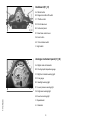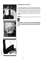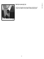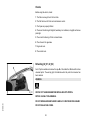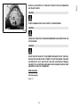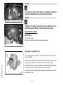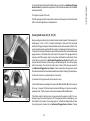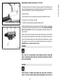
1
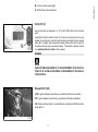
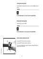
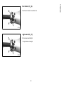
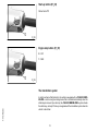
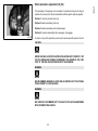
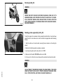
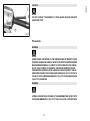
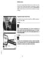
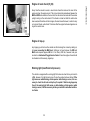
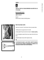
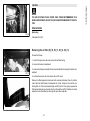
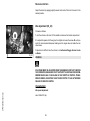
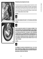
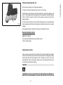
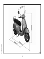
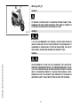
Vespa would like to thank you
for choosing one of its products. We have prepared this booklet to help you to get the very best from your scooter. Please read it carefully before riding
the vehicle for the first time. It contains information, tips and precautions for using your vehicle. It also describes features, details and devices to assure
you that you have made the right choice. We believe that if you follow our suggestions, you will soon get to know your new vehicle and use it for a long
time at full satisfaction. This booklet forms an integral part of the vehicle; should the vehicle be sold, it must be transferred to the new owner.
Vespa GTS 125
The instructions given in this booklet are intended to provide a clear, simple guide to using your scooter; details are also given of routine maintenance
procedures and regular checks that should be carried out on the vehicle at an Authorised PIAGGIO Dealer or Service Centre. The booklet also
contains instructions for simple repairs. Any operations not specifically described in this booklet require the use of special tools and/or particular technical
knowledge: to carry out these operations refer to any authorised PIAGGIO Dealer of Service Centre.
2
Personal safety
Failure to completely observe these instructions will result in serious risk of personal
injury.
Safeguarding the environment
Sections marked with this symbol indicate the correct use of the vehicle to prevent damaging the environment.
Vehicle intactness
The incomplete or non-observance of these regulations leads to the risk of serious
damage to the vehicle and sometimes even the invalidity of the guarantee.
The signs that you see on this page are very important. They are used to highlight those
parts of the booklet that should be read with particular care. As you can see, each sign
consists of a different graphic symbol, making it quick and easy to locate the various
topics.
3
4
INDEX
VEHICLE......................................................................................
Dashboard................................................................................
Analogue instrument panel.......................................................
Clock.........................................................................................
Key switch.................................................................................
Locking the steering wheel....................................................
Releasing the steering wheel................................................
Switch direction indicators........................................................
Horn button...............................................................................
Light switch...............................................................................
Start-up button..........................................................................
Engine stop button....................................................................
The immobilizer system............................................................
Keys......................................................................................
Immobilizerdevice enabled indicator led...............................
Operation...............................................................................
Programming the immobilizer system...................................
Accessing the fuel tank.............................................................
Opening the saddle...............................................................
Identification..............................................................................
Rear top box opening................................................................
USE..............................................................................................
Checks......................................................................................
Refuelling..................................................................................
Tyre pressure............................................................................
Shock absorbers adjustment....................................................
Running in.................................................................................
Starting up the engine...............................................................
Precautions...........................................................................
Difficult start up.........................................................................
Stopping the engine..................................................................
Stand.........................................................................................
Automatic transmission.............................................................
7
8
8
9
9
10
10
10
11
11
12
12
12
13
14
14
15
16
17
18
19
21
22
22
24
25
26
26
27
28
28
29
29
Safe driving...............................................................................
Rear rack..................................................................................
MAINTENANCE...........................................................................
Engine oil level..........................................................................
Engine oil level check............................................................
Engine oil top-up...................................................................
Warning light (insufficient oil pressure).................................
Engine oil change..................................................................
Hub oil level..............................................................................
Tyres.........................................................................................
Spark plug dismantlement........................................................
Removing the air filter...............................................................
Secondary air system...............................................................
Cooling fluid level......................................................................
Checking the brake oil level......................................................
Battery.......................................................................................
Use of a new battery.............................................................
Long periods of inactivity..........................................................
Fuses........................................................................................
Front light group........................................................................
Headlight adjustment.............................................................
Front direction indicators...........................................................
Rear optical unit........................................................................
Rear turn indicators...................................................................
Rear-view mirrors......................................................................
Idle adjustment..........................................................................
Front and rear disc brake..........................................................
Puncture....................................................................................
Periods of inactivity...................................................................
Cleaning the vehicle..................................................................
TECHNICAL DATA......................................................................
Kit equipment............................................................................
SPARE PARTS AND ACCESSORIES........................................
5
30
32
33
34
35
35
35
36
37
39
40
41
42
43
45
46
47
48
49
54
55
56
57
57
58
58
59
60
61
61
67
71
73
Warnings................................................................................... 74
PROGRAMMED MAINTENANCE............................................... 77
Scheduled maintenance table................................................... 78
6
Vespa GTS 125
Chap. 01
Vehicle
7
Dashboard (01_01)
A = Starter button
B = Engine block Run-Off switch
C = Throttle control
D = Front brake lever
01_01
E = Instrument panel
F = Rear brake control lever
G = Horn button
H = Turn indicator switch
I = Light switch
Analogue instrument panel (01_02)
A = Digital clock with calendar
B = Cooling liquid temperature gauge
C = Right turn indicator warning light
D = Fuel gauge
E = Headlight warning light
01_02
F = Low oil pressure warning light
G = High-beam warning light
1 Vehicle
H = Low fuel warning light
I = Speedometer
L = Odometer
8
N = Antitheft device led (immobilizer)
Clock (01_03)
Hours and minutes are displayed in a 1 to 12, AM or PM, format on the instrument
panel.
01_03
Operating the function selection switch «T» month, day and seconds can be seen
besides hours and minutes. In order to adjust the above mentioned functions, operate
button «U». The digital clock is powered by a battery (battery life is about 2 years); lift
the whole instrument panel to replace the battery. It is advisable to take your vehicle
to an Authorised Service Centre for this operation.
WARNING
DEAD BATTERIES ARE HARMFUL TO THE ENVIRONMENT. THEY MUST DISPOSED OF IN SUITABLE CONTAINERS AS PRESCRIBED BY THE REGULATIONS IN FORCE.
Key switch (01_04)
LOCK = ignition disabled, extractable key, mechanical antitheft device enabled.
OFF = ignition disabled, extractable key, mechanical antitheft device disabled.
ON = Ready to ignition position, non-extractable key, mechanical antitheft device disabled, lights on.
01_04
9
1 Vehicle
M = Left turn indicator warning light
Locking the steering wheel
Turn the handlebar to the left (as far as it will go), turn the key to «LOCK» and remove
the key.
CAUTION
DO NOT TURN THE KEY TO «LOCK» OR «KEY OFF» WHILE RIDING.
Releasing the steering wheel
Reinsert the key and turn it to «OFF».
CAUTION
DO NOT TURN THE KEY TO «LOCK» OR «KEY OFF» WHILE RIDING.
Switch direction indicators (01_05)
Lever towards "S" = Left turn indicator is switched on;
Lever towards "D" = Right turn indicator is switched on;
1 Vehicle
The lever returns automatically to position "0" and the turn indicator "B" remains on;
press the lever to turn them off.
01_05
10
Push the «C» button to sound the horn.
01_06
Light switch (01_07)
0 = Low-beam and tail light
1 = High-beam and tail light
01_07
11
1 Vehicle
Horn button (01_06)
Start-up button (01_08)
Starter button "G"
01_08
Engine stop button (01_09)
0 = OFF
1 = RUN
01_09
1 Vehicle
The immobilizer system
In order to enhance theft protection, the vehicle is equipped with a «PIAGGIO IMMOBILIZER » electronic engine locking device that is activated automatically when the
starter key is removed. Upon start-up, the «PIAGGIO IMMOBILIZER» system checks
the starter key, and only if this key is recognised will the immobilizer system allow the
vehicle to be started.
12
The vehicle is supplied with two types of keys. The red-handgrip key «A» is the
"MASTER" key. Only a single copy of this key is supplied, which is necessary to program all your other keys and for your dealer to perform some maintenance operations.
We therefore recommend that it be used only under exceptional circumstances. The
black key «B» (single copy supplied) is used for normal operations and for start-up.
Together with the keys comes a CODE CARD which is imprinted with the mechanical
code of the keys.
01_10
WARNING
LOSING THE RED KEY PREVENTS ANY REPAIRS OF THE "PIAGGIO IMMOBILIZER" SYSTEM AND THE ENGINE CONTROL UNIT.
WARNING
01_11
KEEP THE "CODE CARD" AND THE RED HANDGRIP KEY IN A SAFE PLACE
(NOT ON YOUR VEHICLE).
01_12
13
1 Vehicle
Keys (01_10, 01_11, 01_12)
Immobilizerdevice enabled indicator led (01_13)
Activation of the «PIAGGIO IMMOBILIZER» system is signalled by a flashing warning
light «N» (see «Analogue instrument panel» section).
In order to reduce battery discharge, the indicator LED turns off automatically after 48
hours of uninterrupted functioning.
Should the system fail, different LED flashing patterns will be provided by an Authorised Piaggio-Gilera Service Centre with information on the type of fault detected.
01_13
Operation
Every time the starter key is removed in the "OFF" or "LOCK" position, the safety
system activates the immobilizer system. Turning the key to "ON" disables the engine
lock, provided that the safety system recognises the code transmitted by the key. If
the code is not recognised, turn the key first to "OFF" and then to "ON"; if the lock
cannot be disabled, try with the other key supplied (red-coloured). If the engine cannot
be started, contact an Authorised Piaggio Service Centre, which is provided with
the electronic equipment required to detect and repair the system. The immobiliser is
also activated in the engine is switched off with the RUN OFF switch. This happens
even if the starter key is in position "ON".
When additional keys are required, please note that data storage (up to 3 keys max.)
must be done on all keys, both new ones and existing ones. Take the key with the red
grip and all the black keys supplied to an Authorised Piaggio Service Centre. The
codes of keys not submitted for the new storage procedure are deleted from the
memory. Any lost keys will therefore not be enabled to start the engine.
1 Vehicle
WARNING
EACH KEY HAS ITS OWN AND UNIQUE CODE, WHICH MUST BE STORED IN
THE SYSTEM CONTROL UNIT MEMORY.
14
IF OWNERSHIP OF THE VEHICLE IS TRANSFERRED, THE RED HANDGRIP KEY
(AS WELL AS THE OTHER KEYS) AND THE "CODE CARD" MUST ALSO BE
TRANSFERRED TO THE NEW OWNER.
Programming the immobilizer system
Below is described the procedure to follow for programming the PIAGGIO IMMOBILIZER system and/or for storing other key codes. The programming procedure should
be carried out with the engine stop switch set to «RUN».
Procedure start - red key
Insert the red handgrip key in the switch key (in "OFF" position) and turn it to "ON".
After 1 - 3 seconds, turn the key to «OFF » again and pull it out.
Intermediate step - black key
After pulling out the red key, insert the black key within 10 seconds and promptly turn
it to "ON". After 1-3 seconds, turn the key to "OFF" again and pull it out. In this way,
a maximum of 3 black keys can be programmed by repeating the above procedure
keeping the indicated times.
Final step - red key
After pulling out the last black key, insert the red key again and turn it to "ON" (this
operation should be performed within 10 seconds of pulling out the previous key).
Leave it in this position for 1 to 3 seconds and return it to «OFF».
15
1 Vehicle
VIOLENT SHOCKS MAY AFFECT THE ELECTRONIC COMPONENTS OF THE
KEY.
Proper programming check
Insert the red key disabling the transponder (i.e., tilt the key cap by 90°) and turn the
key to "ON". Perform the engine start-up operation. Ensure that the engine does not
start. Insert the black key and repeat the start-up operation. Check that engine starts.
WARNING
SHOULD THE ENGINE START WITH THE RED KEY (WITH TRANSPONDER OFF),
OR IN THE EVENT OF WRONG OPERATION DURING PROGRAMMING, REPEAT
THE PROCEDURE FROM THE BEGINNING.
Accessing the fuel tank (01_14, 01_15, 01_16)
With the key set to «OFF» or «ON», or with engine on, it is possible to electrically open
the saddle by pressing the button «C». If the saddle opening system does not work,
operate the emergency lever «A». Then, unscrew cap «B» and the fuel tank can be
reached.
1 Vehicle
01_14
01_15
16
1 Vehicle
01_16
Opening the saddle (01_17, 01_18)
With the key set to «OFF» or «ON», or with engine on, it is possible to electrically open
the saddle by pressing button «C». If the electric opening does not work, use the
emergency lever "A". When the key is set to «LOCK» the saddle cannot be opened.
01_17
01_18
17
Identification (01_19, 01_20, 01_21)
The identification registration numbers consist of a prefix followed by a number stamped on both the chassis «A» and the engine «B». These numbers must always be
indicated on spare parts requests. To read the chassis number, lift the saddle and
remove the helmet compartment «C». We recommend checking that the chassis registration number stamped on the vehicle corresponds with that on the vehicle documentation.
CAUTION
01_19
BE REMINDED THAT ALTERING IDENTIFICATION REGISTRATION NUMBERS
CAN LEAD TO SERIOUS PENAL SANCTIONS (IMPOUNDING OF THE VEHICLE,
ETC.).
1 Vehicle
01_20
01_21
18
Insert the key into the switch and press down until the glove compartment opens. If
the switch is set to "LOCK", turn the key to "OFF" or "ON" before pressing it down.
01_22
19
1 Vehicle
Rear top box opening (01_22)
20
1 Vehicle
Vespa GTS 125
Chap. 02
Use
21
Checks
Before using the vehicle, check:
1. That there is enough fuel in the fuel tank.
2. That the fluid level for front and rear brakes is correct.
3. That tyres are properly inflated.
4. The correct functioning of tail lights, headlamp, turn indicators, stop light and license
plate light.
5. The correct functioning of front and rear brakes.
6. The oil level in the gearcase.
7. Engine oil level.
8. The coolant level.
Refuelling (02_01, 02_02)
Fuel: lift up the saddle and unscrew the cap «B». Prescribed fuel: Minimum 95 octane
unleaded petrol. The warning light «C»indicates when the petrol tank reserve has
been reached.
WARNING
02_01
SWITCH OFF THE ENGINE BEFORE REFUELLING WITH PETROL.
PETROL IS HIGHLY INFLAMMABLE.
2 Use
DO NOT SMOKE AND KEEP NAKED FLAMES AT A DISTANCE:FIRE HAZARD.
DO NOT INHALE FUEL FUMES.
22
CAUTION
PETROL DAMAGES THE PLASTIC PARTS OF THE BODYWORK.
CAUTION
02_02
USING OILS OTHER THAN THOSE RECOMMENDED CAN SHORTEN THE LIFE
OF THE ENGINE.
CAUTION
DO NOT USE THE VEHICLE TO THE COMPLETE EXHAUSTION OF THE FUEL;
SHOULD THIS OCCUR, DO NOT ATTEMPT TO START THE ENGINE. TURN THE
KEY SWITCH TO «OFF» AND TOP-UP THE TANK AS SOON AS POSSIBLE.
FAILURE TO FOLLOW THESE GUIDELINES COULD DAMAGE THE FUEL PUMP
AND/OR THE CATALYTIC CONVERTER.
Characteristic
Fuel tank capacity
About 10 l
23
2 Use
DO NOT ALLOW PETROL TO COME INTO CONTACT WITH HOT ENGINE OR
ANY PLASTIC PARTS.
Tyre pressure (02_03)
Check the tyre pressure and wear periodically (roughly every 500 km). The tyres are
equipped with wear indicators; the tyres should be replaced as soon as these indicators become visible on the tyre tread. Also check that tyres do not show cuts on the
sides or irregular tread wear; if this occurs, go to an authorised workshop or at least
a workshop equipped to perform the replacement.
CAUTION
02_03
TYRE PRESSURE SHOULD BE CHECKED WHEN TYRES ARE COLD.INCORRECT TYRE PRESSURE CAUSES ABNORMAL TYRE WEAR AND MAKES RIDING DANGEROUS.
TYRES MUST BE REPLACED WHEN THE TREAD REACHES THE WEAR LIMITS
SET FORTH BY LAW.
Characteristic
Front tyre pressure
1.8 bar
Rear tyre pressure
2 bar
Rear tyre pressure - driver and passenger
2 Use
2.2 bar
24
The preloading of the springs can be adjusted to 4 positions acting on the ring nut
located in the lower part of the shock absorbers with the specific spanner supplied.
Position 1: minimum preload: driver only
Position 2 medium preloading: rider only
Position 3 medium preloading: rider and passenger
Position 4: maximum preloading: rider, passenger, and luggage.
02_04
In order to carry out this operation you will need to use the specific spanner in the kit.
CAUTION
RIDING THE VEHICLE WITH THE SPRING PRELOADING NOT CORRECTLY SET
FOR THE RIDER AND POSSIBLE PASSENGER, COULD REDUCE THE COMFORT OF THE RIDE AND THE PRECISION OF THE STEERING.
WARNING
WE RECOMMEND WEARING GLOVES WHILE CARRYING OUT THIS OPERATION IN ORDER TO AVOID INJURIES.
WARNING
WE STRONGLY RECOMMEND NOT TO ADJUST BOTH SHOCK ABSORBERS
WITH DIFFERENT PRELOADING
25
2 Use
Shock absorbers adjustment (02_04)
Running in (02_05)
WARNING
02_05
DURING THE FIRST 1000 KM DO NOT RIDE THE VEHICLE OVER 80% OF ITS
MAXIMUM SPEED. AVOID TWISTING THE THROTTLE GRIP FULLY OR KEEPING A CONSTANT SPEED ALONG LONG SECTIONS OF ROAD. AFTER THE
FIRST 1000 KM, GRADUALLY INCREASE SPEED UNTIL REACHING THE MAXIMUM PERFORMANCE.
Starting up the engine (02_06, 02_07)
To start the engine it is necessary, before pressing the starter button, to pull and keep
pulled the front or rear brake lever, which activates the appropriate switch allowing
start-up.
1. Rest the vehicle on its centre-stand, ensuring the rear wheel is not touching the
ground.
2. Maintain the throttle grip «E» completely untwisted.
3. insert key into ignition switch «A» and turn it to "ON".
02_06
4. Make sure that the «B» "OFF-ON" switch is set to ON.
5. Pull lever «C» of the front or rear brake and then activate the starter button «D».
2 Use
WARNING
THE AUTOMATIC TRANSMISSION MAKES THE REAR WHEEL TURN EVEN
WHEN THE THROTTLE IS SLIGHTLY TWISTED. RELEASE THE BRAKE CAREFULLY AFTER STARTING, AND THEN ACCELERATE GRADUALLY.
26
2 Use
CAUTION
DO NOT START-UP THE ENGINE IN CLOSED AREAS BECAUSE EXHAUST
GASES ARE TOXIC.
02_07
Precautions
WARNING
NEVER STRESS THE ENGINE AT LOW TEMPERATURES IN ORDER TO AVOID
POSSIBLE DAMAGE. BE CAREFUL NEVER TO EXCEED THE MAXIMUM SPEED
WHILE RUNNING DOWNHILL, IN ORDER TO AVOID DAMAGING THE ENGINE.
IN ANY CASE, IN ORDER TO PRESERVE THE ENGINE FROM PROLONGED
OVERREVVING, THE REVOLUTION LIMITER WILL BE ACTIVATED IF THE ENGINE SPEED EXCEEDS THE ESTABLISHED THRESHOLD. DO NOT ACTIVATE
THE REVOLUTION LIMITER RECURRENTLY SO AS TO AVOID DAMAGING THE
CATALYTIC CONVERTER.
WARNING
AFTER A LONG DISTANCE COVERED AT THE MAXIMUM SPEED, DO NOT STOP
THE ENGINE IMMEDIATELY, BUT LET IT RUN AT IDLE FOR A FEW SECONDS.
27
Difficult start up
In the rare case of engine flooding, to facilitate start-up, it is possible to try to put the
vehicle into action with the gas hand grip partially or completely open. It is however
necessary, once the engine is started, to take your vehicle to an Authorised Service
Centre to determine the cause of this problem and to re-establish the vehicle proper
functioning.
Stopping the engine (02_08, 02_09)
Fully untwist the throttle grip and then turn the switch «A» to "OFF" (extractable key),
or turn switch «B» to "OFF".
CAUTION
02_08
DUE TO THE HIGH TEMPERATURES THE CATALYTIC CONVERTER CAN
REACH, ALWAYS TAKE CARE, WHEN PARKING THE VEHICLE, THAT THE EXHAUST DOES NOT COME INTO CONTACT WITH FLAMMABLE MATERIALS, TO
AVOID SERIOUS BURNS.
CAUTION
DO NOT SHUT OFF THE ENGINE WHILE THE VEHICLE IS MOVING. UNBURNED
FUEL COULD ENTER THE CATALYTIC CONVERTER AND BURN, CAUSING THE
CONVERTER TO OVERHEAT AND POSSIBLY DESTROYING IT.
2 Use
02_09
28
2 Use
Stand (02_10)
CENTRE STAND
Push with your foot on the centre stand's fork «F» while lifting the vehicle backward,
holding onto the handlebar.
SIDE STAND
With your foot push the projection of the stand «L » in order to open it and at the same
time lean the vehicle on you.
02_10
Automatic transmission (02_11, 02_12)
To ensure simple, pleasurable riding, the vehicle is equipped with automatic transmission with regulator and centrifugal clutch. The system is designed to provide the
best performance (acceleration and consumption) while riding on both flat roads and
uphill.
If you have to stop on an uphill slope (traffic lights, traffic jam, etc.) use only the brake
to keep the vehicle still, leaving the engine running at idle speed. Using the
engine to keep the vehicle still can cause the clutch to overheat, due to the
friction of the clutch mechanism itself against the clutch bell.
02_11
It is therefore recommended to avoid conditions of prolonged clutch slippage (other
than those previously indicated) like driving uphill fully laden on steep slopes or starting
off with driver and passenger at slopes greater than 25%.
Observe the following precautions if the clutch overheats:
29
1.Do not continue riding in such conditions.
2. Let the clutch cool down with the engine at idle speed for a few minutes.
02_12
Safe driving (02_13, 02_14)
Some simple tips are provided below that will enable you to use your scooter on a
daily basis in greater safety and peace of mind. Your skill and your mechanical knowledge are the basis of a safe ride. We recommend trying out the vehicle in traffic - free
zones, in order to acquire a good knowledge of the vehicle it self.
1. Before riding off, remember to put on your helmet and fasten it correctly.
2.Reduce speed on rough roads and drive with care.
02_13
3. After driving on a long stretch of wet road without using the brakes, the braking
effect is initially lower. In these conditions, it is a good idea to apply the brakes from
time to time.
4. Do not brake hard on wet, unsurfaced or slippery road surfaces.
5. Avoid riding off by mounting the scooter when resting on the support. In any case,
the rear wheel should not be turning when in comes into contact with the ground, in
order to avoid abrupt departures.
2 Use
6. If driving over roads affected by sand, mud, snow mixed with salt, etc. We advise
you to frequently clean the brake disc with a mild detergent to prevent the accumulation of abrasive elements inside the eyelets leading to premature wear on the brake
pads.
02_14
30
2 Use
CAUTION
ALWAYS RIDE WITHIN YOUR LIMITS RIDING UNDER THE INFLUENCE OF ALCOHOL OR OTHER DRUGS AND CERTAIN MEDICINES IS EXTREMELY DANGEROUS.
CAUTION
ANY CHANGES TO THE VEHICLE PERFORMANCE AS WELL AS ALTERATIONS
TO ORIGINAL STRUCTURAL PARTS IS STRICTLY FORBIDDEN BY LAW, AND
RENDERS THE VEHICLE NO LONGER CONFORMING TO THE APPROVED TYPE
AND DANGEROUS FOR RIDING.
CAUTION
DO NOT ADJUST THE MIRRORS WHILE RIDING. THIS COULD CAUSE YOU TO
LOOSE CONTROL OVER THE VEHICLE.
WARNING
IN ORDER TO PREVENT ANY ACCIDENTS RIDE VERY CAREFULLY AFTER
ADDING ACCESSORIES AND WHILE CARRYING LUGGAGE. THE ADDITION OF
ACCESSORIES AND LUGGAGE CAN REDUCE YOUR SCOOTER STABILITY
AND PERFORMANCE, AS WELL AS THE LEVEL OF SAFETY DURING USE.
NEVER DRIVE THE SCOOTER EQUIPPED WITH ACCESSORIES AT A SPEED
HIGHER THAN 100 km/h (see section "SPARE PARTS AND ACCESSORIES")
.
31
Rear rack (02_15)
When riding without packages on the luggage racks, set the corresponding retainer
latch "A" as shown in the photograph.
WARNING
Maximum admissible load: 6 kg
2 Use
02_15
32
Vespa GTS 125
Chap. 03
Maintenance
33
03_01
Engine oil level (03_01)
3 Maintenance
In 4T engines, engine oil is used to lubricate the distribution elements, main bearings
and thermal group. An insufficient quantity of oil can seriously damage the engine. In all four-stroke engines, a loss of efficiency in oil performance and certain
consumption should be considered normal. Consumption can particularly reflect the
conditions of use (i.e. when driving at 'full acceleration' all the time, oil consumption
increases). The replacement intervals provided for by the maintenance programme
are defined depending on the total content of oil in the engine and the average consumption measured following standardised methods. In order to prevent any problems, we recommend checking oil level more frequently than indicated in the
Scheduled Maintenance table or before setting off on long journeys. The vehicle
is, however, equipped with an oil pressure warning light on the instrument panel.
34
Every time the scooter is used, a visual check should be made on the level of the
engine oil when the engine is cold. The oil level should be somewhere between the
MAX and MIN index marks on the level bar; the check must be made with the scooter
upright, resting on the centre stand. If the check is carried out after the vehicle has
been used, and therefore with a hot engine, the level line will be lower; in order to carry
out a correct check, wait at least 10 minutes after the engine has been stopped so as
to get the correct level.
03_02
Engine oil top-up
Any topping up with oil must be carried out after checking the oil level by adding oil,
but never exceeding the MAX level. Getting an oil level between the MIN and
MAX marks requires approx. 400 cm³ of oil. Every 3000 km, however, take your
scooter to an Authorised Piaggio Service Centre to have the engine oil level should
be checked and if necessary, topped up.
Warning light (insufficient oil pressure)
The vehicle is equipped with a warning light that comes on when the key is turned to
«ON». However, this light should come off once the engine has been started. If the
light comes on while braking, at idle speed or while turning a corner, it is necessary to check the oil level and top it up if required. If after having topped-up
the oil, the warning light still comes on while braking, at idle speed or while
turning a corner, it will be necessary to take your vehicle to an Authorised Service Centre.
35
3 Maintenance
Engine oil level check (03_02)
Engine oil change (03_03)
The oil and the cartridge filter «C» must be changed after 1000 km and every 6000
km at an Authorised Piaggio Service Centre. The engine should be emptied by
draining the oil from the drainage plug «B» of the gauze filter on the flywheel side. In
order to facilitate the oil drainage, loosen the cap/dipstick. Since a certain quantity of
oil still remains in the circuit, filling must be done with approx 600 ÷ 650 cm³ of oil
through the cap «A». Then start up the scooter, leave it running for a few minutes and
switch it off: after five minutes, check the level and if necessary top-up without exceeding the MAX. level. The cartridge filter must be replaced at every oil change.
For top-ups and changes, use new oil of the recommended type.
03_03
WARNING
RUNNING THE ENGINE WITH INSUFFICIENT LUBRICATION OR WITH INADEQUATE LUBRICANTS ACCELERATES THE WEAR AND TEAR OF THE MOVING
PARTS AND CAN CAUSE IRRETRIEVABLE DAMAGE.
WARNING
EXCESSIVE OIL LEVEL AT TOP-UPS CAN LEAD TO SCALE FORMATION AND
VEHICLE MALFUNCTION.
3 Maintenance
CAUTION
USED OILS CONTAIN SUBSTANCES HARMFUL TO THE ENVIRONMENT. FOR
OIL CHANGE, CONTACT AN AUTHORISED SERVICE CENTRE WHICH IS EQUIPPED TO DISPOSE OF USED OILS IN AN ENVIRONMENTALLY FRIENDLY AND
LEGAL WAY.
36
USING OILS OTHER THAN THOSE RECOMMENDED CAN SHORTEN THE LIFE
OF THE ENGINE.
Recommended products
AGIP CITY HI TEC 4T
Engine oil
SAE 5W-40, API SL, ACEA A3, JASO MA Synthetic oil
Hub oil level (03_04, 03_05)
Check the oil in the rear hub. To check the rear hub oil level, proceed as follows:
1) Park the scooter on level ground and rest it on its stand.
2) Unscrew dipstick "A", wipe it clean with a cloth, reinsert it and tighten completely.
3) Pull out the dipstick and check that the oil level is above the first notch from the
bottom.
4) Reinsert the dipstick and ensure that it is tightened correctly.
03_04
N.B.
THE NOTCHES ON THE HUB OIL LEVEL DIPSTICK, EXCEPT THE ONE INDICATING THE MAX LEVEL, REFER TO OTHER MODELS BY THE MANUFACTURER AND HAVE NO SPECIFIC FUNCTION FOR THIS MODEL.
03_05
37
3 Maintenance
CAUTION
CAUTION
RIDING THE VEHICLE WITH INSUFFICIENT HUB LUBRICATION OR WITH CONTAMINATED OR IMPROPER LUBRICANTS ACCELERATES THE WEAR AND
TEAR OF THE MOVING PARTS AND CAN CAUSE SERIOUS DAMAGE.
CAUTION
USED OIL CAN HARM THE ENVIRONMENT. COLLECTION AND DISPOSAL
SHOULD BE CARRIED OUT IN COMPLIANCE WITH REGULATIONS IN FORCE.
CAUTION
AN EXCESSIVE QUANTITY OF OIL CAN LEAD TO SPILL OVER, WHICH MAY
CAUSE THE ENGINE AND THE WHEEL TO GET DIRTY.
CAUTION
WHEN REPLACING THE HUB OIL DO NOT LET THE OIL COME INTO CONTACT
WITH THE REAR BRAKE DISC.
3 Maintenance
CAUTION
FOR OIL REPLACEMENT, CONTACT ANY AUTHORISED SERVICE CENTRE AS
THEY ARE EQUIPPED TO DISPOSE OF USED OILS IN AN ENVIRONMENTALLY
FRIENDLY AND LEGAL WAY.
38
AGIP ROTRA 80W-90
Rear hub oil
SAE 80W/90 Oil that exceeds the requirements of API GL3 specifications
Characteristic
rear hub oil capacity
Capacity: approx. 150 cm³
Tyres (03_06)
Check tyre pressure periodically (about every 500 km). Tyres feature wear indicators;
replace tyres as soon as these indicators become visible on the tyre tread. Also check
that the tyres do not show signs of splitting at the side or irregular tread wear; if this
occurs, go to an authorised workshop or at least to a workshop equipped to perform
the replacement.
CAUTION
03_06
TYRE PRESSURE SHOULD BE CHECKED WHEN TYRES ARE COLD.INCORRECT TYRE PRESSURE CAUSES ABNORMAL TYRE WEAR AND MAKES RIDING DANGEROUS.
TYRES MUST BE REPLACED WHEN THE TREAD REACHES THE WEAR LIMITS
SET FORTH BY LAW.
Characteristic
Front tyre pressure
1.8 bar
39
3 Maintenance
Recommended products
Rear tyre pressure
2 bar
Rear tyre pressure - driver and passenger
2.2 bar
Spark plug dismantlement (03_07, 03_08, 03_09)
Proceed as follows:
1. lift the saddle «A»
2. lift the helmet compartment «B» and reach into the spark plug with your hand;
3. remove the spark plug HV wire cap «C»;
4. unscrew the spark plug using the spark plug spanners «D» supplied;
03_07
5. When refitting, place the spark plug in the hole at the due inclination and screw it
by hand until it is finger tight;
6. use the box-spanner«D» supplied only for locking;
7. push cap «C» fully on the spark plug.
3 Maintenance
CAUTION
03_08
THE SPARK PLUG MUST BE REMOVED WHEN THE ENGINE IS COLD. THE
SPARK PLUG SHOULD BE CHECKED EVERY 6,000 KM AND REPLACED EVERY
12,000 KM. THE USE OF NON-CONFORMING IGNITION CONTROL UNITS AND
SPARK PLUGS OTHER THAN THOSE PRESCRIBED CAN SERIOUSLY DAMAGE
THE ENGINE
.
40
THE USE OF SPARK PLUGS OTHER THAN THOSE RECOMMENDED OR A
SHIELDLESS SPARK PLUG CAP COULD CAUSE DISTURBANCES TO THE SYSTEM.
Characteristic
03_09
Spark plug
Champion RG 4 HC
Removing the air filter (03_10, 03_11, 03_12, 03_13)
Proceed as follows:
1. undo the fixing screws «A» and remove the left side fairing;
2. remove the helmet compartment;
03_10
3. unscrew the fixing screws «B» that can be reached after removing the helmet compartment;
4. unscrew the screws «C» and remove the air filter cover.
Remove the filtering element and clean it with water and shampoo; then dry it with a
clean cloth and short blasts of compressed air. Finally, immerse it in a mixture containing 50% oil of the recommended type and 50% petrol. Then gently squeeze the
filter element between your hands, allow it to drip and then refit it. Possible oil or water
deposits can be eliminated by removing the two rubber caps «D».
03_11
41
3 Maintenance
CAUTION
CAUTION
IF THE VEHICLE IS USED ON DUSTY ROADS, IT IS NECESSARY TO SERVICE
THE AIR FILTER MORE OFTEN TO AVOID DAMAGING THE ENGINE.
CAUTION
03_12
IN ORDER NOT TO DAMAGE THE VEHICLE PLASTIC COVERS CONTACT AN
AUTHORISED SERVICE CENTRE TO HAVE THE AIR FILTER CLEANED.
Recommended products
AGIP FILTER OIL
Oil for air filter sponge
Mineral oil with specific additives for increased adhesiveness
03_13
Secondary air system (03_14)
In order to reduce polluting emissions, the vehicle is furnished with a catalytic converter in the muffler.
3 Maintenance
To facilitate the catalytic process, a further quantity of previously filtered air is brought
in through the exhaust duct on the head by the secondary air system (SAS).
This system allows more oxygen to be added to the unburned gases before reaching
the catalytic converter, thus improving the catalytic converter reaction.
03_14
The system has a control valve that disables operation during deceleration in order to
avoid abnormal noises.
42
This system requires a filter «A».
The filter sponge should be cleaned with water and mild soap, then it should be dried
with a cloth and slight blows of compressed air.
Cooling fluid level (03_15, 03_16)
03_15
Engine cooling is carried out by a forced-circulation coolant system. The cooling circuit
holds approx. 2.100 ÷ 2.150 l of coolant consisting of a mixture of 50% de-ionised
water and 50% glycol ethylene-based antifreeze solution with corrosion inhibitors. The
recommended coolant, supplied with the scooter, is already mixed and ready for use.
For proper functioning of the engine, ensure that the pointer of the coolant temperature
gauge remains in the middle area of the scale. If the pointer of the gauge enters the
red zone, shut off the engine, allow it to cool down and check the coolant level; if level
is OK, take your scooter to an Authorised Piaggio Service Centre. Should the coolant level exceed the above values during a non-demanding ride, shut off the engine
and let it cool down. Then check the coolant level. if level is OK, take your scooter to
an Authorised Piaggio Service Centre. Check coolant when the engine is cold at
the intervals indicated in the scheduled maintenance table, following the steps below.
a) Place the scooter in a vertical position on the stand.
b) Unscrew the fixing screw «A» and remove the cover.
c) Check the fluid level according to the two marks- MIN and MAX «B» on the reservoir
d) Top-up, if required, if the fluid level is below the MIN level on the scale inside the
expansion tank. The fluid level must always be between MIN and MAX level
03_16
If the fluid is near the minimum level, top-up only when the engine is cold. If it is necessary to top up the coolant frequently, or if the expansion tank is completely dry, you
should look for the cause in the cooling system. It is therefore indispensable to have
the cooling system checked at an Authorised Piaggio Service Centre. Change
43
3 Maintenance
To ensure the best functioning of the SAS, take your vehicle to an Authorised Piaggio
Service Centre for maintenance operations, at the intervals indicated in the scheduled
maintenance table.
coolant at the intervals indicated in the scheduled maintenance table. For this operation, please contact an Authorised Piaggio Service Centre.
WARNING
TO AVOID THE RISK OF SCALDING, DO NOT UNSCREW THE EXPANSION
TANK COVER WHILE THE ENGINE IS STILL HOT.
WARNING
TO PREVENT AVOID HARMFUL FLUID LEAKAGE WHILE RIDING, ENSURE
THAT THE LEVEL NEVER EXCEEDS THE MAXIMUM VALUE.
TO ENSURE CORRECT ENGINE OPERATION, KEEP THE RADIATOR GRILLE
CLEAN.
Recommended products
SPECIAL AGIP PERMANENT fluid
3 Maintenance
coolant
Monoethylene glycol-based antifreeze fluid, CUNA NC 956-16
44
The brake fluid reservoirs are located on the pumps under the front handlebar cover
(front on the right-hand side, rear on the left-hand side). The procedures to checking
the brake fluid level for the front and rear brakes are identical.
Proceed as follows:
1. rest the scooter on its centre stand and make sure the handlebar is centred;
2. loosen screw "A" and remove cover "B";
03_17
3. check the fluid level through the respective sight glass "C".
A certain lowering of the level is caused by wear on the pads. Should the level appear
to be below the minimum mark, please contact your nearest Authorised PIAGGIO
Dealer or Service Centre in order to have braking system thoroughly inspected. Proceed as follows:
Remove tank cover «D» and loosen the two screws «E» and top-up the brake fluid
level using only the prescribed brake fluid and without exceeding the maximum level.
Under normal climatic conditions, the brake fluid should be replaced every 2 years.
This operation must be carried out by trained technicians; take your scooter to a
PIAGGIO Dealer or authorised Service Centre.
03_18
WARNING
ONLY USE DOT 4 CLASS BRAKE FLUIDS. BRAKING CIRCUIT FLUIDS ARE
HIGHLY CORROSIVE. MAKE SURE THAT IT DOES NOT COME INTO CONTACT
WITH THE PAINTWORK
.
CAUTION
AVOID CONTACT OF BRAKE FLUID WITH EYES, SKIN, AND CLOTHING. IN
CASE OF CONTACT, RINSE WITH WATER. THE BRAKING CIRCUIT FLUID IS
45
3 Maintenance
Checking the brake oil level (03_17, 03_18)
HYGROSCOPIC, THAT IS, IT ABSORBS HUMIDITY FROM THE SURROUNDING
AIR. IF THE HUMIDITY IN THE BRAKING FLUID EXCEEDS A CERTAIN VALUE,
IT WILL LEAD TO INEFFICIENT BRAKING. NEVER USE BRAKING FLUID KEPT
IN CONTAINERS THAT HAVE ALREADY BEEN OPENED, OR PARTIALLY USED.
Recommended products
AGIP BRAKE 4
Brake fluid
FMVSS DOT 4 Synthetic fluid
Battery (03_19, 03_20, 03_21)
To reach the battery «D », proceed as follows:
1. rest the scooter on its centre stand;
2. unscrew the 4 screws «A», remove the footrest «B».
3. remove the two battery fixing screws «C».
The battery is the electrical device that requires the most frequent inspections and
diligent maintenance. The main points of maintenance to be observed are as follows:
3 Maintenance
03_19
CAUTION
IN ORDER TO AVOID DAMAGING THE ELECTRICAL SYSTEM, NEVER DISCONNECT THE WIRING WHILE THE ENGINE IS RUNNING. DO NOT TIP THE SCOOTER TOO MUCH IN ORDER TO AVOID DANGEROUS LEAKS OF BATTERY
ELECTROLYTE
.
03_20
46
ELECTROLYTE CONTAINS SULPHURIC ACID: AVOID CONTACT WITH EYES,
SKIN AND CLOTHES. IN CASE OF ACCIDENTAL CONTACT, RINSE WITH ABUNDANT WATER AND CONSULT A DOCTOR.
WARNING
03_21
USED BATTERIES ARE HARMFUL FOR THE ENVIRONMENT. COLLECTION
AND DISPOSAL SHOULD BE CARRIED OUT IN COMPLIANCE WITH REGULATIONS IN FORCE.
Use of a new battery
Ensure that the terminals are connected correctly and check voltage.
CAUTION
DO NOT REVERSE THE POLARITY: RISK OF SHORT CIRCUIT AND DAMAGE
TO THE ELECTRICAL SYSTEM.
WARNING
USED BATTERIES ARE HARMFUL FOR THE ENVIRONMENT. COLLECTION
AND DISPOSAL SHOULD BE CARRIED OUT IN COMPLIANCE WITH REGULATIONS IN FORCE.
47
3 Maintenance
CAUTION
Long periods of inactivity
Battery performance will decrease if the vehicle is not used for a long time. This is the
result of the natural phenomenon of battery discharging plus residual absorption by
vehicle components with constant power consumption. Poor battery performance may
also be due to environmental conditions and the cleanliness of the poles. In order to
avoid difficult starts and/or irreversible damage to the battery, follow any of these
steps:
- At least once a month start the engine and run it slightly above idle speed for 10-15
minutes. This keeps all the engine components, as well as the battery, in good working
order.
- Take your vehicle to a garage (as indicated in the «Vehicle not used for extended
periods» section) to have the battery removed. Have the battery cleaned, charged
fully and stored in a dry, ventilated place. Recharge at least once every two
months.
N.B.
THE BATTERY MUST BE CHARGED WITH A CURRENT EQUAL TO 1/10 OF THE
RATED CAPACITY OF THE BATTERY AND FOR NOT LONGER THAN 10 HOURS.
CONTACT AN AUTHORISED SERVICE CENTRE TO CARRY OUT THIS OPERATION SAFELY. WHEN REFITTING THE BATTERY MAKE SURE THE LEADS ARE
CORRECTLY CONNECTED TO THE TERMINALS.
3 Maintenance
WARNING
DO NOT DISCONNECT THE BATTERY CABLES WITH THE ENGINE RUNNING,
THIS CAN CAUSE PERMANENT DAMAGE TO THE VEHICLE ELECTRONIC CONTROL UNIT.
48
USED BATTERIES ARE HARMFUL FOR THE ENVIRONMENT. COLLECTION
AND DISPOSAL SHOULD BE CARRIED OUT IN COMPLIANCE WITH REGULATIONS IN FORCE.
Fuses (03_22, 03_23)
The electrical system is equipped with:
1. six protection fuses «A» located in the glove compartment to the left
2. one 15A fuse «B» located under the helmet compartment under the saddle hinge
latch.
The chart shows the position and characteristics of the fuses in the vehicle.
CAUTION
BEFORE REPLACING A BLOWN FUSE, FIND AND SOLVE THE FAILURE THAT
CAUSED IT TO BLOW. NEVER TRY TO REPLACE A FUSE WITH ANY OTHER
MATERIAL (A PIECE OF ELECTRIC WIRE, FOR INSTANCE).
CAUTION
MODIFICATIONS OR REPAIRS TO THE ELECTRICAL SYSTEM, PERFORMED
INCORRECTLY OR WITHOUT STRICT OBSERVANCE OF THE TECHNICAL
SPECIFICATIONS OF THE SYSTEM, CAN CAUSE OPERATING ERRORS AND
RISK OF FIRE.
49
3 Maintenance
WARNING
FUSES
Fuse 1
Current rating: 10 A
Protected circuits: High-/lowbeam headlight bulb, high-beam
warning light.
Fuse 2
Current rating: 7.5 A
Protected
circuits:
Saddleopening actuator, immobilizer
LED, anti-theft device preinstallation, key switch
Fuse 3
Current rating: 7.5 A
Protected circuits: Horn, antitheft
device pre-installation, oil pressure
sensor, oil pressure warning light,
water
temperature
gauge,
thermistor, fuel gauge, low fuel
warning light, fuel level transmitter.
Fuse 4
Current rating: 5 A
3 Maintenance
Protected circuits: Instrument
panel lighting bulbs and warning
lights, tail lights, license plate light.
Fuse 5
Current rating: 5 A
Protected circuits: Stop light,
starter motor.
Fuse 6
Current rating: 3 A
50
Fuse 7
3 Maintenance
Protected circuits: Electric pump
control device, fuel electric pump
Current rating: 15A
Protected circuits: General
03_22
03_23
51
BULBS
Low-/high-beam light bulb
Type: HALOGEN (H4)
Power: 12V - 55/60W
Quantity: 1
Front tail light bulb
Type: ALL GLASS
Power: 12V - 5W
Quantity: 2
Licence plate light bulb
Type: ALL GLASS
Power: 12V - 5W
Quantity: 1
Front turn indicator bulb
Type: ALL GLASS
Power: 12V - 10W
Quantity: 2
Rear turn indicator bulb
Type: SPHERICAL (AMBER)
Power: 12V - 10W
Quantity: 2
3 Maintenance
Rear tail light bulb
Type: ALL GLASS
Power: 12V - 5W
Quantity: 1
Stop light bulb
Type: ALL GLASS
52
3 Maintenance
Power: 12V - 16W
Quantity: 1
Tail light warning light bulb
Type: ALL GLASS
Power: 12V - 2W
Quantity: 1
High-beam warning light bulb
Type: ALL GLASS
Power: 12V - 1.2W
Quantity: 1
Low fuel warning light bulb
Type: ALL GLASS
Power: 12V - 1.2W
Quantity: 1
Oil pressure warning light bulb
Type: ALL GLASS
Power: 12V - 1.2W
Quantity: 1
(Right and left) turn indicator
warning light bulbs
Type: ALL GLASS
Power: 12V - 2W
Quantity: 2
Panel lighting bulb
Type: ALL GLASS
Power: 12V - 2W
Quantity: 3
53
Front light group (03_24, 03_25, 03_26, 03_27, 03_28)
To remove the front headlight assembly, proceed as follows:
1: remove rear-view mirrors.
2: Remove the screws «A» of the front shield grille.
3: Remove the fixing screws «B» of the front handlebar cover.
4: Remove the fixing screws «C» of the rear handlebar cover
03_24
5: Remove the front handlebar cover.
So there is access to the bulbs. Open the clip and take out the high-/low-beam light
bulb «D».To change the tail light take out the rubber light socket from the seat. To
reassemble, repeat the operation in the reverse order.
WARNING
THE TWIN-FILAMENT (HIGH-BEAM AND LOW-BEAM) BULB IS HALOGEN: DO
NOT TOUCH THE BULB WITH YOUR FINGERS TO AVOID COMPROMISING ITS
FUNCTIONING
3 Maintenance
03_25
03_26
54
3 Maintenance
03_27
03_28
Headlight adjustment (03_29, 03_30)
Proceed as follows:
1. Place the vehicle, in running order and with the tyres inflated to the prescribed
pressure, on a flat surface 10-m away from a white screen situated in a shaded area,
making sure that the longitudinal axis of the scooter is perpendicular to the screen;
2. Turn on the headlight and check that the borderline of the projected light beam on
the screen is not higher than 9/10 or lower than 7/10 of the distance from the ground
to the centre of vehicle headlamp;
03_29
3. If otherwise, adjust the right headlight with screw «A».
55
N.B.
THE ABOVE PROCEDURE COMPLIES WITH THE EUROPEAN STANDARDS REGARDING MAXIMUM AND MINIMUM HEIGHT OF LIGHT BEAMS. REFER TO THE
STATUTORY REGULATIONS IN FORCE IN EVERY COUNTRY WHERE THE VEHICLE IS USED.
03_30
Front direction indicators (03_31)
To replace the burnt bulb, remove the screws «F»
3 Maintenance
03_31
56
Remove screw «A» to remove the rear headlight assembly.
Access to taillight bulbs, stop light bulb and license plate bulb.
To reassemble, repeat the operation in the reverse order.
N.B.
03_32
IF MISTING IS NOTICED ON THE INSIDE OF THE HEADLAMP GLASS, THIS
DOES NOT INDICATE A FAULT AND IS ATTRIBUTABLE TO HUMIDITY AND/OR
TO LOW TEMPERATURES.
THE PHENOMENON SHOULD QUICKLY DISAPPEAR WHEN THE LIGHT IS
SWITCHED ON.
THE PRESENCE OF DROPS OF WATER, ON THE OTHER HAND, COULD INDICATE THAT WATER IS INFILTRATING. CONTACT THE AFTER-SALES SERVICE
NETWORK.
Rear turn indicators (03_33)
To gain access to the turn indicator bulbs, remove the fastening screws «E».
The bulbs have a bayonet coupling, to remove them press gently and twist anticlockwise about 30°. To refit follow the same steps but in reverse order.
03_33
57
3 Maintenance
Rear optical unit (03_32)
Rear-view mirrors
Adjust the mirrors by applying slight pressure to the side of the mirror to move it to the
desired position.
Idle adjustment (03_34)
Proceed as follows:
1. rest the vehicle on its stand, lift the saddle and remove the helmet compartment.
2. to adjust idle speed, start the engine, then tighten or loosen the screw «B» until you
reach the recommended idle speed making sure the engine does not make the rear
wheel move.
If adjustment is difficult, take the vehicle to an Authorised Piaggio Service Centre
or Dealer.
03_34
WARNING
IDLE SPEED MUST BE ADJUSTED WHEN THE ENGINE IS VERY HOT. BEFORE
THIS OPERATION, MAKE SURE THAT THE THROTTLE GRIP HAS THE RECOMMENDED BACKLASH. IF BACKLASH IN THE THROTTLE CONTROL TRANSMISSION NEEDS ADJUSTING TAKE YOUR SCOOTER TO AN AUTHORISED
DEALER OR SERVICE CENTRE.
Characteristic
3 Maintenance
Idle speed adjustment
about 1650±100 rpm
58
The brake disc and pad wear is automatically compensated, therefore it has no effect
on the functioning of the front and rear brakes. For this reason it is not necessary to
adjust the brakes. An excessively elastic brake lever stroke may indicate the presence
of air in the braking circuit or a failure in the braking system. In this case, mainly due
to the importance of brakes to guarantee safe riding conditions, the vehicle should be
taken to an Authorised Service Centre or Dealer.
CAUTION
03_35
BRAKING SHOULD BEGIN AFTER ABOUT 1/3 OF THE BRAKE LEVER STROKE.
CAUTION
HAVE THE BRAKE PADS CHECKED BY THE DEALER ACCORDING TO THE
CHECKS SPECIFIED IN THE SCHEDULED MAINTENANCE TABLE. HOWEVER,
IN THE EVENT OF NOISES COMING FROM THE FRONT AND/OR REAR BRAKING SYSTEM DURING OPERATION, IT IS ADVISABLE TO HAVE THE BRAKING
SYSTEM CHECKED BY AN AUTHORISED SERVICE CENTRE OR DEALER. AFTER REPLACING THE BRAKE PADS, DO NOT USE THE SCOOTER UNTIL YOU
HAVE OPERATED THE BRAKE LEVER SEVERAL TIMES IN ORDER TO ALLOW
THE PLUNGERS TO SETTLE AND THE LEVER STROKE TO BE SET TO THE
CORRECT POSITION.
03_36
CAUTION
THE PRESENCE OF SAND, MUD, SNOW MIXED WITH SALT, ETC. ON THE
ROAD, CAN DRASTICALLY REDUCE THE LIFE OF THE BRAKE PADS. IN ORDER TO AVOID THIS, WE RECOMMEND WASHING THE VEHICLE FREQUENTLY
WHEN RIDING IN THESE ROAD CONDITIONS.
59
3 Maintenance
Front and rear disc brake (03_35, 03_36)
Puncture
The vehicle is equipped with Tubeless tyres (without inner tube). In the event of a
puncture, Tubeless tyres - unlike tyres with inner tubes - go flat very slowly, resulting
in a greater steering safety. In the event of a puncture, an emergency repair can be
carried out using an "inflate and repair" spray can. For a final repair, take your vehicle
to an Authorised Service Centre or Dealer. The replacement of a tyre involves removing the wheel in question. Take your vehicle to an Authorised Service Centre
or Dealer for these operations.
CAUTION
TO USE THE "INFLATE AND REPAIR" SPRAY CAN PROPERLY, FOLLOW THE
INSTRUCTIONS ON THE PACKAGING.
WARNING
3 Maintenance
THE WHEELS FITTED WITH TYRES SHOULD ALWAYS BE BALANCED. RIDING
THE VEHICLE WITH VERY LOW TYRE PRESSURE OR WITH INCORRECTLY
BALANCED TYRES CAN LEAD TO DANGEROUS STEERING VIBRATIONS.
60
We recommend carrying out the following operations:
1. Clean the scooter thoroughly and then cover it with a canvas;
2. With engine off and piston at the bottom dead centre, remove the spark plug, fill
with 1÷2 cc oil (larger amounts are dangerous for the engine itself). Operate the starter
button 1-2 times for roughly 1 second to turn the engine over slowly, then insert the
spark plug again;
03_37
3. Drain all the fuel from the scooter; spread antirust grease on the unpainted metal
parts; keep the wheels lifted above the ground by resting the chassis on two wooden
wedges;
4. As regards the battery, follow the instructions in the "Battery" section.
Recommended products
AGIP CITY HI TEC 4T
Oil to lubricate flexible transmissions (throttle control)
Oil for 4-stroke engines
Cleaning the vehicle
Use a low pressure water jet in order to soften the dirt and mud deposited on painted
surfaces. Once softened, mud and dirt must be removed with a soft sponge for bodywork soaked with water and shampoo (2-4% of shampoo in water). Then rinse
abundantly with water, and dry with a shammy cloth. Any polishing with silicon wax
must always be preceded by washing
CAUTION
DETERGENTS CAN POLLUTE WATER. THE VEHICLE MUST BE WASHED AT A
WASH STATION EQUIPPED WITH A SPECIAL WATER PURIFICATION SYSTEM.
61
3 Maintenance
Periods of inactivity (03_37)
WARNING
THE USE OF A HIGH-PRESSURE WATER JET IS STRONGLY DISCOURAGED
FOR ANY ENGINE CLEANING OPERATION; HOWEVER, IF NO OTHER MEANS
ARE AVAILABLE, IT IS THEN NECESSARY TO:
• ONLY USE A FANLIKE SPRAY JET.
• DO NOT PLACE THE NOZZLE CLOSER THAN 60 CM.
• DO NOT USE WATER AT TEMPERATURES OVER 40ºC.
• DO NOT USE HIGH-PRESSURE WATER JETS.
• DO NOT STEAM WASH.
• DO NOT AIM THE JET DIRECTLY AT: THE CARBURETTOR, THE ELECTRIC
CABLES, THE SLOT DIFFUSERS IN THE TRANSMISSION COVER AND THE
SCROLL COVER.
WARNING
3 Maintenance
NEVER WASH THE SCOOTER IN DIRECT SUNLIGHT, ESPECIALLY DURING
SUMMER WHEN THE BODYWORK IS STILL HOT, AS THE SHAMPOO CAN DAMAGE THE PAINTWORK IF IT DRIES BEFORE BEING RINSED OFF. NEVER USE
CLOTHS SOAKED IN PETROL, DIESEL OIL OR KEROSENE FOR CLEANING
THE PAINTED OR PLASTIC SURFACES SO AS NOT TO DAMAGE THE LUSTRE
FINISH OR ALTER THE MECHANICAL PROPERTIES.
62
3 Maintenance
DIFFICULT STARTING
No fuel in tank
Refuel
Filters, carburettor jets dirty or
clogged, fuel filter, fuel pipes
clogged, fuel pump damaged
Contact an Authorised Piaggio
Service Centre
Battery flat
Recharge the battery.
IGNITION PROBLEMS
No spark from spark plug. Due to Contact an Authorised Piaggio
the presence of high voltage, this Service Centre
element should only be checked by
an expert.
LACK OF COMPRESSION
Spark plug loose. Loose cylinder
head, worn piston retaining rings.
Incorrect valve clearance
Screw the spark plug.
Contact an Authorised Piaggio
Service Centre
63
HIGH CONSUMPTION AND LOW PERFORMANCE
Air filter blocked or dirty.
Clean with water and shampoo and
impregnate with petrol and specific
oil («Air filter removal» section)
INSUFFICIENT BRAKING
Greasy disc. Worn pads
Contact an Authorised Piaggio
Service Centre
Air in the front and rear brake
circuits
Contact an Authorised Piaggio
Service Centre
INEFFICIENT SUSPENSIONS
3 Maintenance
Inefficient shock absorbers, oil
Contact an Authorised Service
leakage, deteriorated end of stroke Centre
buffers.
AUTOMATIC TRANSMISSION PROBLEMS
Deteriorated variable speed rollers Contact an Authorised Service
and/or driving belt and/or clutch
Centre
64
3 Maintenance
EXHAUST NOISE
Depression tube damaged/
disconnected or secondary valve
damaged
Contact an Authorised Service
Centre
65
66
3 Maintenance
Vespa GTS 125
Chap. 04
Technical data
67
4 Technical data
04_01
68
4 Technical data
TECHNICAL DATA
Engine
single-cylinder, four-stroke
Bore x stroke
57 x 48.6 mm
Cubic capacity
124 cm³
Compression ratio
11.5 ÷ 12.5 :1
Ignition/advance
Electronic, with inductive
discharge and variable advance
with three-dimensional mapping
Carburettor KEIHIN
CVK30
Spark plug
CHAMPION RG4HC
Max speed
102 km/h
Valve clearance
intake: 0.10 mm
discharge: 0.15 mm
Overall length
1940 mm
Overall width
755 mm
Overall height
1180 mm
Wheelbase
1395 mm
Fuel supply
Unleaded petrol; carburettor and
electrical pump.
Exhaust muffler
Absorption-type exhaust muffler
with catalytic converter.
Electronic ignition
capacitative, with variable timing
and separate HV coil
69
4 Technical data
Lubrication
Engine lubrication with lobe pump
(inside crankcase), chain-driven,
with double filter: mesh and paper.
Start-up
Electric
Cooling
Forced liquid circulation cooling.
Transmission
Automatic expandable pulley
variator with torque server, V belt,
automatic centrifugal dry clutch,
gear reduction unit and
transmission compartment with
forced air circulation cooling.
Front brake
Ø 220 disc brake with hydraulic
control activated by handlebar right
lever.
Rear brake
disc brake, diameter 220 mm, with
hydraulic servo operated from the
handlebar with the left-hand lever.
Front wheel
Alloy rims: 12" x 3.00"
Rear wheel
Alloy rims: 12" x 3.00"
Front tyre
Without inner tube 120/70-12" 51P
Rear tyre
Without inner tube: 130/70-12" 62P
Front suspension
Single arm suspension (cantilever
wheel) fitted with a dual-chamber
hydraulic shock absorber with
coaxial spring.
Rear suspension
single arm with two double-acting
hydraulic shock absorbers and
preloading adjustment in 4
positions.
Chassis
Stamped plate supporting body.
70
140 kg.
Maximum admitted weight
~ 340 kg
Fuel tank capacity
About 10 l
Fuel reserve
~ 2.0 l (approximate value)
Engine oil
Capacity: 1.1 l (dry) ; 1.0 l (when
changing oil and filter)
rear hub oil capacity
Capacity: approx. 150 cm³
Cooling system
Capacity: ~ 2.100 ÷ 2.150 l
4 Technical data
dry weight
Kit equipment (04_02)
One box-spanner for spark plugs; one twin screwdriver; one special spanner for adjusting the rear shock absorber. The tools are arranged in the front case.
04_02
71
72
4 Technical data
Vespa GTS 125
Chap. 05
Spare parts and
accessories
73
Warnings (05_01)
WARNING
TO PREVENT ACCIDENTS AND TO GUARANTEE PROPER STABILITY, PERFORMANCE AND SAFETY, RIDE THE VEHICLE VERY CAREFULLY WHEN IT IS
FITTED WITH ACCESSORIES OR WITH UNUSUAL LOADS.
05_01
WARNING
IT IS ALSO RECOMMENDED THAT ORIGINAL PIAGGIO SPARE PARTS BE
USED, AS THESE ARE THE ONLY ONES OFFERING YOU THE SAME QUALITY
GUARANTEE AS THOSE INITIALLY FITTED ON THE SCOOTER. THE USE OF
NON-ORIGINAL SPARE PARTS RENDERS THE WARRANTY VOID.
5 Spare parts and accessories
WARNING
PIAGGIO MARKETS ITS OWN LINE OF ACCESSORIES THAT ARE RECOGNISED AND GUARANTEED FOR USE. IT IS THEREFORE ESSENTIAL TO CONTACT AN AUTHORISED DEALER OR SERVICE CENTRE IN ORDER TO CHOOSE
AND FIT ACCESSORIES CORRECTLY. THE USE OF NON-ORIGINAL ACCESSORIES MAY AFFECT THE STABILITY AND OPERATION OF YOUR VEHICLE
AND REDUCE SAFETY LEVELS WITH POTENTIAL RISKS FOR THE RIDER.
74
NEVER RIDE THE SCOOTER EQUIPPED WITH ACCESSORIES (TOP BOX AND/
OR WINDSHIELD) AT A SPEED HIGHER THAN 100 km/h.
THE SCOOTER CAN BE RIDDEN AT A HIGHER SPEED WITHOUT THE ACCESSORIES MENTIONED BEFORE WITHIN THE LIMITS ESTABLISHED BY LAW.
IF THERE ARE ANY NON-PIAGGIO ACCESSORIES INSTALLED, OR AN ABNORMAL LOAD, OR IF THE SCOOTER IS NOT IN A GENERALLY GOOD CONDITION, OR WHENEVER WEATHER CONDITIONS DEMAND IT, SPEED SHOULD
BE FURTHER REDUCED.
WARNING
BE EXTREMELY CAREFUL WHEN INSTALLING AND REMOVING THE MECHANICAL ANTITHEFT DEVICE ON THE VEHICLE ( U-SHAPED PADLOCK, DISC
BLOCK, ETC.).
MAINLY NEAR THE BRAKE PIPES, TRANSMISSIONS AND/OR ELECTRIC CABLES, AN INCORRECT INSTALLATION OR REMOVAL OF THE ANTITHEFT
DEVICE AS WELL AS LEAVING IT ON BEFORE STARTING THE VEHICLE CAN
SERIOUSLY DAMAGE ITS COMPONENTS, COMPROMISE THE CORRECT
FUNCTIONING OF THE VEHICLE AND USERS' SAFETY.
75
5 Spare parts and accessories
WARNING
76
5 Spare parts and accessories
Vespa GTS 125
Chap. 06
Programmed
maintenance
77
Scheduled maintenance table
Adequate maintenance is fundamental to ensure long-lasting, optimum operation and
performance of your vehicle.
To this end, a series of checks and maintenance operations (at the owner's expense)
have been suggested, which are included in the summary table on the following page.
Any minor faults should be reported without delay to an Authorised Service Centre
or Dealer without waiting until the next scheduled service to solve it.
All scheduled maintenance services must be carried out at the specified intervals,
even if the stated mileage has not yet been reached. Punctual scooter servicing is
essential to ensure your warranty remains valid. For any further information concerning Warranty procedures and 'Scheduled Maintenance', please refer to the 'Warranty
Booklet'.
AFTER 1000 KM
Engine oil - replacement
6 Programmed maintenance
Hub oil - change
Engine oil - change
Idle speed (*) - adjustment
Throttle lever - adjustment
Steering - adjustment
Brake control levers - greasing
Brake pads - check condition and wear
Brake fluid level - check
Safety locks - check
78
6 Programmed maintenance
Electrical system and battery - check
Tyre pressure and wear - check
Vehicle and brake test - road test
(*) See instructions in «Idle speed adjustment» section
EVERY 3,000 KM
Engine oil - level check/ top-up
AFTER 6000 KM
Engine oil - replacement
Hub oil level - check
Spark plug/ electrode gap - check
Air filter - clean
Engine oil - change
valve clearance - check
Variable speed rollers - check or replacement
Driving belt - checking
Coolant level - check
Brake pads - check condition and wear
79
Brake fluid level - check
Electrical system and battery - check
Tyre pressure and wear - check
Vehicle and brake test - road test
AFTER 12,000 KM; 60,000 KM
Engine oil - replacement
Hub oil level - check
Air filter - clean
Engine oil - change
Spark plug - replacement
Idle speed (*) - adjustment
Throttle lever - adjustment
6 Programmed maintenance
Driven pulley roller casing - Greasing
Driving belt - replacement
Sliding blocks / variable speed rollers - check
Coolant level - check
Steering - adjustment
Brake control levers - greasing
Brake pads - check condition and wear
Brake fluid level - check
80
6 Programmed maintenance
Transmission elements - lubrication
Safety locks - check
Suspensions - check
Electrical system and battery - check
Headlight - adjustment
Tyre pressure and wear - check
Vehicle and brake test - road test
(*) See instructions in the «Idle speed adjustment» section
AT 18000 KM AND AT 54000 KM
Engine oil - replacement
Hub oil level - check
Spark plug/ electrode gap - check
Air filter - clean
Engine oil - change
Variable speed rollers - check or replacement
Driving belt - checking
Coolant level - check
Radiator - external cleaning/ check
Brake pads - check condition and wear
Brake fluid level - check
81
Electrical system and battery - check
Tyre pressure and wear - check
Vehicle and brake test - road test
AT 24000 KM AND AT 48000 KM
Engine oil - replacement
Hub oil - change
Air filter - clean
Engine oil - change
Spark plug - replacement
valve clearance - check
Idle speed (*) - adjustment
Throttle lever - adjustment
6 Programmed maintenance
Variable speed rollers - check or replacement
Driving belt - replacement
Coolant level - check
Steering - adjustment
Brake control levers - greasing
Brake pads - check condition and wear
Brake fluid level - check
Transmission elements - lubrication
82
6 Programmed maintenance
Safety locks - check
Suspensions - check
Electrical system and battery - check
Headlight - adjustment
Driven pulley roller casing - Greasing
Tyre pressure and wear - check
Vehicle and brake test - road test
(*) See instructions in «Idle speed adjustment» section
AT 30000 KM, AT 42000 KM AND AT 66000 KM
Hub oil level - check
Spark plug/ electrode gap - check
Air filter - clean
Variable speed rollers - check or replacement
Driving belt - checking
Coolant level - check
Brake pads - check condition and wear
Brake fluid level - check
Electrical system and battery - check
Tyre pressure and wear - check
Vehicle and brake test - road test
83
Engine oil - replacement
Oil filter -Replacement
AFTER 36000 KM
Engine oil - replacement
Hub oil level - check
Air filter - clean
Engine oil - change
Spark plug - replacement
Idle speed (*) - adjustment
Throttle lever - adjustment
Variable speed rollers - check or replacement
Driving belt - replacement
6 Programmed maintenance
Coolant level - check
Radiator - external cleaning/ check
Steering - adjustment
Brake control levers - greasing
Brake pads - check condition and wear
Brake fluid hoses - replacement
Brake fluid level - check
Transmission elements - lubrication
84
6 Programmed maintenance
Safety locks - check
Suspensions - check
Electrical system and battery - check
Headlight - adjustment
Driven pulley roller casing - Greasing
Tyre pressure and wear - check
Vehicle and brake test - road test
(*) See instructions in «Idle speed adjustment» section
AFTER 72000 KM
Engine oil - replacement
Hub oil - change
Spark plug / electrode gap - check / replacement
Air filter - clean
Engine oil - change
valve clearance - check
Idle speed (*) - adjustment
Throttle lever - adjustment
Variable speed rollers - check or replacement
Driving belt - replacement
Coolant level - check
85
Radiator - external cleaning/ check
Steering - adjustment
Brake control levers - greasing
Brake pads - check condition and wear
Brake fluid hoses - replacement
Brake fluid level - check
Transmission elements - lubrication
Safety locks - check
Suspensions - check
Electrical system and battery - check
Headlight - adjustment
Driven pulley roller casing - Greasing
Tyre pressure and wear - check
Vehicle and brake test - road test
6 Programmed maintenance
(*) See instructions in «Idle speed adjustment» section
EVERY 2 YEARS
Coolant - change
Brake fluid - change
Secondary air filter (external / internal) - Clean
86
Product
Description
Specifications
AGIP ROTRA 80W-90
Rear hub oil
SAE 80W/90 Oil that exceeds the
requirements of API GL3 specifications
AGIP CITY HI TEC 4T
Oil to lubricate flexible transmissions (throttle
control)
Oil for 4-stroke engines
AGIP FILTER OIL
Oil for air filter sponge
Mineral oil with specific additives for increased
adhesiveness
AGIP GP 330
Calcium complex soap-based grease with
NLGI 2; ISO-L-XBCIB2
Grease (brake control levers, throttle grip)
AGIP CITY HI TEC 4T
Engine oil
SAE 5W-40, API SL, ACEA A3, JASO MA
Synthetic oil
AGIP BRAKE 4
Brake fluid
FMVSS DOT 4 Synthetic fluid
SPECIAL AGIP PERMANENT fluid
coolant
Monoethylene glycol-based antifreeze fluid,
CUNA NC 956-16
87
6 Programmed maintenance
RECOMMENDED PRODUCTS TABLE
88
6 Programmed maintenance
TABLE OF CONTENTS
A
F
L
Air filter: 41
Fuel: 16
Fuses: 49
Light switch: 11
B
Battery: 46, 47
Brake: 45, 59
M
H
Maintenance: 33, 77, 78
Headlight: 55
Horn: 11
Hub oil: 37
Mirrors: 58
C
S
Clock: 9
Saddle: 17
Scheduled maintenance: 78
Shock absorbers: 25
Spark plug: 40
Stand: 29
Start-up: 12
I
Disc brake: 59
Identification: 18
Immobilizer: 12, 15
Instrument panel: 8
E
K
Engine oil: 34–36
Engine stop: 12
Key switch: 9
Keys: 13
D
T
Tank: 16
Technical Data: 67
Top box: 19
Transmission: 29
89
Turn indicators: 57
Tyre pressure: 24
Tyres: 39
The descriptions and illustrations given in this publication are not binding. While the basic specifications as described and illustrated in this booklet
remain unchanged, PIAGGIO-GILERA reserves the right, at any time and without being required to update this publication beforehand, to make any
changes to components, parts or accessories, which it considers necessary to improve the product or which are required for manufacturing or construction reasons.
Not all versions/models shown in this publication are available in all countries. The availability of single models should be checked at the official Piaggio sales network.
"© Copyright 2008 - PIAGGIO & C. S.p.A. Pontedera. All rights reserved. Reproduction of this publication in whole or in part is prohibited."
PIAGGIO & C. S.p.A. - After-Sales
V.le Rinaldo Piaggio, 23 - 56025 PONTEDERA (Pi)