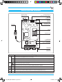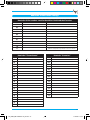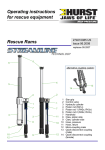
1
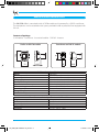
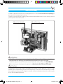
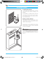
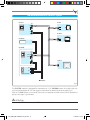
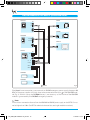
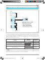
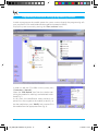
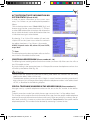
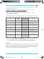
GSM Dialler
OH/GSM
Installer and User manual
24854401 - 03/09
OH_GSM_GB 24854401 03_09.indd 1
17/03/09 13:34
Use and Applications
OH/GSM telephone dialler is a device connected to the BPT bus line through a Hoasis+ home
automation system, which remotely allows only via SMS to:
• Activate scenarios (up to 16)
• Query and modify the status and temperature of the thermal zones (up to 20)
• Be advised in the event of technical alarms in the home automation system (up to 6) • Be advised in case of damage (outage) and reset of home electrical power
• Carry out a system check every 12/24 hours
• The device is also equipped with a normally open relay contact which can be used to activate
TH Bpt heat regulators designed for remote control or any other device set up for this purpose,
controlled through the opening or closing of a contact. The device must be programmed through the programming software.
m Important!
• The updated version of the programming software can be downloaded from the website:
www.bpt.it section “Download ” > “Software”.
The download password is OHSW2K7GSM
2
OH_GSM_GB 24854401 03_09.indd 2
17/03/09 13:34
Index
Use and Applications . . . . . . . . . . . . . . . . . Pag. 2
Safety warnings . . . . . . . . . . . . . . . . . . . . . . Pag. 4
Installer instructions
User instructions
General technical characteristics . . . . Pag. 6
Contents of package . . . . . . . . . . . . . . . . . . . . . . . . 6
Commands performed
by the User via SMS . . . . . . . . . . . . . . . . . . . Pag. 22
Insert a scenario . . . . . . . . . . . . . . . . . . . . . . . . . . . . . 22
Command customisation that can be performed via SMS . . . . . . . . . . . . . . . 22
Request information
on the system status . . . . . . . . . . . . . . . . . . . . . . . . . 22
SMS messages from OH/GSM dialler . . . . . . . . . . 24
Find out your remaining SIM credit . . . . . . . . . . . 25
SIM Card assembly . . . . . . . . . . . . . . . . . . . Pag. 7
Positioning of the device . . . . . . . . . . . . . Pag. 8
Assembly of the antenna . . . . . . . . . . . . . . . . . . . . 8
Module assembly on DIN rail . . . . . . . . . . . . . . . . 8
Terminal boards and connectors . . . . Pag. 9
Commissioning . . . . . . . . . . . . . . . . . . . . . . . Pag. 10
Connection diagrams . . . . . . . . . . . . . . . . Pag. 11
Reminder of the
Dialler settings . . . . . . . . . . . . . . . . . . . . . . . . Pag. 27
Programming of the dialler
through programming software . . . . . Pag. 14
Activate/deactivate
System status information . . . . . . . . . . . . . . . . . . . . 15
Create an address book . . . . . . . . . . . . . . . . . . . . . . 15
Special telephone numbers
in the address book . . . . . . . . . . . . . . . . . . . . . . . . . . 15
Thermal zones . . . . . . . . . . . . . . . . . . . . . . . . . . . . . . . 16
Technical alarms . . . . . . . . . . . . . . . . . . . . . . . . . . . . . 16
Scenarios . . . . . . . . . . . . . . . . . . . . . . . . . . . . . . . . . . . . 17
Programming of the dialler
through SMS. . . . . . . . . . . . . . . . . . . . . . . . . . . Pag. 18
Create an address book . . . . . . . . . . . . . . . . . . . . . . 18
Add a telephone number to the address book . . . . . . . . . . . . . . . . . . . . . . . . . 19
Modify a telephone number in the address book . . . . . . . . . . . . . . . . . . . . . . . . . . 19
Delete a telephone number
in the address book . . . . . . . . . . . . . . . . . . . . . . . . . . 19
Special telephone numbers
in the address book . . . . . . . . . . . . . . . . . . . . . . . . . . 19
Find out your remaining SIM credit . . . . . . . . . . . 19
Deactivate SMS reception
by a number in the address book . . . . . . . . . . . . . 20
Activate/Deactivate information
on the system status . . . . . . . . . . . . . . . . . . . . . . . . . 20
3
OH_GSM_GB 24854401 03_09.indd 3
17/03/09 13:34
Safety Warnings
m ATTENTION
• After removing the packaging, check the condition of the unit.
• The packaging items (plastic bags, expanded polystyrene, etc.) must not be handled by children as
they may be dangerous.
• Carefully read the instructions before starting installation. Perform work as specified by the manufacturer.
• Before connecting the equipment, make sure that the rating plate data corresponds to that of the
distribution network.
• An omnipolar switch, with contacts separated by at least 3mm, must be installed upstream on the
equipment, on the electric system of the building.
• The manufacturer declines all liability for any damage as a result of improper, incorrect or unreasonable use.
• Before performing any cleaning or maintenance operation, disconnect the equipment from the
power supply network by opening the system switch.
• In case of failure and/or malfunction of the device, detach it from the power supply and do not
tamper with it.
• Use original spare parts.
• Installation, programming, commissioning and maintenance of the product must only be performed by qualified technicians who have been properly trained in compliance with current
standards including compliance with accident prevention.
• Operate in sufficiently lighted areas that are conducive to health and use tools, utensils and equipment that are in good working order.
• Upon completion of installation, always check for correct operation of the unit and the system as a
whole.
• Do not install the device outdoors or in areas where it is exposed to seepage or splashes of water.
• Handle the device with care. It contains electronic parts that are fragile and sensitive to humidity.
• The electronic cards can be seriously damaged by discharges of static electricity. If they are to be
handled, wear suitable clothing and anti-static footwear, or at least, ensure static electricity has
been discharged by touching with the fingertip a metallic surface connected to the earth system
(e.g. the chassis of a household appliance).
• Weld the joints between wires to prevent false alarms caused by oxidation of the wires.
• The electrical system must comply with current standards in the country of installation.
• Failure to comply with the above instructions may compromise the unit’s safety.
• The installer must make sure that the information for the user, where applicable, is present on the
devices.
• Dispose of the unit in accordance with current standards.
4
OH_GSM_GB 24854401 03_09.indd 4
17/03/09 13:34
Installer instructions
OH_GSM_GB 24854401 03_09.indd 5
17/03/09 13:34
General technical characteristics
The OH/GSM dialler is contained inside a DIN70 module and is powered by a DIN35 transformer.
The components can be attached to the spaces provided inside any electrical box equipped with
DIN rail.
Contents of package
GSM Module - Transformer - Instruction booklet - DIN Rail - Antenna
64,5
64,5
7070
Weight
Container material
Degree of protection
Power supply
Standby consumption
Communication consumption
GSM module type
Operating temperature
Storage temperature
Relative Humidity
Weight
Container material
Degree of protection
Power supply
Secondary
72
72
45
45
Transformer on DIN 35 module
45
45
106
106
Dialler on DIN 70 module
3535
64,8
64,8
Dialler technical specifications
160 grams
PPOX (Polypropylene oxide)
IP 30
15 V AC or from the 12 V DC supply line
310 mA with 15 V AC –– 110 mA with 12 V DC
360 mA with 15 V AC –– 180 mA with 12 V DC
Modem GSM/GPRS Dual Band 900/1800 MHz
from +0 °C to +40 °C
-10 °C to +60 °C
< 90% without condensation
Transformer technical specifications 230VA - 15Vac
340 grams
encapsulated in epoxy resin
IP 00
230 Vac - 50Hz
15 V AC - 10 V A - 50 Hz
6
OH_GSM_GB 24854401 03_09.indd 6
17/03/09 13:34
SIM Card assembly
In order to operate, the device must be equipped with a SIM card, not included in the package,to
be inserted in the appropriate housing.
To do this, unscrew the two fastening screws and remove the dialler cover. Do this making sure that
you do pull out the antenna wire.
SIM card not included
SIM card housing
m ATTENTION !
• If the SIM card is new, prior to inserting it into the dialler, make a call by inserting it into a
mobile phone thus allowing the mobile telephone operator to register the card.
• The device requires that the SIM cards are activated only vocally and by SMS (No SIM Data!)
• Before carrying out the programming operation, deactivate the SIM card PIN code.
c ATTENTION !
The electronic cards can be seriously damaged by discharges of static electricity. If they are to be
handled, wear suitable clothing and anti-static footwear, or at least, ensure static electricity has been
discharged by touching with the fingertip a metallic surface connected to the earth system (e.g. the
chassis of a household appliance).
7
OH_GSM_GB 24854401 03_09.indd 7
17/03/09 13:34
Positioning of the device
Assembly of the antenna.
On the shell of the module, there is a seat for
the insertion of the antenna included in the
package.
If the module is installed inside a DIN box,
move the seat of the antenna into the appropriate additional hole on the shell, thus allowing its correct closure. Module assembly on DIN rail.
The module can be wall-mounted, with or
without terminal covers, using the DIN rail provided as shown in figure 1. Fig.1
Alternatevely it can be installed, with or without
terminal covers, in metal containers equipped
with DIN rail (EN 50022).
m ATTENTION
If the module is installed inside metal containers, use the optional antenna OH/ANT by
placing it outside the container as shown in
figure 2.
Fig.2
8
OH_GSM_GB 24854401 03_09.indd 8
17/03/09 13:34
Terminal boards and connections
RS 232 connector to
interface the module with a PC
Optional auxiliary
battery connector
Green LED
Voltage present
CN1
M2
Yellow LED
GSM transmission/reception
in progress
CN4
DL1
3
2
Red LED
On HOASIS systems
the LED is always on
Connection
for antenna
SIM Card
SIM Card housing
Jumper SW1
TAMPER disabled
CN5
B2
C
NO
TAMPER
TMP
LCK
DFT
BTL
LA
M1
BUS
LA
Terminals
BUS - LA
BUS - B2
M1
C, NO
TAMP
BUS
B2
C N0 TAMP
Jumper SW4
boot loader
Jumper SW3
default reset
Meaning
Terminal board for Bpt BUS Hoasis connection
Terminal board for BUS B2 BRAHMS connection (terminals not to be used in Hoasis systems)
Relay contact 12V 1A (normally open)
Terminal board for TAMPER contact connection (terminals not to be used in Hoasis systems)
Terminal board for earth connection
M2
SW1
SW2
SW3
SW4
SW1
SW2
SW3
SW4
Jumper SW2
address book protection
Terminal board for connection to power supply from power supplier
TMP
LCK
DFT
BTL
When the jumper is connected the tamper contact is disconnected
When the jumper is disconnected the address book cannot be modified via SMS
By powering the module without jumper the default configuration is reset
Boot-loader (jumper reserved for the Technical Service not to be removed)
9
OH_GSM_GB 24854401 03_09.indd 9
17/03/09 13:34
Commissioning
m ATTENTION
Before installing the module it is important to verify that there is an adequate radio receiving signal
from the device in the area where the device needs to be installed. To do this, simply insert the SIM in a mobile phone and check reception.
If reception is poor the device will have to be installed in another location with a better signal.
BPT S.p.A. declines all liability in the event of:
• failed transmission, failed reception, delayed transmission or delayed reception of SMS messages by the dialler, when these are due to the quality of the reception signal or to any other
problem related to the mobile telephone operator’s activities.
• charging cost on the dialler reamining SIM credit resulting from messages sent by the mobile
telephone operator or from other services carried out by the mobile telephone operator.
Once the module has been placed in the appropriate containers, as described in the previous
pages, proceed as follows:
• Ensure voltage has been removed to the system.
• Connect the terminal of the GSM module to the transformer.
• Connect the dialler to the BPT HOASIS home automation system through the BUS LA terminal.
• Connect the OH/B008 auxiliary battery to the appropriate connector (CN1).
• Connect the transformer to the electrical mains.
• Now restore voltage to the system.
• The lighting of the green LED indicates that the module is powered.
• The yellow LED, will remain on for a few seconds, during which the GSM device will verify mobile
reception.
If after a few seconds the yellow LED switches off the operation was successful. If, on the contrary, the yellow LED remains on this may indicate that there are GSM communication problems,
related to reception failure or SIM registration (see chapter “Montaggio della SIM Card”).
Once the installation has been completed the yellow LED will flash only in case of data transmission/reception on the GSM network.
. Note:
In Hoasis systems the red LED blinks.
10
OH_GSM_GB 24854401 03_09.indd 10
17/03/09 13:34
OH/GSM connection in a HOASIS system
OH/A.01
LA
OH/RI
M3
LA
LA
OH/MA
OH/B008
LA
+
–
OH/GSM
CN1
BUS LA
M1
BUS B2
M2
OH/T.01
15 V
230 V
TRANSFORMER
230Vac
Fig. 3
The OH/GSM module is designed for connection to a 12V OH/B008 battery that allows the transmission and reception of SMS messages in the event of an electrical power outage (Fig. 3).
With an OH/B008 battery a runtime of a few hours in reception and the transmission of approximately ten messages is guaranteed.
m ATTENTION
Connect the BPT home automation BUS to the terminals LA, not to the terminals B2.
11
OH_GSM_GB 24854401 03_09.indd 11
17/03/09 13:34
OH/GSM connection in a HOASIS system with OH/AS
OH/A.01
LA
OH/RI
M3
LA
LA
OH/MA
OH/GSM
LA
BUS LA
M1
BUS B2
OH/T.01
M2
OH/AS
–
20V +
LA
IN
M4
M2
LA OUT
–
BATT 1 +
–
BATT 2 +
M3
OH/B065
+
–
OH/B065
+
–
230Vac
Fig. 4
If the Hoasis home automation system contains an OH/AS emergency power supply the output 20
V DC of the power supplier will simply have to be connected to the input of the OH/GSM module (Fig. 4). With this setup, the OH/B008 battery is not necessary as the runtime of the OH/GSM
module is guaranteed by the OH/B065 emergency batteries.
. Note:
The maximum connection distance from the OH/A.01 or OH/AS power supply on the BPT BUS must
not be higher than 100m. (For BPT Bus electrical characteristics see single module instructions).
12
OH_GSM_GB 24854401 03_09.indd 12
17/03/09 13:34
OH/GSM connection to Bpt series TH programmable thermostats
OH/B008
+
–
OH/GSM
CN1
TH....
M1
TH450
NO
C
BUS LA
1
2
BUS B2
Bpt TH/450 - TH/350 - TH/125,
programmable thermostats
can be connected to this
contact, or any other device
remotely controlled through
the opening/closing of a relay.
M2
15 V
230 V
TRANSFORMER
230Vac
Fig. 7
The device is equipped with (terminals C, NO of terminal board M1) a normally open relay contact which can be used to activate TH Bpt thermal control systems designed for remote control
(TH/125 - TH/350 - TH/450) or any other device designed for this purpose, controlled through
the opening and closing of a contact. Function
SMS sent
by the User
Reply SMS
to the User
Closing of the dialler auxiliary relay contact
R E L E
ON
RELE ON
Opening of the dialler auxiliary relay contact
R E L E
OF F
RELE OFF
Closing of the dialler auxiliary relay contact for three
R E L E
seconds for activation of Bpt programmable thermostats
Relay status request
S TATO
TH
R E L E
RELE TH ON
RELE ON
RELE OFF
. Note:
The “RELE TH” command, sent to Bpt programmable thermostats, activates a specific programme.
Refer to the programmable thermostats manuals for more details. 13
OH_GSM_GB 24854401 03_09.indd 13
17/03/09 13:34
Programming of the dialler through programming software
In order to programme the module create the system structure through the programming software, acquire the GSM module identification code and proceed as follows.
Display the system structure by pressing the “Plant structure” menu.
Fig. 7
In order to add the GSM dialler to the system, press
“Connections - Network”.
Select the “GSM Module” icon from the window containing the module list and drag it to the desired switchboard (fig. 7).
At this point, the identification code, previously acquired, must be assigned to the module; to do this, select the module icon, press “Modify” and associate ID to
the module from the appropriate menu (fig. 8).
c
Fig. 8
14
OH_GSM_GB 24854401 03_09.indd 14
17/03/09 13:34
ACTIVATE/DEACTIVATE INFORMATION ON
SYSTEM STATUS (Check 12/24)
In order to receive information on the system status
every 12 or 24 hours on your mobile phone proceed as
follows.
Click on the drop-down menu “Check 12/24” (fig. 9) and
choose to activate the system check every 12, 24 hours
or select “Off” to deactivate this option; then choose the
day on which the check is to be performed and the time
in which the message is to be received.
By selecting 12 or 24, the GSM module will send a descriptive SMS on the system status to the first number in
the address book every 12 or 24 hours , for example:
HOASIS: Network status ON, alarms OK, zone AUTO,
temp. 20.0C
. Note:
The information on the heat regulation, refers to the first
one in the list of the dialler thermal zones.
c
Fig. 9
c
Fig. 10
CREATE AN ADDRESS BOOK (Phone number 01 - 10)
The following boxes are designed to contain the numbers (maximum 10) of the users that will use
the GSM module services.
By simply clicking in the appropriate boxes it will be possible to enter the telephone numbers that
will make up the address book (fig. 10).
m ATTENTION
• Always enter the appropriate international dialling code before the numbers that are being
added to the address book (+39 for Italy).
• The telephone numbers can contain up to 19 digits. In case of numbers containing more than19
digits and up to 24, it will be possible to programme the telephone numbers in the address book
via SMS, as described in the following chapters.
SPECIAL TELEPHONE NUMBERS IN THE ADDRESS BOOK (Phone number 11)
Messages sent by a specific telephone number can be sent to the first number in the address
book. To do this, enter the number from which the messages are sent in box 11 of the address book.
This function can be used to allow the informational messages from the specific mobile telephone
operator (for example information on the low credit status) to be sent to the first number in the address book; to do this it is necessary to know the number for “Centro Servizi” of the specific mobile
telephone operator. This number can be obtained by contacting Customer Service.
15
OH_GSM_GB 24854401 03_09.indd 15
17/03/09 13:34
For example:
Telecom Italia Mobile Vodafone Italia
+393359609600
+393359608000
+393492000200
THERMAL ZONES (Thermal zone 01 - 20)
Through the dialler it is possible to manage up to 20 thermal zones; to do this associate the thermal zones created
through programming software to the specific boxes contained in the programming window of the GSM Module.
By simply clicking in the appropriate boxes it will be possible to choose one of the available Thermal Zones from a drop-down menu (Fig. 11).
Fig. 11
TECHNICAL ALARMS (Alarm 01 - 06)
The GSM module can send a warning SMS in the event of an “Technical Alarm”; this alarm must
be programmed first through programming software, as follows:
Display the system structure by pressing the menu “Plant structure”; select the entry “Security” on
the left hand side of the screen and click on the icon “Alarms”; choose the icon of the alarm that
Fig. 12
16
OH_GSM_GB 24854401 03_09.indd 16
17/03/09 13:34
needs to be inserted, from the list of alarms displayed on
the right hand side of the screen, drag it inside the desired “Space” (fig. 12) and associate the created alarm to
one of the inputs of the system.
Press “Plant structure”, to return to the window displaying the system structure, select the icon for the GSM
module and access the module programming window
again by pressing “Modify”. By clicking on one of the 6
boxes reserved for the alarms the programmed alarms
will now be displayed in the list and it will be possible to
associate them to the available 6 alarm boxes (fig. 13).
Fig. 13
SCENARIOS (Scene 01 - 16)
It is possible to activate, through the dialler, up to 16
scenarios; to do this, associate the scenarios created
through programming software to the appropriate boxes contained in the GSM Module programming window. By clicking on one of the 16 “Scenarios” boxes on the
programming window choose one of the available scenarios from the drop-down menu (fig. 14).
Fig. 14
. Note:
• It is highly recommended (in order to make the use of the module easier for the User) to follow the
sequence of “Thermal zone” and “Scene” that have been inserted on OH/T terminal. • BPT declines all liability in case of transmission of SMS from the mobile telephone operator that
decrease the dialler remaining SIM credit.
• The User can take note of the main programmed parameters for his own benefit and as a written
reminder in case of future work on the system. 17
OH_GSM_GB 24854401 03_09.indd 17
17/03/09 13:34
Programming of the dialler via SMS
The OH/GSM dialler allows remote control and signalling functions via the receipt and sending of
SMS messages from and to the telephone numbers contained in the address book saved on the
internal memory of the dialler itself.
.Note: All the following settings can be programmed simply and intuitevely through
the use of programming software by connecting the system to a PC through the OH/SW
interface without SMS.
m Important!
• Before starting programming the address book via SMS make sure that the jumper SW2 (LCK)
is connected . With a disconnected jumper the programming of the address book can only be
performed through programming software.
• It is important to enter the appropriate international dialling code before the numbers that
are being saved in the address book (+39 for Italy) .
• The dialler, when purchased, can receive programming messages sent by any telephone
number. It is therefore advisable, once the programming of the address book has been completed, to disconnect the jumper SW2.
CREATE AN ADDRESS BOOK
The address book can be easily created via SMS messages structured in such a way that they carry
the information necessary for programming the module.
The address book can contain up to10 telephone numbers. Every programming SMS can send up
to 5 numbers to the address book. These SMS messages must have the following structure:
SMS n°1
P R O G N U M T E L 1 . first telephone number . second telephone number .
third telephone number . fourth telephone number . fifth telephone number .
SMS n°2
P R O G N U M T E L 2 . sixth telephone number . seventh telephone number .
eighth telephone number . ninth telephone number . tenth telephone number .
Example
If the GSM dialler must send or receive messages to/from only two numbers, the address book
programming message will have the follolwing structure:
P R OG N UM T E L 1 . + 3 9 3 4 7 1 2 3 4 5 6 7 . + 3 9 3 3 3 3 4 5 6 7 8 9 .
m Important!
The address book that is created via SMS will totally overwrite any pre-existing address
book.
18
OH_GSM_GB 24854401 03_09.indd 18
17/03/09 13:34
ADD A TELEPHONE NUMBER TO THE ADDRESS BOOK
If a telephone number needs to be added to the address book proceed as follows:
Example
If the address book contains 5 numbers, in order to add a sixth number, send the following message to the dialler:
MO D N UM T E L ( 6 ) + 3 9 3 3 3 8 8 8 8 8 8 8 .
This message overwrites a number in position 6 in the address book.
MODIFY A TELEPHONE NUMBER IN THE ADDRESS BOOK
If a telephone number in the address book needs to be modified proceed as follows:
Example
The message shown in the example allows to overwrite the number in position 2 of the address
book with a new one that will have to be written after the text “MODNUMTEL(2)”.
MO D N UM T E L ( 2 ) + 3 9 3 3 3 5 5 5 5 5 5 5 .
DELETION OF A TELEPHONE NUMBER IN THE ADDRESS BOOK
If a telephone number in the address book needs to be deleted proceed as follows:
Example
The message shown in the example allows to delete the number in position 5 of the address
book leaving the same position in the address book empty; the message has the following
syntax:
MO D N UM T E L ( 5 ) _ .
SPECIAL TELEPHONE NUMBERS IN THE ADDRESS BOOK
It is possible to allow the messages from a specific telephone number to be sent to the first
number in the address book.
This function can be used to allow the informational messages from the specific mobile telephone
operator (for example information on the credit) to be sent to the first number in the address book;
to do this it is necessary to know the number for “Service Center” of the specific mobile telephone
operator. This number can be obtained by contacting Customer Service.
The programming message will have the following syntax:
P R O G N U M G E S . number for telephone operator service centre .
In order to deactivate the function enter
P R OG N UMG E S . 0 .
FIND OUT YOUR REMAINING SIM CREDIT
In order to find out your remaining SIM credit a specifically structured SMS needs to be sent, depending on the specific telephone operator, preceded by the word “CREDIT”.
Some operators, for example Telecom Italia Mobile, require a message consisting of text + number;
in this case the message will have the following syntax:
C R E D I T “ P R E CRE S I N“4916 .
19
OH_GSM_GB 24854401 03_09.indd 19
17/03/09 13:34
Other operators, for example Vodafone Italia, require a simple number to be sent; in this case the
message will have the following syntax:
C R E D I T 1 “ C A L L “+4 04 .
DEACTIVATE SMS RECEPTION BY A NUMBER IN THE ADDRESS BOOK
The default settings allow an event to be reported to all users through an SMS. However it is possible to prevent some numbers from receiving these messages.
Example
If you wish to prevent the fifth number in the address book from receiving SMS the programming
message will have the following syntax:
P R O G S M S ( 5 ) OFF .
In order to reactivate SMS reception by the number the programming message will have the following syntax:
P R O G S M S ( 5 ) ON .
. Note:
It is possible to deactivate SMS reception by a certain number only through programming via
SMS.
ACTIVATE/DEACTIVATE INFORMATION ON THE SYSTEM STATUS
It is possible to receive information on the system status on your mobile phone every 12 or 24
hours.
Example
If you wish to receive information on the system status every 12 hours the programming message
will have the following syntax:
C H E C K ( 1 2 ) ON .
If you wish to receive information on the system status every 24 hours the programming message
will have the following syntax:
C H E C K ( 2 4 ) ON .
In order to deactivate this function the programming message will have the following syntax:
CHE CK ( 1 2 ) OFF .
or
CHE CK ( 2 4 ) OFF .
. Note:
• BPT declines all liability in case of transmission of SMS sent by the mobile telephone operator that
decrease the remaining credit on the dialler SIM.
• The User can take note of the main programmed parameters for his own benefit and as a written
reminder in case of future work on the system. 20
OH_GSM_GB 24854401 03_09.indd 20
17/03/09 13:34
User instructions
OH_GSM_GB 24854401 03_09.indd 21
17/03/09 13:34
Commands performed by the User via SMS
The Users whose numbers have been inserted in the address book can, through SMS messages,
remotely control their Hoasis home automation system or request information on the status of the
system.
INSERT A SCENARIO
If (for example), during programming, through programming software, a scenario identified as
“NIGHT”, has been created, in order to activate that scenario an SMS with the following syntax will
have to be sent to the dialler:
S C ENAR I O “ N I GHT “
Once the command has been performed, the dialler will send a confirmation message to the user
that has activated the scenario:
HOASIS: “NIGHT” on
CUSTOMISATION OF COMMANDS PERFORMED VIA SMS
The SMS messages that are sent to the GSM module can be customised, allowing them to be
memorised and subsequently transmitted more easily, or written in a different language from the
default one (Italian).
The customisation can be carried out using the SMS messages described in the coloumn highlighted in the table (customised SMS sent by the User), where in place of the word “Comment”, a
customised text can be added.
For instance, in order to activate the scenario “NIGHT” previously created through programming
software the following SMS can be used:
1 < I WAN T T O A C T I V A T E T H E S C E N A R I O > “ N I G H T “
that will receive the confirmation HOASIS: “NIGHT” on
Or in order to find out the status of the system the following SMS can be sent:
4 < W HA T
I S THE S TATUS OF THE
S I S T EM? >
that will receive the reply
Hoasis: Network status ON, alarms OK, zone AUTO, temp. 22,6C
REQUEST INFORMATION ON THE STATUS OF THE SYSTEM
In order to find out the general status of the system, send an SMS with the following syntax:
S TATO I MP I ANTO
A reply message will be received describing the status of the system, for example:
HOASIS: Network status ON, alarms OK, zone MAN, temp. 20,5C
22
OH_GSM_GB 24854401 03_09.indd 22
17/03/09 13:34
Or it is possible to request information on the status of a specific “Thermal zone” previously created
through programming software.
In the following example information is requested on a zone identified as “living room”
S T A T O C L I M A “ L I V I N G R OOM “
A reply message will be received describing the status of the specific zone, for example:
Climate “living room” AUTO 20,8C
The following table shows a list of all possible messages that can be sent to the dialler in order to
perform operations remotely or to receive information on the status of the system. Function
SMS sent
by the User
customised SMS
sent by the User
Scenario activation
Scenario
“scenario name”
1 <Comment>
“scenario name”
Setting of thermal
zone in AUTO mode
Clima “zona name”
2 <Comment>
AUTO
“zona name” AUTO
Setting of thermal zone in
Clima “zona name”
2 <Comment>
Manual mode for example at
MAN.20.
“zona name” MAN.20.
20°C temperature
Reply SMS
to the User
HOASIS:
“scenario name” on
Climate “zona name”
AUTO 23,5C
Climate “zona name”
MANUAL 20.0C
Setting of thermal zone
in OFF mode
Clima “zona name”
OFF
2 <Comment>
“zona name” OFF
Climate “zona name”
OFF 23,2C
Thermal zone status request
Stato clima
“zona name”
3 <Comment>
“zona name”
Climate “zona name”
AUTO/MANUAL/OFF 20,8C
System status request
Stato impianto
4 <Comment>
HOASIS: Network status ON,
alarms OK, zona MAN,
temp. 20,5C
Request for activation/deactivation of SMS on system
status (every 12 or 24 hours) Check (12/24)
ON/OFF
5 <Comment>
(12/24) ON/OFF
Check (12/24) ON/OFF
In SMS containing “zona name” or “scenario name”, write the name of the thermal zone or
scenario, in exactly the same way as indicated in the programming software.
. Note:
In the event of a text message requesting the system status or heating zone status, the controller
will give a system or zone temperature between 10.0°C and 35.0°C even when the system or zone
temperature is lower or higher than this interval. For example, if the temperature in the heating zone
is 8.5°C, the controller will respond with a zone temperature of 10.0°C.
23
OH_GSM_GB 24854401 03_09.indd 23
17/03/09 13:34
The device is equipped with a relay contact that can be used to activate TH Bpt thermal control
systems designed for remote control (TH/125 - TH/350 - TH/450) or any other device designed
for the same purpose, controlled through the opening or closing of a contact.
Function
SMS sent by the User
Reply SMS
to the User
Closing of the dialler auxiliary contact relay
R E L E
ON
RELE ON
Opening of the dialler auxiliary contact relay
R E L E
OF F
RELE OFF
Closing of the dialler auxiliary contact relay for 3 seconds
R E L E
for activation of Bpt programmable thermostats
S TATO
Relay status request
TH
R E L E
RELE TH ON
RELE ON
RELE OFF
. Note:
The “RELE TH” command, sent to Bpt programmable thermostats, activates a specific programme.
For more details refer to the programmable thermostats manuals.
SMS MESSAGES FROM OH/GSM DIALLER
The dialler sends informational messages on the control unit status to the numbers contained in
the address book.
For instance, in the event of a technical alarm, the dialler sends a message indicating the type of
technical alarm occurred followed by the date and time of the event. Messages on technical alarms and network outage and reset, will be sent to all numbers contained
in the address book (max 10). Informational SMS messages on “control unit status” sent by the dialler to the User
Event
SMS Message received
Technical Alarm
Technical alarm “alarm name” <25-05-07><18:35>
Electrical power outage
Electrical power reset
Reset Network <28-05-07><20:35>
System status (every 12/24 hours)
Network Fault <28-05-07><19:35>
HOASIS: Network status ON, alarms OK,
zone AUTO, temp. 20.0C
Furthermore, the dialler, if correctly programmed, will also send all messages from the telephone
operator service centre to the first valid number in the address book, indicating the credit deadline. 24
OH_GSM_GB 24854401 03_09.indd 24
17/03/09 13:34
FIND OUT YOUR REMAINING SIM CREDIT
In order to find out the remaining credit of your SIM it is necessary to send an SMS specifically structured depending on your telephone operator preceded by the word “CREDIT”.
Some operators, for example Telecom Italia Mobile, require a message consisting of text +
number;
the message will have the following syntax:
CR ED I T “ P R E CR E S I N “ 4 9 1 6 .
Other Operators, Vodafone Italia for example, require a simple number to be sent. The message will
have the following syntax:
CR ED I T 1 “ CA L L “ + 4 0 4 .
.Note:
• Through SMS messages it is possible to perform only one command for each message (activate
only one scenario, change the status of the thermal zone).
• The confirmation message, depending on the telephone operator, could take a few minutes.
• BPT declines all liability in case of transmission of SMS by the mobile telephone operator that
decrease the dialler remaining SIM credit.
• If a message is sent by a number not present in the address book in order to activate one of the
services the following reply will be received: Telephone number does not correspond to user.
• The messages sent and received by the GSM will be automatically deleted to prevent the SIM
card memory from running out.
25
OH_GSM_GB 24854401 03_09.indd 25
17/03/09 13:34
26
OH_GSM_GB 24854401 03_09.indd 26
17/03/09 13:34
Reminder of the Dialler settings
Reminder of the numbers saved in the address book and their location
Position
Number
User name
01
02
03
04
05
06
07
08
09
10
11
Mobile Telephone Operator “Service Center”
N°
01
02
03
04
05
06
07
08
09
Reminder “Thermal zone”
Zone name
10
11
12
13
14
15
16
17
18
19
20
N°
01
02
03
04
05
06
07
08
09
Reminder “Scenarios”
Scenario Name
10
11
12
13
14
15
16
27
OH_GSM_GB 24854401 03_09.indd 27
17/03/09 13:34
BPT S.p.A.
Via Cornia, 1
33079 Sesto al Reghena-PN-Italy
[email protected] – www.bpt.it
OH_GSM_GB 24854401 03_09.indd 28
17/03/09 13:34