1
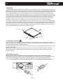
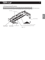
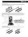
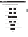
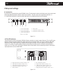
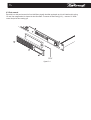
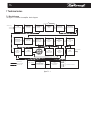
E
L
Digital Audio Amplifier
for Professional Applications
User Manual
V 1.5 (24/09/2007)
1
Table of contents
Important safety instructions................................................................................................................................2
Warning notices................................................................................................................................................................2
Safety rules.......................................................................................................................................................................3
Speaker demage..............................................................................................................................................................3
Speaker output shock hazard...........................................................................................................................................3
Introduction......................................................................................................................................................................4
More sound and less weight.............................................................................................................................................4
Superior Sound-Sonic Accuracy.......................................................................................................................................4
Totally Digital with High Reliability.....................................................................................................................................4
The L Series......................................................................................................................................................................4
The Show Always Goes On..............................................................................................................................................4
Chapter 1: Installation and operation.............................................................................................................5
1.1 Unpacking...................................................................................................................................................................5
1.2 Mounting.....................................................................................................................................................................6
1.3 Operating precautions................................................................................................................................................6
1.4 AC Mains connection..................................................................................................................................................6
1.5 Buildings and setting DSP module(s).........................................................................................................................7
1.6 Mounting DSP module(s)............................................................................................................................................8
1.7 Removing DSP Module(s)..........................................................................................................................................8
1.8 Dip switch settings......................................................................................................................................................9
1.9 Connecting inputs...................................................................................................................................................10
1.10 Connecting outputs.................................................................................................................................................11
Chapter 2: Setup and settings..........................................................................................................................12
2.1 Introduction...............................................................................................................................................................12
2.2 The LED indicators...................................................................................................................................................12
Chapter 3: Protection..............................................................................................................................................13
3.1 Turn-On/Turn-Off muting...........................................................................................................................................13
3.2 Short circuit protection..............................................................................................................................................13
3.3 Thermal protection....................................................................................................................................................13
3.4 DC fault protection....................................................................................................................................................13
3.5 Input/Output protection.............................................................................................................................................13
Chapter 4: User maintenance...........................................................................................................................13
4.1 Cleaning....................................................................................................................................................................13
4.2 Service......................................................................................................................................................................13
4.3 Dust removal.............................................................................................................................................................14
Chapter 5: Warranty................................................................................................................................................15
Chapter 6: Assistance............................................................................................................................................15
Chapter 7: Technical notes.................................................................................................................................16
7.1 Block diagram...........................................................................................................................................................16
7.2 Technical specifications............................................................................................................................................17
E
2
Important safety instructions
CAUTION
RISK OF ELECTRIC SHOCK
DO NOT OPEN
!
CAUTION: To reduce the risk of electric shock, do not remove the cover. No user-serviceable parts inside.
Refer servicing to qualified service personnel.
E
KEEP THIS INSTRUCTIONS
SAFEGUARDS: Electrical energy can perform many useful functions. This unit has been engineered and
manufactured to assure your personal safety. Improper use can result in potential electrical shock or fire
hazards. In order not to defeat the safeguards, observe the following instructions for its installation, use and
servicing.
NOTES: This equipment has been tested and found to comply by Competent Body (Directive 89/336/EECEMC) pursuant to the product family standard for audio professional use:
EN 55103-1 and EN 55103-2 standard ); EN61000- 3 - 2, EN 61000 - 3 - 3.
This is a Class A product. In a domestic environment this product my cause radio interferences in which case
the user may be required to take adequate measures.
This equipment has been tested and found to comply by Notified Body (Directive 73/23/EEC L.V) pursuant to
the audio apparatus safety requirements: Standard EN 60065.
Warning notices
Location
Install the amplifier in a well-ventilated location where it will not be exposed to high temperature or humidity.
Do not install the amplifier in a location that is exposed to direct rays of the sun, or near to hot appliances or radiators.
Excessive heat can adversely affect the cabinet and internal components. Installation of the amplifier in a damp or
dusty environment may result in malfunction or accident.
Precautions regarding installation:
Placing and using the amplifier for long periods on heat-generation sources will affect performances. Avoid placing the
amplifier on heat-generating sources. Install this amplifier as far as possible from tuners and TV sets. An amplifier
installed in close proximity to such equipment may cause noise or degradation of the picture.
WARNING: To prevent fire or electric shock
!
The ventilation openings must not be impeded by any items as newspapers, table-clothes, curtains etc; keep
a distance of at least 50cm from the front and rear ventilation openings of the amplifier.
!
do not expose this equipment to rain or moisture.
!
Apparatus shall not be exposed to dripping or splashing and no objects filled with liquids, such as vases, shall
be placed on the apparatus”.
3
Safety rules
This device must be powered exclusively by earth connected mains sockets in electrical networks compliant to the IEC
364 or similar rules.
Is absolutely necessary to verify this fundamental requirement of safety and, in case of doubt, require an accurate
check by a qualified personnel.
The constructor cannot be considered responsible for eventual damages caused to persons, things or data for the
missing of accurate earth link.
!
Before powering this device verify that the amplifier is supplied with the correct voltage rating.
!
Verify that your mains connection is capable to satisfy the power ratings of the device.
!
Do not spill water or other liquids into or on the unit.
!
Do not use this unit if the electrical power cord is frayed or broken.
!
Do not remove the cover. Removing the cover will expose you to potentially dangerous voltage.
!
No naked flame sources such like lighted candles should be placed on the amplifier
!
Provide sectioning breaker between mains connections and apparatus. Suggested device is 10A/250Vac
(230Vac mains voltage) or 16A/250Vac (110Vac mains voltage), C or D curve, 10KA.
Contact the authorized center for ordinary and extraordinary maintenance.
Speaker damage
The DIGAM series amplifiers are among the most powerful professional amplifiers available and are capable of
producing much more power than many loudspeakers can handle. It is the user's responsibility to use suitable
speakers with the amplifier and to use them in a sensible way that will not cause damage.
Powersoft will not be responsible for damaged speakers. Consult the speaker manufacturer for power-handling
recommendations.
Even if you reduce the gain using the amplifier's front panel attenuation controls, it is still possible to reach full output
power if the input signal level is high enough.
A single high-power crescendo can damage high-frequency drivers almost instantaneously, while low-frequency
drivers can usually withstand very high, continuous power levels for a few seconds before they fail. Reduce power
immediately if you hear any speaker "bottoming out" - harsh pops or cracking distortion that indicate that the speaker
voice coil or diaphragm is striking the magnet assembly.
Powersoft recommends that you use amplifiers of this power range for more headroom (cleaner sound) rather than for
increased volume.
Speaker output shock hazard
A DIGAM amplifier is capable of producing hazardous output voltages. To avoid electrical shock, do not touch any
exposed speaker wiring while the amplifier is operating.
This manual contains important information on operating your DIGAM amplifier correctly
and safely. Please read it carefully before operating your amplifier. If you have any
questions, contact your Powersoft dealer.
E
4
1 Introduction
Powersoft is a leading company in the field of high efficiency audio power management. The totally new Powersoft's
DIGAM (DIGital AMplifier) technology has changed the way the world looks at professional audio amplification. No
other amplifiers come close for applications demanding high power and long term reliability. Thanks to amazing
reductions in heat output along with reductions in weight and the specific high output power, DIGAM amplifiers can be
used in an unlimited range of applications such as concert touring, opera houses, theatres, churches, cinema, theme
parks, television sound stages and industrial applications.
More sound and less weight
Compared to a conventional amplifier, Powersoft DIGAM technology offers very high efficiency and delivers more
power to the loudspeakers with much reduced heat dissipation. This greater efficiency enables dimensions, weight and
power consumption to be reduced. The output stages of the amplifiers typically run at 95% efficiency, dissipating only
5% of the input energy as heat.
One of the most interesting characteristics is that DIGAM's efficiency is almost independent of output level.
Conventional amplifiers achieve their best efficiency only at full rated power output. Since standard music has an
average power density of 40% of the maximum level, conventional amplifiers can easily generate 10 times more heat
than DIGAM for the same volume of sound.
Superior Sound-Sonic Accuracy
Crystal-clear highs, and a tight, well-defined low end: the most accurate reproduction of an audio signal. Patented
design features ensure very high performance in parameters such as distortion, frequency response, slew rate, power
bandwidth and dumping factor.
Totally Digital with High Reliability
The DIGAM series is based on PWM technology that has been used for 30 years or more in power supplies and
inverters. PWM provides high reliability, small size, low weight and high efficiency. A PWM converter works as a high
frequency sampler, converting the variable amplitude (audio) signal into an impulse sequence with average value
equal to the audio input.
DIGAM amplifiers use very high sampling frequencies to obtain high performances across the audio band. Powersoft
holds several patents on the DIGAM technology.
The L Series
The more important characteristics of the L series are the compact dimensions, the light weight and the ease of use.
Moreover for the L series amplifiers are upgradable with DSP and remote control.
The Show Always Goes On
DIGAM Series is completely protected against every possible error in operation and is designed to work under every
condition. It gives you maximum power with maximum safety and increases long-term reliability. Anticipating potential
problems at the design stage means your show always goes on!
E
5
1 Installation and operation
1.1 Unpacking
Carefully open the shipping carton and check for any noticeable damage; the figure below shows the view of the packing.
Every Powersoft amplifier is completely tested and inspected before leaving the factory and should arrive in perfect
condition. If you find any damage, notify the shipping company immediately. Be sure to save the carton and all packing
materials for the carrier's inspection.
E
manual
mains cable
amplifier
figure 1.1
6
1.2 Mounting
All DIGAM amplifiers are previewed for the standard 19" rack mounting; there are four front panels holes and two rear
lateral holes. The amplifiers must be fixed into rack in both sides, back and frontal, to avoid mechanical damages. Your
DIGAM amplifier uses a forced-air cooling system to maintain a low, even operating temperature. Drawn by an internal
fan, air enters through the slots in the front panel and courses over and through components. The DIGAM series
amplifiers feature an "intelligent" variable-speed DC fan which is controlled by heat sink temperature sensing circuits:
the fan speed will increase only when the temperature of the heat sink requires it, which keeps fan noise to a minimum
and helps cut dust accumulation inside. Under extreme thermal load, the fan will force a very large volume of air
through the heat sink. If the heat sink gets too hot, its sensing circuit will reduce the output power. If the amplifier
overheats, another sensing circuit shuts down its circuit to cut off power until it cools to a safe temperature.
The exhaust cooling air is forced out through the rear of the chassis (see figure 1.2.1), so make sure there is enough
space around the sides of the amplifier to allow the air to escape. If it is rack mounted, make sure the exhaust air can
flow without resistance. If you are using a rack with closed backs, there must be at least one standard rack space of
opening in the front of the rack for every four amplifiers. Amplifiers may be stacked directly on top of each other (no
space needed between units), starting from the bottom of the rack.
mounting holes
mounting holes
air flow
figure 1.2.1
1.3 Operating Precautions
Make sure the AC mains voltage is correct and is the same as that printed on the cover of the amplifier. Damage
caused by connecting the amplifier to improper AC voltage is not covered by the warranty. Make sure the power switch
is off before making any input or output connections.
It is always a good idea to have the gain controls muted during power-up to prevent speaker damage if there is a high
signal level at the inputs.
Whether you buy them or make them, use good-quality input and speaker cables. Most intermittent problems are
caused by faulty cables. Use good-quality connectors and wire, along with good soldering technique, to ensure
troublefree reliability.
1.4 AC Mains connection
Warning: before connect the mains be sure that the amplifier is set up to the correct mains voltage.
The AC Mains connection is made via the IEC type connector on the rear side of the panel. The figure below shows
the connection to the amplifier. Be sure that your AC mains power source has the requirements indicated in
this manual. It is important to connect the ground for safety, do not use adapters that disable the ground.
GROUND
MAINS
figure 1.4.1
E
7
1.5 Building and setting DSP module(s)
Warning: before removing the cover, turn off the power switch and unplug the mains cable.
The Digam L series has otional DSP modules for additional sound effects. To mount or unmount theDSP modules remove
the cover; you can mount this modules on the 72-pin SIMM sockets as showed in the figure below.
DSP modules
E
SW104 DIP SWITCH
DSP socket for CH1 and CH2 channel
SW302 DIP SWITCH
(only for LQ model)
SW103 DIP SWITCH
(only for LD model)
SW102 DIP SWITCH
DSP socket for CH3 and CH4 channel (only for LQ model)
figure 1.5.1
8
1.6 Mounting DSP module(s)
The correct operations for mounting a DSP module is shown in the figures below; the first operation is to insert the module
vertically with the component side shown in the figure 1.6.2 in the caveat of the SIMM socket with a weak pressure, then
rotate the module until the fingers have jammed it (figure 1.6.3).
figure 1.6.1
figure 1.6.2
note: if you mount 2 DSP module you must connect the J6 contact and J7 contact at the rear side of the
correspondent DSP module (see the figure1.6.4); the figure 1.6.5 shows the exact point where you must solder
the wire. This operation is necessary to syncronize the channels 1-2 with the channels 3,4 sampling clock if the
DSP board is a version up to DGMDSPA13; from version 14 there is no need of external sync for the DSP
boards
DSP module for channel 1-2
wire
J6 contact
wire
J7 contact
DSP module for channel 3-4
figure 1.6.3
figure 1.6.4
1.7 Removing DSP module(s)
The correct operations for mounting a DSP module is shown in the figures below; first, open the fingers; then rotate the
module in the vertical position and extract it.
figure 1.7.1
figure 1.7.2
9
1.8 Dip switch settings
The figure below shows the dip switch settings for any aperating mode of the amplifier
DSP NOT INSTALLED
CH1-2
CH3-4(LQ ONLY)
ON
ON
1
2
3
1
4
2
3
4
E
SW102
SW302
CH1-2
CH3-4(LQ ONLY)
DSP INSTALLED
ON
ON
1
2
3
1
4
SW102
2
3
4
SW302
CH3-4=OUTSUB DSP CH1-2 (LQ ONLY)
DSP ON CH1 NEEDED
ON
ON
ON
1
2
3
1
4
SW102
2
3
1
4
SW302
2
3
4
SW103
CH3-4=CH1-2 (LQ ONLY, SET SW102 AS NEEDED
FOR DSP INSTALLED OR NOT)
ON
ON
1
2
3
1
4
SW302
2
3
4
SW103
CN303, CN403 AS SPARE OUTPUTS CH1-2 (LD ONLY)
ON
1
2
3
4
5
6
7 8
SW104
CN303, CN403 AS EXTERNAL SUB OUT (LD ONLY, DSP NEEDED)
ON
1
2
3
4
5
6
7 8
SW104
figure 1.8.1
10
1.9 Connecting Inputs. Input connections are made via the 3-pin XLR-male type on the rear side of the amplifier. The
connection for "LQ" model (four channels) is shown in figure 1.7.1; on the right side of the figure is shown the polarity of
the XLR connector.
IN(+)
GND
IN(-)
figure 1.9.1
The figure below shows the connection of analog input for balanced and unbalanced line. You can use both configuration,
but you must consider that unbalanced long line can introduce noise in the audio system. The Link switch located in the
rear panel is for direct paralleling the rear input connectors. You can use the remaining input connector to carry signal to
other amps.
GND
SHIELD
IN(+)
IN(-)
IN(+)
/
Unbalanced input
Balanced input
figure 1.9.2
TURN T
O
OUT CH2/DSP
to CH2 input
of other
amplifier or
sub-audio
output
OUT CH 1/DSP
to CH1 input
of other
amplifier or
sub-audio
output
XLR
1 = GND
2 = HOT
3 = COLD
IN
CH 2
CH2 input
figure 1.9.3
OUT LINK ON OFF
“WARNING
To reduce The Risk of Fire
or Electric Shock, do not
Expose this Apparatus
to Rain or Moisture”
L
L
K
OC
CLASS2 WIRING
TURN T
O
K
OC
OUT: 1+ 1- BRIDGE: 2+ 2-
In the "LD" model (two channels) the input connections are in the right side of the panel; the remaining input connections
are connected in parallel with the first ones with the default settings and you can use it as input connections with other
amplifiers; in the models with DSP built-in (optional), these connectors function as outputs of sub channel of DSP board
(see figure 1.7.3).
OUT
CH 1
IN
CH1 input
11
1.10 Connecting Outputs
Warning: there are lethal voltages at the loudspeaker connectors when the amplifier is turned on. To prevent any
damages turn the amplifier off before connecting the loudspeker
Output connectors are made via neutrik speakon connectors. Consult the wire gauge chart to find a suitable wire gauge to
minimize power and damping factor losses in the speaker cables. For each device the 1+ pin of speakon connector have
to be considered the positive output of the channel; the 1- pin of speakon connector have to be considered the negative
output of the channel.
Note: Channel B is always polarity reversed output stage, but polarity compensated by feeding the minus pins of the
channel B output with the output voltage. Channel A is connected in the polarity mode. By having channel A and B
operating in opposite polarity, the energy storage in the power supply is more efficient. This is significant for signals below
100Hz (sub bass etc.) and improves the power bandwidth.The outputs can also work on bridge mode, see the figure 1.8.2
for the connections in this mode. Be sure to use balanced inputs on all measurement equipment (also oscilloscope
probes) in your testing bench.
figure 1.10.1
The figure below shows the connection of the speakons to the speakers. Pay attention to the position of the link switch; in
stereo mode turn the position to "off", in bridge mode turn to "on" and turn the gain control of each couple of channels at
the same level. In bridge mode the dots lines indicate an alternative connection of the speaker.
SPEAKON CH1
SPEAKON CH3
2+
1-
CH1
21+
2+
+
1-
CH3
-
21+
SPEAKON CH2
121+
-
SPEAKON CH4
2+
CH2
+
2+
+
1-
CH4
-
21+
+
LINK SWITCH
stereo mode
SPEAKON CH3
SPEAKON CH1
2+
2+
CH1
121+
2+
CH2
121+
+
-
121+
+
-
CH3
2+
CH4
121+
SPEAKON CH4
SPEAKON CH2
bridge mode
figure 1.10.2
+
+
-
E
12
2 Setup and settings
2.1 Introduction
8
The figure below shows the front panel of DIGAM L Series. The front panel controls and indicators give to the user the total
control and detailed information about the status of the amplifier. The gain control use a logarithmic scale from to +32dB. Read carefully the instructions below that help you to manage the functions of the amplifier.
CLIP
CLIP
-6dB
-6dB
-18dB
-18dB
SIGNAL
SIGNAL
TEMP
READY
A
F B
READY
C G
R
I
O
TEMP
D
E
A - Gain control channel 1
B - Gain control channel 2
C - Gain control channel 3*
D - Gain control channel 4*
E - Power switch
F - LED indicators channel 1 and 2
G - LED indicators channel 3 and 4*
* only for "LQ" models
figure 2.1.1
2.2 The LED indicators
The figure below shows the front panel of DIGAM L Series. and refers to a single couple of channels. The clip LED, when
lighting, indicates the clipping state for the output stage of the correspondig channel. The signal, -18dB and -6dB LEDs
operate as V-meter and the signal LED is lighted when the signal is present in the input stage of the correspondent
channel. The "ready" LED, when lighted, indicates that the startup time after power-on is finished and the amplifier is
ready to use. The "temp" LED, when lighted, indicates that the output stage of the corresponding channel is reducing the
output power due to an over-heated state.
CLIP
-6dB
-18dB
SIGNAL
TEMP
READY
A B C D E
A - Clipping and protection indicator channel 1 (or 3)
B - -6dB output level indicator channel 1 (or 3)
C - -18dB output level indicator channel 1 (or 3)
D - signal presence indicator channel 1 (or 3)
E - "Ready" indicator
F G H I J
F - Over-temperature indicator
G - Signal presence indicator channel 2 (or 4)
H - -18dB output level indicator channel 2 (or 4)
I - -6dB output level indicator channel 2 (or 4)
J - Clipping and protection indicator channel 2 (or 4)
figure 2.1.2
13
3 Protection
3.1 Turn-On/Turn-Off muting
For about four seconds after turn-on, and immediately at turn-off, the amplifier outputs are muted.
3.2 Short circuit protection
A short circuit protection system safeguards the amplifier's output transistors under short circuits and other stressful loads.
It is completely inaudible when inactive. In case of short circuit, the red LED will be lightened. The amplifier reset protection
mode himself with 2 seconds of retry cycle.
E
3.3 Thermal protection
A DIGAM amplifier uses a continuously variable speed fan to assist cooling (the fan speed changes in response to the
amplifier's cooling needs). If the heatsink temperature reaches approximately 75°C, the "TEMP" LED lights up, and the
otput power is reduced to prevent damages to the output stage. If the temperature is more than 85°C the thermal sensing
circuitry will mute each power section channels. Once the heatsink has cooled down, the amplifier will automatically
unmute, but the LED will be unlighted at 75°C. It will be possible to reduce the temperature reducing the output power.
3.4 DC fault protection
If DC or excessive subsonic energy appears at a channel output, an instantaneous protection circuit will mute both
channels of the amplifier. The amplifier shutdown is used instead off of speaker relays, thereby improving the damping
factor and reliability of the DIGAM amplifiers.
3.5 Input/Output protection
An ultrasonic network decouples RF from the outputs and keeps the amplifier stable with reactive loads.
4 User maintenance
4.1 Cleaning
Disconnect the amplifier from the AC main source first; use a soft cloth and mild non-abrasive solution to clean the
faceplate and chassis.
4.2 Service
There are no user-serviceable parts in your DIGAM amplifier. Refer servicing to qualified technical personnel.
In addition to having an in-house service department, Powersoft supports a network of authorized service centers. If your
DIGAM amplifier needs repair, contact your Powersoft dealer or distributor, or contact the Powersoft Technical Service
department, to obtain the location of the nearest authorized service center.
14
4.3 Dust removal
Especially in a dusty environment, the front side filters clog with dust after prolonged use, this will interfere with cooling.
You may use compressed air to remove the dust from filters. To remove air filters see fig(4.3.1) , unscrew n°3 M3X6
screws and pull off the covering grill.
E
filter
figure 4.3.1
15
5 Warranty
Powersoft prides itself on the quality and reliability of its products that are designed and manufactured to meet the highest
quality standards. We are also proud of the great care we assure to our customers. We are confident that you will never
have a need to take advantage of this warranty, but in the unlikely event of a failure or deviation in performance, we'll do
our very best to get you swiftly back in business.
Powersoft amplifiers warranty is calculated from the original date of purchase from an Authorized Powersoft Dealer. During
this time, if your amplifier fails for any defect in components and/or labour under a correct and regular use, it will be
repaired or, at our sole opinion, replaced without any charge a part for the transport expenses to return the unit at
Powersoft premises. The repaired/replaced amplifier will be finally returned to you with the original shipping carton at our
charge.
The Warranty conditions will not be applied in case the amplifier has been ulteriorly damaged by repair attemps,
inadequate or poor packaging, any kind of improper use/maintenance (overvoltage, incorrect connection, use with wrong
or faulty associated equipment or accessories, exposure to rigid weather conditions, excess moisture, etc…).
Warranty terms will not be consider for any unit where the serial number has been removed and or it is not clearly
readable. Powersoft is not responsible for any incidental or consequential damages; the responsibility is limited to the
product itself. Powersoft reserves the right to make changes or improvements in design or manufacturing without
assuming any obligation to change or improve product previously manufactured.
6 Assistance
The local Powersoft distributor/reseller will be glad to support you in case of fault or for any additional information.
If you cannot contact your local distributor/reseller, please mail to [email protected]
Do not ship any unit to Powersoft for Factory Service before having had the Powersoft authorization.
E
16
12
7 Technical notes
7.1 Block diagram
The figure 7.1.1 shows the amplifier block diagram.
SIGNAL INPUT
LMAIN
INPUT EMI FILTER
DGMCONTROL
DIFFERENTIAL
AMPLIFIER
LFRONT
VOLUME CONTROL
& DISPLAY
DGMDSPA
OPTIONAL DSP
BOARD
DGMCONTROL
CLOCK GENERATOR
AND DIVIDER
DGMCONTROL
MODULATOR
DGMCONTROL
BUFFER & LEAD
TIME CONTROL
LMAIN
OUTPUT STAGE
DRIVER
LMAIN
FRONT LED
CONTROL
LMAIN
FAN CONTROL
DGMCONTROL
LIMITER CIRCUIT
DGMCONTROL
ERROR AMPLIFIER
LMAIN
OUTPUT HALF
BRIDGE POWER
STAGE
LMAIN
OUTPUT LOW PASS
FILTER
OUTPUT SIGNAL
LMAIN
DRIVER FOATING
POWER SUPPLY
LMAIN
PROTECTION
CIRCUIT
LMAIN
EMI FILTER
+85V
AUDIO SIGNAL
PROTECTION AND
CONTROL LINE
OUT STAGE POWER SUPPLY
-85V
MAINS 115/230Vac
LMAIN
EMI FILTER, MAINS
VOLTAGE SELECTOR
AND DIODE BRIDGE
LMAIN
DC/DC RESONANT
CONVERTER
+12V
-12V
+5V
figure 7.1.1
INTERNAL AUX SUPPLY
17
7.2 Technical specifications
POWER REQUIREMENTS
Power supply (LD1404).………................................…... AC 115V or 230V (factory selection), +15 / -25%, 50-60Hz, 400VA
Power supply (LD2004).………................................…... AC 115V or 230V (factory selection), +15 / -25%, 50-60Hz, 600VA
Power supply (LD3004).………................................…... AC 115V or 230V (factory selection), +15 / -25%, 50-60Hz, 800VA
Power supply (LQ2804).………...............................….... AC 115V or 230V (factory selection), +15 / -25%, 50-60Hz, 700VA
Operating temperature......................................................................……................................................................. 0°C 45°C
Weight ...................................………...…………......................................…..……........................................................... 7.3Kg
External dimensions ..................................................................................... Standard rack 19” (W), 1 Units (H), 358 mm (D)
AUDIO SECTION
Bandwidth (1W, 8 ohm ) ……………………................................……..……….……………………………....……. 10Hz-30KHz
Damping factor (8 ohm) ....………………….......................................……....................................................... at 100Hz > 200
Slew Rate (8 ohm) ………………………..…………….................................………..……........ >20V/u s (Input filter bypassed)
S/N ratio ………………………...………………….................................……...…………………….. >100 dB/A (20Hz to 20KHz)
Distortion THD, DIM, SMPTE.......................................................................…………………..... < 0.5% from 1W to full power
Inputs ……………….……………………….....................................................................…... .Balanced to ground, XLR female
Impedance ………..……………….……........................................………………….........10Kohm each leg balanced to ground
Gain (LD1404, LQ2804)…..…………….…...…...…....32dB (32,30,28,26,24,22,20,18,14,4,-oo control knob detent selection)
Gain (LD2004, LD3004)…..…………….…...…...…....38dB (36,34,32,30,28,26,24,22,16,6,-oo control knob detent selection)
Outputs… ………………............................................................Neutrik 4-pole Speakon connectors (pins 1+/1- 2+/2- bridge)
OUTPUT SPECIFICATIONS
Power Watts (EIAJ) per channel (all ch.s driven 1KHz, 1% THD, 115 or 230 V mains)
2 ohms dual
N.A
LD1404
LD2004 2x600W/1800W**
LD3004 2x900W/2700W**
LQ2804
N.A
**PEAK POWER 10mS
4 ohms dual/quad
8 ohms dual/quad
4 ohms bridge
8 ohms bridge
16 ohms bridge
2x700W
2x1000W
2x1500W
4x700W
2x360W
2x600W
2x900W
4x360W
N.A.
1200W/3600W**
1800W/5400W**
N.A.
1400W
2000W
3000W
2x1400W
720W
1200W
1800W
2x720W
FEATURES
LED bars indicators / Over-temperature forecasting / Thermal protection / Short circuit protection / Over-load output
protection / Temperature controlled air cooling system / Clip limiter and permanent signal limiter /
Gain control / Auto-reset system / Parallel inputs switch / Input signal presence LED
Options DSP plug-in board / Remote control plug-in board
E