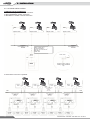
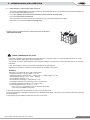
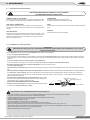
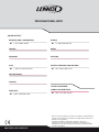
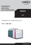
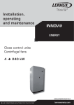
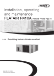
1
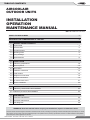
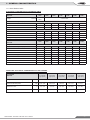
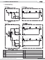
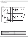
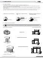
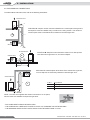
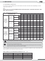
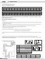
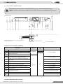
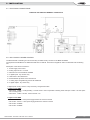
Installation, operating and maintenance AIRCOOLAIR ASC/ASH Large ducted split 19 134 kW Air cooled condensing unit 20 230 kW MIL122E-1401 06-2013 lennoxemeia.com TABLE OF CONTENTS AIRCOOLAIR OUTDOOR UNITS INSTALLATION OPERATION MAINTENANCE MANUAL Ref : MIL122E-1401 / 06-2013 POINTS TO BEAR IN MIND 2 DATA PAGE FOR COMMISSIONING OF THE UNIT 3 1 - GENERAL CHARACTERISTICS 1.1 Physical data 4 1.2 Electrical data 5 1.3 Fan performance 6 1.4 Operating limits 6 1.5 Piping drawings 7 1.6 Unit dimensions 11 2 - INSTALLATION 2.1 Preliminary preparations 12 2.2 Unit acceptance 12 2.3 Unit location 13 2.4 Installation clearances 13 2.5 Inside location 14 2.6 Refrigerant connections 15 2.7 Electrical connections 19 2.8 Dry contact board control 21 2.9 Options installation 22 3 - COMMISSIONING AND OPERATION 3.1 Preliminary checks before first installation 23 3.2 Preliminary checks at first installation 24 4 - MAINTENANCE 4.1 Preventive maintenance 25 4.2 Corrective maintenance 25 4.3 Fault diagnosis 26 WARNING: Read this manual before carrying out installation, repair or maintenance work. All the technical and technological information contained in this manual, including any drawings and technical descriptions provided by us, remain the property of Lennox and must not be utilised (except in the operation of this product), reproduced, issued to or made available to third parties without the prior written agreement of Lennox. AIRCOOLAIR - ASC/ASH - MIL122E-1401 / 06-2013 •1• POINTS TO BEAR IN MIND DANGER AND WARNING SIGNS Abrasive surfaces Low temperatures High temperatures Risk of injury from moving objects Electrical voltage Risk of injury from rotating objects ELECTRICAL CONNECTIONS Make sure to switch off the power before installing, repairing or carrying out maintenance on the unit, in order to prevent serious electrical injury. Keep local and national legislation in mind when installing the unit. Standard Guidelines to Lennox equipment All technical data contained in these operating instructions, including the diagrams and technical description remains the property of Lennox and may not be used (except for the purpose of familiarizing the user with the equipment), reproduced, photocopied, transferred or transmitted to third parties without prior written authorization from Lennox. The data published in the operating instructions is based on the latest information available. We reserve the right to make modifications without notice. We reserve the right to modify our products without notice without obligation to modify previously supplied goods. These operating instructions contain useful and important information for the smooth operation and maintenance of your equipment. The instructions also include guidelines on how to avoid accidents and serious damage before commissioning the equipment and during its operation and how to ensure smooth and fault-free operation. Read the operating instructions carefully before starting the equipment, familiarize yourself with the equipment and handling of the installation and carefully follow the instructions. It is very important to be properly trained in handling the equipment. These operating instructions must be kept in a safe place near the equipment. Like most equipment, the unit requires regular maintenance. This section concerns maintenance and management personnel. If you have any queries or would like to receive further information on any aspect relating to your equipment, do not hesitate to contact us. •2• AIRCOOLAIR - ASC/ASH - MIL122E-1401 / 06-2013 DATA PAGE FOR UNIT COMMISSIONING UNIT: ___________________________________________ SERIAL NUMBER : ___________________________________ CONTROL PANEL IDENTIFICATION CODE : _________________________________________________________________ INSTALLATION ADDRESS: _______________________________________________________________________________ INSTALLER : _____________________________________ INSTALLER TEL : ____________________________________ INSTALLER ADDRESS : __________________________________________________________________________________ ______________________________________________________________________________________________________ COMMISSIONING DATE : ________________________________________________________________________________ CHECKS : _____________________________________________________________________________________________ ______________________________________________________________________________________________________ SUPPLY VOLTAGE : _______________________________ RATED VOLTAGE OF THE UNIT : _______________________ YES NO Unit on shock absorbers Drainage with trap Main power supply connection Control panel connection Compressor oil level indicator DATA INPUT: COOLING CYCLE HEATING CYCLE Air intake temperature to the outdoor coil: 1 ºC 2 ºC Air output temperature to the outdoor coil: 1 ºC 2 ºC High pressure: Low pressure: Circuit 1 Circuit 2 Circuit 1 Circuit 2 Air intake temperature to the outdoor coil: 1 ºC 2 ºC Air output temperature to the outdoor coil: 1 ºC 2 ºC High pressure: Low pressure: Circuit 1 Circuit 2 Circuit 1 Circuit 2 ELECTRIC POWER CONSUMPTION (Amps) Compressor 1: . . . . . . . . . . . . . . . . . . . Compressor 1: . . . . . . . . . . . . . . . . . Compressor 2 : . . . . . . . . . . . . . . . . . . Compressor 2 : . . . . . . . . . . . . . . . . Compressor 3 : . . . . . . . . . . . . . . . . . . Compressor 3 : . . . . . . . . . . . . . . . . Outdoor fan section 1 . . . . . . . . . . . . . Outdoor fan section 1 . . . . . . . . . . . Outdoor fan section 2 . . . . . . . . . . . . . Outdoor fan section 2 . . . . . . . . . . . Options installed : ____________________________________________________________________________ ___________________________________________________________________________________________ ___________________________________________________________________________________________ Comments : _________________________________________________________________________________ ___________________________________________________________________________________________ ___________________________________________________________________________________________ AIRCOOLAIR - ASC/ASH - MIL122E-1401 / 06-2013 •3• 1.- GENERAL CHARACTERISTICS 1.1.- PHYSICAL DATA A S Unit AIRCOOLAIR C 020 S M S: One Circuit D: Two Circuits C: Cooling only H: Heat pump S: Outdoor unit Split N 3 M: 400V/3/50 Type of refrigerant M: R-410A --- Approximate cooling capacity in kW M Number of revision ASC/ADC: Cooling only unit R-410A. ASH/ADH: Heat pump unit R-410A. MODELS ASC/ASH 020S 025S Type of compressor 1 Cooling only unit ASC/ADC Heat pump unit ASH/ADH kg 255 443 452 520 258 452 463 537 3 6 6 6 11000 9750+9750 11500+11500 11000+11000 Optional Soft starter Optional FP1 N/A m3/h Air flow 035S Scroll Number of compressors Net weight 030S Refrigerant charge NITROGEN (*) n/a: not available MODELS ASC/ASH 040S 045D 1 2 255 070D 085D 2 2 2 443 452 481 520 258 452 463 499 537 3 6 6 6 6 11000 9750+9750 11500+11500 11300+11300 11000+11000 Type of compressor Scroll Number of compressors Cooling only unit ASC/ADC Net weight Heat pump unit ASH/ADH kg Optional Soft starter Optional FP1 N/A m3/h Air flow 055D Refrigerant charge NITROGEN (*) n/a: not available MODELS ASC/ASH 100D 120D Type of compressor Cooling only unit ASC/ADC Heat pump unit ASH/ADH Optional Soft starter Optional FP1 Air flow Refrigerant charge 200D 230D Scroll Number of compressors Net weight 140D kg 2 2 3 3 3 632 797 906 1659 1679 748 828 932 1684 1704 9 9 9 n/a n/a 40 40 40 80 80 m3/h 22700+18100 22700+18100 22700+22700 28600+28600 36000+36000 NITROGEN (*) (*) The units are supplied with nitrogen gas; this must be removed and the unit charged with refrigerant R-410A, depending on unit model. (See page 21 to calculate refrigerant charge for model ASC/ADC and ASH/ADH units to work with indoor units CIC/CIH). R-410A factory refrigerant precharge kit is available as an option. •4• AIRCOOLAIR - ASC/ASH - MIL122E-1401 / 06-2013 1.- GENERAL CHARACTERISTICS 1.2.- ELECTRICAL DATA ELECTRICAL CONSUMPTION FOR STANDARD UNITS MODELS ASC/ASH Voltage 020S 025S 030S 3N~400V 50Hz Ph/V/Hz 035S 040S 045D 055D 3~400V 50Hz Maximum absorbed power (kW) Compressor 8,25 10,1 11,8 15,6 16,9 20,2 23,6 Fan 0,3 0,69 0,69 0,84 0,84 1,38 1,38 Total power 8,55 10,79 12,49 16,44 17,74 21,58 24,98 15 21 22 25,6 31 42 44 Maximum current (A) Compressor Fan 1,6 3 3,4 3,4 3,4 6 6,8 Total current 16,6 24 25,4 29 34,4 48 50,8 Start up current (A) 87,5 97,4 104 138 17,2 121 129 MODELS ASC/ASH 070D 085D 100D 120D 140D 200D 230D Voltage Ph/V/Hz 3~400V 50Hz Maximum absorbed power (kW) Compressor 31,1 33,8 42,6 45,6 55,9 78,8 88,2 Fan 1,68 1,68 3,05 3,05 4 4,2 8 Total power 32,78 35,48 45,65 48,65 59,9 83 96,2 Compressor 51,2 62 77,6 84 102 142 159 Fan 6,8 6,8 6,4 6,4 8 9,6 16 Total current 58 68,8 84 90,4 110 151,6 175 Start up current (A) 167 206 221 228 292 302,9 358 Maximum current (A) ADDITIONAL ELECTRICAL CONSUMPTION FOR THE OPTIONS FP1 OPTION ASC/ASH Voltage 100D FP1 120D FP1 140D FP1 200D FP1 230D FP1 (Low Speed/ High speed) (Low Speed/ High speed) (Low Speed/ High speed) (Low Speed/ High speed) (Low Speed/ High speed) Ph/V/Hz Maximum absorbed power kW 3/400V/50Hz 2,00 / 6,20 2,00 / 6,20 1,00 / 5,2 5,8 / 14,2 2 / 10,4 Maximum current A 3,2 / 9,8 3,2 / 9,8 1,6 / 8,2 9,6 / 22,8 3,2 / 16,4 Start up current A 3,2 / 9,8 3,2 / 9,8 1,6 / 8,2 9,6 / 22,8 3,2 / 16,4 AIRCOOLAIR - ASC/ASH - MIL122E-1401 / 06-2013 •5• 1.- GENERAL CHARACTERISTICS 1.3.- FAN PERFORMANCES 1.3.1.- OUTDOOR UNIT WITH AVAILABLE HIGH PRESSURE FAN (OPTION) Air flow data / FP1 option / Low speed. MODELS 100D - 120D - 140D Fan type 230D Airflow rate Airflow rate 100 Absorbed power Airflow rate Airflow rate 2 4 m /h 19000 + 19000 28000 + 28000 kW 5 10 m3/h 18000 + 18000 24000 + 24000 10.2 3 Absorbed power 125 75 50 Fan number Available static pressure (Pa) 200D Axial “short case” - direct coupling 900 r.p.m. (Low speed) 3~400V Absorbed power Absorbed power kW 5,1 m3/h 17000 + 17000 22000 + 22000 kW 5,2 10,4 N/A m3/h 15000 + 15000 20000 + 20000 N/A kW 5,3 10,6 N/A N/A n/a: Not available Air flow data. FP1 option. High speed. MODELS 100D - 120D - 140D Axial “short case”-direct coupling 1450 r.p.m. (High speed) 3~400V Fan type Airflow rate 100 Absorbed power Airflow rate 125 50 Fan number Available static pressure Pa, 200D - 230D Airflow rate Absorbed power Absorbed power 2 4 m3/h 22000 + 22000 34000 + 34000 kW 9,2 18,4 m3/h 20000 + 20000 28000 + 28000 kW 9,3 18,6 m3/h 18000 + 18000 24000 + 24000 kW 9,4 18,8 1.4.- OPERATING LIMITS COOLING ONLY UNITS Indoor temperature Cooling cycle operation Outdoor temperature HEAT PUMP UNITS Maximum temperatures Minimum temperatures 32ºC DB 23ºC WB 45ºC (20S-25S-30S-45D-55D) ------------47ºC (35S-40S-70D-85D-100D-120D-140D) 21ºC DB 15ºC WB Outdoor temperature Minimum temperatures 32ºC DB 23ºC WB 21ºC DB 15ºC WB 20S-25S-30S-45D-55D) ------------47ºC (35S-40S-70D-85D-100D-120D-140D) 0ºC 27ºC DB 15ºC DB Depending on model (See tables for heating capacities) -10ºC DB -11ºC WB Indoor temperature Heating cycle operation Outdoor temperature (*) With low temperature 0ºC kit (option) DB: Dry bulb temperature. (**) With option kit low temperature -15ºC or kit -15ºC and low noise level. WB: Wet bulb temperature •6• (*) / (**) Maximum temperatures Indoor temperature Cooling cycle operation +10ºC STANDARD UNIT AIRCOOLAIR - ASC/ASH - MIL122E-1401 / 06-2013 1.- GENERAL CHARACTERISTICS 1.5.- PIPING DRAWINGS COOLING ONLY UNITS Service valve option INDOOR UNIDAD UNIT INTERIOR CIC 020S/025S/030S/035S/040S DS OUTDOOR UNIT UNIDAD EXTERIOR ASC 020S/025S/030S/035S/040S Fan motor LPT1 LP1 Scroll compressor HP1 HPT1 PT1 Coil Coil Fan 1 CH Suction accumulator (long distance connection option). C1 SVL1 Expansion valve Filter drier Service valve option (ELEMENTO OPCIONAL) OPTION ELEMENT OUTDOOR UNIT UNIDAD EXTERIOR UNIDAD INTERIOR CIC 045D/055D/070D/085D INDOOR UNIT Service valve option ASC 045D/055D/070D/085D Fan motor LPT1 LP1 Scroll compressor HP1 PT1 HPT1 1 CH C1 Fan Coil Suction accumulator (long distance connection option). DS Coil SVL1 Expansion valve Filter drier Service valve option 055D/070D/085D Service valve option OS Fan motor LP2 LPT2 Scroll compressor HP2 PT2 HPT2 3 CH C2 Suction accumulator ( long distance connection option). Coil SVL3 Expansion valve Filter drier Service valve option OPTION ELEMENT (ELEMENTO OPCIONAL) DS Pressure gauge. (5/16” to be fitted by the installer) HP1 High pressure switch, circuit 1. Discharge sensor HP2 High pressure switch, circuit 2. CH1 Crankcase heater (Low ambient option) SVL3 To be connected by the installer to indoor units. CH3 Crankcase heater (Low ambient option) LPT1 Low pressure switch, circuit 1 HPT1 High pressure transducer, circuit 1 LPT2 Low pressure transducer, circuit 2 HPT2 High pressure transducer, circuit 2 SVL1 Liquid solenoid valve. (long distance option) OS AIRCOOLAIR - ASC/ASH - MIL122E-1401 / 06-2013 Outdoor temperature sensor •7• 1.- GENERAL CHARACTERISTICS 1.5.- PIPING DRAWINGS COOLING ONLY UNITS OUTDOOR UNIT INDOOR UNIDAD UNIT INTERIOR UNIDAD EXTERIOR ASC 100D/120D/140D Service valve option CIC 100D/120D/140D Fan Fan motor Scroll compressor HP1 LPT1 LP1 HPT1 PT1 1 CH Coil DS 2 CH C1 Coil Scroll compressor Suction accumulator (Low ambient -15ºC and low noise level option). SVL1 Filter drier Service valve option Service valve option Expansion valve DS LPT2 LP2 Scroll compressor HP2 HPT2 PT2 Fan motor Coil 3 CH C2 Coil Suction accumulator (Low ambient -15ºC and low noise level option). SVL3 Expansion valve Filter drier Service valve option (ELEMENTO OPCIONAL) OPTION ELEMENT DS Pressure gauge. (5/16” to be fitted by the installer) HP1 High pressure switch, circuit 1. Discharge sensor HP2 High pressure switch, circuit 2. CH... Crankcase heater (Low ambient option) SVL1 Liquid solenoid valve. (long distance option) SVL3 To be connected by the installer to indoor units. HPT1 High pressure transducer, circuit 1 LPT1 Low pressure switch, circuit 1 HPT2 High pressure transducer, circuit 2 LPT2 Low pressure transducer, circuit 2 OS •8• Outdoor temperature sensor AIRCOOLAIR - ASC/ASH - MIL122E-1401 / 06-2013 1.- GENERAL CHARACTERISTICS 1.5.- PIPING DRAWINGS HEAT PUMP UNITS UNIDADUNIT INTERIOR INDOOR OUTDOOR UNIT UNIDAD EXTERIOR ASH 020S/025S/030S/035S/040S Service valve option CIH 020S/025S/030S/035S/040S DS Fan Coil LPT1 LP1 Scroll compressor Fan motor 4-way valve HP1 HPT1 PT1 1 CH Expansion valve Filter drier Check valve Service valve option C1 SVL1 Coil Suction accumulator (Remote connection option) OS SVL2 Check valve Suction accumulator Filter drier Expansion valve Check valve Check valve (ELEMENTO OPCIONAL) OPTION ELEMENT UNIDAD UNIT INTERIOR INDOOR UNIDAD OUTDOOREXTERIOR UNIT ASH 045/055D/070D/085D Service valve option CIH 045/055D/070D/085D Fan motor Scroll compressor LP1 LPT1 4-way valve HP1 HPT1 PT1 1 CH Coil C1 Coil DS Expansion valve Filter drier Check valve Suction accumulator (Long distance connection option) Service valve option Fan Suction accumulator SVL1 SVL2 Check valve Filter drier Check valve Expansion valve Check valve Service valve option 64D/76D/86D Fan motor LP2 LPT2 HP2 Expansion valve Check valve 4-way valve HPT2 PT2 3 CH C2 Filter drier OS Scroll compressor Coil Suction accumulator (Long distance connection option) Service valve option SVL3 SVL4 Check valve Filter drier Check valve Expansion valve Suction accumulator Check valve (ELEMENTO OPCIONAL) OPTION ELEMENT DS Pressure gauge (5/16” to be fitted by the installer) HP1 High pressure switch, circuit 1. Discharge sensor HP2 High pressure switch, circuit 2. CH... Crankcase heater SVL1 Liquid solenoid valve (long distance option) SVL3 To be connected by the installer to indoor units. SVL2 Liquid solenoid valve (long distance option) SVL4 LPT1 Low pressure switch, circuit 1 LPT2 Low pressure transducer, circuit 2 AIRCOOLAIR - ASC/ASH - MIL122E-1401 / 06-2013 HPT1 High pressure transducer, circuit 1 HPT2 High pressure transducer, circuit 2 OS Outdoor temperature sensor •9• 1.- GENERAL CHARACTERISTICS 1.5.- PIPING DRAWINGS HEAT PUMP UNITS OUTDOOR UNIT UNIDAD EXTERIOR ASH 100D/120D/140D Service valve option INDOOR UNIT UNIDAD INTERIOR CIH 100D/120D/140D DS Fan Fan motor Scroll compressor LPT1 LP1 4-way valve HPT1 PT1 1 CH Coil Coil 2 CH C1 Service valve option Expansion valve Filter drier Check valve SVL1 Suction accumulator Filter drier SVL2 Check valve Suction accumulator (Long distance connection option) Scroll compressor Check valve Expansion valve Check valve Service valve option OS DS Coil Fan motor LPT2 LP2 Scroll compressor 4-way valve HPT2 PT2 3 CH Coil 112D/128D C2 Liquid receiver Check valve SVL3 Suction accumulator (Long distance connection option) Service valve option Fan Suction accumulator SVL4 Filter drier Expansion valve Expansion valve Filter drier Check valve Check valve Check valve Check valve OPTION ELEMENT DS Pressure gauge (5/16” to be fitted by the installer) HP1 High pressure switch, circuit 1. Discharge sensor HP2 High pressure switch, circuit 2. CH... Crankcase heater SVL1 Liquid solenoid valve. (long distance option) SVL3 To be connected by the installer to indoor units. SVL2 Liquid solenoid valve. (long distance option) SVL4 LPT1 Low pressure switch, circuit 1 LPT2 Low pressure transducer, circuit 2 • 10 • HPT1 High pressure transducer, circuit 1 HPT2 High pressure transducer, circuit 2 OS Outdoor temperature sensor AIRCOOLAIR - ASC/ASH - MIL122E-1401 / 06-2013 1.- GENERAL CHARACTERISTICS 1.6.- DIMENSIONS OF ASC/ASH/ADC/ADH UNIT 020S 025S/030S/035S/040S Main switch (option) Main switch (optional) Electrical box 1375 1635 119 5 660 Power supply cable entry Access to gas and liquid lines Access to gas and liquid lines 1195 045D/055D/070D/085D 980Electrical box 100D/120D/140D Electrical box Main switch (optional) 1635 2128 Electrical box Main switch (optional) 196 0 Access to gas and liquid lines 1195 Access to gas and liquid lines 225 0 1420 Power supply Power supply 200D-230D 2227 Main switch (optional) Electrical box Access to gas and liquid lines 225 0 Power supply AIRCOOLAIR - ASC/ASH - MIL122E-1401 / 06-2013 0 230 Access to gas and liquid lines • 11 • 2.- INSTALLATION 2.1.- PRELIMINARY PREPATATIONS All INSTALLATION, SERVICE and MAINTENANCE work must be carried out by QUALIFIED PERSONNEL. The unit must be transported in a VERTICAL POSITION on its metal mounting frame. Any other position may cause serious damage to the machine. When the unit is received, it should be checked to assure that it has received no shocks or other damage, following the instructions on the packaging. If there is damage, the unit may be rejected by notifying the LENNOX Distribution Department and stating why the machine is unacceptable on the transport agent’s delivery note. Any later complaint or claim made to the LENNOX Distribution Department for this type of damage cannot be considered under the Guarantee. Sufficient space must be allowed to facilitate installation of the unit. The unit may be mounted outdoors. When the unit is mounted on the floor, ensure that the position is not subject to flooding. When positioning the unit, be sure that the Rating Plate is always visible since this data will be necessary to ensure correct maintenance. The units are designed to be installed with ducts designed by qualified technical staff. The joints to be used between ducts and openings in the unit should be Elastic Joints. Avoid the use of BYPASS joints between the extraction air and input air. The structure where the unit is placed must be able to support the weight of the unit during operation. 2.2.- UNIT RECEPTION How to hoist the unit Use separators Use separators WITH BALANCE BEAM WITH HOOK NOTE: Use slingers of 6 m with the hook in order to prevent pressure on the top of the unit because it can be damaged.Whenever it is possible, use balance beam. Hook Crane Crane Sling 6 m Balance beam Sling Hooker • 12 • AIRCOOLAIR - ASC/ASH - MIL122E-1401 / 06-2013 2.- INSTALLATION 2.3.- UNIT LOCATION - The bedplate is made up of metal sections, capable of withstanding the weight of the unit. - If the unit is floor mounted, then the profiles should be isolated with shock absorbing material such as anti-vibration units or pads. Bear in mind that the fans rotate at approximately 850 rpm. - The unit is able to work in normal radio interference conditions for commercial and residential installations. For any other conditions please consult us. - If the outside temperature in the area where the heat pump unit is to be installed is low or the operating cycle is too long, it may be necessary to install an electrical heater in the drip tray, to prevent the formation of ice in the coil during the defrost cycle. 1. Mounting on a low sensitivity area. 2. Mounting on a medium sensitivity area. Unit Unit Damping spring 3.Mounting on a high sensitivity area (Check floor loading). Unit Metal and concrete structure Metal and concrete structure Support Support Rubber mounting Damping spring Rubber mounting Rubber mounting 2.4.- INSTALLATION CLEARANCES FAILURE TO INSTALL THE UNITS AS SHOWN WILL IMPACT PERFORMANCE AND RELIABILITY. INSTALLATION CLEARANCES DETAILING AVM POSITIONS 1195 1145 1m (*) 130 400 ASC/ASH 020S 1m 1m (*) 660 3m (*) O14 1m (*) 1m (*) 25 ASC/ASH 025S/030S/035S/040S 3m 1195 1m 1m O14 90 1m 800 980 1145 1m 25 1960 ASC/ASH 045D/055D/070D/085D 1m 955 O14 90 800 955 1195 3m 1m 1m 25 (*) Clearance around the unit. AIRCOOLAIR - ASC/ASH - MIL122E-1401 / 06-2013 Size in mm. • 13 • 2.- INSTALLATION INSTALLATION CLEARANCES DETAILING AVM POSITIONS 2250 ASC/ASH 100D/120D/140D 965 682 1420 682 965 14 28 160 675 700 675 100 784 696 2300 752 ASC/ASH 200D/230D 14 34 675 700 675 2250 (*) Clearance around the unit. Size in mm. 2.5.- INDOOR LOCATION Air outlet Air outlet duct (2) Unit Air inlet Auxiliary drip tray (heat pump unit) Air inlet duct (1) In heat pump units with double circuits and cooling units 100D-140D only, if only one duct is going to be installed, a regulated pressure damper should be installed for each fan, to avoid air by-pass through the fan if it has stopped. For inside location, keep the following advice in mind: - During the heat pump defrost cycle, the units produce a large quantity of melted water. If you wish to drain this water, adequate drainage should be installed below the unit to collect and lead the water to the desired location. - Air duct installation: If an air duct has been installed, the operating limits will be reduced (see operating limits section in this manual). (1) The air intake plenum (option) available for models 100D-140D facilitates the installation of the air intake duct. (2) The discharge plenum (option) permits the installation of a square discharge duct with options FP1. • 14 • AIRCOOLAIR - ASC/ASH - MIL122E-1401 / 06-2013 2.- INSTALLATION 2.6- REFRIGERANT CONNECTIONS The unit is supplied with the gas and liquid lines sealed with copper caps outside the casing with possibility to install pipe lines (unless the unit is supplied with the factory precharged refrigerant kit (option) or service valves kit (option). Copper cap Refrigerant pipe lines Brazing Standard units are filled with Nitrogen gas, which must be removed before any operation on the unit. As an option, the unit can be supplied with service valves on the gas and liquid lines, with Nitrogen charge (N2) or refrigerant charge (R-410A). FOR STANDARD UNITS AND UNITS SUPPLIED WITH SERVICE VALVES PROCEED AS FOLLOW: 1. Remove the nitrogen gas through the high and low 5/16” service ports located inside and provide a low vacuum for safety. 2. Remove the caps from the connecting lines. 3. Braze the piping connection lines. Select piping diameter from TABLE 1. (When brazing refrigerant pipes, nitrogen gas must be supplied into the pipes through the service ports to remove the air). 4. Leak test: Add nitrogen gas, check that a pressure of 5 kg/cm2 has been reached and that there are no leaks in the circuit or brazing by applying soapy water to the pipes which will cause the bubbles to form where there are leaks. To detect small leaks, proceed as follows: Add nitrogen gas and check that a pressure of 25 kg/cm2 has been reached, there are no leaks if the pressure remains the same for at least 24 hours and the final pressure is not less than 10% below the initial pressure. 5. Ensure that the gas line is insulated. 6. Evacuation: Remove the nitrogen gas, connect the gauge manifold and vacuum pump to both the liquid and gas lines, fully open the gauge manifold valve and switch on the vacuum pump. Check to make sure the gauge shows a pressure of -750mm Hg. Once a level of -750mm Hg is reached, keep the vacuum pump running for at least one hour. 7. Refrigerant charge: - Check TABLE 3.1. and 3.2. for the amount of refrigerant charge, depending on the length and size of the pipe connections. - Disconnect the vacuum pump and connect to the refrigerant-charging bottle. Open the charging pump and purge the air from the hose at the pressure gauge manifold. - Set up the amount of additional refrigerant on the weighing scale, open the high pressure and charged in the liquid state. If the total amount of refrigerant charge has not been reached because the pressure is balanced, turn off the high side of the gauge manifold, turn on the unit, and add the remaining amount of the refrigerant charge required slowly through the low side of the pressure gauge. (With R-410A refrigerant, the charging bottle must be in a vertical position and charged in the liquid state). Close the pressure gauge, disconnect it from the from the service port of the unit and fit caps on the service ports. The unit is then ready to operate. During installation, keep the gas and liquid pipes covered, in order to prevent humidity and dirt from entering them. Take special care that the refrigerant pipes are insulated. Avoid collapse on lines installation. FOR UNITS SUPPLIED WITH SERVICE VALVES AND FACTORY PRECHARGED REFRIGERANT KIT, PROCEED AS FOLLOWS: 1. Release the refrigerant pressure from the connecting line through the service port located in that line. 2. Remove the caps from the connecting lines. Service port Service valve 3. Braze the interconnection line to the indoor unit. 4. With the service ports closed, evacuate and connect the vacuum pump to the To the indoor To outdoor unit 5/16” service port on the connecting line to achieve a pressure of -750 mm unit piping Hg; after that, keep the vacuum pump running for at least one hour in order to Copper cap provide a vacuum to the connecting lines and the indoor unit. Disconnect the Copper tube to connect to vacuum pump. indoor unit 5. Refrigerant charge: Remove vacuum pump and connect the refrigerant bottle. Check TABLE 2 for refrigerant charge per meter of copper pipe for the corresponding model. Adjust the amount of refrigerant on the weighting scale and open the pressure gauge to charge in liquid state (with R-410A refrigerant, the charging bottle must be in a vertical position and it is important to charge in the liquid state). Close the pressure gauge, disconnect it from the service port of the unit and fit the caps. 6. Open the service valves. 7. The unit is ready to operate. AIRCOOLAIR - ASC/ASH - MIL122E-1401 / 06-2013 • 15 • 2.- INSTALLATION 2.6- REFRIGERANT CONNECTIONS To locate outdoor and indoor units, refer to the following information: OUTDOOR UNIT 2% POSITION A: A siphon suction must be installed in the vertical part of the gas line, and siphons must be installed every 8 meters in the rising section. The minimum suction speed must not be below 6m/s. Maximum vertical length 16m. 2 L 1 A INDOOR UNIT 2% OUTDOOR UNIT B INDOOR UNIT POSITION B: Slope the lines toward the outdoor unit. Take special care with lines longer than 10, and avoid collapse. 2% 1 2 L POSITION C: Install a siphon at the base of the vertical of the gas line, no more siphons are necessary. Maximum vertical length 16 m. 2% OUTDOOR UNIT INDOOR UNIT L 2 1 C A, B, C : Unit positions L: Total length 1= Gas line 2= Liquid line 2% NOTE: The units are supplied with welded connections. As an option, service valves are available for liquid and gas lines. - GAS LINES MUST ALWAYS BE INSULATED. - THE HORIZONTAL LINES MUST SLOPE AT LEAST 2% TOWARDS THE OUTDOOR UNIT. - THE MAXIMUM SPEED IN THE LINES, SHOULD NOT BE MORE THAN 15 m/sec. • 16 • AIRCOOLAIR - ASC/ASH - MIL122E-1401 / 06-2013 2.- INSTALLATION 2.6- REFRIGERANT CONNECTIONS For units with 2 circuits, please be sure to connect indoor unit circuits C1 and C2 to the corresponding C1 and C2 circuits of the outdoor unit. Note : MODELS 100D and 120D USE DIFFERENT SIZES OF PIPE CONNECTIONS : LARGE SIZE FOR CIRCUIT 1 AND SMALL SIZE FOR CIRCUIT 2. TABLE 1: REFRIGERANT LINES SELECTION Sizes REFRIGERANT LINES C1 Ø Liquid Total line length. (Length refrigerant lines between indoor unit and outdoor unit.) 0 to 30 m. (Standard connection of unit) Ø Gas 30 to 65 m. Total line length. (Length refrigerant lines between indoor unit and outdoor unit.) 0 to 30 m. (Standard connection of unit) Ø Gas 30 to 65 m. Max. nr of bends 045D 055D 5/8” 5/8” 5/8” n/a n/a n/a n/a 5/8” 5/8” 1 1/8” 1 1/8” 1 3/8” 1 3/8” 1 1/8” 1 1/8” C2 n/a n/a n/a n/a n/a 1 1/8” 1 1/8” 6 12 8 18 12 12 8 5/8” 5/8” 5/8” 3/4” 3/4” 5/8” 5/8” C2 n/a n/a n/a n/a n/a 5/8” 5/8” C1 1 1/8” 1 1/8” 1 3/8” 1 3/8” 1 5/8” 1 1/8” 1 3/8” C2 n/a n/a n/a n/a n/a 1 1/8” 1 3/8” 12 18 18 18 18 18 18 070D 085D 100D 120D 140D 200D 230D C1 5/8” 5/8” 3/4” 3/4” 3/4” 7/8” 7/8” C2 5/8” 5/8” 5/8” 5/8” 3/4” 7/8” 7/8” C1 1 3/8” 1 3/8” 1 5/8” 1 5/8” 1 5/8” 1 5/8” 2 1/8” C2 1 3/8” 1 3/8” 1 3/8” 1 3/8” 1 5/8” 1 5/8” 2 1/8” 18 12 12 12 12 12 12 3/4” 3/4” 7/8” 7/8” 7/8” n/a n/a C1 Ø Gas 040S 5/8” n/a Max. nr of bends Ø Liquid 035S 5/8” 7/8” Max. nr of bends Ø Liquid 030S 5/8” C1 C1 Ø Gas 025S 1/2” C2 Max. nr of bends Ø Liquid 020S C2 3/4” 3/4” 3/4” 3/4” 7/8” n/a n/a C1 1 3/8” 1 5/8” 1 5/8” 1 5/8” 1 5/8” n/a n/a C2 1 3/8” 1 5/8” 1 5/8” 1 5/8” 1 5/8” n/a n/a 18 18 12 12 12 n/a n/a n/a: not available With lines length between 40 and 65 m, long distance option must be selected. Units are factory pre-charged with Nitrogen (N2). The installer should remove the nitrogen and charge the units with the R-410A refrigerant shown in the following tables and also the charge per meter of line shown in TABLE 2. The unit is supplied as standard with brazed connections. A factory pre-charged kit is available as an option. If fitted, TABLE 2 is the only one to take into account (this option includes service valves). TABLE 2: WEIGHT OF R-410A REFRIGERANT PER METER OF LINE LIQUID GAS 1/2” 5/8” 5/8” 3/4” 3/4” 7/8” 7/8” 1-1/8” 1-3/8” 1-3/8” 1-5/8” 1-5/8” AIRCOOLAIR - ASC/ASH - MIL122E-1401 / 06-2013 g/m 108 177 182 265 271 374 • 17 • 2.- INSTALLATION 2.6- REFRIGERANT CONNECTIONS TABLE 3.1 : REFRIGERANT CHARGE Charge of refrigerant (gr) R-410A for 0 meters of line ASC + indoor unit (Cooling only) C1 C2 020S 025S 030S 035S 040S 045D 055D 070D 085D 100D 120D 140D 200D 230D 5155 ------ 5315 ------ 5700 ------ 7950 ------ 9745 ------ 6250 6250 5775 5775 7870 7870 9800 9800 12130 10450 15585 10045 15500 15400 23100 23100 24250 24250 140D 17230 17100 200D 25660 25660 230D 26950 26950 Charge of refrigerant (gr) R-410A for 0 meters of line ASH + indoor unit (Heat pump) C1 C2 020S 5725 ------ 025S 5900 ------ 030S 6330 ------ 035S 8835 ------ 040S 10830 ------ 045D 6940 6940 055D 6420 6420 070D 8740 8740 085D 10900 10900 100D 13480 11600 120D 17315 11160 Note : MODELS 100D and 120D USE DIFFERENT SIZES OF PIPE CONNECTIONS : LARGE SIZE FOR CIRCUIT 1 AND SMALL SIZE FOR CIRCUIT 2. REFRIGERANT CHARGE FOR THE SET: EXAMPLE: To install a ASH 030S + CIH 030S set, with 22 m refrigerant line length between the outdoor and indoor units, the refrigerant charge must be calculated as follows: 1 TABLE 1 (p. 20) shows that for 22m of line length between the indoor unit and outdoor units, the line sizes are: liquid 5/8” and gas 1 1/8”. 2 TABLE 2 (p. 20) shows, for line sizes of 5/8”-1 1/8”, the charge per meter of line is: 177 g/m x 22m = 3894 g. 3 TABLE 3.1 shows charge of refrigerant for a set with 0m line length is: 6330 g. 4 To determine the charge of the set: Add the charge in the refrigerant lines + the charge in the indoor unit and outdoor refrigerant units. Total charge for the set: 3894 + 6330 = 10224 g Note: If the outdoor unit includes the factory pre-charged kit, only the weight of refrigerant per meter of line in TABLE 2 is taken into account. 100D to 140D units with 3 compressors are working using three capacity steps and 200D-230D with 4 capacity steps. See the picture below for the installation in the case of units with tandem compressor circuit. An additional gas line has to be used to assure the correct operation of the system. Condensing unit with capacity reduction 2 3 Tandem compressor circuit 4 H4 Min 0.25% gradient H1 15 m max H2 5 m max H4 0,15 m min 4 H4 Coupled trap 3 Lower trap with double tubes 4 Higher trap with double tubes H1 Indoor unit 2 H2 3 • 18 • 2 Models with tandem compressor 100D 120D 140D 200D 230D Circuit 1 Circuit 1 Circuit 1 Circuits 1 & 2 Circuits 1 & 2 AIRCOOLAIR - ASC/ASH - MIL122E-1401 / 06-2013 2.- INSTALLATION 2.7.- ELECTRICAL CONNECTIONS - BEFORE MAKING ANY ELECTRICAL CONNECTIONS, ENSURE THAT ALL CIRCUIT BREAKERS ARE OPEN. - IN ORDER TO MAKE THE ELECTRICAL CONNECTIONS, FOLLOW THE ELECTRICAL DIAGRAM SUPPLIED WITH THE UNIT. DS AS DADS AS HR/T CO2 INDOOR SECTION RS HR/T BAC RS LDRP DPT DIFS 5 6 4 2 3 1 Electrical box AS OS OS HR/T Note: The length of all cables for connection with indoor unit must be less than 65 m. PT1 PT2 OUTDOOR SECTION To connect by installer CONNECTION OF CONTROL ELEMENTS: COMPONENT DS Discharge sensor OS Outdoor sensor AS Remote ambient sensor RS Remote duct sensor Split unit Condensing unit N/A STANDARD STANDARD 2 x 1 mm² (shielded) RS HR/T Duct remote sensor for enthalpic free-cooling 5 x 1 mm² (shielded) CO2 CO2 Air quality probe. (Available only with enthalpic free-cooling) 4 x 1 mm² (shielded) DPT Air differential pressure transducer 3 x 1 mm² (shielded) OS HR/T Outdoor sensor for enthalpic free-cooling N/A 5 x 1 mm² (shielded) OPTION AS HRT Remote ambient sensor for enthalpic free-cooling 5 x 1 mm² (shielded) DIFS Dirty filter sensor LDRP Long distance connection DADS Smoke detector 7 x 1,5 mm² BAC Hot water coil 5 x 1,5 mm² 2 x 1,5 mm² 3 x 1,5 mm² (units 1 circuit) 2 x (3 x 1,5 mm²) (units 2 circuits) VOLTAGE OPERATING LIMITS: 342-462V AIRCOOLAIR - ASC/ASH - MIL122E-1401 / 06-2013 • 19 • 2.- INSTALLATION 2.7.- ELECTRICAL CONNECTIONS POWER SUPPLY Power supply 020S 025S 030S Power supply Power supply with electrical heater Fan Free-cooling Exhaust fan Return fan 1 1’ 2 4 5 6 5 x 4 mm² 5 x 10 mm² 4 x 1,5 mm² 7 x 1,5 mm² 3 x 1,5 mm² N/A 5 x 6 mm² 5 x 16 mm² 4 x 1,5 mm² 7 x 1,5 mm² 3 x 1,5 mm² N/A 4 x 1,5 mm² 7 x 1,5 mm² 3 x 1,5 mm² N/A 4 x 1,5 mm² 7 x 1,5 mm² 3 x 1,5 mm² N/A 3 x 25 mm² + 2 x 16 mm² 3 x 25 mm² + 2 x 16 mm² 3 x 35 mm² + 2 x 16 mm² 3 x 50 mm² + 2 x 25 mm² 4 x 1,5 mm² 7 x 1,5 mm² 3 x 1,5 mm² N/A 4 x 1,5 mm² (STD/HP1) 4 x 2,5 mm² (HP2/HP3) 7 x 1,5 mm² 4 x 1,5 mm² 4 x 1,5 mm² 3 x 25 mm² + 2 x 16 mm² 3 x 70 mm² + 2 x 35 mm² 4 x 1,5 mm² (STD/HP1) 4 x 2,5 mm² (HP2/HP3) 7 x 1,5 mm² 4 x 1,5 mm² 4 x 1,5 mm² 3 x 35 mm² + 2 x 16 mm² 3 x 35 mm² + 2 x 16 mm² 3 x 50 mm² + 2 x 25 mm² 3 x 70 mm² + 2 x 25 mm² 3 x 95 mm² + 2 x 25 mm² 3 x 95 mm² + 2 x 50 mm² 3 x 95 mm² + 2 x 50 mm² 3 x 95 mm²+ 2 x 50 mm² 4 x 2,5 mm² (STD/HP1) 2 x (4 x 1,5 mm²) (HP2/HP3) 4 x 2,5 mm² (STD/HP1) 2 x (4 x 2,5 mm²) (HP2/HP3) 4 x 2,5 mm² (STD/HP1) 2 x (4 x 2,5 mm²) (HP2/HP3) 7 x 1,5 mm² 4 x 1,5 mm² 4 x 2,5 mm² 7 x 1,5 mm² 4 x 1,5 mm² 4 x 2,5 mm² 7 x 1,5 mm² 4 x 1,5 mm² 4 x 2,5 mm² N/A N/A N/A N/A N/A N/A N/A N/A N/A N/A 035S 5 x 6 mm² 040S 5 x 10 mm² 045S 5 x 16 mm² 055D 5 x 16mm² 070D 085D 100D 120D 140D 200D 230D n/a: not available Power supply Electrical heater (3) Standard Medium High Modulating 4 x 2,5 mm² + 6 x 1,5 mm² 4 x 2,5 mm² + 6 x 1,5 mm² 4 x 2,5 mm² + 6 x 1,5 mm² 4 x 4 mm² + 6 x 1,5 mm² 4 x 4 mm² + 6 x 1,5 mm² 4 x 4 mm² + 6 x 1,5 mm² 4 x 6 mm² + 6 x 1,5 mm² 4 x 6 mm² + 6 x 1,5 mm² 4 x 6 mm² + 6 x 1,5 mm² 4 x 10 mm² + 6 x 1,5 mm² 4 x 10 mm² + 6 x 1,5 mm² 4 x 10 mm² + 6 x 1,5 mm² 4 x 4 mm² + 6 x 1,5 mm² 4 x 4 mm² + 6 x 1,5 mm² 4 x 4 mm² + 6 x 1,5 mm² 4 x 6 mm² + 6 x 1,5 mm² 4 x 6 mm² + 6 x 1,5 mm² 4 x 6 mm² + 6 x 1,5 mm² 3 x 10 mm²+PE + 6 x 1,5 mm² 3 x 10 mm²+PE + 6 x 1,5 mm² 3 x 10 mm²+PE + 6 x 1,5 mm² 4 x 16 mm² + 6 x 1,5 mm² 4 x 16 mm² + 6 x 1,5 mm² 4 x 16 mm² + 6 x 1,5 mm² 4 x 6 mm² + 6 x 1,5 mm² 4 x 6 mm² + 6 x 1,5 mm² 4 x 6 mm² + 6 x 1,5 mm² 4 x 10 mm² + 6 x 1,5 mm² 4 x 10 mm² + 6 x 1,5 mm² 4 x 10 mm² + 6 x 1,5 mm² 4 x 16 mm² + 6 x 1,5 mm² 4 x 16 mm² + 6 x 1,5 mm² 4 x 16 mm² + 6 x 1,5 mm² 4 x 25 mm² + 6 x 1,5 mm² 4 x 25 mm² + 6 x 1,5 mm² 4 x 25 mm² + 6 x 1,5 mm² 4 x 6 mm² + 7 x 1,5 mm² 4 x 6 mm² + 7 x 1,5 mm² 4 x 6 mm² + 7 x 1,5 mm² 4 x 10 mm² + 7 x 1,5 mm² 4 x 10 mm² + 7 x 1,5 mm² 4 x 10 mm² + 7 x 1,5 mm² 4 x 16 mm² + 7 x 1,5 mm² 4 x 16 mm² + 7 x 1,5 mm² 4 x 16 mm² + 7 x 1,5 mm² 4 x 25 mm² + 7 x 1,5 mm² 4 x 25 mm² + 7 x 1,5 mm² 4 x 25 mm² + 7 x 1,5 mm² 200D N/A N/A N/A N/A 230D N/A N/A N/A N/A 020S 025S 030S 035S 040S 045S 055D 070D 085D 100D 120D 140D n/a: not available • 20 • AIRCOOLAIR - ASC/ASH - MIL122E-1401 / 06-2013 2.- INSTALLATION 2.7.- ELECTRICAL CONNECTIONS COMFORT AND SERVICE TERMINAL CONNECTION 2.8.- DRY CONTACT BOARD CONTROL The AIRCOOLAIR condensing unit can be remotely controlled via dry contacts on the BM60 and BE60. The expansion board BE60 is an additional board fixed on DIN rail. This board is supplied in stand on AIRCOOLAIR condensing unit. Description of the various connectors : 1 Power supply of the board 2 Analog output 0/10V : not used 3 Network bus to the CLIMATIC 60 BM60 4 4 digital inputs : dry contacts only 5 LED status of the network bus 6 Serial address dip-switch of the network bus 7 4 analog input configurable by pair B1-B2 and B3-B4 8 4 digital outputs : dry contact only 6 digital inputs are dry contacts. They are factory configured as follow : 2 inputs on the BM60 • BM-J4-ID4 : TCB B = Cooling/Heating - Contact closed = the unit operates in heating mode and open contact = the unit operates in cooling mode • BM-J4-ID7 : TCB G = On/Off - Contact closed = On. 4 inputs on the BE60 • BE-J4-ID1 : TCB Y1 = 50% power engaged when the contact is closed • BE-J4-ID2 : TCB Y2 = 100% power engaged when the contact is closed • BE-J4-ID3 : Available • BE-J4-ID4 : Available AIRCOOLAIR - ASC/ASH - MIL122E-1401 / 06-2013 • 21 • 2.- INSTALLATION 2.9 - OPTIONS INSTALLATION COMMUNICATION CAPABILITIES 1. BMS MODBUS_RS485 or TCP/IP connection. 2. BMS LONWORKS_Echelon connection. 3. BMS BACnet - RS485 or TCP/IP connection. BM60 BM60 SERIAL CARD BM60 SERIAL CARD CH1 MODBUS LON WORKS FTT 10A BACNET CH2 BM60 SERIAL CARD SERIAL CARD CH3 CH4 MODBUS LON WORKS FTT 10A BACNET Cable c. section (mm2) two wire S12E racing from min. 0.2 a max. 2.5 mm2 AWG 20/22 1000m. max. RS485 SERIAL CARD BM60 RS232 230V BMS Connect a 120 1/4 W terminating resistor, MODBUS only. A master-slave connection is possible : SERIAL BM60 CARD J11 J10 J11 J10 Cable c. section (mm²) 3 shielded pairs AWG24 500 m max. A Cable c. section (mm²) 3 shielded pairs AWG24 500 m max. C DT50 A B • 22 • RT2 J11 J10 RT3 J11 Cable c. section (mm²) 3 shielded pairs AWG24 500 m max. LAN DC60 SERIAL BM60 CARD SERIAL BM60 CARD SERIAL BM60 CARD RT1 DS60 A B DC60 DS60 Cable c. section (mm²) 3 shielded pairs AWG24 500 m max. C DT50 A DS60 C DT50 B B DC60 RT12 LAN Cable c. section (mm²) 3 shielded pairs AWG24 500 m max. C DT50 J10 DC60 DS60 AIRCOOLAIR - ASC/ASH - MIL122E-1401 / 06-2013 3.- COMMISSIONING AND OPERATION 3.1.- PRELIMINARY CHECKS BEFORE STARTUP - Check that the power supply is the same as stated on the Rating Plate which is in agreement with the electrical diagram for the unit and that cable sizes are correct. - Check that tightness of the electrical connections to their terminals and to ground. - Check the control panel connections. (If the connection is incorrect, the unit will not operate and the control panel display will not light). - Check with your hand that the fans are turning freely. FIGURE FOR THE STANDARD UNIT CONFIGURATION FOR MODELS: 045D-055D-070D-085D •• • •• mode set on of f CHECK COMPRESSOR OIL LEVEL - Part of the compressor oil is pumped to the system when the compressor starts, so for split systems part of the oil can be placed in the system: piping lines, traps, evaporator, etc. - The quantity of oil in the system depends on the refrigerant charge. The compressor cannot work with incorrect or excessive refrigerant. - It may be necessary to add oil to the system, depending on the piping length. - See below an example of calculation of the oil quantity to be added to the system. EXAMPLE: ASH 030S + CIH 030S with 65 m. (with remote option). - Refrigerant charge = 6.33 kg (TABLE 3.1, p. 21). - Refrigerant charge to add with 65 m = 182g/m x 65 = 11.83kg. (TABLE 2, p. 20). - Total refrigerant charge = 6.33 + 11.83 = 18.16 kg. - Oil compressor charge (l) = 3.25 - Oil compressor charge (kg) = 2.925 (density = 0.9). - Permissible quantity in the system (kg) = 0.03 (= 2.925 x 0.01). - Permissible refrigerant charge (kg) = 6 (= 0.03/ 0.005). - Excess refrigerant charge = 18.16 - 6 = 12.16 60.8 g (= 12.16 x 5 g) quantity of oil to be added to the system. 0.55 l of oil to be added to the system. In the event of having to add oil, remember the type of oil is synthetic POE. The original oil charge, including the compressor, is ICI Emkarate RL32-3MAF. This type of oil must also be used when replacing the oil completely. If only topping up, RL32-3MAF or Mobil EAC Artic 22C can be used. AIRCOOLAIR - ASC/ASH - MIL122E-1401 / 06-2013 • 23 • 3.- COMMISSIONING AND OPERATION 3.2.- PRELIMINARY CHECKS AT STARTUP To start the unit, follow the instructions given in the User Manual for the control supplied with the unit (requiring operation in any of the modes, cooling, heating, or automatic). After a time delay, the unit will start. With the unit operating, check that the fans are turning freely and in the correct direction. CHECK THAT THE COMPRESSOR IS ROTATING IN THE CORRECT DIRECTION - If you have the option phase rotation indicator, use it to check the correct rotation. - If you do not have three phase return lock, check the correct direction of rotation. The suction pressure decreases and the discharge pressure increases when the compressor is started. - If the connection is incorrect, rotation will be reversed, causing a high noise level and a reduction in the amount of current consumed. If this occurs, the compressor’s internal protection system will operate to shut down the unit. The solution is to disconnect, reverse two of the phases and connect again. ASTP Protection is included with the unit compressors. See "Fault diagnosis" for more information. WITH OPERATING UNIT, CHECK: - Low pressure and high pressure. - Use the evaporating and liquid temperature to calculate superheat and subcooling. - Adjust the refrigerant charge and/or expansion valve according to the preceding values. COMPRESSOR OIL LEVEL The oil level must always be checked. When the compressor is at rest, the level should be between 1/4 and 3/4 in the sight glass, while when running the level should be between 3/4 and full. In the event of having to add oil, remember the type of oil is synthetic POE. The original oil charge in the compressor is ICI Emkarate RL32-3MAF. This type of oil must also be used when replacing the oil completely. When only topping up, RL32-3MAF or Mobil EAC Artic 22C can be used. The unit must be installed in accordance with local safety codes andregulations and can only be used in a well ventilated area. Please readcarefully the manufacturer’s instructions before starting this unit All work on the unit must be carried out by a qualified and authorised employee. Non-compliance with the following instructions may result in injury or serious accidents. Work on the unit: The unit shall be isolated from the electrical supply by disconnection and locking using the main isolating switch. Workers shall wear the appropriate personal protective equipment (helmet, gloves, glasses,etc.). Electrical system: Electrical connections can become loose during transport. Please check them before starting-up the unit Compressors with specific rotation direction. Check the correct rotation direction of the fan before closing the compressor circuit breakers. If the direction is incorrect, the phases must be reversed at the head of the main switch. Work on electric components shall be performed with the power off (see below) by employees having valid electrical qualification and authorisation. Refrigerating circuit(s): After more than 12 hours of power cut, the cranckcase heater (compressor) should be powered for 5 hours before any return to service. Non-compliance with this instruction can cause deterioration of the compressors. Monitoring of the pressures, draining and filling of the system under pressure shall be carried out using connections provided for this purpose and suitable equipment. • 24 • To prevent the risk of explosion due to spraying of coolant and oil, the relevant circuit shall be drained and at zero pressure before any disassembly or unbrazing of the refrigerating parts takes place. There is a residual risk of pressure build-up by degassing the oil or by heating the exchangers after the circuit has been drained. Zero pressure shall be maintained by venting the drain connection to the atmosphere on the low pressure side. The brazing shall be carried out by a qualified brazier. The brazing shall comply according to code ASME section IX following the procedures specific. Before starting up - Test the circuit to the maximum working pressure(see the nameplate) - Verifify the operation of the high pressure swich. - Check the piping and the components of the refrigerant circuit. Replacing components: In order to maintain CE marking compliance, replacement of components shall be carried out using spare parts, or using parts approved by Lennox. Only the coolant shown on the manufacturer’s nameplate shall be used, to the exclusion of all other products (mix of coolants, hydrocarbons, etc.). CAUTION: In the event of fire, refrigerating circuits can cause an explosion and spray coolant gas and oil. AIRCOOLAIR - ASC/ASH - MIL122E-1401 / 06-2013 4.- MAINTENANCE 4.1.- PREVENTIVE MAINTENANCE PREVENTIVE MAINTENANCE PREVENTS COSTLY REPAIRS. THIS REQUIRES PERIODIC INSPECTIONS: GENERAL STATE OF THE CASING: Furniture, paint, damage due to shocks, rust spots, levelling and supporting, condition of the shock absorbers, if installed, screwed panels, etc. COMPRESSOR: If a sight glass is fitted, check the oil level. Check the condition of the silentbloc mountings. ELECTRICAL CONNECTIONS: State of hoses, tightness of screws, earthing, current consumption of the compressor and fans and check that the unit is receiving the correct voltage. FANS: Check that fans turn freely and in the correct direction without excessive noise. COOLING CIRCUIT: Check that the pressures are correct and that there are no leaks. Check that there is no damage to the pipe insulation, that the condition of the coils is good and that they are not blocked by bits of paper or plastic drawn in by the air flow, etc. CONTROL: Check Set Points and normal operation. 4.2.- CORRECTIVE MAINTENANCE IMPORTANT MAKE SURE THAT THE UNIT IS FULLY DISCONNECTED FROM THE POWER SUPPLY WHEN CARRYING OUT ANY TYPE OF WORK ON THE MACHINE. If any component in the cooling circuit is to be replaced, follow these recommendations: - Always use original replacement parts. - If the component can be isolated, it is not necessary to remove the entire refrigerant charge, if the component cannot be isolating and the refrigerant charge is removed, it should be removed through the Schrader valves located in the outdoor section. Create a slight vacuum as a safety measure. - Regulation prohibits the release of refrigerant into the atmosphere. - If cuts must be made in the pipe work, use pipe cutters. Do not use saws or any other tools that produce filings. - All brazing must be carried out in a nitrogen atmosphere to prevent corrosion forming. - Use silver alloy brazing rod. - Take special care that the flame from the torch is directed away from the component to be welded and cover with a wet rag to prevent overheating. - Take very special care if 4-way or check valves are to be replaced since these have internal components that are very heat-sensitive such as plastic, teflon, etc. - If a compressor is to be replaced, disconnect it electrically and un-braze the suction and discharge lines. Remove the securing screws and replace the old compressor with the new one. Check that the new compressor has the correct oil charge, screw it to the base and connect the lines and electrical connections. - Evacuate above and below through the Schrader valves of the outdoor unit until -750 mm Hg is reached. Once this level of vacuum has been reached, keep the pump running for at least one hour. DO NOT USE THE COMPRESSOR AS A VACUUM PUMP. - Charge the unit with refrigerant according to the data on the Rating Plate for the unit and check that there are no leaks. Direction of the flame Silver alloy welding rod Wet rag Nitrogen Component to be welded PRECAUTIONS TO BE TAKEN WHEN USING OF R-410A Refrigerant: - R-410A refrigerant is used in the unit; the following standard precautions for this gas should therefore be taken: The Vacuum Pump must have a Check Valve or Solenoid Valve fitted. Pressure Gauges and Hoses for exclusive use with R-410A Refrigerant should be used. Charging should be carried out in the Liquid Phase. Always use scales to weigh-in charge Use the Leak Detector exclusive for R-410A Refrigerant. Do not use mineral oil, only synthetic oil to ream, expand or make connections. Keep pipes wrapped before using them and be very thorough about any possible dirt (dust, filings, burrs, etc.). When there is a leak, collect what remains of the charge, create a vacuum in the unit and completely recharge with new R-410A Refrigerant. Brazing should always be carried out in a nitrogen atmosphere. Reamers should always be well sharpened. AIRCOOLAIR - ASC/ASH - MIL122E-1401 / 06-2013 • 25 • 4.- MAINTENANCE 4.3.- FAULT DIAGNOSIS In case of failure or malfunction of the unit, the display on the control panel will show an error or alarm warning which is explained in the control panel manual. Nevertheless, whenever there is a unit fault, the unit should be shut down and our service technicians consulted. FAULT UNIT DOES NOT START POSSIBLE CAUSES POSSIBLE SOLUTIONS Fault in the power supply or insufficient voltage. Connect the power supply or check the voltage. Circuit breakers have opened. Reset. Power cable or control panel cable is defective. Inspect and correct. High pressure switch is defective. Check cut-off pressure switch or replace pressure switch if necessary. Outdoor fan is not working. Check for voltage, inspect the motor and turbine or replace if necessary.. UNIT STOPS DUE TO HIGH PRESSURE Outdoor fan turns in the wrong direction. DURING THE COOLING CYCLE Reverse the power phases. Outdoor coil is dirty or clogged for passing air. Inspect and clean. Excess refrigerant charge. Remove the charge and charge according to the data on the rating plate. UNIT STOPS DUE TO HIGH PRESSURE The same causes and solutions as the cold cycle but with reference to the coils and DURING THE HEATING CYCLE indoor fan. Low pressure switch defective. Check the cut-off pressure with a pressure gauge and replace the pressure switch if necessary. Indoor fan is not working. Check for voltage and inspect the motor, turbine and replace if necessary. Indoor fan turns in the wrong direction. Reverse the power phases. Lack of refrigerant. Leak. Correct leak, create vacuum and charge. Dirty air filter. Inspect and clean Clogged cooling circuit. Dirty filter drier. Inspect and correct or change the filter drier. Compressor overcharged. Inspect suction and discharge pressure values and correct. Compressor cuts off due to Klixon. Check input voltage and voltage drop. Lack of refrigerant. Correct leak and replace. UNIT STOPS DUE TO LOW PRESSURE UNIT STARTS AND STOPS IN SHORT CYCLES LOAD AND ABNORMAL NOISE IN THE Power supply phases inverted. COMPRESSOR (SCROLL) (three-phase compressor). • 26 • Check and reverse power phases. AIRCOOLAIR - ASC/ASH - MIL122E-1401 / 06-2013 4.- MAINTENANCE 4.3.1.- SAFETY DEVICES ASTP COMPRESSOR PROTECTION: This device protects the compressor against high discharge temperatures. When the temperature reaches critical values, ASTP protection causes the "Scrolls" to separate. The compressor stops pumping but the motor continues to run. Unit with specific compressor protection La unidad incorpora compresor con protección específica - Occasionally, when the compressor stops and starts, there is a metallic noise due to the compressor scrolls. This is normal. - Connect high and low pressure gauges and check that the operating pressures are normal. - Measure electrical consumption for the unit and check that it is close to that indicated on the specification plate. - Check the electrical consumption of the compressor and the fans against that specified in the physical data sheets. - In the case of a Heat Pump unit, make a cycle change on the Control Panel, checking that the 4-way valve makes the change correctly. Check the pressures in the new cycle. - Split and Multi-split: Low pressure switch and high pressure switch are reset automatically and if it operates 3 times in one hour, they change to manual reset, through the control unit. - With C60 control: Low pressure switch and high pressure switch are reset automatically and if it operates 3 times in one day, they change to manual reset, through the control unit. AIRCOOLAIR - ASC/ASH - MIL122E-1401 / 06-2013 • 27 • lennoxemeia.com SALES OFFICES : BELGIUM AND LUXEMBOURG + 32 3 633 3045 FRANCE +33 1 64 76 23 23 GERMANY +49 (0) 40 589 6235 0 ITALY + 39 02 495 26 200 RUSSIA +7 495 626 56 53 SPAIN +34 902 533 920 UKRAINE +380 44 461 87 79 UNITED KINGDOM AND IRELAND +44 1604 669 100 NETHERLANDS + 31 332 471 800 POLAND +48 22 58 48 610 PORTUGAL +351 229 066 050 OTHER COUNTRIES : LENNOX DISTRIBUTION +33 4 72 23 20 00 Due to Lennox’s ongoing commitment to quality, the specifications, ratings and dimensions are subject to change without notice and without incurring liability. Improper installation, adjustment, alteration, service or maintenance can cause property damage or personal injury. Installation and service must be performed by a qualified installer and servicing agency MIL122E-1401 06-2013