1
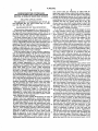
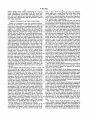
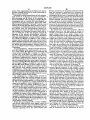
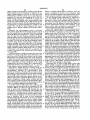
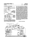
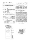
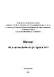
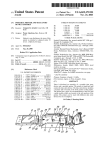
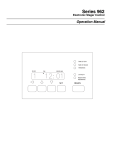
United States Patent [19]
[11]
Patent Number:
4,469,602
Seal
[45]
Date ‘of Patent:
Sep. 4, 1984
[54] MICROCOMPUTER CONTROLLED
DEMAND/SCHEDULED WATER SOFTENER
HAVING AUTOMATIC RESIN BED
SENSING
OTHER PUBLICATIONS
Operating Manual, “Compute-A-Save System”, Water
Re?ning Company, Middletown, Ohio, Jul. 1, 1978.
[75] Inventor:
J. David Seal, Waukesha, Wis.
Sales Literature, “Water King”, Sta-Rite Industries,
Dela?eld, Wisc.
Sales Literature, “The Lindsay KNOW-IT-ALL”,
[73] Assignee:
Autotrol Corporation, Milwaukee,
The Lindsay Corporation.
Wis.
Primary Examiner—1vars C. Cintins
Attorney, Agent, or Firm—-Quarles & Brady
[57]
ABSTRACT
[21] Appl. No.: 502,967
[22] Filed:
[63]
An improved control for a water softener includes a
Jun. 10, 1983
Related US. Application Data
Continuation-impart of Ser. No. 412,279, Aug. 27,
1982, Pat. N0. 4,426,294.
[51]
Int. Cl.3
[52]
US. Cl. .................................... .. 210/662; 210/85;
.....
. . . . . . . . . ..
B01J 49/00
210/89; 210/98; 210/140; 210/143; 364/502
[58]
Field of Search ............... .. 210/662, 670, 687, 89,
210/98, 102, 103, 109, 140, 143, 190, 191, 26.9,
85; 364/500, 502
[56]
References Cited
U.S. PATENT DOCUMENTS
4,237,538 12/1980 Le Dall ............................. .. 364/500
4,257,887
4,275,448
4,332,678
4,385,357
3/1981
6/ 1981
6/1982
5/1983
resin bed sensor for sensing when the resin bed has been
depleted to a predetermined percentage of the total
resin bed treating capacity. The resin bed sensor is con
nected to a microcomputer which is also coupled to a
flow meter to receive data therefrom indicative of the
quantity of treated water leaving the water treatment
device over a given period of time. When the resin bed
sensor signals the microcomputer that the resin bed has
been depleted to the predetermined capacity the mi
crocomputer calculates the total softening capacity of
the resin bed. Each day, the microcomputer computes
both the total quantity of treated water consumed since
the last regeneration and the remaining capcity of the
resin bed. The microcomputer also maintains a record
in memory of the previous 7 days‘ usage and the aver
age usage is calculated to establish a soft water reserve
value. Should the remaining resin bed capacity be less
than the established soft water reserve, the regeneration
is initiated.
'1
9 Claims, 11 Drawing Figures
U.S. Patent
Sep. 4, 1984
Sheet 1 of9
n
Z
8%
a
/
/
7.
w
(k
4,469,602
F 6.
n»%
u,uM‘
M”
0
23b
(V:
CIRCUIT 5
Fl
U.S. Patent
Sep. 4, 1984
Sheet 2 of9
4,469,602‘
2%
FIG.2
3“
25m
EA
Ztm
2.5’?
52;
US. Patent
Sep. 4, 1984
ITITTI
Sheet 4 of9
l
4,469,602
US. Patent
Sep. 4, 1984 "
Sheet 5 of9
4,469,602
TO, FROM
CKT. 50
FIG. 4
\\A
FIGAQ
‘U.S. Patent
Sep. 4, 1984.
Sheet 6 of9
4,469,602
@100
POWER
7
-
ENTER
DEFAULT
VALUES
Z02.
1.;
SET DA'LY
CHECK now
DEFLIJ®AL$EFLAG
,
Z04
A u?’
'NPUT FOR
,
TRANSITION
Zokp
205
7,30
YES
_
‘
YES
WHICH 1
swncu
Pi2
FIND
DISPLAY
24 HOUR
n
CLOCK
'
NO
INCREMENT
FLOW
1
COUNT
8
234w
74°
‘
TOGGLE
FLOW
L.ED.
‘____________l
INCREMENT\
POWER LOSS “1.5m,
COUNTER
OUTPUT
J
1,?)
7
2.3%
men’ I TO
DISPLAY
DISPLAY
ERROR
$
CODE
OUTPUT
l6
laml-iTER 19g‘: \71‘
A
w
N171
240
.
-
2
CHECK
l SEC
COUNT
YES
NO
BLANK
D'SPLA
,
‘
U.S. Patcnt
Sep . 4,
1984
Sheet 7 of 9
FIG.5B
FROM
FIG.5A
4,469,602
[22b
RELOAD
| SEC
COUNTER
INC
l0 SECOND
COUNT
- 214
V
CONVERT \
PULSES
TO GALLONS
INCRVEMENT
/-—— 2710
1 HOUR
COUNT
ADD GALLONS \
TO
DAILY TOTAL
ADD DAILY
TOTAL AND 'IOTAL/
SINCE LAST
REGERALTION
-——-L—-\CLEAR /- 2.1"! A
RES IN
CAPACITY
CALCULATE
UPDATED RESIN
CAPACI T Y
/
‘
ENTER DAILY \
USAGE DEFAULT
VALUES
‘ CLEAR DAILY
USAGE DEFAULT ~
FLAG
' SET SENSOR
FLAG
TURN IT
ON
US. Patent
Sep.4,198l4 ‘
Sheet8 0f9
MAKE
/
4,469,602
25o
SURE
IT IS OFF
F |G.5C
MAKE
SURE
'
IT IS ON
‘M8
CLEAR
secouos
REsToRE
CLEAR
DATA FOR
10 SECONDS
D|$pLAY
25A
2%)
V
T
CLEAR
MN.
a»
1
(2510
. Z55
INCREMENT
HOURS
SAVE
DATA
Zuo
$533
7.7L)
BLANK
DATA FOR
DISPLAY
FLAG
\
T
CLEAR
ERROR
CODE
2102.
~
Z95
C
U.S. Patent
Sep. 4, 1984 A
Sheet 9 of 9
FROM
FIG. 58
ADD TODAY'S
4,469,602
H6. 50
~ 2501\
GALLONS TO
TOTAL BETWEEN
REGENERATION
T
CALCULATE
/334
REMAINING
CAPACITY
‘
COMPARE
/33“’
TO RESERVE
VALUE
CALCULATE
7 DAY
a
AVERAGE
30”’
SHIFT
DATA IN
FOR AVG.
SAVE
TODAYS GAL
TO COMPARE
GAINST
RELAY W
‘
31L»
CLEAR
GALLONS
USED
1
?>?J.\
RESET
DAY it
REGERATION
SINCE START
u?
A
\
32.1.2
320
TOGGLE
LED I75
)
1
4,469,602
MICROCOMPUTER CONTROLLED
DEMAND/SCHEDULED WATER SOFI‘ENER
HAVING AUTOMATIC RESIN BED SENSING
RELATED APPLICATIONS
This application is a continuation-in-part of US. pa
tent application Ser. No. 412,279 ?led Aug. 27, 1982,
now US. Pat. No. 4,426,294.
2
ener control units, the frequency at which such de
mand-type water softener control units initiate regener
ation is dependent on the selected reserve value repre
senting the anticipated amount of soft water which will
be used prior to the next regeneration interval. Since the
actual amount of soft water used will likely not remain
constant, but will vary greatly from day to day, the
chosen reserve value must be made large to assure that
soft water will always be produced by the water soft
10 ener. Thus, regeneration will likely occur at a greater
BACKGROUND OF THE INVENTION
This invention relates generally to a control unit for a
resin bed type water softener and more particularly to
an improved microcomputer-based control unit for a
frequency than is actually necessary.
In an effort to overcome the disadvantages of prior
art water softener control units, I previously invented
the “Microcomputer Controlled Demand/Scheduled
Water Softener” described and claimed in copending
resin bed water softener which initiates regeneration of
the water softener resin bed only when necessary.
US. patent application Ser. No. 412,279 ?led Aug. 27,
1982, now US. Pat. No. 4,426,294 and assigned to the
assignee of the present invention. The water softener
described in that patent application operates to initiate
The most common type of water softener is the ion
exchange resin-type softener having a tank which holds
a bed of resin through which the hard water is passed to
remove undesirable minerals and other impurities. The
water softener‘ regeneration when a reserve value, cal
culated in accordance with the average daily soft water
capacity of the resin bed to absorb minerals and impuri
ties is ?nite and it is thus necessary to periodically re
consumption, exceeds the remaining treatment capacity
charge or ‘regenerate the resin bed with a regenerant,
of the water softener. The remaining treatment capacity
typically a brine solution so as to restore the capacity of
of the water softener resin bed is mathematically calcu-.
25
the resin- bed for further water treatment.
lated by ?rst determining the total treating capacity of ‘
With the earliest types of water softeners regenera
the water softener resin bed, in accordance with the
tion was effected manually only after it was discovered
ratio of the unit’s softening capacity (as measured in
that the treatment capacity of the resin bed has been
kilo grains) to the incoming water hardness (as measured
exceeded and the water ?owing therethrough was no
in grains/gallon). The remaining capacity is then ob
longer soft. In an effort to eliminate the need for manual
tained from the difference between the total resin bed
regeneration, water softener control systems were de
softening capacity (in gallons) and the quantity of water
veloped utilizing a mechanical clock which initiated
used since the previous regeneration.
water softener regeneration on a periodic basis, the
The calculation of the remaining water softener resin
frequency of such regeneration being set in accordance
with the known capacity of the resin bed and the antici
pated daily usage of soft water. While mechanical
35
bed capacity performed by the control of my previous
invention assumes that the hardness of the water re
clock-type water softener control units have alleviated
mains constant and that the total treating capacity of the
the need for manually regenerating the water softener
resin bed, such water softener control units are subject
to the disadvantage that by regenerating the water soft
ever, in practice the hardness of the water entering the
water softener resin bed also remains constant. How
water softener frequently varies for many reasons. Ad- -
ditionally, the treating capacity of the water softener
ener resin bed at ?xed intervals, regeneration may actu
ally be occurring too often if actual soft water consump- .
tion is less than the anticipated soft water consumption
or not often enough when the actual soft water con
sumption exceeds the anticipated soft water consump
tion. Regenerating the water softener resin bed when
suf?cient capacity still exists to treat an amount of water
equal to, or in excess of the anticipated soft water con
sumption, is wasteful of salt and the water needed in
regeneration. Conversely, failure to regenerate the
water softener resin bed after the resin bed capacity has
diminished to a point below that required to treat the
actual quantity of soft water demanded results in hard
water leaving the water softener.
In an effort to better regulate the frequency of water
45
resin bed itself may vary from the speci?ed treating
capacity because the treating capacity of the resin itself
may vary from that speci?ed by the manufacturer. Fur
thermore the amount of salt used for each regeneration
may vary because of inaccuracies in the control opera
tion. This will cause thecapacity of the resin to vary
proportionately. Also, the resin bed volume may not be
accurately known so that the calculated remaining
water softener resin bed capacity may not always equal
the actual remaining water softener resin bed capacity.
In an effort to overcome these possible de?ciencies,
the present invention concerns an improved microcom
puter-basedwater softener control unit which includes
a resin bed sensor for sensing when approximately one
softener resin bed regeneration, demand-type water
half, or any other portion, of the resin bed treating
required to re?ne the amount of water which would
This affords a much more accurate manner of determin
capacity has been depleted. Information from the resin
softener control units have been developed which sense
bed sensor indicative of a predetermined depletion of
the remaining capacity of the water softener resin bed
the total resin bed re?ning capacity is processed by the
to soften water. Most present day demand-type water
softener control units operate to initiate regeneration of 60 microcomputer together with data indicative of the
measured volume of the soft water consumed to yield a
the water softener resin bed at an off-peak time, usually
value, as measured in gallons, of the total resin bed
2:00 a.m., if the remaining capacity of the water softener
capacity that results from the previous regeneration.
resin bed, as sensed by the control, is less than that
likely be used prior to the next regeneration interval. 65 ing the actual resin bed capacity than calculating the
resin bed‘capacity using a theoretical value of the bed
While demand-type water softener control units do
capacity and a single value of the water hardness. At a
achieve better regulation of water softener resin bed
given time each day the microcomputer-based control
regeneration than do mechanical clock-type water soft
3
4,469,602
system initiates water softer regeneration if a reserve
4
cally, 7 daily values are stored, to re?ect the softened
value, calculated in accordance with the actual soft
water consumption exceeds the remaining water soft
water usage over a week. From the stored daily values
of treated water consumption the total amount of
treated water consummed since the previous regenera
ener resin bed capacity as previously determined from
the resin sensor information and the measured value of
soft water consumed.
tion is determined as well as the actual average of the
daily treated water consumption.
As the incoming water is treated by the resin bed of
BRIEF SUMMARY OF THE INVENTION
Brie?y, in accordance with the preferred embodi
ment of the invention, I have provided an improved
the softener, the treating capacity of the particle bed is
being depleted. When the particle bed treating capacity
has been depleted to a predetermined percentage, typi
cally 50% of the total treating capacity, then the resin
control for a water softener requiring periodic resin bed
regeneration comprising a ?ow meter for detecting the
quantity of softened water leaving the softener. My
bed sensor alerts the microcomputer. From information
provided by the resin bed sensor, the microcomputer
improved control also includes a particle bed sensor for
establishes the total resin bed treating capacity as a
sensing when the particle bed treating capacity of the
softener has been depleted to a predetermined percent
age (typically 50%) of the total particle bed treating
proportion of the amount of treated water consummed
capacity. A controller is coupled to the flow meter and
in accordance with ?ow data supplied therefrom, the
controller determines both the total quantity of treated
water leaving the softener since the time of the previous
regeneration and also determines the average of the
daily consumption of treated water. In accordance with
the average daily consumption of treated water, the
places the total resin bed capacity value previously
stored in the microcomputer memory during the last
operation cycle so that the microcomputer memory
since the previous regeneration. The calculated value of
the total resin bed capacity obtained in this way re
always contains a total resin bed capacity value truly
representative of the actual resin bed capacity. From
the total resin bed capacity value stored in the mi
controller establishes a treated water reserve represent 25
ing the amount of treated water likely to be used during
the interval prior to the next possible regeneration.
During each operational cycle of the control which
corresponds in duration to the scheduled period be
tween possible regenerations, the control determines
the total resin bed capacity which resulted from the
previous regeneration in accordance with information
crocomputer memory, the actual remaining resin bed
capacity can easily be calculated by subtracting from
the total resin bed capacity the amount of soft water
consumed. At a designated time each day, typically at
2:00 am. or such other off hour as is desirable, the mi
crocomputer compares the remaining resin bed treating
capacity of the water softener to the established reserve.
If the reserve is greater than the remaining resin bed
from the resin bed sensor and the ?ow meter. From the
capacity, then regeneration of the particle bed is initi
ated. Otherwise, the microcomputer only updates the
total resin bed treating capacity, the amount of soft
water consumed since the previous regeneration is sub
tracted to yield the remaining resin bed capacity. If the
remaining resin bed treating capacity is less than the
another 24 hour period before determining whether or
data received from the ?ow meter and -waits at least
not regeneration should occur.
It is an object of the present invention to provide an
established reserve, then regeneration of the resin bed is
improved microcomputer-based water softener control
initiated.
unit which utilizes a sensor for sensing the treating
In accordance with another aspect of this invention, I 40 capacity of the resin bed.
have /provided an improved method for controlling
It is yet another object of the present invention to
regeneration of the particle bed of a water treatment
provide an improved microcomputer-based water soft
device commencing with the steps of measuring the
ener control unit which initiates water softener resin
quantity of water leaving the softener over a given
bed regeneration when the remaining resin bed capac
period of time and then determining the actual daily
45 ity, as sensed by the resin bed sensor, is less than a re
average of the soft water consumed and the amount of
soft water consumed since the last regeneration in ac‘
cordance with the measured amounts of soft water
serve value calculated in accordance with the actual
soft water consumption so that regeneration of the resin
bed only occurs when necessary, thereby achieving a
leaving the softener. Thereafter, a reserve quantity of
soft water is established from the calculated daily aver
savings of regenerant and water.
Another object of the present invention is to provide
age of soft water consumption. The treating capacity of
a water softener control which dynamically maintains a
the resin bed is sensed to determine if a predetermined
value of the total resin bed capacity during each opera
tional cycle in accordance with the water hardness and
other variables that in fact affect the resin bed capacity.
In this way, greater efficiency is achieved.
Still another object of the present invention is to
provide a control that requires no input information
percentage of the total resin bed treating capacity has
been depleted and if so, then the total resin bed treating
capacity is established as a proportion of the quantity of
treated water consumed since the previous regenera
tion. The remaining resin bed capacity is then deter
mined by subtracting the quantity of water consumed
from total resin bed capacity. Periodically, usually once
other than to set the internal microcomputer clock as to
the time of day. All other information is determined
a day during a period of infrequent water use, the re 60 automatically by the microcomputer from the flow
maining resin bed treating capacity is compared to the
meter and the resin bed sensor. This simplifies installa
tion.
established treated water reserve and if the treated
water reserve is greater than the remaining resin bed
Yet another object of the invention is to provide a
treating capacity, then regeneration is effected.
water softener control which indicates the efficacy of
In the operation of my improved control, a mi 65 regeneration. Following initiation and completion of
crocomputer monitors the ?ow meter and records the
regeneration of the resin bed, the sensor may be interro
actual amount of treated water leaving the water treat
gated by the microcomputer to determine if the regen
ment device during the previous 24 hour period. Typi
eration was effective. If the sensor indicates that regen
5
4,469,602
eration was not effective because of a failure of some
part of the control or the associated control value or
because of a lack of regenerant, then the failure is indi
cated so that the user may re?ll the regenerant supply
or make the necessary repairs.
BRIEF DESCRIPTION OF THE DRAWINGS
The invention, both as to organization and method of
operation, together with further objects and advantages
6
and inlet valves, respectively, as the valves 25f and 252
each regulate the ?ow of hard water into tank 12 from
inlet 23:; and the flow of soft water up from draw pipe
16 (FIG. 1) out through tov outlet 23b, respectively.
Valve 25g serves to regulate the flow of brine from
brine tank 18 into tank 12 and is therefore referred to as
the brine valve. The valve 25d controls water flow in
the valve module through a port (not shown) in com
thereof may best be understood by reference to the
munication with inlet 23a and outlet 23b so that when
the inlet and outlet valves are closed, water may ?ow
following description taken in conjunction with the
accompanying drawings in which:
directly through the inlet and out the outlet while valve
25d is open. The remaining valves 25a, 25b and 25c
FIG. 1 is a resin bed type water softener embodying
the control of the present invention;
serve to control the How of water and brine from the
tank into a drain conduit 30 (FIG. 1).
During a regeneration cycle, each of valves 250
FIG. 2 is a side view of the control of the water 5
through 25g is actuated at an appropriate interval by a
softener illustrated in FIG. 1;
separate one of the corresponding cams 26a through 26g
FIG. 3 is a front view of the control of the water
carried on a cam shaft 28 when the cam shaft is rotated
softener illustrated in FIG. 1;
to bring the corresponding cam into contact with the
FIG. 3A is a cross sectional view of the resin bed
valve. Cam shaft 28 is journaled at its rearend into a cam
sensor for sensing the remaining resin bed treating ca
shaft support 31 extending upwardly from the valve
pacity, as shown in its expanded resin state;
module. The forward (rightward) end of cam shaft 28
FIG. 3B is a cross sectional view of the particle bed
sensor of FIG. 3A shown in its concentrated resin state;
FIG. 4 is an electrical schematic diagram of the cir
has forwardly extending shank for engaging the “T”
shaped slot in the rearward end of the outwardly ex
cuitry embodied in the control of the water softener 25 tending shaft 32a of a gear 32 (FIG. 3). As best illus
trated in FIG. 3, gear 32 is journaled for rotation within
illustrated in FIG. 1;
‘
the cavity 33 of a control housing 34. Returning to FIG.
FIG. 4a is a cut away view of the water softener of
2, control housing 34 is slidably secured to the forward
FIG. 1 taken along lines 4a-4a; and
end of the valve module 24 by a pair of support guides
FIGS. 5A through 5D illustrate, in ?ow chart form,
36 (FIGS. 1 and 2) which each engage complimentary
the program executed by the water softener control of
?anges (not shown) on the exterior of the control hous
the present invention during operation.
8
DETAILED DESCRIPTION OF THE
PREFERRED EMBODIMENT
Referring now to the Figures, FIG. 1 illustrates a
resin bed-type water softener 10 which includes a tank
12 containing a resin bed 14. As incoming hard water
enters the tank through an opening (not shown) in the
' top thereof, the water in the tank is forced through the
resin bed and out the draw pipe 16 extending through
the center of the resin bed so that water exiting via the
draw pipe has been treated by the resin bed to remove
mg.
a
What has been described thus far with respect to the
construction and operation of the valve module 24 is
well known in the art.
The cavity 33 (FIG. 3) within the forward end of the
control housing 34 is closed by a cover 38 which is
secured to the forward end of the control housing by
screws 39 (illustrated in FIG. 3). Referring now to FIG.
40 3 which is a frontal view of control housing 34 showing ‘
portion of cover 38 cut away, cover 38 is generally
opaque except for a window 40 which carries the indi
cia “PM” “WATER FLOW” and “NO REGEN”. As
minerals and other impurities. The capacity of resin bed
will become clear hereinafter by reference to FIG. 4,
14 to absorb the minerals and impurities of the incoming
hard water is ?nite, and depends on the treating capac 45 window 40 allows displays within the cavity to display
certain information as well as to illuminate the indicia
ity of the resin in the tank as measured in kilograins of
hardness as well as the hardness of the incoming water
on the window. Immediately below window 40 is a
passageway 41 through the cover which has a spring
as typically measured in grains per gallon. To regener
biased button 42 protruding outwardly therethrough.
ate the resin bed, once its treating capacity has been
depleted, the resin bed is flushed with a sodium chloride 50 As will also become clear by reference to FIG. 4, but
ton 42 is depressed to set the time displayed by the
brine solution so that the minerals and other impurities
can be released from the resin bed and carried out of the
tank. In practice, the brine solution is stored in a sepa
rate tank 18 and is admitted to the softener tank 12
during regeneration through a tube 20 and a air check
valve 22.
The control of brine ?ow into tank 12 from brine tank
display through window 40.
With a portion of cover 38 broken away in FIG. 3, it
can be observed that not only is gear 32 journaled
within the cavity 33, but an idler gear 44 is also jour
naled within cavity 33 and is in meshing engagement
with gear 32. Idler gear 44 is driven by a gear 46 which
is carried on the forward end of the shaft of motor 48,
(FIG. 2); the motor being mounted on the rear of the
18 as well as the control of hard water ?owing into the
tank via inlet 23a and the flow of soft water leaving the
tank via outlet 23b is accomplished by a valve module 60 control housing so that its shaft extends through the
control housing 34 and into the cavity to receive gear
24 threaded on the top of tank 12 so as to be in commu
46.
nication with the tank inlet (not shown) and draw pipe
Motor 48 of FIG. 2, which is typically a 1 RPM A.C.
16. Valve module 24 typically comprises a control body
clock motor, is energized with alternating current by a
such as manufactured by Autotrol Corporation, Glen
dale, Wis., under part No. 24N. As best illustrated in 65 control circuit 50 of FIG. 4 (described hereinafter)
when the'control circuit determines, in accordance with
FIG. 2 valve module 24 includes seven disc-type valves
25a through 25g, respectively. In the present valve
module, valves 25e and 25f are designated as the outlet
a particular algorithm, that regeneration should be ef
fected. Motor 48, when energized from control circuit
‘7
4,469,602
50, drives cam shaft 28 through gears 46, 44 and 32 to
8
phragm 49g against spring 49h. Arm 49a is thus urged to
cause cams 260 through 26g to actuate a corresponding
its upward~most position. While arm 492 remains at its
one of valves 25a through 25f respectively. The cams
26a-26f are shaped such that valves 250 through 25f
upward-most position, the head 491' of the arm 49e bears
respectively, are actuated in a particular sequence for a
leaf switch non-conductive. Although not shown,
particular duration during a single revolution of the
cam shaft so that the backwash, brining, slow rinse, and
means taking the form of a gasket or the like, is pro
vided to seal the housing 49b within the interior of the
brine re?ll & purge steps, which are normally required
to complete resin bed regeneration, are performed in
housing 49a so that the water entering openings 49d
only enters the interior of housing 49b in communica
the desired sequence. Following a single revolution of
the cam shaft, the valves return to the service position
so as to allow normal water ?ow through the softener.
tion with the openings but does not enter the remaining
portion of the interior of housing 49b. In this way,
As will be described in greater detail hereinafter, the
control circuit 50 operates to effect regeneration of the
resin bed 14 of FIG. 1, when a soft water reserve value,
against the leaf arm 49k of a leaf switch 491 to render the
switch 491 remains unexposed to the water within the
resin bed.
Referring now to FIG. 3B, if the water passing
through openings 49d in the outer housing 490 and
representing the amount of soft water likely to be used
entering inner housing 49b is hard, then the special resin
prior to the next possible regeneration interval, exceeds
the remaining treating or re?ning capacity of the resin
49c shrinks in volume so that the diaphragm 49g is no
bed. In my previous water softener control, described in
spring 49h. The amount of shrinkage shown in FIG. 3B
has been exaggerated for purposes of illustration. With
the volume of the special resin now reduced, spring 49h
co-pending patent application Ser. No. 412,279, the
remaining re?ning capacity of the resin bed was calcu
lated in accordance with the difference between the
longer urged by the volume of special resin 49c against
urges the diaphragm downwardly so as to displace arm
49e to its lower-most position. With arm 49e at its low~
er-most position, the leaf arm 49j of the leaf switch 491
the ratio of resin bed capacity measured in kilograins of
hardness to the incoming water hardness, in grains/gal 25 is no longer contacted by the head 49i of the arm so that
switch 49 now becomes conductive. In practice, with
lon) and the amount of the soft water consumed since
the resin sensor 49 located approximately half way into
the previous regeneration. The operation of my previ
the resin bed 14 within tank 12 of FIG. 1 switch 49]
ous water softener control thus assumes that the incom
total re?ning capacity of the resin bed (established by
ing water hardness and the resin bed capacity remain
constant. However, in practice, neither the incoming
becomes conductive when the resin bed capacity has
been depleted to approximately one-half (50%) of its
water hardness, nor the water softener resin bed capac
original treating capacity.
ity are constant. Thus, the required amount of regener
It should be understood that the particular embodi
ment of sensor 49 described above is only exemplary
ant and water may vary because of inaccuracies of con
trol operation.
and that other types of resin bed sensors could be uti
To overcome this disadvantage, the water softener
control of the present invention includes a resin bed
lized. For example, a resin bed sensor responsive to the
water conductivity, such as disclosed in US. Pat. No.
4,257,887, could be utilized in place of resin bed sensor
down into the bed 14 as illustrated in FIG. 1 for provid
49. Moreover, in certain instances, it may be desirable to
locate resin bed sensor 49 outside of the resin tank and
ing an electrical indication when the re?ning capacity
of resin bed 14 of FIG. 1 has been depleted to a prede 40 to feed water through the special resin 490 by way of
sensor 49, typically located approximately half way
termined percentage (typically 50%) of the total resin
bed re?ning capacity. A better understanding of the
connecting tubes (not shown).
Although water softener resin bed regeneration is
normally effected when control circuit 50 energizes
resin bed sensor 49 may be gained by reference to
motor 48, there may be instances when manual regener
FIGS. 3A and 3B which are cross sectional views of the
resin bed sensor in its expanded and contracted state, 45 ation is desired, To enable manual regeneration, gear 32
has a hub 52 extending forwardly of the gear and
respectively.
through an opening 54 (FIG. 1) in cover 38. Gear 32
Referring now to both FIGS. 3A and 3B, the resin
and hub 52 are spring biased from shaft 32a so that
bed sensor 49 comprises an outer housing 491: which is
when the hub 52 of the gear is pushed inwardly, gear 32
typically made from a water and brine impervious mate
becomes disengaged from idler gear 44 so as to allow
rial such as plastic or the like. Within housing 49a is an
the cam shaft to be manually rotated upon rotation of
interior housing 49b which contains a quantity of spe
the hub. As the hub is rotated either manually, or upon
cial resin 490 whose volume varies in accordance with
the gear 32 being driven by the motor 48, an arrow 55
the softness of the water exposed to it. Openings 49d are
on the hub points to indicia (not shown) on the face of
provided through the outer wall of the outer housing
cover 38 representing the various states of water soft
49a and openings 49d’ are provided in the outer wall of
ener operation, to indicate which step of the regenera
the inner housing 4% to allow the water within the tank
tion cycle is then being executed, or, whether valves are
12 of FIG. 1 to be exposed to the special resin 49c held
within housing 4%.
presently in the service position.
Extending vertically downwardly through the top
Protruding outwardly from the gear 32 is a member
wall of housing 49b into the interior of the inner housing 60 56 which, as the gear rotates, comes into contact with
is an arm 49e whose lower end is mounted by way of a
the spring biased arm 57a of a leaf switch 57. Leaf
switch 57 is connected to control circuit 50 in a manner
screw_ 49f to a diaphragm 49g. A spring 49h is inter
posed between the top wall of the inner housing 4% and
described hereinafter. The switch is actuated either by
the diaphragm 49g to yieldably urge the diaphragm 49g
member 56 as the gear is rotated or when the hub is
against the volume of special resin 490. As best illus 65 simply depressed since the outward force of the mem
ber 56 keeps the spring biased arm 57a from normally
trated in FIG. 3A, while the water passing through
moving downwardly to actuate the switch. When
openings 49d in outer housing 49b is soft, the volume of
switch 57 is actuated, the control circuit initiates regen
I special resin 49c is fully expanded so as to bias the dia
9
‘4,469,602
10
eration. Thus, regeneration can be effected not only by
XTALl and XTAL2. In the present preferred embodi
manually rotating hub 52 but by simply depressing the
ment, this reactance is established by a inductance 66
hub to activate switch 57.
The details of control circuit 50 are set forth schemat
ically in FIG. 4. At the heart of control circuit 50 is a
coupled across the XTALl and XTAL2 pins of mi
crocomputer 58 and a pair of ‘capacitances 68a and 68b
data processing unit 58 which, in the presently pre
ferred embodiment, takes the form of a single chip mi
puter XTALl and XTAL2 pins and the power supply
crocomputer such as a model 8048 microcomputer as
is also coupled to the microcomputer pin EA to assure
that during microcomputer operation, all memory ac
each coupled between a separate one of the microcom
common terminal. The power supply common terminal
manufactured by Intel Corporation, Santa Clara, Calif.
Microcomputer 58 includes “on-boar ” random access 10 cesses by the internal arithmetic logic unit. in response
memory for storing data previously entered to the mi
crocomputer or developed during the course of opera
tion thereof. Also, the microcomputer includes on
board read only memory in which is stored the operat
ing program to be described in greater detail with re
spect to FIGS. 5A to 5D. This program controls the
to periodic timing signals from the internal master oscil
operation of the internal microcomputer arithmetic
logic unit which performs the necessary calculations
and logic determinations, to decide whether regenera
supply voltage. Since the a.c. supply voltage is accu
lator are made from the internal random access and read
only memories of the microcomputer.
The internal timer of the microcomputer, which as
indicated serves as a real time clock, is strobed or
clocked in accordance with the alternations of the a.c.
rately maintained either at 50 or 60 Hz depending on the
custom, the frequency of alternations of the a.c. supply
tion should be effected. In addition to the on-board 20 voltage can be used as a basis of measuring real time. To
memory and the arithmetic logic unit, microcomputer
58 also includes an internal timer which serves as a real
time clock. For a further, more complete description of
the Model 8048 microcomputer, reference should be
had to the “MCS-48 User’s Manual” published by Intel
25
strobe the internal microcomputer timer, a clocking
circuit 70 is provided for supplying microcomputer at
its T1 pin with a logic level voltage which changes
logic states in accordance with the alternations of the
a.c. supply voltage. Clocking circuit 70 includes a diode
71 and a resistance 72 serially coupled between the one
of the two secondary winding terminals of transformer
60 and the base of a ?rst transistor 73 whose collector
to-emitter portion is coupled in series with a resistance
whose primary winding 60a is coupled to a supply of 30 74 between the +5 V and common terminals of power
supply 59. Transistor 73 is also coupled at its base to the
110-220 volt, 50~60 Hertz a.c. supply (not shown).
+5 V terminal of the power supply through a pair of
Because of the lack of space within the cavity 33 for the
serially coupled resistances 75a and 75b. Each time the
transformer, transformer 60 is mounted .to the rear of
a.c. voltage at the secondary 60b of transformer 60
the control housing as shown in FIG. 2. The low volt
age a.c. produced across the center tapped transformer 35 undergoes an alternation, the transistor 73 is rendered
‘ Corporation.
A 5 volt regulated dc voltage to energize microcom
puter 58 is supplied to the microcomputer at its >Vcc pin
by a power supply 59 comprised of a transformer 60
secondary winding 60b when theprimary is coupled to
conductive. A ?lter comprised of the parallel combina
the a.c. supply voltage, is rectified by a pair of diodes
tion of a capacitance 76 and a resistance 77 ?lters. stray
noise to prevent false conduction of transistor 73.
A second transistor 78 has its base coupled to the
61a and 61b whose anodes are each coupled to one of
' opposite ends of the transformer secondary winding
60b. With the diode cathodes connected together, an 40 junction between resistance 74 and transistor 73 and -
unregulated dc. voltage appears between the junction
transistor 78 has its collector-to-emitter portion coupled
between the junction resistances 75a and 75b and the
power supply common terminal. The conduction of
supply unregulated voltage (unreg) output terminal and
transistor is controlled by transistor 73 and when tran
the transformer center tap, hereinafter referred to as the
45 sistor 73 is conductive, transistor 73 shunts current from
power supply common (com) terminal.
I
the base of transistor 78 to keep transistor 78 from .con
The unregulated d.c. voltage, present between the
ducting. While transistor 73 is nonconductive, transistor
unregulated voltage and common terminals of power
78 is supplied with base current and becomes conduc
supply is ?ltered by a pair of parallel coupled capacitors
tive. In this way transistor 78 acts as a logic inverter so
62a and 62b before being supplied to a voltage regulator
63. The 5 volt regulated dc. voltage produced at the 50 that the logic level voltage appearing across transistor
78, which is supplied to the microcomputer at pin T1 to
output of the regulator, which is designated as the “+5
strobe the internal timer, will be logically inverse to the
V” output of the‘power supply, is ?ltered by a pair of
of the diode cathodes, hereafter referred to as the power
logic level voltage appearing across the collector-to~
capacitances64a and 64b coupled in parallel between
emitter portion of transistor 73.
the +5 V power supply terminal and the power supply
common terminal before being supplied to pin Vcc of 55 In order for the internal microcomputer timer to keep
the correct time, the timer must usually be initially set to
the microcomputer. Although the regulated 5 volt dc.
the appropriate time. Setting of the timer is accom
voltage produced by the power supply is well ?ltered, it
plished by closing a switch 79 coupled between the
is desirable to connect a ?lter capacitance 65 between
microcomputer timing input at pin To and the power
microcomputer pin Vcc and the power supply common
terminal. A completed circuit between the power sup 60 supply common terminal input to force the voltage at
the timing input to a logic low voltage level. In practice
ply and the microcomputer 58 is accomplished by con
switch 79 is activated by depressing button 42 (FIG. 3)
necting the microcomputer ground pin Vss to the
protruding through the cover 38 (FIG. 3). While switch
power supply common terminal.
79 is open, the timing input is maintained at a high logic
Within the microcomputer 58 is a master oscillator
(not shown) whose periodic clock signals control the 65 level voltage via a resistance 80 coupled between the
pin To and the +5 V power supply terminal.
internal microcomputer timer and arithmetic logic unit.
Because the internal microcomputer timer counts
The frequency of this oscillator is determined from the
time in accordance with the alternations of the a.c.
reactance appearing across the microcomputer pins
11
4,469,602
supply voltage as processed by clocking circuit 70, the
ductive, transistor 106 becomes conductive once the
microcomputer must be alerted as to whether the a.c.
power is reapplied to provide a low impedance path
between the microcomputer reset input and the power
supply common terminal to reset the microcomputer.
supply voltage frequency is 60 Hz. as is the case in the
United States or 50 Hz. as is the case in many European
countries. To alert the microcomputer as to the a.c.
supply voltage frequency, a switch 81 is coupled be
As will become better understood by reference to
flow chart FIGS. 5A-5D, microcomputer 58 is pro
tween the second highest order microcomputer data
bus line (7) which terminates at pin DB7 and the power
supply common terminal. After determining whether or
tion when the reamining resin bed treating capacity, as
not that bus is at a ground potential (i.e. whether or not
previous regeneration and the water hardness, is less
grammed to initiate water softener resin bed regenera
determined from the amount of water used since the
switch 79 is closed) the microcomputer then knows
than a reserve value circulated as a percentage of the
whether the a.c. supply voltage is 50 or 60 Hz., respec
actual average daily soft water consumption.
Input data representing the flow of softened water
tively.
Normally, the microcomputer power is provided
from power supply 59, and the timing signal for clock
ing the internal timer is provided from the clocking
circuit 70. However, should the a.c. supply voltage fail,
leaving resin tank 12 of FIG. 1 is supplied from a ?ow
15
meter 110 (FIG. 1) disposed in the outlet 23b to the
highest order line (17) of the ?rst of the two ports of
microcomputer 58 terminating at pin P17. Referring
then not only does the clocking circuit fail to supply
periodic pulses, but more importantly the internal mi
now to FIG. 4a, which is a cut away view of the inlet
23b taken along lines 4a-4a of FIG. 1, ?owmeter 110 is
crocomputer memories which store collected data may 20 comprised of a turbine 111 having a magnet 112a em
be erased. To keep at least the microcomputer memo
ries from being erased, a battery 82 is coupled at its
positive terminal via Zener diode 84 to the standby
voltage input pin VDD of the microcomputer 58. The
negative terminal of the battery is coupled to the power
supply common terminal. While there is an a.c. voltage
at the input to the power supply 59, a regulated dc.
voltage is provided to pin Vdd from the power supply
via a diode 86.
Usually the battery voltage is less than the sum of the
break over voltage of the Zener diode 34 and the volt
age drop across diode 86 but is greater than the Zener
diode break over voltage. Thus, only when the supply
voltage fails will battery 82 render Zener diode 84 con
ductive and supply voltage to the microcomputer. Note
bedded in the periphery of the turbine so that the south
magnetic pole is facing radially outwardly. A counter
weight 112b is located in the turbine periphery opposite
25
magnet 1120 to balance the turbine. The turbine is jour
naled at its rightward most end by a ?rst bearing 113a
secured in a bearing strut 114 disposed in the righward
end of the outlet. Turbine 111 is journaled at its leftward
most end by a bearing 113b carried in a bearing strut 116
that is disposed in the interior bore of a collar 117 which
is dimensioned to be received in the leftward most end
of the outlet. An 0 ring 118 is disposed in sealing en
gagement between the collar and the outlet to prevent
' water leakage. As water flows through the outlet, the
force of the water drives the turbine 111, so that the
35 magnet passes a Hall Effect switch 119 disposed in a
that a capacitance could be substituted as an energy
wall of the outlet adjacent to the turbine.
Returning now to FIG. 4, Hall Effect switch 119,
connected between microcomputer pin Vdd and the
which typically comprises a model UGN 3040 T. Hall
power supply common terminal to ?lter any noise.
Effect switch as manufactured by Sprague Electric Co.,
Once the a.c. supply does fail, resetting of the mi 40 Concord, N.H., is coupled at its input terminal I and its
crocomputer is usually necessary. A reset circuit 90 for
ground terminal G to the. +5 V and common terminal
accomplishing resetting of microcomputer upon
of the power supply. A capacitance 119b shunts the I
“power up” includes a resistance 92 and a Zener diode
and G input level to ?lter any stray noise. When ener
94 coupled in series between the power supply unregu
gized in this manner, the Hall Effect switch generates a
lated voltage output terminal and the base of a ?rst 45 high logic level voltage at its output terminal each time
transistor 96 whose collector-to-emitter portion is 'cou
the magnet of the turbine passes the switch. This volt
pled in series with a resistance 98 between the power
age is supplied to the microcomputer at line 17 of the
storage device in place of battery 82. A capacitor 87 is
supply unregulated voltage output terminal and the
power supply common terminal. The base-emitter junc
tion of the transistor is shunted by the parallel combina
tion of a resistance 100 and a capacitance 102.
A second transistor 106 has its base coupled to the
second microcomputer port terminating at the mi
crocomputer pin P17. By counting the number of volt
age level transistions', the microcomputer can determine
the turbine velocity which is directly related to the ?ow
rate of water leaving the softener.v A pull up resistance
junction between resistance 98 and transistor 96 and
119a couples the microcomputer pin P17 to the +5 V
transistor 106 has its collector-to-emitter portion cou
power supply terminal to prevent random noise from
pled in series with resistance 108 between the mi
crocomputer reset input terminating at the RESET pin
and the power supply common terminal. During inter
55 causing an erroneous ?ow measurement.
Input data, indicative of the remaining re?ning capac
ity of the resin bed 14 is supplied to the microcomputer
on line 15 by coupling the microcomputer pin P15
through switch 491 to the +5 volt terminal of the power
vals while a.c. is supplied to the power supply, transis
tor 96 is rendered conductive to divert current from the
base of transistor 106 to keep it from conducting, 60 supply. When switch 491 is closed, as occurs when the
thereby keeping the impedance at the microcomputer
reset input high. However, once the a.c. supply voltage
fails and then is reapplied to the power supply, transis
tor 96, which had become nonconductive once the a.c.
re?ning capacity of the resin bed 14 has been depleted
to 50% of its original re?ning capacity, then, the mi
crocomputer 58 is supplied at its pin P15 with a + 5 volt
dc. voltage. As will be better understood from a de
supply voltage failed, will not again become conductive 65 scription of the program illustrated in flow chart form
until the unregulated output voltage of the power sup
in FIGS. 5A-5D, when switch 491 is closed, then, the
ply 59 reaches the threshold voltage of Zener diode 94.
microcomputer 58 establishes the total re?ning capacity
In the meantime, with transistor 96 temporarily noncon
of the resin bed 14 as a proportion of the amount of
13
4,469,602
14
way, the microcomputer 58 establishes a more accurate
emitting diode (L.E.D.) displays 134a and 1341) for
displaying not only the time of day as measured by the
value for the total resin bed re?ning capacity than is
number _of alternations of the ac. supply voltage re
achieved by calculating the resin bed re?ning capacity
corded by the internal microprocessor timer, but also
in accordance with the ratio of the theoretical resin bed
re?ning capacity and a single water hardness value.
for providing an indication of soft water ?ow from the
tank 12. Both of L.E.D.’s display 134a and 134b are
Normally, all the input information required for the
microcomputer 58 to control the regeneration of the
resin bed 14 is provided from the Hall Effect switch 119
coupled to the +5 V and unregulated output voltage
terminals of the power supply 59. Each of the seven
water consumed since the previous regeneration. In this
segments a-g of L.E.D. display 134a is connected via a
separate one of pull up resistances 136a through 136g,
of the ?ow meter 110 and from the microswitch 491 of
the resin sensor 49. However, should a fault occur in the
respectively, to a corresponding one of the outputs
01-07 of a display driver circuit 138 which typically
comprises a model 74 LS 47 display driver such as
operation of the microcomputer, it is usually desirable
to enter one or more test instructions to aid in the diag
nosis of the fault. Input test commands to alter the mi
crocomputer operation are entered to the microcom
puter by connecting one one more of the data bus pins
manufactured by Texas Instruments, Dallas, Tex. In
DB0-DB5 and port pins PgQ-Pg; to the microcomputer
lated 5 volt dc. voltage therefrom, display driver cir
addition to being coupled to the +5 V and common
terminals of power supply 59 so as to receive a regu
port pin P14 via jumper 120. Referring now to FIG. 3, to
facilitate entry of the test command in this manner, each
of the microcomputer port pins P20—P23 and the mi
crocomputer data bus pins BBQ-DB5 are connected to
each of the terminals of a terminal block 122 mounted
on the circuit board 124 which carries the components
of the control circuit 50, such as the microcomputer 58.
20
cuit 138 has its four input terminals I1—I4 coupled to a
separate one of the four highest lines (24-27) of the ?rst
port of microcomputer 58 which terminate at mi
crocomputer pins P24-P27 respectively. During execu
tion of its internally stored program, microcomputer 58
outputs a four-bit binary signal at pins P24—P27 repre
senting the least signi?cant digit of the hour of the day
The cover 38 serves to shroud the terminal block 122, 25 which is supplied to the display driver 138 which in turn
along with the other components of the control circuit
energizes the appropriate segments of L.E.D. display
to prevent access thereto except by an authorized ser
1340 to display this least signi?cant digit of the hour of
vice technician.
the
day.
Returning to FIG. 4, if the microcomputer deter
To enable control circuit 50 of the present invention
mines from the input flow meter data and from the resin
to be utilized both domestically and internationally, it is
bed sensor data that regeneration is required, then the
desirable that L.E.D. displays 134a and 134b display the
microcomputer outputs a high level logical voltage on
hour of the day either in a 12 hour fashion or a 24 hour,
the second highest order data bus line (6) terminating at
fashion. To this end, segments a, d, e, and g of display
pin DB6. This voltage is supplied to the base of a transis
tor 124 ‘which is also supplied with a regulated 5 volt 35 13% are each coupled to the common terminal of the
power supply through resistance 139 in series with the
dc. voltage from the power supply via pull up resis
tance 126. Transistor 124 has its collector-to-emitter
portion coupled in series with a resistance 128 between
' the power supply common terminal and one of the light
collector-to-emitter portion of a transistor 140. Transis
tor 140 is coupled at its base to the power supply +5 V
terminal via a pull up resistance 141 and is coupled to
emitter input terminals L; of an optical triac 130 whose 40 the third lowest order line (12) of the ?rst port of the .
microcomputer terminating at pin P12 so as to receive a
other light emitter input L1 is coupled to the unregu
high logic level voltage therefrom at appropriate inter
lated voltage output terminal of the power supply.
vals during execution of the microcomputer program to
When transistor 124 is rendered conductive by mi
energize L.E.D. 134b segments a, d, e and g. Segment b
crocomputer 58, the transisor provides a completed
circuit path for current to pass in the light emitter of the 45 of L.E.D. display 134b is coupled to the power supply
optical isolator 130 to render the optical isolator con
ductive. Optical isolator 130, when rendered conduc
tive, provides a completed circuit path between its input
terminals I1 and 12, which are supplied with an ac.
voltage, and output terminals M1 and M2, respectively,
which are coupled to motor 48. Thus, when transistor
124 is rendered conductive, themotor is energized with
ac. current to drive cam shaft 28 of FIGS. 1-3, thereby
initiating resin bed regeneration. To ?lter the voltage
switched by optical triac 130, a resistance 132 is coupled
common terminal via a resistance 144 in series with the
collector-to-emitter portion of a transistor 146. Transis
tor 146 is supplied at its base with a regulated ?ve volt
dc. voltage from the power supply through a pull up
resistance 148 and is also supplied in its base with the
logic level output signal appearing on the third lowest
line (13) of the ?rst port of the microcomputer which
terminates at microcomputer pin P13. Segment 0 of
L.E.D. display 13417 is suitably connected by the ?rst
and M; of the optical triac.
As will be recalled, a switch 57 (FIG. 3) is positioned
contactor 150A of a double pull, double throw switch
150 to resistance 144. The second contactor 15012 of
double pull, double throw switch 150 couples one ter
minal of a resistance 152, between the decimal point
of the gear. Returning to FIG. 4, switch 57 has its
tance 152 is coupled by the collector-to-emitter portion
in series with a ?lter capacitor 134 across terminals M1
segment d.p. of the L.E.D. display 134b and segment c
within cavity 33 so that the switch is actuated either
upon depression of hub 52 and gear 32 or upon rotation 60 of light emitting diode 134b. The other terminal of resis
contacts connected to collector and emitter of transistor
of a transistor 154 to the power supply common termi
124, respectively. Thus, when switch 57 is actuated, the
switch shorts the collector-to-emitter portion of the
transistor to energize the optical triac 130.
In addition to the previously described subcircuitry
nal. Transistor 154 is supplied at its base with the ?ve
of the control circuit 50, the control circuit 50 also
includes a display comprised of a pair of 7 segment light
volt regulated d.c. output voltage of the power supply
65 via pullup resistance 155 and is also supplied at its base
with the logic level voltage of the second lowest order
line (11) of the ?rst microcomputer port terminating at
microcomputer pin P11.
15
4,469,602
When switch 150 is set at the “12 Hr” position so that
the decimal point segment d.p. of display 1234b is cou
pled to resistance 152 and segment 0 is coupled in paral
lel with segment b, then, when transistor 154 is rendered
conductive as a result of a microcomputer generating a
logic high voltage at pin P11, which is the case during
the p.m. hours of the day as determined by the internal
microcomputer timer, decimal point segment d.p. of
light emitting diode display 13% is energized. Once
energized, the decimal point segment d.p. illuminates
the indicia “PM” on the outer face of window 40 of
FIG. 3 to indicate the hourly time displayed by L.E.D.
displays 134a and 1134b is after noon. With switch 150 in
the “12 Hr” position, a “l” is displayed by L.E.D. dis
play 134b when transistor 146 is rendered conductive by
the microcomputer. This will occur when the time of
day, as determined by the internal microcomputer
timer, is between either 10:00 am. and 1:00 p.m. or
10:00 p.m. and 1:00 am.
If, however, switch 150 is set at the “24 Hr” position
16
even though regeneration was initiated, the resin bed
remains depleted because of mechanical fault or lack of
regenerant.
As indicated previously, within the internal memory
of microcomputer 58 of FIG. 4 is a program which
controls the microcomputer to enable the microcom
puter to process the incoming data to determine
whether or not motor 48 of FIGS. 2 and 3 should be
energized to initiate regeneration as well as to enable ,
the microcomputer to display the time of day on L.E.D.
displays 134a and 134b of FIG. 4.
PROGRAM START UP—STEPS 200-206
Referring now to FIGS. 5A through 5D which illus
trate in flow chart form the program executed by the
mirocomputer and in particular FIG. 5A, execution of
the microcomputer program is commenced (Step 200)
when power is applied to the microcomputer. Follow
ing program startup, a default value for the time of day
is entered into the register of the internal microcom
so that transistor 154 now drives segment 0 of LED.
puter timer for time keeping purposes (Step 202). Typi
display 134b, then, L.E.D. 134b displays a “1” when
cally, this default value is “12 noon.” However, the
both transistor 154 and transistors 146 are rendered
conductive to energize segments b and c. This will
default value can be incremented when switch 79 of
control circuit-50 is actuated so that if the correct hour
occur when the microcomputer outputs a logical high
level voltage at pins P13 and P11 during the interval
Y when the time of day is between 1000 and 2000 hours.
of the day is other than 12 noon, then the appropriate
value can be entered into the timer register. Following
entry of the default value into the timer register, an
During the interval when the time of day, as determined
internal microcomputer ?ag, designated as the “daily
by the internal microcomputer timer, is between 2000
hours and 0100 hours, then the microcomputer outputs
a logic high level voltage at both pins P13 and pin P12 so
usage default” ?ag is set to indicate that actual values of
the daily water usage and the resin bed capacity are not
that segments a, d, e, and g are energized by transistor
140 and segment b is energized by transistor 146 to
display a “2” at display 1134b.
invention operates to initiate water softener regenera
yet available. Since the microcomputer of the present
tion when the actual treating capacity of resin bed 14 of
FIG. 1 is less than a reserve quantity calculated in ac
LED. display 134a, like display 134b is also pro 35 cordance with the actual average daily soft water con
vided with a decimal point segment d.p. which is linked
sumption, the entry of ?nite arti?cial values for the
daily amount of soft water consumed in place of the
?rst microcomputer port terminating at pin P10. During
value zero (0) stored in memory enables the microcom
intervals other than when regeneration is occurring that
puter to better regulate the frequency of water softener
is, during intervals when soft water is ?owing through 40 regeneration during the first week of operation. Each of
resin bed 14 of FIG. 1 and out outlet 23b of FIG. 2,
the seven arti?cial values representing the daily con
sumption of soft water used for a particular day of the
then, microcomputer 58 outputs a logic level voltage at
pin P10 which alternates between a high and low logic
week is initially entered during latter execution of the
level to alternately energize the decimal point segment
program (as hereinafter described). However, once an
operational cycle has been completed, these values are
d.p. of LED. display 134a. Decimal point segment d.p.
of display 13% appears behind the indicia “WATER
replaced with the actual value of the daily consumption
via a resistance 158 to the lowest order line (10) of the
FLOW” on window 40 of FIG. 3 so that while water is
of soft water as determined from the flow meter during
?owing through the softener, the decimal point seg
later operation of the water softener control.
ment d.p. of LED. 134a ?ashes.
In addition to light emitting diode displays 134a and
In my previous water softener control described and
claimed in US. patent application Ser. No. 412,279, the
134b, control circuit 50 advantageously includes an
capacity value was entered by jumpering one or more
'
additional light emitting diode 175 coupled between the
of the microcomputer port pins to a corresponding data
common terminal of the power supply and the emitter
of a transistor 176. Transistor 176 is coupled at its col
lector through a dropping resistor 177 to the +5 volt
supply whereas the transistor base is coupled to the
- plus pin. However, no such provisions are made in the
microcomputer pin P16. As will become better under
stood by reference to the description of the program
stored within the microcomputer, if, following initia
tion and completion of a regeneration cycle, the resin
bed 14 remains depleted (as determined by sensor 49 of
present water softener control for inputting the capac
ity so that an alternate method must be available for
entering default values to enable a ?rst determination of
the capacity of the sensor.
SELF TEST MODE STEPS 206-210
Following setting of the daily default usage flag to
indicate daily usage values representing the amount of
FIG. 1), then, the microcomputer 58 generates a logic
soft water used for each of the seven days of a week are
high level signal at pin P16 to render transistor 176 con
required (Step 204), the microcomputer 58 then checks
whether it is operating in a self test mode (Step 206).
ductive. When transistor 176 becomes conductive, light
emitting diode 175, which is mounted behind window 65 During installation as well as during intervals when the
operation of microcomputer 58 is to be evaluated, the
42 opposite the indicia “NO REGEN”,.is energized.
microcomputer is placed in a self test mode by jumper
Once energized, the light emitting diode 175 serves to
ing certain of the microcomputer data bus pins
illuminate the indicia “NO REGEN” to signify that
17
4,469,602
DBQ-DB5 and port pins Pzo-Pzg to, pin P14. If the Imi
crocomputer is operating in the self test mode, then the
microcomputer checks to see which of any of the
switches connected thereto, such as switch 150, have
been actuated (Step 208). Should a particular switch be
actuated, then a particular code representing the switch
is displayed (Step 210).
DISPLAY OF TIME OF DAY——STEPS 212-221
Once the microcomputer 58 has determined that it is
not operating in the self test mode, the microcomputer
examines the conduction state of switch 81 to determine
whether or not the incoming a.c. supply to the primary
of transformer 60 is at 50 or 60 hertz (Step 212). The
frequency of the a.c. supply voltage is important since
the internal timer of microcomputer 58 is clocked in
response to the alternations of the a.c. power supply
voltage. If frequency of the a.c. input voltage is 50
18
following toggling of the L.E.D. display decimal point
segment, an internal microcomputer register‘ designated
as a “power loss” counter is incremented (Step 236).
This register is referred to asa power loss counter be
cause its count continues to be incremented during the
period while the microcomputer is awaiting its internal
timer to record the lapse of one second. Failure of the
power loss counter to be incremented indicates failure
of the internal microcomputer timer to record the pas
sage of one second, thus indicating a loss of a.c. power.
By checking the count of the power loss counter, (Step
238) a power loss can be detected. If the count of the
power loss counter has not been incremented, as deter
mined during Step 238,'a powre failure has occurred
and the microcomputer than blanks the display of light
emitting diodes 134a and 13% of FIG. 4 (Step 240) to
conserve on power.
After the display has been blanked, the microcom
puter checks whether the internal microcomputer timer
diode displays 134a and 134b (FIG. 4) as a 24 hour clock 20 has resumed counting (Step 242) and continues to check
until the internal microcomputer timer records the pas
(Step 214), assuming that switch 150 has been set to the
sage of one second as will normally occur once power
“24 hour” position. In a location where the frequency of
is reapplied to the microcomputer. Upon a determina
the a.c. supply voltage is ‘50 hertz, time is usually mea
tion that one second has elapsed, the microcomputer
sured in 24 hour fashion rather than a 12 hour fashion.
hertz, then, microcomputer 58 operates light emitting
Following either a determination that the a.c. supply 25 branches to program block A (FIG. 5B) and the one
voltage is 60 hertz, or following the operation of the
second register is reloaded (Step 226). However, after
L.E.D. 134a and 134b (FIG. 4) in a 24 hour clock mode,
checking the power loss counter (Step 238), if no power
loss has been detected, then the microcomputer
microcomputer 58 checks to see whether or not there
branches to step 222 to recheck the one second register
are any errors (Step 216). Detection of an error results
in a code indicative of the error being displayed on 30 to determine whether or not one second has elapsed.
L.E.D.’s displays 134a and 134b (Step 218). Otherwise,
if no errors are detected, then the microcomputer
causes L.E.D. 134b to display the least signi?cant digit
of the hour of the day (Step 220) and causes LED.
TIME SETTING—-STEPS 244-265
Referring to FIG. 5B, following completion of
checking the one second register (Step 224) and reload
display 1340 to display the most signi?cant hour of the
ing of the register (Step 226), the microcomputer deter
day (Step 221).
mines whether or not the internal microcomputer timer
ten second register has counted out the passage of ten
TIME KEEPING AND FLOW
DETECTION-STEPS 222-234
seconds (Step 243) after the one second register has
been reloaded. If ten seconds have not elapsed, the
After displaying either the time of day, assuming that
40 microcomputer branches to block B and determines
no errors exist, .or after displaying the error code, the
microcomputer then checks the one second count re
whether or not the relay ?ag has been set (Step 244) as
illustrated in FIG. 5C. As will become better under
stood by reference to the remaining steps of the pro
gram, once the microcomputer determines that regener
ation should occur, microcomputer 58 sets a relay.?ag
causing a high logic voltage to appear at microcom
corded by the internal microcomputer timer (Step 222).
When the microcomputer has completed this task (Step
224), that is to say that the lapse of one second has been
recorded by the one second register then, the mi
crocomputer branches to program block A and reloads
the one second register (Step 226) as indicated in FIG.
5B. Otherwise, while the microcomputer is waiting for
one second to elapse, the microcomputer checks the
puter data bus pin DB7 in response to which, transistor
124 of FIG. 4 is rendered conductive to energize the
optical triac 130 of FIG. 4. The optical triac then ener
gizes motor 48 (FIG. 2) to drive cam shaft 28 (FIGS. 1
?ow meter (Step 228) by inputting the logic level out
put voltage of the flow meter. The output logic level
and 2) to initiate regeneration. After regeneration is
initiated by setting of the relay ?ag, the relay flag re
voltage of the flow meter is compared to a reference
mains set for ten minutes to assure that the optical triac
keeps motor 48 of FIG. 2 energized. Once the motor has
level stored‘ in memory (Step 230). A determination that
the logic level voltage produced by the ?ow meter 55 been energized to drive the camshaft 28 of FIGS. 1 and
2 via gears 46, 44 and 32, the switch 57 is kept closed by
equals the stored reference value is indicative of the
the rotation of the gears to keep the motor energized
passage of water through the ?ow meter. In response,
an internal microcomputer counter storing a count rep
resentative of a passage of a certain quantity of water
well after the 10 minutes has elapsed so that the entire
regeneration cycle, which usually takes between l-2
through the ?ow‘meter during a given interval is incre 60 hours. will be completed.
Returning to FIG. 5C, if the relay ?ag has been set, or
mented (Step 232) and thereafter, the .decimal point
is “on” the microcomputer makes sure that the relay
segment d.p. of light emitting diode display 134a (FIG.
?ag has been set (Step 246) before determining whether
4) is energized or toggled (Step 234) to indicate water
or not switch 79 of FIG. 4 has been closed (Step 248) to
flow through the softener.
65 set the time displayed by light emitting diodes 134a and
POWER LOSS DETECTION-—STEPS 236-242
13% of ‘FIG. 4. Alternatively, the microcomputer
makes sure that after having not detected a set relay
‘Following a determination that the output logic level
?ag, that no flag was in fact set (Step 250) before check
voltage of the flow meter has not changed states, or
19
4,469,602
20
ing to see whether switch 79 is closed to alter the dis
described previously. Upon execution of Step 274, the
played time (Step 248).
microcomputer increments the ten second register. Fol
lowing incrementation of the ten second register, the
previously stored count representing the number of
transitions of the logic level of the ?owmeter output
Following the determination that switch 79 has been
closed to set the time display by the light emitting di
odes 134a and 134b of FIG. 4, the microcomputer then
voltage is converted into gallons (Step 276). This is
accomplished by multiplying the ?owmeter output
clears the internal microcomputer timer one second
register recording the number of elapsed seconds (Step
252). Thereafter the microcomputer then clears the
voltage transition count by a constant. The constant is
timer ten second register recording the number of ten
actually a conversion factor which equals the number of
second intervals that have elapsed (Step 254). Next, the
gallons ?owing past the ?owmeter during the interval
microcomputer clears the register recording the num
between each transition of the ?owmeter output volt
age. The calculated amount of soft water that left the
softener during this 10 second interval is added to the
ber of 60 second or one minute intervals that have
elapsed (Step 256) before the microcomputer incre
ments the register of the internal microcomputer timer
which records the passage of hours (Step 258).
Upon incrementation of the hour-register of the inter
nal microcomputer timer, a “?ash” ?ag is reset (Step
260) before clearing the register storing the error codes
(Step 262). The purpose of the ?ash ?ag will be ex
plained below. After, either the microcomputer has
cleared the error code register (Step 262) or after the
computer has determined that the time switch 79 of
FIG. 4 has not been closed (Step 248), the microcom
puter determines whether the ?ash ?ag has been set
previously calculated daily volume of soft water al
ready stored in memory (Step 278) to keep an ongoing
record of the amount of soft water passing through the
softener for that day.
RESIN BED CAPACITY CALCULATION AND
20
‘DEFAULT VALUE ENTRY, STEPS 279.1—279.9
Immediately following execution of step 278, the
microcomputer then checks to see whether or not a
“sensor” ?ag internal to the microcomputer has been
set (Step 279.1). As will be explained hereinafter, the
25 sensor ?ag is set each time that the resin bed capacity is
(Step 264).
During execution of the presently described pro
updated. Thus, the status of the resin bed sensor ?ag
gram, an internal ?ag within the microcomputer re
indicates whether or not the microcomputer should
ferred to as the “?ash ?ag” is alternately set and reset
proceed further with regard to updating the resin bed
every second. As will become clear immediately herein
capacity. If the sensor flag has not been set, then the
after, the alternation of the state of the ?ash flag causes
microcomputer checks to see whether or not switch 491
the display of light emitting diodes 134a and 13412 to
is non-conductive (Step 279.2). As will be recalled, the
?ash on and off during alternate seconds. A determina
tion that the ?ash ?ag was unset when checked during
Step 264, causes the microcomputer 58 to execute a
switch 49] remains non-conductive for so long as the
water at the half-level of the resin bed 14 of FIG. 1 is
soft. 'A determination that the switch is no longer non
jump instruction (Step 265) to branch to program block
conductive thus signi?es that the resin bed capacity has
C so that Step 216 is re-executed after which either the
been depleted to 50% of its original capacity. Should
appropriate error code is displayed (Step 218) or if no
switch 49] be found conductive during execution of
error exists, then the time of day is displayed on LED
Step 279.2, then the microcomputer proceeds to add the
134a and 134b of FIG. 4 (Steps 220 and 221). However
daily total soft water consumption to the total value of
a determination that the ?ash flag is set causes the mi 40 the soft water consumed since the last regeneration
crocomputer 58 to check to see whether another ?ag,
(Step 279.3) to determine the total amount of soft water
referred to as the “alter ?ag”, has been set (Step 266).
consumption which resulted in depletion of the resin
This ?ag is set each time the time of day data to be
bed 14 to 50% of its original re?ning capacity.
displayed by the light emitting diodes has been altered
Thereafter, the previous value in memory represent
or changed as will occur when the hour of the day has
ing the resin bed capacity is cleared (Step 279.4) and
changed. When the alter ?ag has been set, then the
then the microcomputer proceeds to calculate an up
altered time of day data to be displayed is stored in
dated resin capacity value (Step 279.5). The microcom
microcomputer memory in place of the previous time of
puter accomplishes such a calculation by simply dou
day data (Step 268) and jump Step 265 is then executed
bling the total soft water consumption value calculated
so that program control branches to step 216. If the alter
in Step 279.3. Since the soft water consumption calcu
?ag has not been set, then the time of day data is stored
lated during Step 279.3 caused a depletion of 50% of the
(Step 270) in a section of memory other than that associ
resin bed re?ning capacity, it is logical to assume that
ated with the data to be displayed on the light emitting
consumption of twice as much soft water will result in
diode display and data representing a blank display is
complete depletion of the resin bed.
moved into the memory location where the time of day
The total treating capacity (Q1) of the resin bed can
data to be displayed is usually stored (Step 272) before
be expressed mathematically as
jump step 265 is executed. When data representing a
blank is stored in this memory location of the mi
crocomputer memory, and when steps 220 and 221 are
QT=Qc/P
(1).
executed, neither of light emitting diode displays 134a
Where Qcis the quantity of soft water consumed since
and l34b are energized, so as to effectively display a
the previous regeneration and P is the percentage deple
blank._
tion (expressed as a decimal) of the resin bed as sensed
by sensor 49.
Thereafter, the microcomputer 58 checks to see
WATER FLOW CALCULATION-STEPS 274-278
Returning now to FIG. 5B, when the internal mi 65 whether or not the “daily usage” default ?ag has been
set as occurs during Step 204 following an initial “pow
crocomputer timer has in fact counted ten seconds, then
er-up” (Step 200). A determination that the daily usage
the program branches to Step 274 after the ten second
register has counted out rather than to Step 244 as was
default ?ag was set causes the microcomputer to enter