1
United States Patent [191
[11]
[45]
Youngblood
[54]
Patent Number:
Date of Patent:
4,980,820
Dec. 25, 1990
INTERRUPT DRIVEN PRIORITIZED
4,553,202 11/1985 Trufyn .............................. .. 364/200
QUEUE
4,628,446 12/1986 Hof?ner ............................ .. 364/900
[75] Inventor:
[73] Assignee;
Loyal D. Youngblood, Austin, Tex.
Intel-national Business Machines
OTHER PUBLICATIONS
Speci?cation of Emulex Communxcharge Model DSOl,
Corporation, Armonk, NY.
llimililex
CorporationivINov. 1984.1
1
me Corporation, “ icrocontro ler’s User's Manua ”,
[21] APPL N°-‘ 433,924
No. 210359-001, Chapters 6-9.
[22] Filed:
Intel Corporation’s “Microcontroller Handbook”, No.
Nov, 9, 1989
210918-003, Chapters 7-11.
Primag; Examiner-David Y. Eng
Related Us‘ Application Dita
[63]
Continuation of Ser. No. 154,486, Feb. 8, I988, aban-
Attorney. A887", 0!’ Firm-Wayne P. Bailey; Curtis G.
doned, which is a continuation of Ser. No. 706,805,
Rose; Maurice H. Klitzman
Feb .
[57]
28, 1
985 , abandoned .
s
.
.
[51] Int. Cl. .................... .. G061‘ 13/14,_G06F 13/20,
G06F [3/24, G06F 13/26
ABSTRACT
All interrupt driven digital processing system is dis_
1
ed .
l d.
.
f
. .
.
[52] US. Cl. ............................... .. 364/200; _ 364/2412;
“a,
1”“ Pelggfmm
mum“,
°i.tse“’f“=.mtg ‘mim’pt re‘
ques s recew
a p urar y o in errup sources.
[58] Field of s
The interrupt servicing routines each interrupt regular
processing within the system and perform predeter
mined work items required to immediately satisfy the
1
364/200
’
[56]
References Cited
Us PATENT DOCUMENTS
received interrupt request. 'l‘he active servicing routine
3,789,365 Il/ 1974 Jen et al. ........................... .. 364/200
then identi?es and queues individual work items that
must be performed to completely satisfy the received
[12:19‘; '5']
4’O47'I6I 9/1977 Davis;
a‘
interrupt request, but that can be performed at a future
time without affecting system performance. Regular
4:067:05‘)
V1973
4,075,591
2/1973 Davis _______ __
364/200
""" "
364/200
__ 364/200
processing is then reinstated and the queued work items
are executed. By this means, regular processing is inter
4,096,564 6/1973 [nose er a1.
364/200
rupted for a minimum amount of time while servicing
4,145,735
3/1979 Soga ..... ..
364/200
individual interrupt requests. Also, the work items in
4,215,397
7/1980
4315398
7/ 193° Burke" 6‘ a1
364/200
354/200
queue are prioritized for execution during regular pro
cessing in order to optimize the performance of the
364/200
digital processing system. The disclosed preferred em
Hem ------------ -
12/ £30 g?ha'd 6‘ a]- '
4'371’932 2298; Dimztifjlz‘si? """ "
bodiment is a digital communications adapter for orga
4'394’727 7/1983 Hoffman et
" 364/200
nizing communication between a host processor and a
4:423:04: 1/1924 Catiller er al. 1.:
‘I 364/200
plurality of “WWWW1" devices
4.488,258 12/1984
.. 364/900
4,5l9,028
Struger et al. .
5/ 1985 Olsen ................ .._. .............. .. 364/200
“minimal
emuwm
13 Claims, 16 Drawing Sheets
W M
W/ 56
man
SINT §LDWI
62
US. Patent
Dec. 25, 1990
Sheet 1 of 16
FIG. I.
HOSTQ
U
1'
'
ll/O BUF I CTRL
J n n
DRIVER/ RECEIVER
as
4,980,820
US. Patent
Dec. 25, 1990
Sheet 2 of 16
4,980,820
F/6'. 2.
I INTERRUPT VECTORS |’
so
EXT! 0
(HIGH)
S52
KEYBOARDJNTERRUPT
‘
(FIG. 5)
KBD_TRANSMIT_INTERRUPT
/ss
(FIG. 6)
TIMERO (LOW)
TIMEOUT_TIMER_INTERRUPT
(FIG. 7)
ammow)
HOSTJNTERRUPT / 56
(F IG. 8.)
TIMER 1
(LOW)
57
DECR FREQUENCY J
COUNTER
5a
{59
COUNTER >0
VALUE
SPEAKER_FREQ._INT_1
(FIG 9)
SPEAKER_FREQ_INT_O
(F 16. IO)
SINT (Low)
UARTJNTERRUPT
(FIG. n)
54
US. Patent
FIG. 3.
Dec. 25, 1990
Sheet 3 of 16
ss
54
SELF TESTAND
SYSTEM
W INITIALIZATION
67
ANY ("0H
PRIORITY
WQRKQ _?
4,980,820
NO
RESET / 63
WORKQ Low TEST /
68
(
(FIG. 4)
YES
75'4
PRocEss_K|-:Ys0AR0_FRAME
(FIG. :2)
I75
‘ INITIATE_SYSTEI\A_RESET
(H613)
l
76
INI‘I'IATE_SYSTEJVI_TRAP /
(HG. l4)
i
7?
PROCESS_SER1AL_PORT_RI
(FIG. 15)
78)
CHECK_HOST_TRANSMIT
(FIG. (6)
US. Patent
Dec. 25, 1990
Sheet 4 of 16
m 8'
C
4,980,820
FIG‘. 4.
82 DECODE WORKQ LOW POINTER
=wo|_o
as HOST_COMMAND_RECEIVED ?
YES
84
PROCESS_HOST_COMMAND
(FIG. ‘7)
NO
=WQL|
87 HO$T_TRANSM|T_1NFO_QUEUED .7
YES
PROCESS_HOST_TRANS_INFO
88
(FIG. 18)
N0
=WQL2
'
89 KBD_TRANSM|T_READY ?
31
#
YES
, 92>
PROCESS_KEYBOARD_T'RANSMIT
(FIG. l9)
NO
‘Wm-3
90 UART_TRANSMIT_BUSY ?
YES
=w
0"
4
CHECK_UAR’T_TIMEOUT I 94
(F1620)
9i SAMPLE_KEYLOCK ?
YES
’
95
CHECK_KEYLOCK_SWITCH
‘
(FIG. 20
NO
‘WQL 5
92 WA|T_KBD_RECEIVE_COMPLETE ?
f 96
YES
CHECK_KEYBOARD_RCV_COMPL.
(FIG. 22)
NO
INCREMENT WORKQ
LOW PIONTER
@
/ 86
US. Patent
Dec. 25, 1990
Sheet 5 of 16
4,980,820
KEYBOARDJ NTERRUPT
READ KBD DATA
'00
PIN 8 INCH
/'
FRAME BIT CNTR
I02)
:I
CIIEGR
sET WQHO=
KBo_FRAME_REcEIvED
REsET WQL5=
WAIT_KBD_
RECEIVE_COMPLETE
To‘
=2-I0
{I05
/ I03
sET wow
WAIT_KBD_
RECEIVE_COMPLEI'E
I04
DE (FIG. 23) f
| RETURN |
H6‘. 6.
| KBDJRANSMTJNTERRUF'TI
WRITE KBD DATA / I06
PIN a INCR
FRAME BIT CNTR
I07
Fwd‘;
)H
[ I O8
CNTR
_ _"
'
REsET STATUS=
WAIT_KBD_TRANSMIT_
COMPLETE
I
RETURN
US. Patent
Dec. 25, 1990
F11NEOUT_T1MER_INTERRUPT I
Sheet 6 of 16
4,980,820
FIG. 7.
DURATION \ =O
COUNTER /
,I DECR COJNTER I
III
STOP SPEAKER 8
DISABLE TIMEQOG
TIMERI INTERRUP'TS
I!
K: (FIG. 24>I/ H3
FIG. 8.
I HOSTJNTERRUF’T I
READ COMMAND REG
8 DATA FROM RI.
SET WQLO=
HOST_COMMAND_RECEIVED
DISABLE EXT11 [NT
[7 I:
I RETURN I
FIG‘. 9.
SPEAKER_FREQ_ INT_1
Us /I RELOAD TIMER I
I RETURN I
US. Patent
Dec. 25, 1990
Sheet 7 of 16
4,980,820
Fla /0.
| SPEAKER_FREQ_INT_O
COMPLEMENT SPKR / H9
FREQUENCY PIN
'2' \{ RELOAD TIMER I
I
[ RETURN |
UART___INTB?RUPT
FIG II.
122
UART K No
RECEIVE
INTEEPQRUPT /
'
I27
‘23
YES
1
UART
I
TRANSMIT
READ UART DATA 8
DISABLE SINT
|NTERRUpT
?
INTERRUPT
-
y
\
N0
YES
\24
SET WQH4=
SERIAL_PORT_RI_
OCCURRED
‘29
\
UPDATE TRANSMIT
CONTROLS
Boy-l IC (FIG. 24)]
@E (FIG. 23H
12s 1
RESET WQL3=
UART TRANSMIT_ / '26
'BusY
‘ RETURN I
US. Patent
4,980,820
Sheet 8 of 16
Dec. 25, 1990
PROCESS__ KEYBOARD_FRAME
i
FIG: /2.
RESET WQHO=
KBD_FRAME_RECE|VED
IRESET FRAME an‘ COUNTER |
I33 OK TOPROCESS
13?
l
'\ UPDArE CONTROLS
FOR TRANSMITTING
"KBD RESEND"
I36 \Auo FRAME ? YES
'39\
pa
1s WEEWAEST?
RESEN
I 144 KEYBOARD
mowxjoeavn
SET WQLZ'
KBD_TRANSM1T_REAUY
|______________‘
7
l4| ~
UPDATE CONTROLS
REQUIRED 9
FOR RE-TRANSMIT e
PREVlOUS FRAME
‘46
I
RESPONSE To HOST
l5! "ACK" RECEIVD ? NO
[52
I42
[I43
QUEUE KEYBOARD
YES
SET WQL2=
KBD_TRANSMIT_READY
SET wou=
HOST TRANSM'L
INFCZQJEUE '- |47
NO
|
I48
149
I53 SEQ "A" ?
1
YES
SET WQH2 KEYsTRoKE_sEQ_A_RcvDl
1
I55)
'56)
YES SET WQH|= KEYsTR0KE_sEQ_B_Rcv0]
No
I54 SEQ "B" ?
I
NC) '
J
QUEUE KBD BYTETO / '57
HOST a mluTlATEn
KEYSTROKE cucK
I58
|NF6_QUEUE -
Y
IUPDKI'E CONTROLS FOR RECEIVE MODE 1/ '34
Iii/‘RETURN
US. Patent
Dec. 25, 1990
Sheet 9 0f 16
F76. /3.
INITIATE_SYSTEM_RESET I
ACTI VATE
SYSTEM RESET LINE
RESET WQHI=
/ I62
RECEIVED
ABORT PROCESSING I
FIG‘. /4.
I INITIATE_SYSTEM_TRAP |
I63 /
RESET
KEYSTROKE_SEQ_A_
RECEIVED
ACTIVATE
SYSTEM TRAP LINE
I RETURN I
4,980,820
US. Patent
Dec. 25, 1990
Sheet 10 of 16
FIG‘. /5.
LPROCESS_SERIAL_PORT_RI ]
SERIAL__PORT_RI_
flee
OCCURRED
I67
OK TO
FRAME
YES
168
NO
\ALID
YES
QUEUE UART
BLOCK TO HOST
SEI' WOLF
HOST__TRANSM\T_
INFO_QLEUED
ENABLE SINT
INTERRUPT
RETURN
4,980,820
US. Patent
Dec. 25, 1990
Sheet 11 0fl6
4,980,820
FIG /6'.
CHEG<__HOST_TRANSMIT
PREVIOU$
TRANSMIS N
'71
NO
TO HOST
‘
ACCEPTED /
v9
YES
RESET WQH5=
WT HOST TRANSM|T_ /
'72
_ACCEPTANCE
I
'
'76 \
WRITE ID AND
DEI'ATO Pl. PINS /l74
SET wens:
WAIT_HO$T_TRANSMIT
AOIIEPTANCE
READY
YES
'79
RAM BLOCK
TRANSMIT
READY
NO
7
l78\
oeoueue UART BLOCK
BYTE a READY FOR
HOST TRANSMIT
YES
l8“
DEOUEUE RAM BLOCK
BYTE a READY FOR
HOST TRANSMIT
RETURN
US. Patent
Dec. 25, 1990
Sheet 12 0f 16
4,980,820
FIG. /7.
LPROCESS_HOST_OOMMAND
RESET WQLO=
HOST_COMMAND_ / ‘82
RECEIVED
'83
DEOODE
"COMMAND"
FROM
HOST
'84)
*
r
1
/ I84
COMMAND "OP"
COMMAND "0P"
PROCEDURE |
PROCEDURE N
EXECUTION
EXECUTION
I86 _- MAKE COMMAND
READY FOR HOST
TRANSMIT
SET WQH5=
WAIT_HOST_TRANSM|T__ f I87
AOCEPTANCE
I
ENABI£ EXTII
INTERRUPT
RETURN
/ '88
US. Patent
Dec. 25, 1990
[PRocEss_H0sT_TRANsM|T_|NFo ]
Sheet 13 of 16
4,980,820
F/G: /8.
I89
HOST DATA
TRANSMIT
BUFFER
NO
NAlgABLE
YES
HOST Q ‘'0
I96
E
CODE
I
I9!
HOST Q '
|92
YES
DEQUEUE ERRoR
/
coDE To HOST DATA
QUED?
TRANSMIT BUFFER
m
‘97)
UART
BLOCK
YES
QUED?
DEQuEuE uART BLOCK
BYTE To HOST DATA
TRANSMIT BUFFER
NO
"03' Q 2
‘93
K80
BYTE
YES
QUED?
DEQUEUE KEYBOARD
BYTE TO HOST DATA
TRANSMIT BUFFER
___ .98
NO
HOSTQ .3
'94
‘
HOSTQ 4
U
‘95
INFO
YES
CODE
QUED?
DEQUEUE INPORMAT'N
NO
RAM
'99
CODE To HOST DATA
TRANSMiT BUFFER
$00
YES
DEQUEUE RAM BLOCK
BLOCK
A BYTE TO HOST DATA
QUED?
TRANSMIT BUFFER
N0
ABORT WING
:1
‘
20,
SH WQH5=
\’ WA|T_|'.OST_TRANSM|T_
AccEFTANcE
202 \
RECALCULATE
wou =
HOST JRANSMIL
|NFO_QUEUE
RETURN I
US. Patent
Dec. 25, 1990
FIG l9,
Sheet 14 of 16
|PROCESS_KEYBOARD_TRANSMIT|
203
N0
OK T0
TRANSMIT
TO KBD
?
YES
204 /
INITIATE "REQUEST
TO SEND" PROTOCOL
WITH KEYBOARD
I DE (FIG. 23)
RESET WQL2=
KBD_TRANSMIT__READY
206 V
SET STATUS
WAIT_KBD_TRANSM1T_COMPLETE
COMPLETE "REQUEST
207
/
TOSEND PROTOCOL
W1TH KEYBOARD
[Ens 23)
WAIT FOR INTERRUP'I'
208
/ SERVICE (FIG 6) TO SIGNAL
TRANSMIT COMPLETE
DE (FIG. 23)
209
A UPDKI‘E KEYBOARD
INTERFACE STATUS
‘E16. 23)
RETURN
4,980,820
US. Patent
Dec. 25, 1990
Sheet 15 of 16
4,980,820
F761 20.
FIG 2/.
CHECK_UART_TIMEOUT
CHECK_KEYLOCK_SWITCH
DECR UART WAIT
COUNTER
/ SAMPLE KEYLOCK
\ 2"
EM
USFYVITCH A%%EWaU_
LKI’EDE
'1' ESAMPLES
i
/ RECALCULATE STATUS=
2‘6
KEYLOCK swncu
[(3 (FIG. 24)
RESET WQL3=
UARTJRANSMILBUSY
I DE (FIG. 23) I
m
FIG. 22..
[GIECK_KEYBOARD_RECEIVE_OOMPLETE ]
217/
220“
DECR KBD WAIT
COUNTER
CLEAR KEYBOARD
INTERFACE
RETURN I
US. Patent
Dec.25, 1990
Sheet 16 of 16
4,980,820
FIG. 23.
[E
221
DEVICE
ERRoR TO BE
NO
REPOIBQTED
YES
222 ~ ENQUEUE DEViCE
ERRoR CODE
SET wou=
HOS'I'_TRANSMIT_
223
/ INFO_QUEUED
FIG‘. 24
l RETURN I
l IC I
224
INFORMATION
CODE TO BE
REPORTED
?
YES
ENQUEUE INFOR
226 / MATIONAL OODE
SET WQLI=
HOST_TRANSMIT_
; INFO__QUEUED
227
NO
l
4,980,820
2
for much longer than is actually necessary. Since an
INTERRUPT DRIVEN PRIORITIZED QUEUE
This application is a continuation of application Ser.
No. 07/154,486, ?led on Feb. 8, 1988, now abandoned,
which is a continuation of application Ser. No. 706,805,
interrupt servicing routine cannot be interrupted by
another interrupt request of equal or lower priority, this
results in inefficient operation of the interrupt driven
system.
?led on Feb. 28, 1985, now abandoned.
that digital processing systems built using existing hard
TECHNICAL FIELD
This invention relates to interrupt handlers in digital
processing systems.
BACKGROUND
In a typical digital processing system responsive to a
ware are often limited to using a ?xed number of inter
rupt sources as de?ned by the hardware. Also, the hard
10 ware often ?xes the number of priority levels assignable
to the individual interrupt sources.
Certain applications of interrupt driven data process
ing systems would realize improved performance if the
execution of individual work items required to satisfy
individual interrupt requests could be organized to opti
mine a particular system requirement. For example, in a
communications adapter with limited local storage,
plurality of interrupt requests generated by a plurality
of interrupt sources, each interrupt request causes the
system to cease regular processing and to perform a
unique series of processing steps or work items in order
to satisfy that particular interrupt request. The initiation
of each unique series of work items is done by what is
termed in the art, an interrupt handler.
'
A second problem with existing interrupt handlers is
rather than performing work items in series in response
20 to random, asynchronous interrupt requests, it would be
bene?cial to organize the work items to place a high
priority on work items that transmit data from adapter
storage, and to place a low priority on work items that
accept data into adapter storage. In this manner, a spe
In a typical prioritized interrupt system, the interrupt
sources are each given a predetermined priority level
ranging from high priority to relatively low priority.
An interrupt request of a high priority can interrupt
regular processing as well as the processing of an inter 25 cial system requirement, i.e., conserving local storage,
would be satis?ed and system performance would be
rupt request of a lower priority. Conversely, an inter
rupt request of low priority can interrupt regular pro
cessing but cannot interrupt the processing of an inter
optimized.
rupt request of equal or higher priority.
handlers is that some work items required to handle a
?rst interrupt request are often the same as the work
Yet another problem with conventional interrupt
As is often the case, each individual work item in the
series of work items required to be performed to com
items required to handle a second interrupt request.
Storing these common work items in each interrupt
pletely satisfy a given interrupt request may not carry
servicing routine results in a waste of storage. For ex
the same urgency as the instigating interrupt request.
ample, in a communications adapter for accepting data
For example, in a data processing system including a
keyboard device with a serial interface between the 35 from several sources for application to a single host,
keyboard and a data processor, the striking of a particu
each data source would be capable of initiating an inter
lar key will send a keyboard frame, comprising a series
rupt servicing routine for transferring data from that
of individual bits, from the keyboard to the data proces
individual source to the host. Each interrupt servicing
sor. The receipt of each keyboard frame includes an
routine would contain a work item wherein data is
interrupt request which initiates an interrupt servicing 40 buffered for transmission to the host. Rather than re
routine that performs the following steps: ?rst, the data
peating this work item in each interrupt servicing rou
pin is read and the bit value is stored; second, the frame
tine, it would be much preferable to identify a single
hit counter is incremented; third, the frame bit counter
generic work item to be performed to buffer data for the
is read to determine if an entire frame has been received;
host regardless of source. This would result in more
fourth, if an entire frame has not been received, prepara 45 efficient use of storage.
tion is made to wait for subsequent bits, the receipt of
which requires the repetition of steps one through
SUMMARY OF THE INVENTION
three; ?fth, if an entire frame has been received, the
The present invention solves the aforementioned
frame is processed for use by the data processor. Pro
problems present in conventional interrupt handlers by
cessing the keyboard frame for use by the data proces
providing an improved interrupt handler having a ?rst
sor typically includes the steps of: determining if the
stage responsive to individual interrupt requests. The
frame is a valid frame; determining if the information in
?rst stage suspends regular processing in response to
the frame contains basic commands such as “resen ”,
interrupt requests, performs those work items that re
“system rese ”, or “set system trap"; initiating an audi
quire immediate attention, and then identi?es and
queues individual work items that may be performed at
the data processor. In addition, a prudently designed
a future time without affecting system performance.
system will be able to report device errors should they
Regular processing is then reinstated and the identi?ed
occur during the processing of a keyboard frame in
individual work items are performed during regular
order to facilitate servicing the system. While these
steps are being performed, interrupt requests of equal or 60 processing.
This improved interrupt handler disables interrupt
lower priority are disabled.
requests of a given priority for the minimum amount of
Of the steps required to completely satisfy a keyboard
ble keystroke "click”; and ?nally, sending the frame to
time while servicing an interrupt request of the same or
interrupt request, only the ?rst few require immediate
higher priority.
attention. The other can occur at a time in the future
without affecting the performance of the interrupt han
dler. By requiring the completion of all steps before
returning control back to regular processing, a conven
tional interrupt handler interrupts regular processing
65
In addition, individual work items in the work item
queue may be performed at different times as intermedi
ate processing steps to satisfy more than one interrupt
request. Since some work items are applicable to satisfy
3
4,980,820
several different interrupt requests and since each work
item is stored only once, storage space is minimized.
Also, the work item queue can itself be prioritized to
ensure the performance of certain work items before
other work items. By this means a particular interrupt
driven system can be optimized for a particular applica
tion.
In the preferred embodiment, a hardware system
with fixed number of interrupt sources and a fixed num
ber of priorities assignable to those sources is used to
construct a work item queue having an arbitrary num
ber of work items with an arbitrary number of priority
levels assignable to each work item.
In light of the foregoing, it is a primary object of the
invention to provide an interrupt handler that holds off
interrupt request servicing for a minimum amount of
time while servicing an interrupt request of equal or
4
.
FIG. 13 is a ?ow chart depicting the ?ow of control
to perform the work item INITIATE__SYSTEM13
RESET detected in FIG. 3.
FIG. 14 is a ?ow chart depicting the flow of control
to perform the work item INITIATE_SYSTEM_
TRAP detected in FIG. 3.
FIG. 15 is a ?ow chart depicting the ?ow of control
to perform the work item PROCESS__SERIAL_POR
T_RI detected in FIG. 3.
FIG. 16 is a flow chart of the flow of control to
process the work item CHECLHOS'ILTRANSMIT
detected in FIG. 3.
FIG. 17 is a flow chart of the flow of control to
process the work item PROCESS_HOST_COM
15 MAND detected in FIG. 4.
FIG. 18 is a flow chart of the flow of control to
process the work item PROCESS_HOST_TRANS
higher priority.
MIT_INFO detected in FIG. 4.
Another object of the invention is to provide an inter~
FIG. 19 is a ?ow chart of the flow of control to
rupt handler capable of performing noncritical work 20 process the work item PROCESS_KEYBOARD_.
items for satisfying a particular interrupt request at a
TRANSMIT detected in FIG. 4.
time other than when regular processing is suspended.
FIG. 20 is a flow chart of the ?ow of control to
Yet another object of the invention is to provide an
process the work item CHECK_UART__TIMEOUT
interrupt handler capable of identifying and performing
detected in FIG. 4.
individual work items in satisfaction of individual inter 25
FIG. 21 is a flow chart of the ?ow of control to
rupt requests to optimize an interrupt driven system for
process the work item CHECK_KEYLOCK_S
a particular application.
WITCH detected in FIG. 4.
These and other objects and features of the invention
FIG. 22 is a ?ow chart of the flow of control to
will become apparent from the following detailed de
process the work item CHECLKEYBOAR
scription in which the preferred embodiment is set forth
with reference to the accompanying drawing.
D__RECEIVE_COMPLETE detected in FIG. 4.
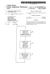
bodying the present invention.
FIG 23 is a flow chart of the ?ow of control of the
conditional device error enqueueing procedure accord
ing to this invention.
FIG. 24 is a ?ow chart of the flow of control of the
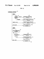
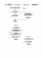
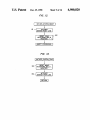
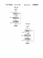
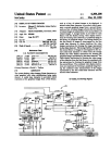
FIG. 2 is a flow chart depicting the ?ow of control in
response to interrupt requests in the circuit of FIG. 1.
according to this invention.
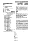
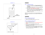
BRIEF DESCRIPTION OF THE DRAWING
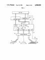
FIG. 1 is a hardware communications adapter em
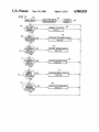
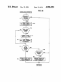
FIG. 3 is a flow chart of the flow of control in the
main control loop during normal processing in the cir
cult of FIG. 1.
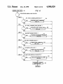
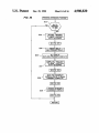
FIG. 4 is a flow chart of the flow of control during
conditional information code enqueueing procedure
DETAILED DESCRIPTION OF THE
PREFERRED EMBODIMENT
Referring to FIG. 1, a communication adapter is
disclosed which embodies the subject invention. Gener
ally, the communications adapter controls data commu
FIG. 3.
nication between host processor 30 and peripheral in
FIG. Sis a flow chart depicting the flow of control in
the
servicing
routine
for
a
KEYBOAR 45 put/output devices such as mouse 31, speaker 32, key
board 33, and key lock switch 34. Keylock switch 34 is
D_RECEIVE_INTERRUPT request detected in
connected to microcontroller 36 by keylock switch line
FIG. 2.
47. The adapter comprises microcontroller 36, periph
FIG. 6 is a flow chart depicting the flow of control in
eral interface circuit 37, command register 38 and de
the servicing routine for a KEYBOARD_TRANS
50 vice drivers/receivers 39.
MIT._INTERRUPT request detected, in FIG. 2.
Microcontroller 36 can be, for example, a 8051 type
FIG. 7 is a flow chart depicting the flow of control in
microcontroller manufactured by Intel Corporation of
the servicing routine for a TIMEOUT_TIMER_IN
Santa Clara, California and peripheral interface circuit
TERRUPT request detected in FIG. 2.
37 can be, for example, an 8255 type peripheral interface
FIG. 8 is a flow chart depicting the flow of control in
the servicing routine for a HOS'IZJNTERRUPT re 55 circuit also manufactured by Intel Corporation.
the processing of low priority work items detected in
quest detected in FIG. 2.
FIG. 9 is a ?ow chart depicting the ?ow of control in
Microcontroller 36 is a dedicated microprocessor
based system including RAM 40, ROM 45, and univer
sal asynchronous receiver/transmitter (U ART) 42. Mi
the servicing routine for a SPEAKELFREQUEN
crocontroller 36 is programmed to provide communica
CY_INTERRUP'T_1 request detected in FIG. 2.
FIG. 10 is a ?ow chart depicting the flow of control 60 tions ports 43 and 44 used to communicate with speaker
in the servicing routine for a SPEAKELFREQUEN
CY_INTERRUPT__0 request detected in FIG. 2.
FIG. 11 is a flow chart depicting the flow of control
in the servicing routine for a UART_INTERRUPT
65
request detected in FIG. 2.
FIG. 12 is a flow chart depicting the flow of control
to perform the work item PROCESS_KEYBOARD_.
FRAME detected in FIG. 3.
32 and keyboard 33, respectively. Port 44 also commu
nicates with keylock switch 34 through keylock switch
line 47. RAM 40 includes command buffer 41 for re
ceiving host commands from command register 38. The
programs disclosed hereinafter reside in ROM 45 and’
microcontroller 36 is capable of initiating system trap
and system reset functions through lines 48 and 49,
respectively.
5
4,980,820
6
power is initially applied to the system, control will
The operation and architecture of the 8051 microcon
troller is described in Intel Corporation publication No.
reside in reset block 63. Control is then transferred to
block 64 where system diagnostics are performed and
where certain initialization procedures are followed.
Control is then transferred to block 66 where the main
210359-001 entitled “Microcontroller User's Manual”
which is expressly incorporated herein by reference by
way of background material.
In operation, microcontroller 36 is susceptible of
processing loop is entered.
Generally, regular processing in the adapter of FIG.
interrupt requests from a total of five sources with each
source assignable to one of either a high priority level or
a low priority level. When an interrupt request is re
1 is occupied by checking the status of each bit of
twelve-bit work queue register 46 shown in FIG. 1
within RAM 40. The sequence of checking the work
queue register is commanded by the programs shown in
FIGS. 3 and 4. Work queue register 46 is divided into
six high priority work item bits and six low priority
work item bits. When checking the work item bits, each
high priority work item bit is checked before the first
ceived, regular processing within microcontroller 36 is
suspended until the interrupt is serviced. A high priority
interrupt can suspend regular processing or the process
ing of any low priority interrupt but cannot suspend the
processing of another high priority interrupt. In con
trast, a low priority interrupt can suspend regular pro
cessing but cannot suspend the processing of any inter
rupt.
low priority bit. Then each high priority bit is again
checked before the second low priority bit, and so forth.
In detail, the main loop is started with control in
decision block 67 where it is decided if any high priority
In the preferred embodiment, the interrupt requests
are initially conditioned by the program depicted in
FIG. 2. The five interrupt requests are detected in a 20 work items, represented by high priority bits in work
queue register 46 (FIG. 1), are in queue. If there are no
known manner by interrupt vectors 50. Interrupt
EXTID is given a high priority and is accepted from the
keyboard. Interrupt TIMERO is given a low priority
and is generated upon over?ow of a timer (not shown)
internal to microcontroller 36 (FIG. 1). Interrupt
EXTII is given a low priority and is accepted from host
30 (FIG. 1). Interrupt TIMERI is given a low priority
and is generated upon over?ow of a different timer (not
shown) internal to microcontroller 36. Finally, inter
rupt SINT is given a low priority and is accepted from
mouse 31 via UART 42 (FIG. 1).
high priority work items in queue, control is transferred
to block 68 where the ?rst low priority work item is
checked. The operation of block 68 is described in detail
below with reference to FIG. 4.
If decision block 67 discovers high priority work
items in queue, control is transferred sequentially to
decision blocks 69-73. If decision block 69 detects that
the first high priority work queue bit WQHD is set,
control is transferred to block 74 and the program steps
shown in FIG. 12 are executed. Control is then looped
back to decision block 67 to decide if any more high
priority work items are in queue.
If decision block 69 detects that work queue bit
WQHO is not set, control is transferred to decision block
70 where work queue bit WQHI is checked. If bit
WQHI is present, control is transferred to block 75
where the program steps shown in FIG. 13 are exe
cuted. As will be described in detail with respect to
When block 50 of the program of FIG. 2 detects an
interrupt request, the contents of a program counter are
pushed onto stack memory and regular processing is
suspended while the proper interrupt servicing routine
is executed. Regular processing, as defined within the
context of the preferred embodiment, is shown in FIGS.
3 and 4 and will be described in detail below.
Referring to FIG. 2, if block 50 detects the high pri
ority interrupt EXTIO, control is transferred to decision
40
FIG. 13, processing is eventually aborted in block 75
and control is not returned to block 67.
block 51 where the keyboard transmit mode is sensed. If
In a manner similar to the operation of decision block
data is to be received from the keyboard, control is
69, decision blocks 71-73 check the status of high prior
transferred to block 52 to execute the program steps
shown in FIG. 5. If data is to be transmitted to the
ity work queue bits WQl-IZ, WQI~I4 and WQHS, respec
keyboard, control is transferred to block 53 to execute 45 tively. If the respective work queue bits are detected by
blocks 71-73, control is transferred to blocks 76-78,
the program steps shown in FIG. 6.
respectively, to execute the program steps shown in
If low priority interrupts TIMERO, EXTII, or SINT
are detected by block 50, control is transferred to blocks
54, 56, or 62, respectively, and the program steps shown '
in FIGS. 7, 8, or 11, respectively, are executed.
If low priority interrupt TIMERl is detected by
FIGS. 14-16, respectively.
Here it should be noted that the preferred embodi
ment does not use high priority work queue bit WQI-I3.
This is because only ?ve high priority work items are
block 50, control is transferred to block 57 where a
necessary to satisfy the speci?c requirements of the
speaker frequency counter (not shown) internal to mi
crocontroller 36 (FIG. 1) is decremented by "1”. Con
trol is then transferred to decision block 58 to determine
preferred embodiment. This fact, and the fact that a
twelve bit work queue register is used with six high
priority bits and six low priority bits should not be con
if the value of the speaker frequency counter is greater
strued to delimit the invention in any manner. It will be
than or equal to zero. If greater than zero, control is
transferred to block 59 where the program steps shown
in FIG. 9 are executed. If equal to zero, control is trans
ferred to block 61 where the program steps of FIG. 10 60
understood by a skilled artisan that the present inven
tion can be used to enqueue work items of an arbitrary
number. In addition, the fact that only two work item
priority levels are described in the preferred embodi
ment will not be construed to place limitations on the
invention. One skilled in the art will appreciate that any
number of work item priority levels may be used with
shown in FIGS. 5-11, the regular program count is
out departing from the spirit and scope of the present
popped from stack memory and placed back into the
program counter so that regular processing can con 65 invention.
Referring now to FIG. 4 to describe low priority
tinue.
work queue bit checking, control begins in block 81
Referring now to FIG. 3, when the communications
having been transferred from block 67 of FIG. 3. Con
adapter shown in FIG. 1 is reset, for example, when
are executed.
At the completion of each of the servicing routines