1
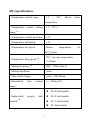
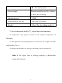
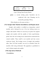
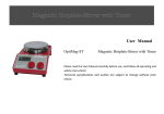
Thermomixer
EGM-206
ExtraGene,Inc.
(I) Introduction to the Product
EGM-206 Thermomixer can conduct thermo-incubation and
vortex mixing experiments simultaneously or independently. It has
instantaneous mixing function and can achieve good mixing and
incubation effects. Experiment operation is simple and flexible and
experiment time can be saved. EGM-206 Thermomixer is the
optimal routine apparatus for incubation, mixing and other sample
preparation tasks in biological laboratory.
(II) Product Features
1.It adopts dry-heat metal bath technology to prevent cross
pollution in the course of water bath.
2.It is driven by brushless variable frequency motor, which is
characterized by stable rotational speed, low noise, no carbon
pollution, and being maintenance-free.
3.Direct contact to heating module can be avoided in the
course of experimental operation to prevent hands from
accidental scald.
4.It is provided with multi-specifications replaceable sample
sink modules to realize simple, flexible and swift operation.
5.The pass of sample sink module matches properly the
appearance of sample tube to prevent oscillation jumping.
1
Samples are oscillated in the form of horizontal vortex
without spattering so the mixing and incubation effects of the
apparatus are good and experimental repetition is enhanced.
6.Temperature control is uniform and accurate and temperature
rise and drop are swift.
7.Operation time is calculated from the time when the
temperature set is reached.
8.Incubation and mixing can be conducted simultaneously or
independently, and working modes of incubation and mixing
can be selected freely. Such three working modes as
continuous mixing, intermittent mixing and series program
controlled mixing are provided for your choice.
9.The apparatus has microcomputer control and program
memory functions, and can save three user programs.
Contents shown on liquid crystal display (LCD) are concise
and remarkable, and control panel operation is simple.
10. It has the function of automatic operation resumption after
power cut-off. In the event of instantaneous power cut-off in
operation, operation will be resumed automatically once
power is supplied.
2
(III) Specifications
1℃ ~ 99℃
Temperature control range
above
room
temperature
to
temperature
Temperature control setting
range
1℃~99℃;
*1
Temperature control precision
±1℃
Temperature uniformity
±1℃
Temperature rise speed
Room
99℃≤8min
Temperature drop speed
Mixing frequency
99℃ to room temperature
*2
≤15min
*3
300~1200 r/min; 0
Mixing amplitude
3mm
Time control range
1min~99h 59min
Intermittent
time
control
1s~99min 59s
range
Replaceable
module
sample
sink
*4
3
96×0.2ml module
48×0.5ml module
24×1.5ml module
24×2ml module
Power supply
24×5ml module
Please properly use the voltage
to meet local charge
Maximal power
350W
Dimensions (L×W×H)
340×258×170 (mm)
Weight
About 7kg (including module)
*1 The set temperature shall be 1℃ higher than room temperature.
*2 Temperature drop speed is related to the ambient temperature of
laboratory.
*3 The upper limit of mixing frequency is related to the weight of sample
sink modules (Table 1)
*4 Sample sink modules of other specifications can be customized.
Table 1 The Upper Limit of Mixing Frequency of Replaceable
Sample Sink Modules
4
Sample sink module
The upper limit of mixing
frequency
48×0.5ml
centrifugal
1100 r/min
96×0.2ml
PCR board
1100 r/min
24×1.5ml
centrifugal
1100 r/min
centrifugal
1100 r/min
centrifugal
600 r/min
tube
tube
24×2ml
tube
24×5ml
tube
(IV) Working Modes
Operation modes include routine mode and series
program controlled mode. When “—∶—” is displayed at the
right upper corner of LCD, routine mode is used; and when
“P∶X” is displayed, series program controlled mode is adopted.
In such two operation modes, any of continuous mixing mode,
intermittent mixing mode, independent mixing mode, and
independent incubation mode can be set. In routine mode,
5
intermittent mixing function can be opened or closed by pressing
CH switchover key.
(V) Operation and Display Panel
1.
. Operation and display panel
Figure 1 Operation and display panel
START/STOP ── Start /Stop key
INV ── Key for setting intermittent time of intermittent
mixing
PRO ── Key for setting series program controlled mixing
incubation
CH ── (Setting) switchover key/(Operation) pause key
▲ ── Parameter settings up
▼ ── Parameter settings down
TEMP ── Incubation temperature setting or room
temperature selection
MIX ── Mixing frequency setting or in non-operating
6
condition
TIME ── Incubation/mixing time setting
2. LCD window
2.1 Continuous mixing and incubation display
xx/xx℃
xxhxxmin
Figure 2
xxxxrpm ──
- : - LCD
INV: OFF ***
Continuous Mixing and Incubation Display Window
XX/XX℃
℃ ── The set temperature is shown on the left,
and the actual temperature is shown on
the right (℃).
XXhXXmin ── The set time is shown in non-operating
condition, and remaining operation time
is shown for count down after startup
(hour: minute)
XXXXrpm ── Oscillation frequency (rpm)
— — ── Routine operation mode
INV:OFF ── Continuous mixing and incubation mode
(intermittent operation OFF)
EG ── That EG letters are all ON means non-operating
condition, and that 3 letters are ON in turn
7
means mixing operation status.
2.2 Intermittent mixing and incubation display
a) Intermittent mixing time setting
* xxminxxs R
xxminxxs S
*
xxminxxs
xxminxxs
R
S
Figure 3 Intermittent Mixing Time Setting
* ── Switchover indication symbol, showing the
selected setting target
R ── Intermittent mixing operation time (minute:
second)
S ── Intermittent mixing stop time (minute: second)
b) Intermittent mixing and incubation display
xx/xx℃ xxxxrpm
-:xxhxxmin INV:ON ***
Figure 4 Intermittent Mixing and Incubation Display Window
INV: ON ── Intermittent mixing and incubation mode
Other displays are the same as above.
2.3 Series program controlled mixing and incubation
display
If two programs in series (continuous or intermittent) are
needed for mixing and incubation, temperature, frequency
8
and time (and intermittent time) parameters may be set for
each program separately, and programs will be named
automatically as program P1 and program P2 in the order of
operation. When program P1 runs, window P1 will be
displayed; and the system will switch over to window P2
automatically upon completion of program P1.
xx/xx℃ xxxxrpm
xxhxxmin INV:OFF
P:1
***
xx/xx℃ xxxxrpm
xxhxxmin INV:OFF
P:2
***
Figure 5 Series Program Controlled Mixing and Incubation Display Window
PRO
──Series
program
controlled
mixing
and
only
with
incubation mode
P1 ── The first program is running
P2 ──The second program is running
Other displays are the same as above.
2.4 Independent incubation display
xx/xx℃
xxh:xxm
0000rpm
INV:OFF
-:***
Figure 6 Independent Incubation Display Window
0000rpm
──
Independent
incubation
temperature control function without mixing
9
Other displays are the same as above.
2.5 Independent mixing display
--/xx℃
xxhxxmin
xxxxrpm
INV:OFF
-:***
Figure 7 Independent Mixing Display Window
--/XX℃
℃ ── -- means room temperature is selected. XX is
the actually measured value of room
temperature. Other displays are the same
as above.
2.6 Unlimited mixing display
XX/xx℃
--h:--m
xxxxrpm
INV:OFF
-:***
Figure 8 Unlimited Mixing Display Window
--h:--m ── -- means unlimited operation. Operation will
not stop until stop key is pressed
manually.
Other displays are the same as above.
2.7 Mixing pause display
In the course of operation, mixing may be paused only by
pressing CH key, as shown in the following figure:
10
--/xx℃
xxhxxmin
pause
INV:OFF
-:***
Figure 9 Mixing Pause Display Window
pause ── means mixing pause. Operation can be
conducted after stop. Running can be
resumed by pressing CH key.
Other displays are the same as above.
(VI) Sample Sink Module Installation and Replacement
Sample sink module is installed on temperature control
module, and is fastened by use of the two locking screws on
sample sink module. When it is necessary to replace the original
sample sink module with the module of other specifications,
please loose the two locking screws anticlockwise and detach the
current module. Then, install a new module and turn screws
clockwise firmly. The locking screws of sample sink modules
other than 96×0.2ml module can not be detached from the
modules after being unfastened. The apparatus is prohibited to
run if without sample sink module.
(VII) Operation Methods
1. Installation
11
1.1 The work bench on which the apparatus is placed should be
flat and rigid, and the four rubber feet of the apparatus should be
fully in touch with the surface of work bench.
1.2 Sufficient clearance should be reserved around the apparatus
to facilitate ventilation and direct sunlight should be avoided.
1.3 Power supply please properly use the voltage to meet local
charge.
1.4 It should be checked whether 5A cartridge fuse has been
installed in the fuse box at the back of the apparatus. If the fuse
is broken, a new cartridge fuse of the same specifications should
be replaced.
2. Operation methods
2.1 Continuous mixing and incubation operation
1) Select a sample sink module for use, install it on temperature
control module, and fasten two locking screws.
2) Press the power switch at the back of the apparatus. At the
time, operation parameters of last time are displayed on display
window.
3) After power on, “INV: OFF” should be shown on the display
window. If “INV: ON” is shown instead, CH switchover key should
be pressed. (CH key has the function only when “—:—” is shown at
12
the right upper corner of LCD in routine mode. In series program
controlled mode, P1 and P2 are switchover keys.)
4) Press the triangular key under TEMP until the desired
temperature setting is shown on the left.
5) Press the triangular key under MIX until the desired
rotational speed setting is shown. The rotational speed setting of the
module must be no higher than the upper limit of allowable mixing
frequency as prescribed in Table 1.
6) Press the triangular key under TIME until the desired mixing
and incubation time is shown.
7) Press START key (with one prompt sound). At the time, the
apparatus begins to run automatically as per the set parameters and
*** letters are ON in turns. If the set time shown on the window
decreases till 0, the apparatus will stop automatically (with three
prompt sounds), and EG letters are all ON.
8) If it is necessary to pause operation temporarily, the apparatus
will enter standby status by pressing STOP key (with two
prompt sounds).
9) Upon completion of operation, the apparatus should be
switched off. Before the apparatus is not in use for a long time,
its power cord should be unplugged.
13
2.2 Intermittent mixing and incubation operation
1) After power on, “INV: ON” should be shown on the display
window. If “INV: OFF” is shown instead, CH switchover
key should be pressed.
2) Intermittent time setting window is shown by pressing INV
key. Press CH key for switching over the setting windows
between the operation time (R) or stop time (S) of
intermittent mixing. Press the triangular key under TIME
to set operation time (R) or stop time (S). After setting,
press INV key once more for confirmation.
3) Press START key to enter intermittent mixing and incubation
working condition.
2.3
Series program controlled mixing and incubation
operation
1) At first, press PRO programming key to show window P1
first, and set operation parameters of program P1:
incubation temperature, mixing frequency, mixing and
incubation time (and intermittent time).
2) Then, press CH switchover key to show window P2, and set
operation
parameters
of
program
P2:
incubation
temperature, mixing frequency, mixing and incubation
14
time (and intermittent time).
3) Press START key. The apparatus will make P1+P2 in
series automatically and complete running.
2.4 Independent incubation operation
Set mixing frequency as 0. Other operations are the same
as those of continuous mixing and incubation.
2.5 Independent mixing operation
Set temperature – (press temperature down key until
temperature setting value is lower than 1). It denotes that
mixing is conducted at room temperature, and temperature
control system does not function. Other operations are the
same as those of continuous mixing and incubation or
intermittent mixing and incubation.
(VIII) Standard Delivery Configurations
Standard delivery configurations of apparatus: one mainframe, one
48×0.5ml sample sink module, and one set of transparent sample
bracket. Sample sink modules of other specifications need to be
ordered or replaced separately.
(IX) Cautions
1. The work bench on which the apparatus is placed should be
highly rigid and should not generate resonance. Sufficient
15
clearance should be reserved around the apparatus to facilitate
ventilation and direct sunlight should be avoided. The four
rubber feet of the apparatus should be in touch with the surface
of work bench steadily.
2. Power supply please properly use the voltage to meet local
charge. It is strictly prohibited to wrongly use AC 380V power
supply to avoid apparatus damage.
3. If the fuse is broken, 5A cartridge fuse should be replaced.
4. Two surfaces on which sample sink module is to be installed
should be cleaned, and locking screws should be fastened. The
apparatus is prohibited to run if without sample sink module.
The apparatus may run when transparent sample support is
installed on it. However, on account of fast movement design,
abnormal sound will give out if rotational speed is set too high.
Therefore, the apparatus should run at a low speed when
transparent sample support is used.
5. Check whether centrifugal tube matches properly the pass of
sample sink module. If not, high-quality centrifugal tube
meeting standards and criteria should be used.
6. Sample sink module should be stored in a ventilated dry place.
If the pass of the module accidentally contacts sample liquid, it
16
should be washed with water and then dried to prevent the
module from corrosion. Sample sink module should be washed
with neutral detergent and be disinfected to prevent cross
pollution.
7. The mixing frequency for each sample sink module should be
no higher than its allowable maximal mixing frequency. At the
time of micro-mixing, high frequency is not the sole factor
deciding perfect mixing.
8. Operation parameters should be set in standby condition.
Program parameters must not be modified in the course of
operation. Mixing time is counted down when the set
temperature is reached.
9. When temperature setting is -- (room temperature),
temperature control system stops working.
10. In case of any fault in control system, please contact the
company for checking and repairs.
ExtraGene,Inc.
Address: 1424Yukon St.Davis,California 95616
TEL :530-753-2363
FAX: 530-792-8352
E-mail:[email protected]
Web Site:www.extragene-web.com
17