1
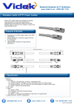
12 Volt Screwdriver Antenna
Memory Controller
Model 12PRSDC
User Manual
Document Rev 1.0
Warranty
All products sold by Portable Rotation are warranted against defects in material and
workmanship for a period of 1 year from the date of shipment within North America,
and for a period of one (1) year from the date of shipment to outside of North
America. If you believe this product you have purchased has a defect in material or
workmanship or has failed during normal use within the warranty period, please
contact Portable Rotation at the below listed contact information for assistance. If
product repair or replacement is necessary, the Customer will be solely responsible
for all shipping charges, freight, insurance and proper packaging to prevent breakage
in transit, whether or not the product is covered by this warranty. All shipments of
repaired or replaced products by Portable Rotation will be F.O.B. from Roseville
California, USA.
This warranty does not apply to defects resulting from any Customer actions, such as
mishandling, improper interfacing, operation outside of design limits, misapplication,
improper repair, or unauthorized modification; breaking the Warranty Seal voids all
stated warranties. No other warranties are expressed or implied. Portable Rotation
liability shall be limited to the actual purchase price of any defective unit to which a
claim is made, and shall in no event include the Customer's manufacturing costs, lost
profits or goodwill, or any other direct, indirect, special, incidental or consequential
damages whether based on contract, tort or other legal theory. Portable Rotation is
not responsible for any Damage to or caused by the installed Antenna in any use
case.
In general: We do not warranty against Stupid but if you have an issue we are here
to help.
Contact Information
For Sales inquiries:
http://[email protected]
For Support:
http://[email protected]
Shipping Address:
Portable Rotation
1040 Foothills Blvd, Ste: 103
Roseville CA 95747
Website: http://www.portablerotation.com
Copyright 2014-15 © Portable Rotation
Page 2
Introduction
Thank you for purchasing the Portable Rotation 12 Volt Screwdriver Antenna Memory
Controller, Model 12PRSDC. This system has been designed to support all 12 Volt
Screwdriver type antennas that provide a rotational timing pulse.
This system is built with a simple to use User Interface allowing easy operation while
still offering features like Automatic Calibration and 24 User programmable Memories
Locations. When not tuning, both the count position and an 8 Character User
Settable Text Messages are displayed.
The heart of the system is a microprocessor that takes user input from 3 buttons and
then controls the antenna motor direction, displaying position count and other
information on a LCD screen. User entered information is saved in internal memory
along with position count data; the controller can be turned off (removed from
power) when not being used to conserve power without the loss of User or Position
data.
Key Features
•
•
•
•
•
•
•
•
•
•
•
•
Easy 3 button user interface with backlight 2x8 character LCD and 2 Notification
LEDs
Position count of up to 9999 turns
PWM motor control with two user controlled turning speeds
Manual Up and Down Control
24 User Defined Memory Locations
Automatic Position Control using stored Memory Data
User programmable display message
User initiated Automatic Calibration
Motor Turning Jam detection with auto stop
4 Conductor Cable (5 foot length provided) – Optional Tarheel Connector
USB Computer interface supports the Upload/Download of Memory and User
data to and from a PC.
40mA idle current, and up to 2Amp peak current supported
Specifications
•
•
•
•
•
•
10.0 Volt to 15 Volt DC Operation (12 Volt Nominal)
40maA idle current.
24 Programmable User Memories
Will control up to a 2 Amp motor stall load
Controller Weight: 8 Ounces.
4 conductor Interface cable – Recommended Gauge Size is 18guage stranded
Included Items
The following items are included as part of the Screwdriver Antenna Memory
Controller system:
• 12PRSDC Screwdriver Antenna Memory Controller.
• 5 Ft - 4 Conductor Cable with matching screw type connector for attachment to
Controller.
• 5 Foot Pigtail Power cable (2.1mm x 5.5mm, Center Pin Positive).
• 3 Foot USB Cable.
• This Users Document.
Before First Use
Inspect the contents of the box and verify that the contents of the box match the
above list.
In a mobile installation there can be strong RF-Fields present; make sure the Power
supply, antenna feed line and screwdriver antenna control cable are properly
decoupled. The Controller inputs are filtered and the enclosure is aluminum, but
strong unmanaged RF fields may cause erratic operation.
You will need to attach a 12 Volt power source to the ends of the provided pigtail
cable. Make sure to NOT cross the Positive lead with the Negative Lead. The Positive
lead on the provided power cable has the White Stripe.
Note: The controller electronics will work at a voltage as low as 6 Volts, but there is
not enough energy to operate a 12 volt Screwdriver’s DC motor. 9 Volt operation is
not recommended when using large screwdriver units as there may not be enough
energy for reliable rotation of the motor.
Copyright 2014-15 © Portable Rotation
Page 2
Installation
Using the supplied barrel style cower connector and Screwdriver Antenna 4 Conductor
adapter cable, connect the controller to 12VDC power and the Screwdriver Antenna
Unit. See Page 12 for connection details
Turn on the controller; the following start up messages are displayed with the final
display showing the user configurable 8 character top line and the last known
antenna position:
Portable
Rotation
Model
12PRSDC
PTBL RTN
CNT:0000
Default Start up Messages
Before use, you must perform a Calibration Operation so the controller can learn the
number of turns supported by the Screwdriver Antenna and for it to locate the fully
retracted location.
Operation
New Installation Configuration - Initial Antenna Calibration
When you first install the controller it needs to discover the maximum number of
turns the Screwdriver Antenna supports and to find the retracted or starting location.
The calibration sequence will cause the Screwdriver Antenna to retract to its
minimum position where it will set the initial count location to 0000. Once the
retracted location is found the controller reverses direction and turns the Screwdriver
to the Maximum or extended position. Once found the controller then knows the
count associated to the fully extended position. The controller will then reverses
direction and returns the Screwdriver Antenna to the fully retracted position.
To initiate the Calibration Sequence Turn on the Controller while holding the MODE
button down until the below message is displayed. At that time, release the button
and the sequence will start.
Re-Calib
Turning
The Green LED will turn on and the motor will start to move the antenna down.
Depending on your Screwdriver Antenna design, once the bottom or retracted
location is reached the controller will sense the motor stall condition then stop and
change directions. If the motor in the antenna continues to turn once reaching the
full retracted position (a slip clutch design) or at any point before reaching the
minimum position, you can press any button to manually set the minimum or 000
count position.
Calibration continues with the motor turning the Screwdriver Antenna to the fully
extended position where the motor stall condition is again detected and the max turn
count is saved to memory. Again, you can press any button to stop the max turn
operation early and set a max turn less than the stall turn position. The Controller
Copyright 2014-15 © Portable Rotation
Page 3
will return the Screwdriver Antenna to the newly found fully retracted position and
enter the normal operating mode. At this point, the controller will be calibrated to
your antenna
Note: The Calibration Operation does not clear User Memory or User Text.
Setting your Call Sign / Vanity Text
The 12PRSDC Screwdriver Memory Controller allows you to set, and will display
during idle time where the controller is not turning the antenna, 8 Characters of your
choice, on the top line of the display. This can be your call sign, antenna information,
or any other message you want displayed. This information can be changed as often
as you like.
To set the text message: While holding down the CCW button [left Button] turn On
the Controller. Continue holding the button until the “Ent Call” message is displayed,
then Release the button. The bottom line will now display the current message text
and the first character position will show that it is ready for input as it will be
underlined. Use the CCW and CW buttons to step forward or backwards through the
Letters and Numbers, pressing the MODE button after the correct character is
selected. You must do this operation for all 8 character positions. If no change is
needed, just press the MODE button to move to the next character position.
Ent Call
N7IPY
Enter new Text for each of
8 character positions for a
new message
SCREWDRV
CNT:0170
After entering all 8 characters the display will refresh showing the new user selected
text on the top display row and the current antenna count on the bottom.
Note: Only Upper Case Letters can be entered in this mode. Lower case can be used
when editing and uploading settings through a computer
Normal Operations
Once the initial calibration is complete, the 12PRSDC Screwdriver Memory Controller
is ready to control your Screwdriver Antenna system. There are two (2) modes of
operation; Manual Turn and Memory Turn.
Manual Turn Mode
To use this mode of operation, press and hold the CCW (Counter Clockwise) button to
retract the Screwdriver Antenna or the CW (Clockwise) button to extend the
Screwdriver Antenna until the Count on the LCD displays the Turn Count Number you
want. For a slower tuning rate, press and hold the MODE button while pressing the
CCW or CW buttons. This enables the half speed turn option. Release the MODE
button to return to a full speed turn. During any turn operation the GREEN LED is on
indication that a turn is in progress.
Copyright 2014-15 © Portable Rotation
Page 4
N7IPY
CNT:0130
Turning
CNT:0131
N7IPY
CNT:0188
Clockwise turn done by holding the “CW” button down. During the turn the current count is
displayed.
N7IPY
CNT:0100
Turning
CNT:0099
Min Cnt
CNT:0000
Counter Clockwise turn done by holding the “CCW” button down. During the turn the current
count is displayed. Upon reaching a count of 0000. The “MIN CNT” message is displayed.
When reaching the Max Count limit that was set during the Calibration process,
turning is stopped and a message is displayed. Once the Max count is reached, the
only turn allowed is in the opposite direction, retracting the antenna element.
Likewise once reaching the full retracted position of 0000, the turn operation is
stopped and only extending the antenna is possible. The controller protects the
antenna mechanically by limiting the number of times you can stall the motor at end
limits to only when the calibration is performed.
When a turn is in process, the new count value is saved to nonvolatile memory at
every count so no position data is lost in the event of power loss. When finished with
the tuning process, you can turn off the Controller to conserve power. No user data
is lost when power is removed as the data is stored in Nonvolatile FLASH memory.
Memory Turn Mode
There are 24 memory locations to store user defined Turn Counts and Memory
Channel Names. Once an antenna position is found that you want to be able to
return to automatically, you can save the count information and change the memory
channel name to be descriptive of that position setting.
How to Program Memory
To save the current memory position, with the Controller on and in the normal
operating mode, press and release both the CCW and CW buttons at the same time.
The message ‘Prog Mem’ is displayed on the top line and ‘NoChange’ is displayed on
the bottom line. Use the CCW and the CW buttons to step through the memory
channels. If you decide to not save the current position, use the CCW or CW button
to step through the memory listings until the “NoChange” message is displayed then
press the MODE button. This will return the controller back to its normal operating
mode.
To save your data, using the CW or CCW buttons select the memory channel and
press the MODE button. You can now change the 8 character channel label text the
same way as done for setting the Call Sign / Vanity Text message. If you are
keeping the same text, just press the Mode button 8 times to step through the
character locations. After making the changes to the Memory Channel Label (or not),
the 8th press of the MODE button will cause the data to be saved and operation
returns to the Normal Operating Mode. If you need to abort the Save Operation,
prior to the 8th MODE button press, you can power cycle the controller. No data is
changed prior to the 8th Mode button press.
Copyright 2014-15 © Portable Rotation
Page 5
How to Memory Turn
To change the screwdriver antennas physical position to a previously saved location
saved in a memory channel, press and hold the MODE button. Using the CCW or CW
button, step through the memory locations until you locate the Channel Name you
are looking for and then pressing the MODE button will initiate a Memory Turn
operation. To exit prior to starting the tune, use the CCW or CW buttons to step to
the “NoChange” message and press the MODE button.
Aborting a Memory Turn Operation
At any time during the Memory Turn process, you can abort the turn operation by
pressing the MODE button. The turn will stop immediately saving the current position
to memory.
Turn Stoppage – Antenna Jam
If during a Memory Turn or Manual Turn operation the Screwdriver Antenna motor
stops turning, the controller will remove the power to the motor and displaying an
error message on the LCD and turn on the RED led with a constant ON condition.
ANT JAM!
CNT:0123
Motor Turn is blocked while doing
a CCW turn at count 0123.
ANT JAM!
CNT:0021
Motor Turn blocked while doing a
CW turn at count 0021.
If a Motor Jam does occur, stop any further attempts at antenna tuning and inspect
the antenna for any physical problems.
To clear the condition after you have resolved the physical condition causing the
motor JAM, you can turn the screwdriver antenna in the opposite direction that
caused the JAM or just power-cycle the Controller. The antenna jam state is not
saved over a power Off/On cycle.
Reset to Default Settings
The controller can be reset to the default out of box settings, clearing any user
entered settings and resetting all internal stored states. To reset the Controller, turn
on the controller while holding down all 3 buttons until the sign on messages are
displayed. The Firmware Version will be displayed and you will be asked if you want
to reset the Controller. Press the CCW button for Yes or the CW button for No. If
yes, the controller then returns to normal operation, with factory defaults. All User
saved Memory Data is erased and a new Calibration operation will be required before
use.
Copyright 2014-15 © Portable Rotation
Page 6
Send and Receive User Memory Data
The 12PRSDC Screwdriver Antenna Memory Controller has a USB port that is used to
save and load Memory Data from a computer system. The data format is simple
ASCII text so it can be edited easily. The data can be captured, edited and
programmed back to the controller at any time. The 12PRSDC Screwdriver Controller
is attached to a computer system using the USB Type-B jack found on the front of the
Controller.
Controller Serial Protocol is:
9600 baud, 1 Start, 1 stop, No Parity, No Handshake
Saving Controller Data
To send memory data from the Controller to your PC, use your favorite serial
communication application to capture the ASCII text.
To transfer the memory data, Turn On the controller while pressing the CW button.
The Serial Menu is displayed.
Serial
Snd Rvc
Turn On while Holding
the CW Button
Serial
Sending
Release the CW Button and then press
the CW Button to Send Data
PTBL RTN
CNT:0015
When finished sending, operation
returns to manual control mode
On your PC start your communications application, setting the proper serial
properties and open the Receive Buffer. When the PC is ready to capture data, press
the CCW button to send the memory data to the PC. The message Sending is
displayed and the Red (Data) LED will flash to show data transfer. The operation is
fast so the LED on time is short. Once the data has been sent the controller returns
to the normal operating mode. On the PC, save the captured data to a text file.
Note: All testing was done using “Tera Term” which is an open source terminal
emulation communications program. The home page for Tera Term with links for
download and documentation is currently at:
http://ttssh2.sourceforge.jp/index.html.en
Programming - Receiving Data
To program the Controller with edited memory data from your PC; Turn on the
controller while pressing the CW button. The Serial Menu is displayed. Release the
button.
Serial
Snd Rvc
Turn On while Holding
the CW Button
Serial
Receive
Release the CW Button and then press
the CCW Button to Receive Data
Copyright 2014-15 © Portable Rotation
PTBL RTN
CNT:0015
When finished sending, operation
returns to manual control mode
Page 7
Press the CW button to set the controller in the Serial Receive mode. The controller
now waits for data from the host computer. Next go to your PC and using your serial
communications application, start the serial data transfer. The Red LED will flash as
data is received from the PC and after successfully receiving the data the controller
will save it to nonvolatile memory and then returns to the default Manual Operating
mode.
You can verify proper memory programming by either manually stepping through the
memory channels and verifying the Memory Labels are correct and the antenna
moves to the count that was edited in the text file or resend the serial data as
explained above and compare the new capture to the data that was previously sent
to the controller. If the data file is not formatted properly the data transfer will fail.
The serial protocol is very simple and there is limited error checking and correction
provided in the controllers programming. In the event that the Receive function fails,
power cycle the controller to clear any hang condition. If something fails in the
transfer, the controller will appear to hang as it may be waiting for data or the
transfer file has an error in its format. Again, a power cycle will clear the hang
condition.
Data Format
The data sent and received is a simple 346 byte ASCII file with the following format:
Start Character: ‘[’
Call Sign Text: ‘8 Characters Text’,
Memory Channel 01:‘8 Character Label’,’xxxx’,
Memory Channel 02: ‘8 Character Label’,’xxxx’,
….
Memory Channel 24: ‘8 Character Label’,’xxxx’
End Character: ‘]’
Where: xxxx = ASCII Numeric Count
All data fields are separated by a comma ‘,’. All Message fields are 8 characters, and
all count fields are 4 characters, so leading 0s are required for values under 1000;
i.e. ‘0014’. The Start Character of ‘[’ must be the first value sent and the End
Character of ‘]’ must be the last character sent. The start and stop character should
not be used in user entered text in the modified text file as it will cause the transfer
and save operation to fail.
Example Text File:
[12345678,160Mtr L,0120,160Mtr H,0115,80Mtr L, 0110,80Mtr H ,
0105,60Mtr C1,0100,60Mtr C2,0095,60Mtr C3,0090,60Mtr C4,
0085,40Mtr L ,0080,40Mtr H ,0075,30Mtr L ,0070,30Mtr H ,
0065,20Mtr L ,0060,20Mtr H ,0055,17Mtr L ,0050,17Mtr H ,
0045,15Mtr L ,0040,15Mtr H ,0035,12Mtr L ,0030,12Mtr H ,
0025,10Mtr L ,0020,10Mtr H ,0015, 6Mtr L ,0010, 6Mtr H ,
0005,]
Copyright 2014-15 © Portable Rotation
Page 8
FTDI Driver Requirements
To use the onboard USB interface your computer needs to have the FTDI Virtual COM
Port driver loaded. This driver is available on the FTDI Web Site at the following URL:
http://www.ftdichip.com/Drivers/VCP.htm
From this location select the driver based on you Operating System and install as
instructed by FTDI.
Connection Information
The provided cable is a 4 conductor, 18 Gauge, 7 strand cable using a female Philco
Mic connectors at one end.
Pin 1 – Motor (+/-) - RED Wire
Pin 2 – Motor (-/+) - BLACK Wire
Pin 3 – Sensor (+) - YELLOW or WHITE Wire
Pin 4 – Sensor (-) - BLUE or GREEN Wire
Below are the connection details for the Screwdriver Controller to Screwdriver
Antenna Connection.
Required Cable Connector: 4-Pin MIC connector: Philco P61605
Caution should be used if making your own cable as connecting the Motor Drive pins
to the rotational sensor may damage the controller and your Screwdriver Antenna
requiring replacement of the Controller and/or the Screwdriver Antenna Unit.
Copyright 2014-15 © Portable Rotation
Page 9
Quick Reference Guide
Power On Commands
Enter User Text
Power On while holding CCW button
Initiate Calibration
Power On while holding MODE button
Enter Serial Transfer Mode
Power On while holding CC button
Display Firmware Revision and Optional Factory Reset
Power On while holding CCW + MODE + CW buttons
Normal Operating Commands
Turn CCW (Retracting Antenna)
Press CCW button
Pressing MODE at the same time will slow the turn
Turn CW (Extending Antenna)
Press CW button
Pressing MODE at the same time will slow the turn
Select Memory Channel
Press MODE button
Use CCW and CW to select memory channel
Press MODE button to start
Select and Program Memory
Press CCW + CW buttons
Includes setting Memory Channel Text
Use CCW and CW to select memory channel
Press MODE to enable edit more
Copyright 2014-15 © Portable Rotation
Page 10