1
SAFEPATH
Operation and Installation
Manual
Models:
SAPE-1AB
SAPE-1AR
SAPE-2AB
SAPE-2AR
273 Branchport Avenue
Long Branch, NJ 07740
Telephone: 800-631-2148
Fax: 738-222-8707
www.wheelockinc.com
Part Number A83361 Revision C
P83331
Thank you for using our products. Use this product according to this instruction manual. Please keep
this instruction manual for future reference.
ANY MATERIAL EXTRAPOLATED FROM THIS DOCUMENT OR FROM WHEELOCK MANUALS OR OTHER DOCUMENTS
DESCRIBING THE PRODUCT FOR USE IN PROMOTIONAL OR ADVERTISING CLAIMS, OR FOR ANY OTHER USE,
INCLUDING DESCRIPTION OF THE PRODUCT'S APPLICATION, OPERATION, INSTALLATION AND TESTING IS USED AT
THE SOLE RISK OF THE USER AND WHEELOCK WILL NOT HAVE ANY LIABILITY FOR SUCH USE.
Conventions Used in This Manual
This manual uses the following conventions for notes, cautions, and warnings.
NOTE: All CAUTIONS and WARNINGS are identified by the symbol
. All warnings are printed in bold capital letters.
CAUTION:
Indicates a potentially hazardous situation which, if not avoided, could result in minor or moderate injury. It may
also be used to alert against unsafe practices.
WARNING:
INDICATES A POTENTIALLY HAZARDOUS SITUATION WHICH, IF NOT AVOIDED, COULD RESULT IN
PROPERTY DAMAGE AND SERIOUS PERSONAL INJURY OR DEATH TO YOU AND OR OTHERS.
Copyright 1998, 1999 Wheelock, Inc. All rights reserved.
P83331
SAFEPATH Manual
Rev. C April 1999
Preface
The SAFEPATH panel can provide playback only or record and playback capability, depending upon how the panel is configured.
Panels configured with a DX-100 digital voice module have playback only capability. Panels configured with a DX-200 digital voice
module have record and playback capability.
The SAFEPATH panel does not sense an emergency condition or hazardous fires; it is only a part of a system that does sense such
conditions. The SAFEPATH panel, when activated by a control panel, provides a pre-recorded tone and/or voice message(s) to
notification appliances. When used as part of a protective signaling system, the SAFEPATH panel must be properly connected to a
compatible control panel that has been approved by a nationally recognized testing laboratory ("LISTED") and to LISTED compatible
notification appliances for proper operation.
PERSONNEL PROPERLY QUALIFIED IN THE APPLICATION AND USE OF LIFE SAFETY EQUIPMENT ("QUALIFIED
PERSONNEL") MUST READ THIS MANUAL CAREFULLY BEFORE PERFORMING ACTIONS TO SPECIFY, APPLY, INSTALL,
MAINTAIN AND OPERATIONALLY TEST SAFEPATH PRODUCTS IN ACCORDANCE WITH THE INSTRUCTIONS IN THIS
MANUAL.
The SAFEPATH panel has been Listed by UL as a four circuit panel. Each message must be recorded on each output channel and
then selected to play through each output circuit when required.
WARNING:
•
•
•
IF SAFETY PRECAUTIONS, INSTALLATION AND TESTING INSTRUCTIONS ARE NOT PERFORMED
PROPERLY, THE SAFEPATH PANEL MAY NOT OPERATE IN AN EMERGENCY SITUATION WHICH
COULD RESULT IN PROPERTY DAMAGE AND SERIOUS INJURY OR DEATH TO YOU AND/OR OTHERS.
DO NOT assume any installation, operation and testing details not shown in this manual.
The SAFEPATH panel should only be operated with covers properly in place.
KEEP THIS MANUAL WITH THE SAFEPATH PANEL FOR FUTURE REFERENCE for the life of the system and make it
available to all qualified personnel who operate, test, maintain, or service SAFEPATH products. We strongly recommend that
such personnel read and understand the entire manual.
The SAFEPATH panel WILL NOT WORK WITHOUT POWER. The SAFEPATH panel is powered by 120VAC. Back-up power is
provided by 24VDC batteries. If both sources of power are cut off for any reason, the SAFEPATH panel will not provide the desired
tone and/or voice warning.
WHEELOCK EXPRESSLY DISCLAIMS ALL LIABILITY FOR THE CONTENT, CLARITY AND LANGUAGES OF, AND OUTPUT
CHANNEL AND PRIORITY LEVEL ASSIGNED TO, ANY AND ALL MESSAGES. IT IS ESSENTIAL THAT YOU HAVE MESSAGE
CONTENT AND LANGUAGE, SEQUENCE, OUTPUT CHANNEL AND PRIORITY ASSIGNMENTS REVIEWED AND APPROVED
BY QUALIFIED LEGAL AND SAFETY ADVISORS, QUALIFIED REPRESENTATIVE(S) OF OWNER(S) AND USER(S), AND
AUTHORITIES HAVING JURISDICTION.
CAUTION:The SAFEPATH printed circuit boards are sensitive to static electricity and have delicate components mounted on
them. Before handling either a board or any component on a board, discharge any static electricity from your body by touching a
grounded object such as a metal screw which is connected to earth ground. Handle the board by its edges, and be careful not to
twist or flex it. The SAFEPATH panel is to be installed in a static free area and the user is to properly attach grounded wrist straps
before touching any static sensitive areas. After handling SAFEPATH printed circuit boards, the SAFEPATH panel should be tested
in accordance with the “System Checkout” section of this “Installation” section of this manual to verify that the printed circuit boards
are undamaged and functioning properly.
COMPLY WITH ALL OF THE LATEST APPLICABLE CODES, REGULATIONS, LAWS, STANDARDS, GUIDELINES.
For emergency, hazardous, security, life safety and fire protective signaling system applications, the SAFEPATH products must be
used within their published specifications and only with a LISTED compatible control panel in accordance with sound engineering
judgment and the instructions of the manufacturer and in accordance with local, state and federal codes, regulations and laws. The
SAFEPATH products must be PROPERLY specified, applied, installed, operated, maintained and operationally tested in accordance
with these instructions at the time of installation and at least twice a year or more often as required by local, state and federal codes,
regulations and laws. Installation, testing and maintenance must be performed by qualified personnel for proper operation in
accordance with all of the latest National Fire Protection Association (NFPA), Underwriters' Laboratories (UL), National Electrical
Code (NEC), Occupational Safety and Health Administration (OSHA), local, state, county, province, district, federal and other
applicable building and fire standards, guidelines, regulations, laws and codes including, but not limited to, all appendices and
amendments and the requirements of the local authority having jurisdiction (AHJ).
WARNING:
SAFEPATH Manual
Rev. C April 1999
IF THE PROTECTIVE SIGNALING SYSTEM SOUNDS AND/OR FLASHES, IT IS A WARNING OF A
POSSIBLY SERIOUS SITUATION AND REQUIRES YOUR IMMEDIATE ATTENTION.
Sheet 4 of 78
NOTE: This equipment has been tested and found to comply with the limits for a Class A digital device, pursuant to Part 15 of the
FCC Rules. These limits are designed to provide reasonable protection against harmful interference when the equipment is
operated in a commercial environment. This equipment generates, uses, and can radiate radio frequency energy and, if not
installed and used in accordance with the instruction manual, may cause harmful interference to radio communications. Operation
of this equipment in a residential area is likely to cause harmful interference in which case the user will be required to correct the
interference at his own expense.
For the SAFEPATH panel to properly operate. it must be properly connected to a listed compatible and properly operating control
panel that controls its activation. The operation and electrical ratings of such control panel must be compatible with the SAFEPATH
panel, and all equipment must be properly interconnected and operating. The installer must check compatibility before installation;
otherwise, the SAFEPATH panel and/or the control panel may be damaged and/or fail to operate in an emergency situation.
Each manufacturer's fire alarm control panel, and notification appliance operates differently and has different features. Before
specifying, installing, operating, testing, maintaining or servicing a system, carefully read the installation, operation and testing
manual for each piece of equipment and applicable codes.
Request that the local authority having jurisdiction inspect the proposed placement of the notification appliances and receive their
approval.
The output of the audio system may not be heard in all cases. Sound can be blocked or reduced by walls, doors, carpeting, wall
covering, furniture, insulation, bed coverings, and other obstacles that may temporarily or permanently impede the output of the
audio system. Sound is also reduced by distance and masked by background noise. The output of the audio system may not be
sufficient to alert all occupants, especially those who are asleep, those who are hearing-impaired, those who are wearing devices
that plug or cover the ears, and those who have recently used drugs or alcohol. The output of the audio system may not be heard
by an alert person if the output device is placed in an area which is isolated by a closed door, or is located on a different floor from
the person in a hazardous situation or is placed too far away to be heard over ambient noise such as, but not limited to, running
water, traffic, air conditioners, machinery or musical appliances.
WARNING:
AUDIBLE SIGNALS MAY MASK MEDICAL EQUIPMENT MONITORING ALARMS. WHERE MEDICAL
EQUIPMENT MONITORING ALARMS ARE IN USE, DO NOT USE AUDIBLE SIGNALS; PROVIDE VISUAL
NOTIFICATION APPLIANCES IN HIGHLY VISIBLE LOCATIONS.
If audible tones and/or voice messages cannot be readily heard and understood clearly within the protected areas as intended, it is
necessary to increase the number and/or sound output intensity of speakers within those areas so that they are heard and
understood clearly when activated.
SAFEPATH Manual
Rev. C April 1999
Sheet 5 of 78
Notification equipment cannot last forever. Even though SAFEPATH is expected to last up to ten years, any of its parts or
components could fail before then. Therefore testing of the entire protective signaling system, including the SAFEPATH panel, all
notification equipment, as well as all messages and their output channel, and priority assignment, must be conducted at least twice
each year, or more often as required by local, state and federal codes, regulations and laws, by qualified personnel. If the
notification equipment is not working properly, immediately contact the installer and have all/any problems corrected immediately.
Malfunctioning components should be replaced immediately. Do not attempt to repair malfunctioning components. Malfunctioning
components should be returned for factory repair or replacement. In the event you cannot contact the installer, contact the
manufacturer.
WARNING:
CERTAIN HARDWARE FUNCTIONS ON THE SAFEPATH PANEL ARE NOT SUPERVISED. IF ANY SUCH
HARDWARE FUNCTIONS FAIL, THE SAFEPATH PANEL MAY NOT PROVIDE THE INTENDED WARNING
AND/OR NOT INDICATE A TROUBLE CONDITION.
THE FOLLOWING HARDWARE FAILURES WOULD PREVENT THE SAFEPATH PANEL FROM PROVIDING
THE INTENDED WARNING:
1. THE "SHORT CIRCUIT" DETECTION CIRCUITRY FOR ANY ONE OR ALL OF THE EIGHT CONTACT
INPUTS.
2. THE SERIAL PORT RECEIVER.
3. THE PLAY CONTACT FOR EACH OF THE FOUR OUTPUT CHANNELS.
THE FOLLOWING HARDWARE FAILURES WOULD PREVENT THE SAFEPATH PANEL FROM
INDICATING A TROUBLE CONDITION.
1. THE "OPEN CIRCUIT" DETECTION CIRCUITRY FOR ANY ONE OR ALL OF THE EIGHT CONTACT
INPUTS.
2. THE AUDIO SUPERVISION CIRCUITRY FOR EACH OF THE FOUR OUTPUT CHANNELS.
3. THE STATUS CONTACT.
THESE HARDWARE FUNCTIONS MUST BE PERIODICALLY CHECKED FOR PROPER OPERATION.
Additional copies of this manual may be obtained from the manufacturer.
SAFEPATH Manual
Rev. C April 1999
Sheet 6 of 78
CONTENTS
Introduction.................................................................................................................................…………………………….......
.....
Operation.....................................................................................................................……….......................…………………
…....
Operator's
Console.......................................................................................................................…………………………........
DX-100 Message
Memory..........................................................................................................……........…………………......
DX-200 Message
Memory.....................................................................................................……................…………………...
Input and Output
Options..............................................................................................................…………………………........
Message
Files.......................................................................................................................……….............…………………...
Output
Channels.....................................................................................................................………..........…………………....
File
Priority....................................................................................................................................………....…………………….
Acknowledge Playing
Files...............................................................................................................………..…………………..
Reset Playing
Files..........................................................................................................................………………………….....
Playing
Files...................................................................................................................................………...…………………...
System
Pause.............................................................................................................................……….....…………………....
Supervision....................................................................................................................................…………………………
…....
Back-Up Battery
Requirements..........................................................................................................…….....………………….
Password
Protection..................................................................................………………………………………………….…......
Memory Retention
Battery.................................................................................................................……...…………………....
Operator
Instructions........................................................................................................................………………………….....
Message
Recording...............................................................................................................................………………………….....
Setting Volume
Controls....................................................................................................................……………………….......
Recording a Voice
File........................................................................................................................……………………….....
Creating a String
File......................................................................................................................………..…………………....
Transferring
Data............................................................................................................................…………………………......
SAFEPATH Manual
Rev. C April 1999
10
10
10
11
11
11
12
13
13
13
13
14
14
16
16
16
17
19
19
20
20
21
Installation..........................................................................................................................................……………………………
.....
Wiring
Guidelines..............................................................................................................................…………………………....
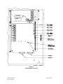
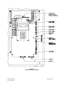
Mounting........................................................................................................................................………..…………………
…..
Grounding.......................................................................................................................................…………………………..
....
Field
Wiring.....................................................................................................................................……………………………...
Field Wiring
Checkout.......................................................................................................................…………………………....
System
Checkout..............................................................................................................................……………………….…...
Ground Fault Detection Sensitivity
Adjustment...................................................................................……...……………….....
Installation and Care of Sealed Lead Acid
Batteries................................................................................……...……………….
Configuration................................................................................................................................………....…………………
....
Power
Calculations...............................................................................................................................……………………….….....
Standby Current
Calculations..........................................................................................................……......…………………...
Alarm Current
Calculations...............................................................................................................………..…………………..
Battery Capacity
Calculations..........................................................................…….......................................…………………..
Sample
Calculation.............................................................……………..............................................………..………………....
Page
8
25
26
26
26
28
42
42
43
44
44
45
45
45
46
46
Sheet 7 of 78
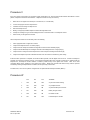
Troubleshooting....................................................................................................................................……….…………………
.....
Procedures A, B, C,
D.....................................................................................................................………...…………………...
Procedures E, F, G,
H......................................................................................................................………...…………………..
Procedure I, J, K,
L..........................................................................................................................……….…………………....
Procedure M, N
,O...........................................................................................................................………..…………………...
Procedure P,
Q.................................................................................................................................……….…………………...
Procedure R,
S.................................................................................................................................…………………………....
Procedure T,
U................................................................................................................................……….…………………....
Procedure V, W, X, Y,
Z....................................................................................................................……….…………………...
47
51
52
53
54
55
56
57
58
Periodic
Testing................................................................................................................................……….…………………….....
59
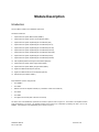
Module
Description..............................................................................................................................……..…………………….....
Introduction..................................................................................................................................…………………………….
.....
Supervised Audio System Mother Board (SAMBA).................................................................................……………………...
Supervised Audio System Common Control Module
(SADC)......................................................................…………………...
Supervised Audio System Amplifier/Signal Circuit Module, 40 Watts
(SAA).............................................……..……………...
Self Amplified Speaker Control/Signal Circuit Module (SACM4).........................................................……......……………....
Supervised Audio System Power Supply Module
(SAPS)..........................................................................…….……………...
Supervised Audio System Battery Charger Module
(SABC)...............................................................…….........……………...
Digital Voice Module with Playback (DX100).....................................................................................……...………………......
Digital Voice Module with Record and Playback (DX200)..................................................................…………………............
60
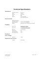
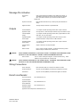
Technical
Specifications........................................................................................................................………………………….....
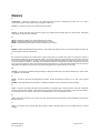
Glossary.............................................................................................................................................………...…………………
…..
Limited
Warranty....................................................................................................................................…………………………....
Limitation of
Liability............................................................................................................................………………………….......
Appendix A. Standard Protocol Description (RS232).................................................................................…………………….....
Appendix B. Standard Protocol Description (RS485)...........................................................................…….......………………....
Appendix C. Display and Keypad
Operation..........................................................................................……….………………......
Appendix D.
........................................................................................................................................………………………….....
Appendix E. Compatible Signaling
Devices..............................................................................................………………………....
Appendix F. Remote
SAFEPATH...........................................................................................................………....………………..
SAFEPATH Manual
Rev. C April 1999
60
63
64
66
68
70
71
72
73
75
77
78
78
A-1
B-1
C-1
Reserved
E-1
F-1
Sheet 8 of 78
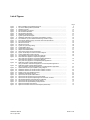
List of Figures
Figure
Figure
Figure
Figure
Figure
Figure
Figure
Figure
Figure
Figure
Figure
Figure
Figure
Figure
Figure
Figure
Figure
Figure
Figure
Figure
Figure
Figure
Figure
1
2
3
4
5
6
7
8
9
10
11
12
13
14
15
16
17
18
19
20
21
22
23
Figure
24
Figure
25
Figure
26
Figure
Figure
Figure
Figure
Figure
Figure
Figure
Figure
Figure
Figure
Figure
Figure
Figure
27
28
29
30
31
32
33
34
35
36
37
38
39
Basic Capabilities of the SAFEPATH Panel.......................................….................….…….......
Top View of Message Memory EPROM...................................................…………..................
Operator's Console...........................................................................................……………......
File Downloading Connection..........................................................................…………...........
DX-100 Module Illustration.............................................................................…………….........
DX-200 Module Illustration...................................................................................……………...
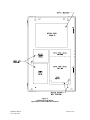
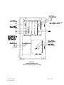
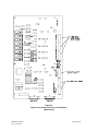
SAFEPATH Panel Mounting.................................................................................…………......
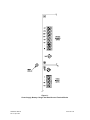
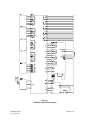
Typical System Block Diagram...............................................................................…………….
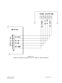
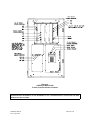
SAFEPATH Field Wiring Input/Output Terminal Block Locations...............................……….....
Terminal Block Layout for SAFEPATH Message Activation Inputs...............................………..
Power Supply, Battery Charger, and Earth Ground Terminal Blocks............................………..
Dry Contact Input Wiring....................................................................................……………....
RS-232 Port Pin Out............................................................................................……………...
RS-485 Port Pin Out.........................................................................................……………......
Typical AC Input Voltage Wiring............................................................................……………..
Typical Battery Wiring...........................................................................................……………..
Typical Earth Ground Wiring..............................................................................…………….....
Output Terminal Block Detail................................................................................…………......
Alarm Output Contact Connection Diagram.........................................................…………......
System Trouble Output Contact Connection Diagram..............................................……….....
Trouble Audible Output Wiring Diagram................................................................………….....
Visual Notification Appliance Output Wiring Diagram..........................................………….......
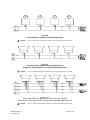
Audio Notification Appliance Output Wiring Diagram
Using Audio Only Appliances in Central Amplified Applications...............................………......
Audio Notification Appliance Output Wiring Diagram
Using Audio Only Appliances in Amplified Speaker Applications...........................……….........
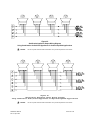
Notification Appliance Output Wiring Diagram
Using Combination Audio/Visual Appliances in Central Amplified Applications........……..…....
Notification Appliance Output Wiring Diagram
Using Combination Audio/Visual Appliances in Amplified Speaker Applications.......………......
Optional Remote Microphone (RMS-1) Wiring Diagram..........................................……….......
SAFEPATH with DX-100 Trouble Location Indicator Locations.................................……….....
SAFEPATH with DX-200 Trouble Location Indicator Locations...................................………...
Module Layout of the SAFEPATH Panel.................................................................…………...
SAFEPATH Panel Block Diagram.............………................................................………..........
Supervised Audio System Mother Board...................................................................………….
Supervised Audio System Common Control Module..................................................………....
Supervised Audio System Amplifier/Signal Circuit Module, 40 Watts..........................………...
Self Amplified Speaker Control/Signal Circuit Module............................................………….....
Supervised Audio System Power Supply Module...............................................…………........
Supervised Audio System Battery Charger Module................................................…………....
Digital Voice Module with Playback......................................................................……………...
Digital Voice Module with Record and Playback (Main Board)..................................……….....
SAFEPATH Manual
Rev. C April 1999
Page
9
10
18
21
23
24
27
31
32
33
34
35
35
36
36
36
37
37
38
38
38
39
39
39
40
40
41
49
50
61
62
63
65
67
69
70
71
72
74
Sheet 9 of 78
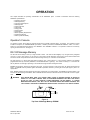
Introduction
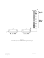
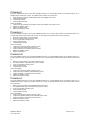
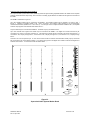
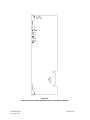
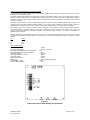
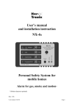
SAFEPATH is a stand alone voice evacuation/emergency message panel capable of providing up to four zones of audible and
visual signals. Figure 1 illustrates the basic capabilities of the SAFEPATH panel.
The SAFEPATH panel can play back recorded voice, tones, and other sounds when instructed to do so by contact closure or an
instruction over a serial link from other equipment. SAFEPATH panels configured with a DX-100 are playback only panels.
SAFEPATH panels configured with a DX-200 can also record the messages.
This manual describes the SAFEPATH panel, which features:
•
A multitone generator with 8 field selectable sounds for the primary evacuation signal.
•
Up to 8 minutes of audio storage in DX-100 configured panels.
•
Up to 16 minutes of audio storage in DX-200 configured panels.
•
Selective activation of up to 8 message files using contact closures (expandable to 256 message files using optional Digital
Voice Expansion Modules (DV-EM's).
•
Selective activation of up to 999 message files through the serial port (RS-232 or RS-485).
•
Field upgradable.
•
Up to 5 levels of message priority assignments with the two least significant priority levels being acknowledgeable.
•
Up to four audio and strobe circuits, zone selectable.
•
Supervision of input and output lines and many internal operations with trouble diagnosis and notification.
•
Serial communication supervision and optional verification of serial commands with a trouble indication if an error is detected.
•
Manual override of automatically playing files with live announcements.
•
An optional telephone interface.
•
An RS-232 interface and an optional RS-485 interface.
•
An optional Remote Microphone (RMS-1).
THE SAFEPATH PANEL MUST BE PROPERLY INSTALLED, PROGRAMMED AND CONNECTED TO A COMPATIBLE
CONTROL PANEL TO FUNCTION IN A VOICE EVACUATION SYSTEM.
The control panel which activates the SAFEPATH panel can range from simple push-buttons or detectors that provide contact
closures to activate SAFEPATH files to a sophisticated, computer-based control panel that activates SAFEPATH files through a
serial port.
WARNING:
SAFEPATH Manual
Rev. C April 1999
THE OPTIONAL TELEPHONE INTERFACE SHALL NOT BE USED FOR PRIMARY NOTIFICATION OF AN
EMERGENCY SITUATION, EVENT, ACTION OR CAUSE.
Sheet 10 of 78
Figure 1.
Basic Capabilities of the SAFEPATH Panel
SAFEPATH Manual
Rev. C April 1999
Sheet 11 of 78
OPERATION
This chapter describes the operating characteristics of the SAFEPATH panel.
SAFEPATH panel features:
•
•
•
•
•
•
•
•
•
•
•
•
Included is information about the following
Operator's Console
Message Memory
Input and Output Options
Message Files
Output Channels
File Priority
Playing Files
System Pause
Supervision
Back-up Battery Requirements
Password Protection
Memory Retention Battery
Operator's Console
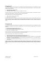
An operator's console, which allows for manual override of the automatic message playing, is provided. The operator's console
includes a microphone, an "ACKNOWLEDGE" push-button, “RESET” push-button, a "MANUAL/AUTOMATIC " switch, “ALL-CALL”
switch, four zone disarrangement switches, and "NORMAL" and "TROUBLE" indicators. The operator's console is accessed by
opening the enclosure door. See Figure 3.
DX-100 Message Memory
The DX-100 has the ability to store up to eight minutes of audio. The audio is stored digitally on up to eight memory integrated
circuit ("I.C.") chips. Each memory I.C. can store up to one minute of audio messages. See Figure 5 for the socket locations S63
and S70 on the DX-100 printed circuit board into which the eight memory I.C.'s U63 thru U70 are inserted.
The eight memory I.C.'s which store audio data are U63 thru U70. These memory I.C.'s are commonly referred to as erasable
programmable read only memories ("EPROM's", see EPROM definition in glossary). The number of memory I.C.'s in the DX-100
will vary between one and eight, depending on the number and length of audio messages recorded.
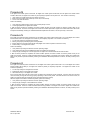
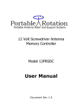
EPROM's are erased by exposure to ultraviolet ("UV") light. UV light is present in light sources such as sunlight and fluorescent
lamps. An EPROM must be protected against accidental or premature erasure by covering its window (see Figure 2) with a UV
opaque label.
Each EPROM supplied with this module has its window covered with a UV opaque label. An EPROM's UV opaque label is to be
removed only when erasing the EPROM. After an EPROM has been erased, its window must be recovered with a new UV opaque
label.
WARNING:
EACH EPROM MUST HAVE A UV OPAQUE LABEL PLACED IN PROPER POSITION AS SHOWN IN
FIGURE 2. IF THE LABEL IS WORN, TORN, OR OTHERWISE DAMAGED IN ANY WAY THAT WOULD
ALLOW UV LIGHT TO PASS THROUGH, STORED MESSAGES CAN BE ERASED. IF STORED
MESSAGES ARE ERASED, THEY WILL NOT BE DELIVERED WHEN AND WHERE REQUIRED, AND
COULD RESULT IN PROPERTY DAMAGE AND SERIOUS INJURY OR DEATH TO YOU AND/OR OTHERS.
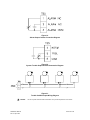
Figure 2.
Top View of Message Memory EPROM
SAFEPATH Manual
Rev. C April 1999
Sheet 12 of 78
DX-200 Message Memory
The DX-200 has the ability to store up to sixteen minutes of audio. The audio is stored digitally on up to eight memory I.C.'s. Each
memory I.C. can store up to two minutes of audio messages. See Figure 6 for the socket locations S63 thru S70 on the DX-200
printed circuit board into which the eight memory I.C.'s, U63 thru U70, are inserted.
These memory I.C.'s are commonly referred to as pseudo static random access memories ("PSRAM's", see PSRAM definition in
glossary). If the input power is disconnected and the memory retention battery is or has been disconnected or discharged, the
PSRAM I.C.'s will be erased.
WARNING:
IF BOTH THE INPUT POWER AND THE BATTERY BACK-UP POWER ARE DISCONNECTED AND THE
MEMORY RETENTION BATTERY IS OR HAS BEEN DISCONNECTED OR DISCHARGED, ALL MESSAGES
IN THE PSRAM I.C.'S WILL BE ERASED. IF STORED MESSAGES ARE ERASED, THEY WILL NOT BE
DELIVERED WHEN INPUT POWER IS RESTORED. THIS COULD RESULT IN PROPERTY DAMAGE AND
SERIOUS INJURY OR DEATH TO YOU AND/OR OTHERS.
Input and Output Options
Each SAFEPATH panel model includes 8 inputs that can be used to activate file numbers 1 through 8 with a contact closure or a
transistor switch across the corresponding input terminals. The optional digital voice expansion modules ("DV-EM") can provide 32
inputs. When a DV-EM is used, the 8 inputs in the SAFEPATH panel cannot be used. Up to 8 DV-EM’s can be connected to a
SAFEPATH panel for a total of 256 inputs.
Make sure that SAFEPATH audio outputs are connected to properly operating, listed compatible notification appliances so that
message files assigned to that channel can be played.
The SAFEPATH panel is provided with a serial port, through which up to 999 files can be activated with digital commands. The
contact inputs in the SAFEPATH panel or DV-EM's can be used along with the serial port. A command is required to start a
message, and a second command is required to stop the message. The operation is similar to closing an input contact (start) and
then reopening the contact (stop).
Up to four audio output channels are available with the SAFEPATH panel. The output from each audio channel may be either a 15
Ohm line level output or a 25V or 70.7V amplifier output. The 15 Ohm line level output can drive up to forty 600 Ohm line level input
appliances. The 25V or 70.7V amplifier can drive up to 40 Watts of speaker notification appliances.
Message Files
All messages are stored in files within the digital voice module’s message memory. Up to 999 message files can be stored. There
is no limit on the length of a message file (except for the limit imposed by total memory in the unit). There are two types of message
files: voice files and string files. Voice files are created by storing audio directly into the selected file number. String files are
created by storing file numbers of other message files into the selected file number. (See "file" and "string" definitions in glossary.)
Each message file must be assigned a priority level from 1 to 5 (1 is highest, 5 is lowest) and an output channel from 1 to 4. See
“Output Channels”, “File Priority”, and “Playing Files” sections for additional information.
WARNING:
EACH MESSAGE MUST BE ASSIGNED ITS INTENDED OUTPUT CHANNEL AND PRIORITY LEVEL
DURING PROGRAMMING OR THE MESSAGE WILL NOT BE PLAYED WHEN AND WHERE REQUIRED.
THIS COULD RESULT IN PROPERTY DAMAGE AND SERIOUS INJURY OR DEATH TO YOU AND/OR
OTHERS.
String files reduce the message memory requirements by allowing many different message files to be created with a relatively small
library of voice files that contain custom words or phrases and using one or more of the six string file commands. The string file
commands are ADD, PAUSE, COMMON REPEAT, FILE REPEAT, TELEPHONE, and END. ADD is used to add a previously
created message file to the string. PAUSE is used to add a period of silence to the string. COMMON REPEAT is used to play the
next entered file number multiple times. FILE REPEAT is used to play the entire file again a specified number of times after the file
has been de-activated. TELEPHONE is used to add telephone numbers to a string file. END is used to finalize the string.
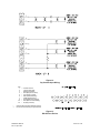
The following is an example of creating string files from a small library of voice files using the ADD command.
The following voice messages are recorded into the indicated file numbers:
“There is a fire on the”
into file number 100
“First”
into file number 101
“Second”
into file number 102
“Third”
into file number 103
“Floor”
into file number 104
Create three string files as indicated:
File 1:
ADD 100, ADD 101, ADD 104, END
File 2:
ADD 100, ADD 102, ADD 104, END
File 3:
ADD 100, ADD 103, ADD 104, END
When file number 1 is selected to play, “There is a fire on the first floor” will be played. When file number 2 is selected to play,
“There is a fire on the second floor” will be played. When file number 3 is selected to play, “There is a fire on the third floor” will be
played.
SAFEPATH Manual
Rev. C April 1999
Sheet 13 of 78
The following is an example of creating string files using the ADD command and the PAUSE command.
The following voice messages are recorded into the indicated file numbers:
“Welcome to Herbie’s”
into file number 100
“Our fish are the freshest in town”
into file number 101
Create a string file as follows:
File 1:
ADD 100, PAUSE 10 seconds, ADD 101, END
When file number 1 is selected to play, “Welcome to Herbie’s”......(10 seconds of silence)......”Our fish are the freshest in town” will
be played.
The following is an example of creating string files using the ADD command and the COMMON REPEAT command.
The following voice messages are recorded into the indicated file numbers:
“Run”
into file number 100
“to the nearest salesman” into file number 101
Create a string file as follows:
File 1:
COMMON REPEAT 3 times, file number 100, ADD 101, END
When file number 1 is selected to play, “Run, Run, Run to the nearest salesman” will be played.
The following is an example of creating string files using the ADD command and the FILE REPEAT command.
The following voice message is recorded into the indicated file number:
“Thank you for buying Wheelock voice products”
into file number 100
Create a string file as follows:
File 1:
ADD 100, FILE REPEAT 3 times
When file number 1 is selected to play, “Thank you for buying Wheelock voice products” will be played. The file will play
continuously as long as the file is activated. After the file is de-activated, the file will play three additional times. A momentary
activation will play the message four times. The FILE REPEAT command must be the last item in the string.
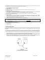
The following is an example of creating string files using the ADD command and the TELEPHONE command.
The following voice message is recorded into the indicated file number:
“A fire has been detected at 101 Main Street”
into file number 100
Create a string file as follows:
File 1:
TELEPHONE 555-0100, TELEPHONE 555-1212
TELEPHONE 555-4949, ADD 100, END
When file number 1 is selected to play, the phone number 555-0100 is called. If the line is busy or the call is unanswered, the
phone number will be tried two more times. After the third attempt, the next number in the string file is called. If three attempts to
that number fail, the next number in the string file is called, and so on. If the last phone number in the string file also fails three
times, the process starts over with the first phone number.
If at any point the called phone number is answered, the message “A fire has been detected at 101 Main Street” is played. Within
30 seconds of the end of the message, the digital voice module expects to hear an acknowledge code from the person receiving the
message. If the acknowledge code is not received, the digital voice module treats the call the same as a line busy or an
unanswered call. The acknowledge code expected is a “1-2-3” dialed from a touch-tone phone. When the acknowledge code is
received, the digital voice terminates the file, and no other calls are made.
The TELEPHONE command is only available to use in string files programmed for channel 1 with no secondary channels.
TELEPHONE commands must be the first commands entered into the string. Once any other command has been selected when
creating a string file, the TELEPHONE command is prohibited from being used.
Output Channels
The SAFEPATH panel may be configured with between one and four output channels. Installed output channels are labeled
consecutively 1 to 4, as necessary. Message files may be programmed to play out any combination of the four output channels.
When a message file is programmed to play out multiple output channels, the message will not necessarily play simultaneously on
all selected output channels.
SAFEPATH Manual
Rev. C April 1999
Sheet 14 of 78
File Priority
The priority of a file playing on one channel will not affect the priority of files playing on any other channel. Priority levels are 1 thru
5, 1 being highest, 5 being lowest.
Priority 1 and Priority 2 files WILL interrupt any file with a lower priority that is playing through the same output channel. Priority 3
and Priority 4 files will NOT interrupt lower priority files but will begin playing immediately upon completion of any lower priority file.
Any file that is interrupted by a higher priority file before it has completed playing will remain on the channel queue until it is allowed
to replay completely.
If two files or more of equal priority are activated, the files will play sequentially as long as the files are activated.
Priority 4 and Priority 5 files may be acknowledged. Files are acknowledged by the reception of an acknowledge command on the
serial port or activation of the acknowledge input. Acknowledged files will play one more time and then be removed from the queue.
Dry contact activated files must have their input released and then reactivated to play again. Serial command activated files must
have another serial start command transmitted to play again.
Files of all priority levels may be reset. Files are reset by the reception of a reset command on the serial port or activation of the
reset input. Reset files will stop immediately and are removed from the queue. Dry contact activated files must have their input
released and then reactivated to play again. Serial command activated files must have another serial start command transmitted to
play again.
Note:
In the United States the latest NFPA guidelines and standards provide that life safety/fire notification alarm tone(s) and
voice message(s) are the only alarm tone(s) and message(s) that shall be assigned priority 1 for all SAFEPATH panel
output channel(s) assigned to either a dedicated life safety/fire alarm protective signaling system or the life safety/fire
alarm system portion of an integrated multi-function system.
Acknowledge Playing Files
All priority 4 and priority 5 files may be acknowledged. Files activated by a dry contact input may be acknowledged by activating the
acknowledge dry contact input. Files activated by a serial command may be acknowledged by the serial acknowledge command.
Files which have been acknowledged will play one more time and then be removed from the queue. String files which have been
programmed with a file repeat will play the number of times selected by the file repeat option and then be removed from the queue.
Dry contact activated files which have been acknowledged must have their input released and then reactivated to play again. Serial
command activated files which have been acknowledged must have another serial start command transmitted to play again.
Any dry contact input may be selected to be the acknowledge input. An input selected to be the acknowledge input may not be used
to activate files to play. The acknowledge input feature may be disabled by selecting input 0 to be the acknowledge input. In
SAFEPATH panels configured with a DX-200 the acknowledge input selection is located in the SETUP procedure from the main
menu on the DX-200. In SAFEPATH panels configured with a DX-100, the acknowledge input is selected by first selecting the
required input on a Series DV-200 and then transferring the Series DV-200’s configuration.
Reset Playing Files
Files of all priority levels may be reset. Files activated by a dry contact input may be reset by activating the reset dry contact input.
Files activated by a serial command may be reset by the serial reset command. Files which have been reset will stop playing
immediately and be removed from the queue. Dry contact activated files which have been reset must have their input released and
then reactivated to play again. Serial command activated files which have been reset must have another serial start command
transmitted to play again.
Any dry contact input may be selected to be the reset input An input selected to be the reset input may not be used to activate files
to play or to be the acknowledge input. The reset input feature may be disabled by selecting input 0 to be the reset input. In
SAFEPATH panels configured with a DX-200, the reset input selection is located in the SETUP procedure from the main menu on
the DX-200. In the SAFEPATH panels configured with a DX-100, the reset input is selected by first selecting the required input on a
Series DV-200 and then transferring the Series DV-200’s configuration.
Note:
The reset switch must be located within a locked enclosure.
Playing Files
The digital voice module stores message file activations in a separate queue (see "queue" definition in glossary) for each output
channel. Files can be added to the queue by a contact activation or a serial port start command. Files in each queue are played in
the order of file priority. Equal priority files are played in the order of activation.
When a contact activation is detected, the programmed message file is placed on the programmed queue. The contact input is then
not checked for activation again until the message file completes playing. Therefore, a momentary contact closure will only play a
message file once and a maintained contact closure will continuously repeat a message file as long as its input is held activated
(unless it is interrupted by a higher priority file, played alternately with other equal priority files, acknowledged, or reset). (See
"acknowledge" definition in Glossary.)
When a valid serial port start command is received, the programmed message file is placed on the programmed queue. Each time
the file completes playing, the digital voice module checks to see if a valid serial port stop command has been received. If one has
been received, the message file is removed from the queue. As long as the file is on the queue, it will repeat continuously (unless it
is interrupted by a higher priority file, played alternately with other equal priority files, acknowledged, or reset).
SAFEPATH Manual
Rev. C April 1999
Sheet 15 of 78
System Pause
The ability to have a pause between messages is provided. Having a pause between all playing messages prevents messages
from “running together” and then being misunderstood. The system pause may be any value from 1 to 999 seconds. The system
pause is programmed directly into SAFEPATH panels configured with a DX-200. In SAFEPATH panels configured with a DX-100,
the system pause is programmed by first setting the required value on a Series DV-200 and then transferring the Series DV-200’s
configuration.
Supervision
A trouble condition indicates that the supervision functions have detected a malfunction in the SAFEPATH panel. When a trouble
condition is detected, the SAFEPATH panel may not be able to receive and/or remember message requests from the control panel.
The installer and/or user must make sure that any message requests to the SAFEPATH panel during a trouble condition are
reactivated if necessary, when the SAFEPATH panel returns to normal.
If a trouble condition is detected by any of the supervision functions, the SAFEPATH panel Form C status relay (normally
energized) will change state, the green system normal LED will turn off, and the amber trouble LED will turn on. The status relay
contact closure must be properly connected to and used by the control panel to indicate a system trouble. At the same time an
amber trouble location LED will identify the location of the trouble condition. If a trouble condition is indicated, follow the procedures
in the "Troubleshooting and Servicing" section.
WARNING:
DO NOT LEAVE THE SAFEPATH PANEL IN A TROUBLE CONDITION AS, IT MAY NOT PLAY WARNING
MESSAGES WHICH COULD RESULT IN PROPERTY DAMAGE AND SERIOUS INJURY OR DEATH TO
YOU AND/OR OTHERS. IF SAFEPATH INDICATES A TROUBLE CONDITION: (1) PROVIDE UL REQUIRED
ALTERNATIVE SIGNALING AND (2) HAVE QUALIFIED SERVICE PERSONS IMMEDIATELY REPLACE
UNIT(S) THAT HAVE MALFUNCTIONED.
WARNING:
MESSAGES REQUESTED BEFORE AND DURING A TROUBLE CONDITION MAY NOT BE HEARD, WHICH
COULD RESULT IN PROPERTY DAMAGE AND SERIOUS INJURY OR DEATH TO YOU AND/OR OTHERS.
IF MESSAGES REQUESTED BEFORE AND DURING A TROUBLE CONDITION ARE STILL NECESSARY,
THEY SHOULD BE REPEATED WHEN THE SAFEPATH PANEL IS RETURNED TO NORMAL.
Input Voltage Supervision
Input voltage is supervised, and if the input voltage drops below the operating minimum voltage, the SAFEPATH panel will transfer
to battery back-up power and indicate a trouble condition.
Program Memory Supervision
The digital voice module’s program memory is supervised using a sumcheck technique to detect any changes in the stored data. If
a change is detected, the digital voice module will stop operating and the SAFEPATH panel will indicate a trouble condition.
Message Memory Supervision
The digital voice module’s message memory is supervised using a sumcheck technique to detect any changes in the stored data. If
a change is detected, the digital voice module will stop operating and the SAFEPATH panel will indicate a trouble condition.
Microprocessor Supervision
Each microprocessor within the SAFEPATH panel has a watchdog circuit that supervises the processor and resets it (if necessary)
or maintains a trouble condition if the microprocessor cannot be restarted. Each watchdog circuit constantly monitors the
functioning of its microprocessor and, if the microprocessor fails to function properly, will attempt to reset and restart the
microprocessor.
Expansion Module Supervision
If there are any DV-EM’s connected to the SAFEPATH panel, the SAFEPATH panel will automatically detect their presence. It will
then monitor these expansion modules. Thereafter, if any expansion module is disconnected, the SAFEPATH panel will indicate a
trouble condition.
Input Line Supervision
All input lines (for contact closure or transistor activation) are supervised for open circuits and ground faults. Input line supervision
requires a LISTED 10K end-of-line resistor to be installed on each input including all unused and unsupervised inputs. Internal
digital voice module circuitry is also supervised
To comply with NFPA requirements for interconnection of fire alarm control equipment, the SAFEPATH panel must be located in the
same room as, and within 20 feet of, a listed compatible fire alarm control panel with the wiring enclosed in conduit and properly
connected to such panel.
WARNING:
SAFEPATH Manual
Rev. C April 1999
THE INPUT LINE SUPERVISION DETECTS ONLY OPEN CIRCUITS AND GROUND FAULTS. IF THE
INPUT LINE SUPERVISION IS NOT INSTALLED AS INDICATED, THE SAFEPATH PANEL WILL BE
UNABLE TO DETECT OPEN CIRCUITS AND GROUND FAULTS ON THE INPUT LINE WHICH COULD
RESULT IN PROPERTY DAMAGE AND SERIOUS INJURY OR DEATH TO YOU AND/OR OTHERS.
Sheet 16 of 78
Visual Notification Appliance Output Line Supervision
All visual notification appliance output lines are supervised. The lines are supervised for open circuits, short circuits, and ground faults when
the output is de-energized; and ground faults only when the output is energized. Output line supervision requires a LISTED 10K end-of-line
resistor to be installed on each output circuit and across the terminals of unused output circuits.
Audio Notification Appliance Output Line Supervision
All audio notification appliance output lines are supervised. The lines are supervised for open circuits, short circuits, and ground faults when
the output is de-energized. The lines are unsupervised when the output is energized. Output line supervision requires a LISTED 10K endof-line resistor to be installed on each output circuit and across the terminals of unused output circuits.
Amplified Speaker Notification Appliance Power Output Line Supervision
All amplified speaker notification appliance power output lines are supervised. The lines are supervised for open circuits, short circuits, and
ground faults when the output is de-energized, and ground faults only when the output is energized. Output line supervision requires a
LISTED 10K end-of-line resistor to be installed on each output circuit and across the terminals of unused output circuits.
Digital Voice Module Audio Supervision
The audio circuitry of each digital voice module output channel is supervised up to the secondary coil of the output transformer. When a
message is playing, a trouble condition is indicated if an audio signal is not detected for more than 3 seconds or a low impedance load (less
than 600 ohm) is connected to the line output. An audio signal not detected or low impedance load detected trouble condition will clear
automatically as soon as audio is detected or the low impedance load is no longer detected, respectively. When no messages are playing,
the circuitry is continuously supervised for functionality. If a circuitry failed condition is detected, the SAFEPATH panel will indicate a trouble
condition.
Serial Port Supervision
The SAFEPATH panel can receive commands over a serial port. The standard protocol used on the serial port is described in
Appendix A. If a second, optional protocol is provided on the serial port, it is described in Appendix B.
The serial port is supervised for communication errors and ground faults. A trouble condition will be indicated if a communication error is
detected, the SAFEPATH panel does not select a file, or the received command is not understood. The trouble condition will return to
normal with the next valid command received. See Appendix A (and B, if applicable) for additional serial port information.
The SAFEPATH panel also provides a response for each command received through the serial port. If so programmed, the control panel
can supervise the serial port by receiving and comparing the response of each transmitted command. The control panel can both verify the
integrity of the physical connection of the serial communication line and the integrity of the commands received by the SAFEPATH panel.
CAUTION:
External wiring to/from the serial port of the SAFEPATH panel is not supervised by the SAFEPATH panel.
Wheelock strongly recommends that the control panel be programmed to use the SAFEPATH panel's serial
response capability (described in Appendix A or B, if applicable) to verify the integrity of the serial
communications link and to record any communication errors for corrective action.
Ground Fault Supervision
The SAFEPATH panel has the ability to supervise for ground fault conditions on field wiring that is not electrically isolated. The supervised
wiring includes contact inputs and serial port wiring. All other wiring is electrically isolated. Ground fault supervision may be enabled and
disabled by placing the "GROUND FAULT ENABLE/DISABLE" jumper (JP2) on the digital voice module in the desired position. See Figures
5 and 6, respectively, for the location of the jumper (JP2) on the DX-100 and DX-200 printed circuit board within the SAFEPATH panel.
Memory Retention Battery Supervision
The DX-200’s digital voice module’s memory retention battery is supervised for correct placement and functionality. The battery is not
supervised for level of charge. The battery is checked by the circuitry once every 5 minutes.
Battery Back-Up Line Supervision
The battery back-up lines are supervised for open circuits, short circuits and ground faults.
Back-Up Battery Supervision
The back-up battery is supervised for low voltage conditions.
Telephone Line Supervision
When a telephone string file is selected to play out channel 1 of the digital voice module (DX-100 or DX-200), channel 1’s line out is
supervised for connection to a telephone line. The telephone line is supervised by monitoring the telephone line’s DC voltage and by
detecting the proper call progress tones. If either of these two parameters are not correct, the SAFEPATH panel will indicate a trouble
condition.
Telephone string files are also supervised for correct reception by the intended party. If three consecutive call attempts to the same phone
number go unanswered and/or unacknowledged, the SAFEPATH panel will indicate a trouble condition.
When channel 1 of the digital voice module is connected to a telephone line, it may not be used to play messages through an amplifier
module.
Remote Microphone Supervision
The optional remote microphone is supervised for proper operation and for open circuits, short circuits and ground faults.
SAFEPATH Manual
Rev. C April 1999
Sheet 17 of 78
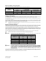
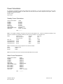
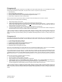
Back-Up Battery Requirements
Table 1 below shows the amp-hour of battery Back-Up required for various system configurations.
BACK-UP BATTERY REQUIREMENTS
CAPACITY OF BACK-UP BATTERY REQUIRED
(IN AMP HOURS)
4 HOURS
24 HOURS STANDBY
60 HOURS STANDBY
STANDBY
15 MINUTES ALARM
15 MINUTES ALARM
24AH
48AH
(Future)
24AH
48AH
(Future)
24AH
72AH
(Future)
24AH
72AH
(Future)
NUMBER
OF AMPLIFIER
MODULES INSTALLED
1
2
3
4
Table 1.
Password Protection
The SAFEPATH panel configured with a DX-200 incorporates password protection to prevent unauthorized use of the keypad on the DX200. Passwords may be any number from 0 to 999. The password must be entered correctly to access any system functions.
The initial password is 111. It is strongly recommended that this password be changed. Instructions for changing passwords are given in
the "Setup" section of Appendix C.
Once the password is entered correctly, the user has access to all system functions. If at any time the user has accessed a system
function, but failed to utilize it for at least five minutes, the accessed system function will cease and the enter password screen will be
displayed. The password then must be re-entered and the system function reaccessed.
Note:
The password should only be given to authorized and properly trained personnel who are responsible for the operation, testing,
and maintenance of the SAFEPATH panel.
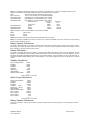
Memory Retention Battery
SAFEPATH panels configured with a DX-200 contain a memory retention battery to power the DX-200 PSRAM message memory during
periods when both input power and battery back-up power have been disconnected from the SAFEPATH panel. The battery's only function
is to prevent the message files stored in the PSRAM I.C.'s from being lost. The memory retention battery powers no other circuitry.
The DX-200 contains battery charging circuitry to maintain the battery at full charge. The charging circuitry has two charging rates, fast
charge and trickle charge. The fast charge cycle is initiated whenever input power is first connected to the digital voice module and lasts for
24 hours. After 24 hours the fast charge cycle is terminated and the trickle charge cycle is initiated and will remain on as long as input
power or battery back-up power remain connected to the SAFEPATH panel.
The memory retention battery duration times for new fully charged batteries during periods of power loss, is shown in Table 2 below.
Note:
The memory retention battery in the SAFEPATH panel is shipped in a completely discharged state.
CAUTION:
As batteries age, they lose their ability to charge completely. The memory retention battery should be replaced at least
once per year to ensure optimum battery performance.
MEMORY RETENTION BATTERY BACKUP DURATION
FOR NEW FULLY CHARGED BATTERIES DURING PERIODS OF POWER LOSS
NUMBER OF
MINIMUM
TYPICAL
MEMORY I.C.'S
(HRS)
(HRS)
1
3000
6000
2
1500
3000
3
1000
2000
4
750
1500
5
600
1200
6
500
1000
7
428
857
8
375
750
Table 2.
WARNING:
IF THE INPUT POWER AND THE BATTERY BACK-UP POWER ARE DISCONNECTED AND THE MEMORY
RETENTION BATTERY IS OR HAS BEEN DISCONNECTED OR DISCHARGED, ALL MESSAGES IN THE PSRAM
I.C.'S WILL BE ERASED. IF STORED MESSAGES ARE ERASED, THEY WILL NOT BE DELIVERED WHEN INPUT
POWER IS RESTORED. THIS COULD RESULT IN PROPERTY DAMAGE AND SERIOUS INJURY OR DEATH TO
YOU AND/OR OTHERS.
If for any reason the input power and the battery back-up power are disconnected and the memory retention battery is or has been
disconnected or discharged and all messages in the PSRAM I.C.'s are erased, all messages will have to be reprogrammed into the
SAFEPATH panel once the input power or the battery back-up power is reconnected.
SAFEPATH Manual
Rev. C April 1999
Sheet 18 of 78
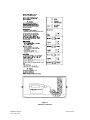
Operator Instructions
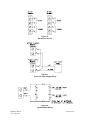
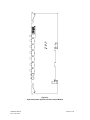
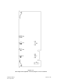
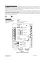
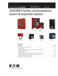
The SAFEPATH panel provides an operator console for manually activating the panel. The operator console includes a
microphone, a green “NORMAL” indicator, a yellow “TROUBLE” indicator, an “ACKNOWLEDGE” push-button switch, a “RESET”
push-button, a “MANUAL/AUTOMATIC” switch, an “ALL-CALL” switch and four “ZONE SELECT” switches. The operator interface
allows the operator to manually override automatically playing pre-recorded messages with live announcements or an evacuation
tone, to silence internal and external trouble audibles, and to ascertain if the panel has detected a trouble condition. The operator
interface is shown in Figure 3.
The “TROUBLE” and “NORMAL” indicators are visible through a window on the panel door, when door is closed. All other operator
controls are only accessible by opening the panel door.
The “SELECT” LED’s indicate the zones selected for live announcements.
The ”ALARM” LED’s indicate the zones actively in alarm.
The two indicators identify to the operator when the SAFEPATH panel has detected a trouble condition. The yellow “TROUBLE”
indicator will be illuminated whenever there is a trouble detected by the SAFEPATH panel. If no troubles are detected, the green
“NORMAL” indicator will be illuminated.
The “ACKNOWLEDGE” push-button allows the operator to silence the trouble audibles, both internal and external. When a trouble
condition is detected, both the internal and external trouble audibles are sounded. When the “ACKNOWLEDGE” push-button is
depressed, the internal and external trouble audibles will be silenced. The trouble audibles will resound for subsequent trouble
conditions. The Form C trouble output contact will remain in the trouble condition and the “TROUBLE” indicator will remain
illuminated until all trouble conditions have been corrected.
The “RESET” push-button resets the strobe circuits after all initiating circuits are reset.
The “MANUAL/AUTOMATIC” switch has two positions, manual (down) and automatic (up). When the “MANUAL/AUTOMATIC”
toggle switch is in the automatic position, pre-recorded messages may be selected to play in individual circuits via dry contact inputs
and/or a serial communication interface. When the “MANUAL/AUTOMATIC” switch is in the manual position, pre-recorded
messages will not play, and the visual notification appliances are energized and the evacuation tone sounds in all circuits.
The “ALL-CALL” switch overrides any zone selection and allows audible signals to be heard regardless of the position of the four
zone select switches.
The four “ZONE SELECT” switches are numbered 1 through 4. They are used to silence any audible signal and turn off visual
signals in the respective zones, for live announcements only.
Operation Instructions
To make a live announcement:
1. Select specific zones or use “ALL-CALL” as necessary.
2. Remove microphone from its holder.
3. Hold down microphone’s push-to-talk button and talk into microphone.
To manually sound evacuation tone:
1. Move “MANUAL/AUTOMATIC” switch to the manual position.
The evacuation tone will sound in all circuits.
To silence trouble audibles:
1. Depress the “ACKNOWLEDGE” push-button.
To reset strobes:
1. All initiating circuits must be reset.
2. Momentarily depress the “RESET” push-button.
SAFEPATH Manual
Rev. C April 1999
Sheet 19 of 78
Figure 3.
Operator’s Console
SAFEPATH Manual
Rev. C April 1999
Sheet 20 of 78
Message Recording
WARNING:
PROVIDE ALTERNATIVE SIGNALING MEANS WHILE REPROGRAMMING MESSAGES TO ASSURE
ADEQUATE PROTECTION OF PEOPLE AND PROPERTY. FAILURE TO PROVIDE ALTERNATIVE
SIGNALING MAY CAUSE PEOPLE TO NOT BE WARNED OF AN EMERGENCY CONDITION, WHICH
COULD RESULT IN PROPERTY DAMAGE AND SERIOUS INJURY OR DEATH TO YOU AND/OR OTHERS.
WHEELOCK EXPRESSLY DISCLAIMS ALL LIABILITY FOR THE CONTENT, CLARITY AND LANGUAGES OF, AND OUTPUT
CHANNEL AND PRIORITY LEVEL ASSIGNED TO, ANY AND ALL MESSAGES. IT IS ESSENTIAL THAT YOU HAVE MESSAGE
CONTENT AND LANGUAGE, SEQUENCE, OUTPUT CHANNEL AND PRIORITY ASSIGNMENTS REVIEWED AND APPROVED
BY QUALIFIED LEGAL AND SAFETY ADVISORS, QUALIFIED REPRESENTATIVE(S) OF OWNER(S) AND USER(S), AND
AUTHORITIES HAVING JURISDICTION.
To aid qualified personnel in performing necessary operational testing procedures, a script, listing all messages programmed in the
SAFEPATH panel, must be kept with the SAFEPATH panel.
This chapter describes the message recording procedures for the SAFEPATH panel when configured with a DX-200. SAFEPATH
panels configured with a DX-100 do not have message recording capabilities. Included is information about the following
SAFEPATH panel capabilities:
•
•
•
•
Setting Volume Controls
Recording a Voice File
Creating a String File
Transferring Data
Performing the following procedures requires a knowledge of the display and keypad operation. Operation of the display and
keypad is explained in Appendix C. Appendix C must be read and understood before proceeding.
Setting Volume Controls
The DX-200’s record circuit has one microphone input volume control. The DX-200’s playback circuit has four volume controls, one
for each output channel. The locations of the five volume controls on the DX-200 within the SAFEPATH panel are shown in Figure
6.
The microphone input volume control determines the record level of messages. If the microphone input volume control is set too
high the analog-to-digital converter circuit will be overdriven and/or the input preamps will have clipped outputs. Either of these two
conditions will cause distortion. If the microphone input volume control is set too low the analog-to-digital converter circuit will be
underdriven. This will cause distortion and louder than normal background noise.
The four output channel volume controls determine the playback level of messages on each of the output channels. If the output
channel volume controls are set too high, the output channel amplifiers will have clipped outputs causing distortion. If the output
channel volume controls are set too low, the SAFEPATH panel may not detect the audio level properly. See Figure 6 for output
channel volume control locations.
Before recording messages the input volume controls and the output channel volume controls should be set according to the
procedures set forth below.
Input Volume Control Adjustment Procedure
1.
2.
3.
4.
Set output channel volume control to minimum.
Set input volume control to maximum.
Record a message.
Play message. If message sounds distorted, decrease the input volume control. Repeat from step 3.
Output Channel Volume Control Adjustment Procedure
1.
2.
Set output channel volume control to minimum.
Play a message. If message volume is too low, or if an output channel error is detected, increase the output volume control.
Repeat from step 2.
SAFEPATH Manual
Rev. C April 1999
Sheet 21 of 78
Recording a Voice File
WARNING:
IF THE USER EXCEEDS THE AMOUNT OF AVAILABLE MESSAGE MEMORY WHILE RECORDING A
VOICE FILE, PART OR ALL OF THE VOICE FILE WILL NOT BE RECORDED. IF PART OR ALL OF THE
VOICE FILE IS NOT RECORDED, THE INTENDED MESSAGE WILL NOT BE PLAYED WHEN AND WHERE
REQUIRED. THIS COULD RESULT IN PROPERTY DAMAGE AND SERIOUS INJURY OR DEATH TO YOU
AND/OR OTHERS.
The following instructions will enable the user to record a voice, tone, or other sound message, play the message back to verify its
content, clarity, and output channel assignment, and view file data to verify priority.
1. Select "PROGRAM FILE" from the main menu.
2. Select "RECORD" from the program file menu.
3. Enter file number.
4. Enter priority level. If no priority level is entered, the DX-200 will default to the lowest priority level (5).
5. Enter primary channel number. If no channel number is entered, the DX-200 will default to the last selected primary channel
number.
6. If the file is to play out multiple channels when activated, select “YES” at the first secondary channel menu. If the file is to play
out only a single channel when activated, select “NO” at the first secondary channel menu.
7. Enter secondary channel numbers, if necessary.
8. Record message. Press "1" to start recording. Press "1" a second time to stop recording. While recording, a countdown timer
appears on the display indicating the remaining available memory.
9. Select "PLAY FILE" from the main menu.
10. Enter file number.
11. Listen to the message as it is being played to verify message content, clarity, and output channel assignment. If the message
clarity is unacceptable or the message content or output channel assignment is incorrect, the message must be re-recorded.
12. Observe the trouble LED's while the message is being played. If an output channel error is indicated, the channel's volume
control must be adjusted higher and/or the message re-recorded at a higher level.
NOTE: A voice file must not contain 3 or more consecutive seconds of silence. The SAFEPATH panel will indicate a trouble
condition whenever audio is not detected for 3 or more seconds while a voice file is playing. If silence is required as part of a
message, the silence should be the result of a pause command in a string file to prevent indication of a trouble condition.
13. Select "DIAGNOSTICS" from the main menu.
14. Select "VIEW FILE DATA" from the diagnostics menu.
15. Enter file number.
16. Check priority level.
Creating a String File
The following instructions will enable the user to create a non-telephone string file, play the file back to verify its content, clarity, and
output channel assignment, and view file data to verify priority.
1. Select "PROGRAM FILE" from the main menu.
2. Select "STRING" from the program file menu.
3. Enter file number.
4. Enter priority level. If no priority level is entered, the DX-200 will default to the lowest priority level (5).
5. Enter primary channel number. If no channel number is entered, the DX-200 will default to the last selected primary channel
number.
6. If the file is to play out multiple channels when activated, select “YES” at the first secondary channel menu. If the file is to play
out only a single channel when activated, select “NO” at the first secondary channel menu.
7. Enter secondary channel numbers, if necessary.
8. Files (voice and non-telephone string), pauses and repeats may be added to string file from string file menu.
9. Select "PLAY FILE" from the main menu.
10. Enter file number.
11. Listen to the message as it is being played to verify message content, clarity, and output channel assignment. If the message
clarity is unacceptable or the message content or output channel assignment is incorrect, the message must be re-recorded.
12. Observe the trouble LED's while the message is being played. If an output channel error is indicated, the channel's volume
control must be adjusted higher and/or the problem voice file(s) re-recorded at a higher level.
NOTE: A string file must not play voice files in an order which would allow 3 or more consecutive seconds of silence. The
SAFEPATH panel will indicate a trouble condition whenever audio is not detected for 3 or more seconds while voice files are
playing. If silence is required as part of a message, the silence should be the result of a pause command in the string file to prevent
indication of a trouble condition.
13. Select "DIAGNOSTICS" from the main menu.
14. Select "VIEW FILE DATA" from the diagnostics menu.
15. Enter file number.
16. Check priority level.
SAFEPATH Manual
Rev. C April 1999
Sheet 22 of 78
The following instructions will enable the user to create a telephone string file, play the file back to verify its content, clarity, output
channel assignment, and telephone numbers, and view file data to verify priority.
1.
2.
3.
4.
5.
6.
7.
8.
9.
10.
11.
12.
Select “PROGRAM FILE” from the main menu.
Select “STRING” from the program file menu.
Enter file number.
Enter priority level. If no priority level is entered, the Series DX-200 will default to the lowest priority level (5).
Enter channel number 1.
Select “NO” at the first secondary channel menu.
Enter all telephone numbers which are to be called from the string file menu. Telephone numbers must be the first items added
to the string file. Once a file, pause, or repeat has been added, telephone numbers can not be added.
Files (voice and non-telephone string), pauses, and repeats may be added to the string file from the string file menu.
Select “PLAY FILE” from the main menu.
Enter file number.
Verify which telephone numbers are being dialed and then listen to the message as it is being played to verify message
content, clarity, and output channel assignment. If the message clarity is unacceptable or the message content or output
channel assignment is incorrect, the message must be re-recorded.
Observe the trouble LED's while the message is being played. If an output channel error is indicated, the channel's volume control
must be adjusted higher and/or the problem voice file(s) re-recorded at a higher level.
NOTE: A string file must not play voice files in an order which would allow 3 or more consecutive seconds of silence. The SAFEPATH
panel will indicate an output channel error whenever audio is not detected for 3 or more seconds while voice files are playing. If
silence is required as part of a message, the silence should be the result of a pause command in the string file to prevent indication
of a trouble condition.
13.
14.
15.
16.
Select "DIAGNOSTICS" from the main menu.
Select "VIEW FILE DATA" from the diagnostics menu.
Enter file number.
Check priority level.
Transferring Data
A Series DV-200 is capable of downloading files and system configuration data from itself to a SAFEPATH panel configured with
either a DX-100 or DX-200. Files may be either voice files or string files. System configuration data includes system pause
information.
The Series DV-200 containing the data to be downloaded is referred to as the source Series DV-200. The digital voice module (DX100 or DX-200 within the SAFEPATH panel) that is to receive the downloaded data is referred to as the destination digital voice
module. To download data, the source Series DV-200 and destination digital voice module must be setup and connected as follows:
1.
2.
Connect the J2 (see Figure 4) connectors on both the source Series DV-200 and the destination digital voice module using
Wheelock Model Number CAB-P cable (not supplied with either panel, must be ordered separately).
Place the communication mode jumpers (JP1) on each of the digital voice panels in position A. See Figures 5 and 6,
respectively, for the location of the jumper (JP1) on the destination DX-100 and DX-100. See Figure 8 in the Series DV-200
VoiceLink Operation and Installation Manual for the location of the jumper (JP1) on the source Series DV-200.
SOURCE
SERIES
DV-200
DESTINATION
DIGITAL
VOICE MODUL
Figure 4.
File Downloading Connection
SAFEPATH Manual
Rev. C April 1999
Sheet 23 of 78
Single File Download Procedure
1.
Select "TRANSFER FILE" from the main menu on the source Series DV-200.
2.
Select “MESSAGE/STRING” from the next menu.
3.
Select “FILE” from the next menu.
4.
Enter file number of the file to be downloaded.
5.
Repeat step 3 for all files which need to be downloaded.
6.
Test the SAFEPATH panel to ensure that all files (messages, output channel assignments, and priority assignments) were
transferred properly by activating all downloaded files.
The length of time required to download each file will vary depending upon the length of the file. String files are typically very short
and should be downloaded within several seconds. Voice files are typically very long. When downloading voice files, a good rule of
thumb is that downloading will require 30 seconds for every second of recorded time.
If for any reason the downloading sequence is interrupted (due to power loss, a disconnected cable, etc.), disconnect input power to
the destination digital voice panel for a minimum of two seconds and then reconnect. If downloading to a DX-200, the partially
transmitted file must be re-downloaded, according to the procedures set forth below. If downloading to a DX-100, the partially
transmitted file must be either disabled or re-downloaded, according to the procedures set forth below. A disabled file may not be
played or re-used without erasing all message memory EPROM's in the DX-100 with an ultraviolet (UV) light source.
All Files Download Procedure
1.
Select "TRANSFER FILE" from the main menu on the source Series DV-200.
2.
Select “MESSAGE/STRING” from the next menu.
3.
Select “ALL” from the next menu.
The length of time required to download each file will vary depending upon the number, types and sizes of the files to be
downloaded. A good rule of thumb is that downloading will require 30 seconds for every second of recorded time.
If for any reason the downloading sequence is interrupted (due to power loss, a disconnected cable, etc.), disconnect input power to
the destination digital voice panel for a minimum of two seconds and then reconnect. If downloading to a DX-200, the partially
transmitted file must be re-downloaded, according to the procedures set forth below. If downloading to a DX-100, the partially
transmitted file must be either disabled or re-downloaded, according to the procedures set forth below. A disabled file may not be
played or re-used without erasing all message memory EPROM's in the DX-100 with an ultraviolet (UV) light source.
CAUTION: Never disable a file on a DX-200. Disabling a file on a DX-200 will cause the DX-200 to indicate a trouble
condition.
File Disable Procedure (DX-100 Only)
1.
Select "TRANSFER FILE" from the main menu.
2.
Select "REMOVE" from the incomplete file menu.
File Re-Download Procedure
1.
Select "TRANSFER FILE" from the main menu.
2.
Select "REXMIT" from the incomplete file menu.
If the re-download attempt fails when re-downloading to a DX-100, the file must be disabled.
System Configuration Data Download Procedure
1.
Select "TRANSFER FILE" from the main menu on the source Series DV-200.
2.
Select “CONFIGURATION” from the next menu.
SAFEPATH Manual
Rev. C April 1999
Sheet 24 of 78
Figure 5.
DX-100 Module Illustration
SAFEPATH Manual
Rev. C April 1999
Sheet 25 of 78
Figure 6.
DX-200 Module Illustration
SAFEPATH Manual
Rev. C April 1999
Sheet 26 of 78
Installation
The lives of people depend upon your safe installation of the SAFEPATH panel. Please read, understand and carefully follow the
specific installation instructions set forth below to avoid damage to the SAFEPATH panel and equipment connected to it. Installation
should be conducted only by qualified persons in accordance with the procedures in this manual.
WARNING:
SHUT OFF ALL POWER BEFORE STARTING THE INSTALLATION. ELECTRICAL SHOCK CAN CAUSE
DEATH OR SERIOUS INJURY.
CAUTION:The SAFEPATH printed circuit boards are sensitive to static electricity and have delicate components mounted on
them. Before handling either a board or any component on a board, discharge any static electricity from your body by touching a
grounded object such as a metal screw which is connected to earth ground. Handle the board by its edges, and be careful not to
twist or flex it. The SAFEPATH panel is to be installed in a static free area and the user is to properly attach grounded wrist straps
before touching any static sensitive areas. After handling SAFEPATH printed circuit boards, the SAFEPATH panel should be tested
in accordance with the “System Checkout” section of this “Installation” section of this manual to verify that the printed circuit boards
are undamaged and functioning properly.
CAUTION:
The Authorities Having Jurisdiction (AHJ) should be consulted by the installer prior to installation.
1.
Prepare a drawing of the complete system wiring (Keep a copy of the system wiring drawing with the SAFEPATH
manual as a permanent record of the system wiring). See the "Wiring Guidelines" and the "Field Wiring" sections to
help develop this drawing.
2.
Carefully unpack the SAFEPATH panel and make sure each item described on the packing slip is present and
undamaged.
3.
Mount the SAFEPATH panel (and optional expansion modules) in the desired location as described in the "Mounting"
section.
4.
Mount any additional wiring boxes or junction boxes needed to interconnect field wiring.
5.
Connect conduit fittings or bushings as needed using knockouts provided on the top and bottom of the SAFEPATH
panel.
6.
Install field wiring in conduit when necessary, following the National Electrical Code and local codes for the type of
system being installed. Make all necessary connections at any additional wiring or junction boxes.
CAUTION:
Provide proper strain relief for all wiring not in conduit.
7.
Connect the SAFEPATH panel to earth ground, following the National Electrical Code and local codes for the type of
system being installed, as described in the “Grounding “ section.
8.
Check the integrity of all field wiring following the directions in the "Field Wiring Checkout'' section. Confirm that the
specified cable is installed and that there is continuity between required points (no open circuits), with no unwanted
connections (shorts) to other conductors, chassis, or earth ground.
9.
Connect the wiring to the appropriate terminals of the SAFEPATH modules following the directions in the "Field
Wiring" section and the system wiring drawing you created in Step 1.
10.
Install the appropriate amplifier modules into slots 1 thru 4 of the mother board.
11.
Install the controller module into slot 5 of the mother board.
12.
Apply power and perform the operational tests described in the "System Checkout" section.
SAFEPATH Manual
Rev. C April 1999
Sheet 27 of 78
Wiring Guidelines
Although the SAFEPATH products incorporate signal verification and noise filtering circuitry on their inputs, induced voltages or
noise on the input wiring can cause improper operation. Therefore, use shielded twisted pair wire for all dry contact input wiring.
The shield of each cable should be connected only at one end. Each shield of each cable that connects to the SAFEPATH panel is
to connect to the grounding points provided near the knockout locations on the chassis (see Figure 7).
WARNING:
ALL SAFEPATH DRY CONTACT INPUT WIRING AND AUDIO WIRING SHOULD BE ROUTED AWAY FROM
ANY HIGH VOLTAGE OR HIGH CURRENT LINES (SUCH AS AC OR DC POWER LINE, AUDIO POWER
LINES, AND MOTOR OR RELAY ACTUATION LINES) AND SHOULD BE INSTALLED IN SEPARATE
CONDUIT FROM HIGH VOLTAGE OR HIGH CURRENT LINES. FAILURE TO DO SO MAY CAUSE
ELECTRICAL SHOCK RESULTING IN PROPERTY DAMAGE AND SERIOUS INJURY OR DEATH TO YOU
AND/OR OTHERS.
The National Electrical Code defines two types of circuits for protective signaling systems: power limited circuits and non-power
limited circuits. The SAFEPATH dry contact input circuits have been designed as power limited circuits. All other circuits are
non-power limited. Power limited and non-power limited wiring within the SAFEPATH panel must have a 1/4” separation. Figure 7
illustrates one possible wire routing which will accomplish the required separation: power supply and battery wiring must be routed
through the conduit entrances on the left-hand side of the panel, all digital voice module wiring must be routed through the conduit
entrances on the lower right-hand side of the panel, and all output wiring from the motherboard must be routed through the conduit
entrances on the upper right-hand side of the panel.
CAUTION:
The National Electric Code limits the maximum number of conductors that can be installed in conduit and wiring
boxes depending on the size of the conduit, the volume of the boxes, and the gauge of the wire used. Make
sure that wiring used for SAFEPATH installation complies with the latest NEC requirements.
See the SAFEPATH “Field Wiring Connection” section for recommended wire sizes and wire type to use for all SAFEPATH input
and output circuits.
Mounting
The SAFEPATH panel shall be mounted in a location within the environmental limits specified in the latest UL Standard for indoor
control panels. The SAFEPATH panel shall not be located in a hazardous location. Refer to the "Technical Specifications'' section.
CAUTION:
In order to comply with the latest NFPA and UL requirements for interconnection of fire alarm control equipment,
the SAFEPATH must be located in the same room as, and within 20 feet of, a LISTED compatible fire alarm
control panel, with the wiring enclosed in conduit and properly connected to such control panel.
Refer to Figure 7 for SAFEPATH panel mounting hole layout. Drill mounting holes for appropriate screws and anchors to ensure
secure mounting to the type of surface at the selected location. Keep out dust and dirt during installation, as they can interfere with
the operation and reduce the life of the equipment.
Remove the door and mount the SAFEPATH panel at the selected location. Use care to avoid damage to the module PC boards
during installation. Do not apply excessive pressure to any PC board or its components, including field wiring terminals and
connectors.
Refer to Series DV-EM operations and installation manual for Series DV-EM mounting instructions.
Grounding
The SAFEPATH panel should be connected to earth ground in accordance with the National Electrical Code. Connecting the
SAFEPATH panel to earth ground will reduce static discharge failures, improve transient protection, and reduce the chance of
electrical shock. The SAFEPATH panel should be grounded as follows:
1.
Connect a wire between the ground screw on the digital voice module (DX-100 or DX-200) printed circuit board and the
adjacent ground terminals on the enclosure. See Figures 5 and 6, respectively, for the location of the ground screw and the
adjacent enclosure ground terminals for DX-100 and DX-200 configured panels.
2.
Connect a wire between the ground lug (labeled “EARTH GROUND”) in Figure 11 and earth ground.
SAFEPATH Manual
Rev. C April 1999
Sheet 28 of 78
Figure 7.
SAFEPATH Panel Mounting
SAFEPATH Manual
Rev. C April 1999
Sheet 29 of 78
Field Wiring
Before installation, the system specifier must determine the proper wire gauge for all field wiring. The field wiring is broken down
into two categories, inputs and outputs.
NOTE: All field wiring shall conform to applicable codes and standards including NFPA, UL, local, state, county, province, district
and federal codes and standards.
SAFEPATH Field Wiring Connection
All SAFEPATH wiring terminals are designed to accept #22 AWG to #12 AWG wiring (one wire per terminal). Connect the field
wiring to the SAFEPATH terminals while referring to the following sections.
Install field wiring following the latest National Electrical Code and local codes for the type of system being installed. Make all
necessary connections. See Figure 8 for typical system block diagram.
Check the integrity of all field wiring following directions in the "Field Wiring Checkout" section. Confirm that the specified cable is
installed and there is continuity between required points (no "open circuits"), with no unwanted connections ("shorts") to other
conductors, chassis, or earth ground. Perform the field wiring checkout before continuing with any connections to the
SAFEPATH wiring terminals.
WARNING:
TO REDUCE THE RISK OF ELECTRICAL SHOCK, NEVER CONNECT OR DISCONNECT FIELD WIRING
WHEN INPUT VOLTAGE OR BACK-UP BATTERIES ARE CONNECTED TO THE SAFEPATH PANEL.
Input Wiring Descriptions
The SAFEPATH panel has seven types of inputs, the locations of which are shown in Figure 9. Detail of the message activation
terminal blocks and connectors is shown in Figure 10. Detail of the power input and ground terminals is shown in Figure 11.
Dry Contact Input Wiring
The dry contact inputs shall be dry contacts or open collector devices. Dry contacts or open collectors from multiple devices may be
connected in parallel as shown in Hook-up A in Figure 12. If multiple inputs are located at the same location, the (-) input leg may
be commoned to reduce wiring requirements as shown in Hook-up B in Figure 12. Each input circuit must have a LISTED 10K endof-line resistor across the last input contact. All unused or unsupervised inputs must have a LISTED 10K end-of-line resistor
installed across input terminals. The LISTED 10K end-of-line resistors must have a 1/8W minimum power rating and a 5%
maximum tolerance.
SAFEPATH dry contact inputs meet the requirements for power limited fire protective signaling circuits as defined in the National
Electrical Code. Each input meets Class B, Style B supervision requirements for initiating device circuits.
The gauge of the wire necessary for dry contact input wiring may vary for each dry contact input. The field wiring for each dry
contact inputs shall not exceed 100 ohms of resistance or 0.050 microfarads of capacitance.
Series DV-EM Wiring
One Series DV-EM port is provided. This port allows up to eight Series DV-EM’s to be connected to the SAFEPATH panel.
Attach the first Series DV-EM (J1, male plug) to the DX-100/DX-200 (J1, female socket) with cable assembly CAB-EM. (See Figure
1 in the Series DV-EM VoiceLink Operation and Installation Manual for the location of connectors on the Series DV-EM.) Connect
the cable's male plug to the J1 female socket on the right-side bottom of the DX-100/DX-200. Connect the cable's female socket to
the J1 male plug on the left-side of the Series DV-EM. To install additional Series DV-EMs, attach the next Series DV-EM (J1, male
plug) to the previous Series DV-EM (J2, female socket). Optionally, the Series DV-EMs can also be interconnected using the CABEM cable assembly.
NOTE:
When connecting the first Series DV-EM to the DX-100/DX-200, either a rectangular hole capable of passing the
connector of cable assembly CAB-EM will have to be punched in the bottom of the SAFEPATH enclosure or the cable
assembly CAB-EM will have to be cut four inches from the cable’s male plug, passed through a conduit entrance, and
spliced back together inside the SAFEPATH panel.
Do not substitute alternate cables for the CAB-EM or connect field wiring to the eight DX-100/DX-200 dry contact inputs when any
DV-EM modules are used, as the SAFEPATH panel may fail to operate properly.
SAFEPATH Manual
Rev. C April 1999
Sheet 30 of 78
RS-232 Port Wiring
One RS-232 port is provided. It is a ten wire interface. The pin out of the RS-232 port is shown in Figure 13. The field wiring
required will be a function of the protocol implemented. See Appendix A (and B, if applicable) for protocol information.
For RS-232 wiring, connect an RS-232 cable (not supplied) from the control panel to the J2 female socket on the left-side bottom of
the DX-100/DX-200.
Current RS-232 specifications limit RS-232 communication paths to 50 feet in length. A particular installation may be limited to
shorter paths depending on factors such as wire gauge and wire capacitance.
NOTE:
When connecting the RS-232 cable to the DX-100/DX-200, either a rectangular hole capable of passing the RS-232 cable
connector will have to be punched in the bottom of the SAFEPATH enclosure or the RS-232 cable will have to be cut four
inches from the cable’s male plug, passed through a conduit entrance, and spliced back together inside the SAFEPATH
panel.
RS-485 Port Wiring
One RS-485 port is optional. It is a four wire interface. The pin out of the RS-485 port is shown in Figure 14. The field wiring
required will be a function of the protocol implemented. See Appendix B, if applicable, for protocol information.
Current RS-485 specifications limit RS-485 communication paths to 200 feet in length. A particular installation may be limited to
shorter paths depending on factors such as wire gauge and wire capacitance.
AC Input Voltage Wiring
Determination of wire gauge for the input voltage wiring should consider all factors, including wire loop length, AC power line
voltage, the maximum SAFEPATH AC current consumption, and the AC input voltage range of the SAFEPATH panel.
IT IS IMPORTANT THAT THE WIRING USED FOR INPUT VOLTAGE WIRING IS LARGE ENOUGH TO CARRY THE MAXIMUM
CURRENT REQUIRED BY THE SAFEPATH PANEL WITHOUT EXCESSIVE VOLTAGE DROP. IF VOLTAGE DROPS FROM AC
POWER LINE LOADING AND WIRING RESISTANCE ARE NOT WITHIN THE SPECIFIED OPERATING VOLTAGE RANGE, THE
SAFEPATH PANEL WILL NOT FUNCTION PROPERLY.
A typical AC input voltage wiring diagram is shown if Figure 15. The SAFEPATH panel shall have its own branch circuit on the main
power panel. The wiring from the main power panel shall terminate in the SAFEPATH panel on the power supply terminals as
shown in Figure 15. Wire jumpers shall then be run from the battery charger terminals to the power supply terminals as shown in
Figure 15. The wire jumpers between the battery charger terminals and the power supply terminals shall be the same gauge as the
wire between the main power panel and the SAFEPATH panel.
Battery Wiring
Determination of the wire gauge for the battery wiring should consider all factors, including wire loop length and the maximum
allowable wire loop resistance. The maximum wire loop resistance is 0.05 ohms. A typical battery wiring diagram is shown in Figure
16.
Earth Ground Wiring
Determination of the wire gauge for the earth ground wiring should consider all factors, including wire length and the maximum
allowable wire resistance. A typical earth ground wiring diagram is shown in Figure 17.
Output Wiring Descriptions
The SAFEPATH panel has six types of outputs. The location of the outputs’ terminal blocks within the SAFEPATH panel are shown
in Figure 9. Detail of the terminal blocks is shown in Figure 18.
Alarm Output Contact Wiring
One alarm output contact is provided. It is Form C and is rated for 0.5A at 24VDC, resistive load. A detail of the alarm output
contact terminal connections is shown in Figure 19. The contact in Figure 19 is shown in the non-alarm position. Determination of
wire gauge for the alarm output contact wiring should consider all factors, including wire loop length, maximum current capacity, and
maximum voltage drop allowable.
SAFEPATH Manual
Rev. C April 1999
Sheet 31 of 78
System Trouble Output Contact Wiring
One system trouble output contact is provided. It is Form C and is rated for 0.5 amps at 24VDC, resistive load. A detail of the
system trouble output contact terminal connections is shown in Figure 20. The contact in Figure 20 is shown in the trouble position.
Determination of wire gauge for the system trouble output contact wiring should consider all factors, including wire loop length,
maximum current capacity, and maximum voltage drop allowable.
Trouble Audible Output Wiring
One trouble audible output is provided. The output is rated for 24VDC, 0.1 amps maximum. The output is unsupervised. The
wiring diagram for the trouble audible output is shown in Figure 21. Determination of wire gauge for the trouble audible output wiring
should consider all factors, including wire loop length, maximum current capacity, and maximum voltage drop allowable.
Visual Notification Appliance Output Wiring
Up to four visual notification appliance outputs may be provided. Each output provided is rated for 24VDC, 2.0 amps maximum. All
four outputs combined may not exceed 6.0 amps maximum. Each output meets Class B, Style Y supervision requirements for
notification appliance circuits.
The wiring diagram for the visual notification appliance output using visual only appliances is shown in Figure 22. The wiring
diagram for a notification appliance output using combination audio/visual appliances in central amplified applications is shown in
Figure 25. The wiring diagram for a notification appliance output using combination audio/visual appliances in amplified speaker
applications is shown in Figure 26.
Each output circuit must have a LISTED 10K end-of-line resistor installed across the last visual notification appliance. All unused
outputs must have a LISTED 10K end-of-line resistor across the output terminals. The LISTED 10K end-of-line resistors must have
a 1/8W minimum power rating and a 5% maximum tolerance
The gauge of the wire necessary for the wiring may vary for each visual notification appliance output on the SAFEPATH panel.
Determination of wire gauge should consider all factors including wire loop length, the maximum current draw of each appliance, the
number of appliances, and the maximum voltage drop allowable.
Audio Notification Appliance Output Wiring
Up to four audio notification appliance outputs may be provided. Each output is either a central amplified output or an amplified
speaker output. Central amplified outputs are a 25V or 70.7V audio output, rated for 40W maximum. Amplified speaker outputs are
15 Ohm, -5dBm maximum. Each output meets Class B, Style Y supervision requirements for notification appliance circuits.
The wiring diagram for the audio notification appliance output using audio only appliances in central amplified applications is shown
in Figure 23. The wiring diagram for the audio notification appliance output using audio only appliances in amplified speaker
applications is shown in Figure 24. The wiring diagram for a notification appliance output using combination audio/visual appliances
in central amplified applications is shown in Figure 25. The wiring diagram for a notification appliance output using combination
audio/visual appliances in amplified speaker applications is shown in Figure 26.
Each output circuit must have a LISTED 10K end-of-line resistor installed across the last audio notification appliance. All unused
outputs must have a LISTED 10K end-of-line resistor across the output terminals. The LISTED 10K end-of-line resistors must have
a 1W minimum power rating and a 5% maximum tolerance
The gauge of the wire necessary for the wiring may vary for each audio notification appliance output on the SAFEPATH panel.
When speaker with transformer appliances are used (central amplified outputs), determination of wire gauge should consider all
factors including wire loop length, appliance power ratings, the number of appliances, and the maximum voltage drop allowable.
When amplified speaker appliances are used, determination of wire gauge should consider all factors including wire loop length,
output level, the output resistance, the input resistance of each appliance, the number of appliances, and the appliance input
sensitivity.
Amplified Speaker Notification Appliance Power Output Wiring
Up to four amplified speaker notification appliance power outputs may be provided. Each output is rated for 24VDC, 2.0 amps
maximum. Each output meets Class B, Style Y supervision requirements for notification appliance circuits. The wiring diagram for
the amplified speaker notification appliance power output using audio only appliances is shown in Figure 24. The wiring diagram for
the amplified speaker notification appliance power output using combination audio/visual appliances is shown in Figure 26.
Each output circuit must have a LISTED 10K end-of-line resistor installed across the last appliance. All unused outputs must have a
LISTED 10K end-of-line resistor across the output terminals. The LISTED 10K end-of-line resistors must have a 1W minimum
power rating and a 5% maximum tolerance
The gauge of the wire necessary for the wiring may vary for each amplified speaker notification appliance power output on the
SAFEPATH panel. Determination of wire gauge should consider all factors including wire loop length, the maximum current draw of
each appliance, the number of appliances, and the maximum voltage drop allowable.
Remote Microphone Station (RMS-1) Wiring
Use twisted shielded wiring between the remote microphone station and the SAFEPATH panel. Connect shield to the panel ground
connection only. The maximum distance between the RMS-1 and the SAFEPATH panel is 1000 Ft. with a minimum wire size of 22
AWG, with a maximum capacitance of 50pF/Ft. or .05uF/Total run.
SAFEPATH Manual
Rev. C April 1999
Sheet 32 of 78
Figure 8.
Typical System Block Diagram
SAFEPATH Manual
Rev. C April 1999
Sheet 33 of 78
Figure 9.
SAFEPATH Field Wiring
Input/Output Terminal Block Locations
SAFEPATH Manual
Rev. C April 1999
Sheet 34 of 78
Figure 10.
Terminal Block Layout For SAFEPATH Message Activation Inputs
SAFEPATH Manual
Rev. C April 1999
Sheet 35 of 78
Figure 11.
Power Supply, Battery Charger And Earth Ground Terminal Blocks
SAFEPATH Manual
Rev. C April 1999
Sheet 36 of 78
Figure 12.
Dry Contact Input Wiring
Pin
1
2
3
4
5
6
7
8
20
22
*
**
** Chassis Ground
TD (Transmit Date)
RD (Receive Data)
* RTS (Request To Send)
* CTS (Clear To Send)
* DSR (Data Set Ready)
COM (Signal Ground)
* DCD (Data Carrier Detect)
* DTR (Data Terminal Ready)
* RI (Ring Indicator)
Optional (Not used with standard protocol)
Not Connected Internally to Signal Ground
Figure 13.
RS-232 Port Pin Out
SAFEPATH Manual
Rev. C April 1999
Sheet 37 of 78
Figure 14.
RS-485 Port Pin Out
Figure 15.
Typical AC Input Voltage Wiring
Figure 16.
Typical Battery Wiring
SAFEPATH Manual
Rev. C April 1999
Sheet 38 of 78
Figure 17.
Typical Earth Ground Wiring
Figure 18.
Output Terminal Block Detail
SAFEPATH Manual
Rev. C April 1999
Sheet 39 of 78
Figure 19.
Alarm Output Contact Connection Diagram
Figure 20.
System Trouble Output Contact Connection Diagram
Figure 21.
Trouble Audible Output Wiring Diagram
CAUTION:
SAFEPATH Manual
Rev. C April 1999
Do not loop wire under terminals. Break wire run to provide supervision of connection.
Sheet 40 of 78
Figure 22.
Visual Notification Appliance Output Wiring Diagram
CAUTION:
Do not loop wire under terminals. Break wire run to provide supervision of connection.
Figure 23.
Audio Notification Appliance Output Wiring Diagram
Using Audio Only Appliances In Central Amplified Applications
CAUTION:
Do not loop wire under terminals. Break wire run to provide supervision of connection.
Figure 24.
Audio Notification Appliance Output Wiring Diagram
Using Audio Only Appliances In Amplified Speaker Applications
CAUTION:
SAFEPATH Manual
Rev. C April 1999
Do not loop wire under terminals. Break wire run to provide supervision of connection.
Sheet 41 of 78
Figure 25.
Notification Appliance Output Wiring Diagram
Using Combination Audio/Visual Appliances In Central Amplified Applications
CAUTION:
Do not loop wire under terminals. Break wire run to provide supervision of connection.
Figure 26.
Notification Appliance Output Wiring Diagram
Using Combination Audio/Visual Appliances In Amplified Speaker Applications
CAUTION:
SAFEPATH Manual
Rev. C April 1999
Do not loop wire under terminals. Break wire run to provide supervision of connection.
Sheet 42 of 78
Figure 27.
Optional Remote Microphone Station (RMS-1) Wiring Diagram
SAFEPATH Manual
Rev. C April 1999
Sheet 43 of 78
Field Wiring Checkout
Refer to NFPA for guidelines on testing signaling system wiring.
CAUTION:
Do not connect input voltage to any equipment until the field wiring has been inspected and approved.
Verify that the field wiring is in full agreement with this manual and with the detailed wiring layout prepared for this installation.
Ensure that no unwanted voltages are present on circuit conductors and ground. Test all ungrounded connectors for electrical
isolation from ground. Test all wires that are not intentionally connected for electrical isolation from each other. Measure and record
the resistance of each circuit pair (this can be done by temporarily short circuiting one end of the circuit).
System Checkout
Refer to NFPA for guidelines on testing signaling systems.
When rated input voltage is applied to the SAFEPATH panel, the unit initializes its program and broadcasts a tone signal through
each output channel for several seconds. The green system normal LED indicator should be on to indicate normal operation. If the
amber system trouble LED is on, a trouble condition is indicated. Refer to the "Troubleshooting and Servicing" section to diagnose
and correct the trouble condition.
The system checkout should include:
1.
Testing all inputs and outputs.
2.
Testing all connections to equipment that is interconnected with the SAFEPATH panel.
3.
Testing all message files for proper audibility, intelligibility, content, and priority.
If a malfunction is discovered during testing, the problem should be corrected immediately before continuing with testing.
WARNING:
SAFEPATH Manual
Rev. C April 1999
ALL PROTECTIVE SIGNALING SYSTEMS REQUIRE PERIODIC TESTING. ALL PROTECTIVE SIGNALING
SYSTEM EQUIPMENT SHALL BE TESTED BY QUALIFIED PERSONNEL AT LEAST TWICE A YEAR FOR
PROPER OPERATION, OR MORE OFTEN IF REQUIRED BY CODES, REGULATIONS AND LAWS.
FAILURE TO MAINTAIN AND TEST PROTECTIVE SIGNALING SYSTEM EQUIPMENT CAN RESULT IN
NOT DETECTING EQUIPMENT FAILURE THAT CAN CAUSE PROPERTY DAMAGE AND SERIOUS
PERSONAL INJURY OR DEATH TO YOU AND/OR OTHERS DURING AN EMERGENCY SITUATION.
Sheet 44 of 78
Ground Fault Detection Sensitivity Adjustment
The resistance at which a ground fault condition will be indicated is adjustable. The ground fault detection sensitivity can be
adjusted between 40K and 500K Ohms. Selecting a high sensitivity (high resistance) will have a fast response to ground fault
conditions, but may also cause a high number of false trouble conditions. Selecting a low sensitivity (low resistance) will greatly
reduce the susceptibility to false trouble conditions, but will slow the response to ground fault conditions.
Before the following adjustment procedure is performed, all trouble conditions must be corrected (cleared) and the "GROUND
FAULT ENABLE ("EN")/DISABLE ("DIS") jumper placed in the enable position.
NOTE:
The ground fault detection sensitivity setpoint must be approved by the authorities having jurisdiction.
Adjustment Procedure
1.
Disconnect the wire between the earth ground terminal on the digital voice module (see Figure 5 for DX-100 or Figure 6 for DX200) and earth ground.
2.
Rotate the shaft of the Ground Fault Detection Sensitivity potentiometer (R517 on DX-100 or R123 on DX-200) fully counter
clockwise (see Figure 5 for DX-100 or Figure 6 for DX-200). The potentiometer is a twelve turn device, so the shaft will
probably have to be rotated a number of times. The potentiometer will make a clicking sound when it is rotated past its end
point.
3.
Place a resistor with the desired setpoint value between the positive side of the input voltage of the digital voice module and
the earth ground terminal on the printed circuit board.
4.
Slowly rotate the shaft of the Ground Fault Detection Sensitivity potentiometer clockwise. When a ground fault is indicated by
the trouble LED's, the sensitivity setpoint is set correctly.
5.
Disconnect the resistor used to set the sensitivity level.
6.
Reconnect the wire between the earth ground terminal on the printed circuit board and earth ground.
SAFEPATH Manual
Rev. C April 1999
Sheet 45 of 78
Installation and Care of Sealed Lead Acid Batteries
Sealed lead acid batteries are designed to operate in standby service for approximately five years. This is based upon a normal
service condition where there is an ambient of 20 degrees C (68 degrees F) and batteries are completely discharged once every
three months. LENGTH OF SERVICE LIFE WILL BE DIRECTLY EFFECTED BY THE NUMBER OF DISCHARGE CYCLES,
DEPTH OF DISCHARGE, AND AMBIENT TEMPERATURE.
Use Guidelines:
1.
Avoid installation and/or operation in close proximity to heat sources. While the operating temperature range is 0 to 49
degrees C (32-120 degrees F), battery life will be maximized at an ambient of 20 degrees C (68 degrees F).
2.
Batteries may generate ignitable gases. Because of this, batteries shall be installed in a well ventilated location, away from
spark producing equipment.
3.
Batteries shall not be installed in an atmosphere where organic solvents or adhesives may be present. The batteries shall not
be cleaned with oils, thinners, or similar substances. The case and cover of the batteries are ABS plastic resin which may
suffer damage from these chemicals.
4.
Batteries shall not be installed in a heavy vibration or shock location.
5.
Batteries shall have a 1/4” minimum separation between cells.
6.
Insulated gloves shall always be worn when handling batteries.
7.
Batteries shall not be crushed, incinerated, or dismantled. The electrolyte contains sulfuric acid which can cause serious
damage to eyes and skin. If contact does occur, flush with water and seek immediate medical attention.
8.
Batteries of different capacities, age, or manufacturer shall not be used together.
Battery Storage
Batteries which are to be stored for an extended period of time should be given a supplementary charge monthly. Batteries should
never be stored in a discharged condition.
The self-discharge rate of batteries is approximately 3% per month when the storage temperature is maintained at 20 degrees C (68
degrees F). The self-discharge rate will vary depending upon temperature. Cooler temperatures cause the self-discharge rate to
decrease. Warmer temperatures cause the self-discharge rate to increase.
Configuration
There are 8 dip switches used to configure the SAFEPATH system:
They are:
SW8
Position 1, REMOTE MICROPHONE ENABLE (RM). ON configures the system to use an optional Remote Microphone.
OFF configures the system to use no Remote Microphone.
SW8
Position 2, SYNCHRONIZED STROBES ENABLE (SS).
ON configures the system to work with Wheelock’s synchronized strobes.
SW8
Position 3, Remote SAFEPATH ENABLE (SL).
Future Use, leave in OFF position.
SW8
Position 4, Future Use (FU). Leave in OFF position.
SW9
Position 1, LAMP TEST ENABLE (LT). ON lights the panel LED’S for test purposes, leave in OFF position.
SW9
Position 2, 3, & 4, MULTITONE SELECT (TS1, TS2, & TS3) selects 1 of 8 tones used for the primary evacuation signal.
Use chart below to select the tone.
SWITCH SETTINGS FOR AVAILABLE TONE SOUNDS
TONE SOUND
SW9-2
Horn (Continuous)
ON
Bell (1560Hz Modulated)
ON
March Time Horn (.25 Sec ON .25 Sec. OFF)
OFF
Code-3 Horn (ANSI S3.41 Temporal Pattern)
ON
Code-3 Tone 500Hz (ANSI S3.41 Temporal Pattern)
OFF
Slow Whoop (500-1200Hz Sweep)
OFF
Siren (600-1200 Hz Sweep)
ON
HI/LO (1000/800Hz)
OFF
SW9-3
ON
OFF
OFF
ON
ON
ON
OFF
OFF
SW9-4
ON
ON
ON
OFF
ON
OFF
OFF
OFF
Table 3.
SAFEPATH Manual
Rev. C April 1999
Sheet 46 of 78
Power Calculations
It is necessary to calculate the current draw for battery back-up requirements. The current requirements depend on the system
configuration and the options installed. The total current is the sum of the currents of all the components in the system. There are
two different system current ratings:
Standby Current
Alarm Current
Standby Current Calculations:
System Controller Board
Amplifier 1
Amplifier 2
Amplifier 3
Amplifier 4
Digital Voice
Optional RMS-1
Optional Trouble Audible
Optional SPL
150mA
See Note 1
See Note 1
See Note 1
See Note 1
See Note 2
40mA (If Installed)
See Note 3
40maA (If Installed)
________
Total:
Note 1: If no amplifier is installed in the slot then the current for that amplifier is zero. If there is an amplifier the standby current
depends on the model of the amplifier installed in the slot and the pre-selected 1 of 8 evacuation tones.
Model
Standby Current
As per UL full power
SIN wave testing
Temporal
CODE-3
TONE
Worst case
tone
HI/LO
SALL-15S
SAA10S/SE Series
SAA40S/SE Series
SAA80S/SE Series
100mA
240mA
400mA
600mA
100mA
125mA
300mA
300mA
100mA
150mA
300mA
400mA
Note 2: The standby current of the DV depends on the model DV installed.
Model
DV-100
DV-200
Standby Current
200mA
250mA
Note 3: Use the rated current for the optional trouble audible attached to the system.
Alarm Current Calculations:
System Controller Board
Amplifier 1
Amplifier 2
Amplifier 3
Amplifier 4
Digital Voice
Optional RMS-1
Optional Trouble Audible
Zone 1 Strobes
Zone 2 Strobes
Zone 3 Strobes
Zone 4 Strobes
Optional SPL
150mA
See Note 4
See Note 4
See Note 4
See Note 4
See Note 5
75mA (If Installed)
See Note 6
See Note 7
See Note 7
See Note 7
See Note 7
190mA (If Installed)
________
Total:
SAFEPATH Manual
Rev. C April 1999
Sheet 47 of 78
Note 4: If no amplifier is installed in the slot then the current for that amplifier is zero. If there is an amplifier the alarm current
depends on the model of the amplifier installed in the slot and the signal used for evacuation.
Model
SALL-15S Series
SAA-10S/SE Series
SAA-40S/SE Series
SAA-80S/SE Series
Alarm Current full power SIN wave as per UL testing
The sum of the currents of the self amplified speakers.
(total wattage of connected speakers) x 69 + 240mA
(total wattage of connected speakers) x 55 + 400mA
(total wattage of connected speakers) x 56 + 600mA
Alarm Current for:
Temporal
CODE-3
Typical Voice
TONE
250mA
350mA
600mA
750mA
1000mA
1050mA
SAA10S/SE Series
SAA40S/SE Series
SAA80S/SE Series
Worst case
tone
HI/LO
750mA
1600mA
2500mA
Note 5: The alarm current of the DV depends on the model DV installed.
Model
DV-100
DV-200
Alarm Current
250mA
300mA
Note 6: Use the rated current for the optional trouble audible attached to the system.
Note 7: If no strobes are installed in the zone the current is zero. If strobes are installed, the current is the sum of the current ratings
of all the strobes attached to the zone.
Battery Capacity Calculations:
The battery capacity depends on two factors; the current being drawn from the battery and the amount of time that the current is
being drawn. The battery capacity is measured in amp hours. The total amp hours of batteries needed is (the standby current) x
(time in standby) + (the alarm current) x (time in alarm).
Sample Calculation:
The system is equipped with a DV-100, an RMS-1, a remote trouble audible that is rated for 100mA, and three amplifiers. The first
amplifier is an SAA-10S Series with 10 watts of speakers attached and 1 amp of strobes attached. The second amplifier is an SAA80S Series with 60 watts of speakers attached and 2 amps of strobes attached. The third amplifier is an SALL-15S Series with 10,
100mA self amplified speakers attached and no strobes attached. The system is designed for 24 hours of standby and 15 minutes
of alarm.
Standby Calculations:
System Controller Board
Amplifier 1
Amplifier 2
Amplifier 3
Amplifier 4
Digital Voice
Optional RMS-1
Optional Trouble Audible
150mA
125mA
300mA
100mA
0mA
200mA
40mA
100mA
_______
Total: 1015mA = 1.015 amps
Alarm Current Calculations:
System Controller Board
Amplifier 1
Amplifier 2
Amplifier 3
Amplifier 4
None
Digital Voice DV-100
Optional RMS-1
Optional Trouble Audible
Zone 1 Strobes
Zone 2 Strobes
Zone 3 Strobes
Zone 4 Strobes
150mA
350mA
1050mA
1000mA
0mA
250mA
750mA
100mA
1000mA
2000mA
0mA
0mA
________
Total: 5975mA = 5.975 amps
Battery Capacity Calculations:
24 hours x 1.015 amps + 1/12 hour (5 minutes) x5.975 amps = 24.86 amp hours minimum capacity. Any de-rating factor must also
be included.
SAFEPATH Manual
Rev. C April 1999
Sheet 48 of 78
Troubleshooting
WARNING:
SOME ELECTRONIC COMPONENTS STORE A HIGH VOLTAGE CHARGE, EVEN THOUGH POWER IS
NOT CONNECTED, AND CAN CAUSE A DANGEROUS SHOCK IF TOUCHED. DO NOT TOUCH EXPOSED
CIRCUITRY ON THE SAFEPATH PANEL UNLESS THE CIRCUITRY HAS DISCHARGED FOR ONE HOUR
AND A SAFE DISCHARGE PROCEDURE IS USED.
WARNING:
PROVIDE UL REQUIRED ALTERNATIVE SIGNALING MEANS DURING TROUBLE CONDITIONS AND
SERVICING TO ASSURE ADEQUATE PROTECTION OF PEOPLE AND PROPERTY. HAVE QUALIFIED
SERVICE PERSONS IMMEDIATELY REPLACE ANY MODULES THAT HAVE MALFUNCTIONED.
CAUTION:
Troubleshooting and servicing should be conducted only by qualified persons in accordance with the
procedures in this manual. Do not attempt to make other adjustments, modifications, or repairs. Never use
water, steam, cleaning liquids or sprays on the SAFEPATH.
CAUTION:
User servicing of the SAFEPATH is limited to the following:
-
Field wiring changes following the instructions in the "Installation" section of this manual.
-
Reprogramming voice messages following the instructions in the “Message Recording” section of this manual
(DX-200 configured panels only).
-
The procedures set forth in this section.
CAUTION:
Do not paint or in any way cover window or LED's.
AFTER ANY TROUBLESHOOTING PROCEDURE IS COMPLETED, PERFORM A COMPLETE SYSTEM CHECKOUT.
The SAFEPATH panel monitors system integrity. Items monitored for integrity are:
1.
2.
3.
4.
5.
6.
7.
8.
9.
10.
11.
12.
Strobe circuit field wiring.
Speaker circuit field wiring.
Amplified speaker audio circuit field wiring.
Amplified speaker power circuit field wiring.
AC input voltage.
Battery voltage level.
Battery circuit field wiring.
Amplifier functionality.
DX-100 and DX-200 functionality.
Internal wiring.
Internal fuses.
Remote microphone functionality and wiring.
System status is indicated to the operator via the NORMAL and TROUBLE indicators. If a trouble condition is detected, the
SAFEPATH panel will respond as follows:
1.
2.
3.
4.
5.
6.
Turn off the NORMAL indicator.
Turn on the TROUBLE indicator.
Transfer the Form C trouble contact to the trouble position.
Turn on the internal trouble sounder.
Turn on the external trouble audible.
Turn on a trouble location indicator, if appropriate.
If the acknowledge push-button is pressed, the internal trouble sounder and the external trouble audible will be silenced. All other
trouble indicators will still indicate a trouble condition. The internal trouble sounder and the external trouble audible will not resound
for subsequent trouble conditions, until all trouble conditions have cleared. If the main power fuse on the controller board is blown,
the internal trouble sounder and the external trouble audible will not sound. All other trouble indications occur normally. When there
are no trouble conditions detected, the NORMAL indicator will always be on and the TROUBLE indicator will always be off. When a
trouble condition is detected, the NORMAL indicator will always be off and the TROUBLE indicator will always be on.
SAFEPATH Manual
Rev. C April 1999
Sheet 49 of 78
The SAFEPATH panel has trouble location indicators which provide information as to what trouble condition has been detected and
on which part of the system the trouble is located. Figure 28 shows the location of all trouble location indicators within the
SAFEPATH panel with DX-100. Figure 29 shows the location of all trouble location indicators within the SAFEPATH panel with DX200. Table 4 cross references the trouble location indicators on the SABC, SACM-4 and SAA modules to the proper troubleshooting
procedure. Table 5 cross references the indicators on the digital voice module (DX-100 or DX-200) to the proper troubleshooting
procedure.
Trouble Location Indicator/Troubleshooting Procedure Cross Reference
NORMAL
Indicator
On
Off
On
TROUBLE
Indicator
Off
Off
On
Module
---------SABC
SAA
Off
On
SACM-4
Off
On
SADC
Indicator
---------PWR LOW
BAT LOW
BAT OPEN
AMP
SPK
STR
AMP
AUDIO
STROBE
AMP
D10
D11
D12
What it Means
Normal
Power Loss
Faulty Controller Module
Input Power Low
Battery Voltage Low
Battery Trouble
Amplifier Trouble
Audio Output Wiring Trouble
Visual Notification Output Wiring Trouble
Amplifier Trouble
Audio Output Wiring Trouble
Visual Notification Output Wiring Trouble
Amplifier Trouble
Troubleshooting
Procedure
---A
B
C
D
E
F
G
H
I
J
K
I
See Procedure W
W
Table 4.
DV Module
System Normal
LED (Green)
On
Off
Off
Off
Off
Off
Off
Off
Off
Off
Off
DV Module
System Trouble
LED (Amber)
Off
Off
On
On
On
On
On
On
On
On
On
DV Module
Trouble Indicator
LED (Amber)
Off
Off
Off
Steady-On
1 Blink Pattern
2 Blink Pattern
3 Blink Pattern
4 Blink Pattern
5 Blink Pattern
6 Blink Pattern
7 Blink Pattern
What it Means
Normal
Power Loss
DV Module Inoperative
DV Module Inoperative
Battery Trouble (DX-200 Only)
Message Memory PSRAM Error
Input Error
Output Channel Error
Serial Port Communication Error
Ground Fault Detected
Telephone Trouble Error
Troubleshooting
Procedure
---M
N
O
P
Q
R
S
T
U
V
Table 5.
SAFEPATH Module Replacement Procedure
Return any modules that are malfunctioning, after all troubleshooting operations have been performed, for factory repair or
replacement. If it is necessary to return a SAFEPATH module, replace the malfunctioning modules immediately in the following
manner:
1.
2.
3.
4.
5.
Disconnect AC input power from the SAFEPATH panel.
Disconnect battery back-up power from the SAFEPATH panel.
Identify all wiring connections to make sure they will be reconnected identically on the replacement.
Disconnect all wiring connections.
Remove the malfunctioning module(s) and install the replacement module(s). Perform all checkout procedures described in
the “Installation” section of this manual to make sure the replacement module(s) is (are) operating properly.
SAFEPATH Manual
Rev. C April 1999
Sheet 50 of 78
Figure 28.
SAFEPATH With DX-100
Trouble Location Indicator Locations
SAFEPATH Manual
Rev. C April 1999
Sheet 51 of 78
Figure 29.
SAFEPATH With DX-200
Trouble Location Indicator Locations
BEFORE PERFORMING ANY OF THE FOLLOWING TROUBLESHOOTING PROCEDURES, THE PRELIMINARY
TROUBLESHOOTING INFORMATION AT THE BEGINNING OF THIS “TROUBLESHOOTING” SECTION MUST BE READ,
UNDERSTOOD, AND FOLLOWED.
SAFEPATH Manual
Rev. C April 1999
Sheet 52 of 78
Procedure A
If the green NORMAL indicator is off, the yellow TROUBLE indicator is off, and no module indicators are on, a power loss condition
has occurred. A power loss condition may be caused by:
1.
2.
3.
4.
5.
6.
7.
8.
9.
A blown fuse on the SAPS module.
A blown fuse on the SADC module
Loss of AC input power and battery back-up power.
Faulty internal wiring between the SAPS module and the SABC module.
Faulty internal wiring between SABC module and the backplane module.
Faulty SAPS module.
Faulty SABC module.
Faulty SADC module.
Faulty backplane module.
Perform the following:
1.
2.
3.
4.
5.
6.
7.
8.
9.
Verify that all fuses on the SAPS module are intact.
Verify that all fuses on the SADC module are intact.
Verify that AC input power and battery back-up power are present.
Verify that the wiring between the SAPS module and the SABC module is intact.
Verify that the wiring between the SABC module and the backplane module is intact.
Verify that the output voltage of the SAPS module is within its specification.
Verify that the output voltage of the SABC module is within its specification.
Swap SADC module with a known good module.
Replace the backplane module.
Procedure B
If the green NORMAL indicator is on and the yellow TROUBLE indicator is on, a faulty controller module condition has occurred. A
faulty controller module condition may be caused by:
1.
A faulty SADC module.
Perform the following:
1.
Replace the SADC module.
Procedure C
If the green NORMAL indicator is off, the yellow TROUBLE indicator is on, and the PWR LOW indicator on the SABC is on, an input
power low condition has occurred. An input power low condition may be caused by:
1.
2.
3.
A fuse on the SABC module is blown.
Low AC input power.
A faulty SABC module.
Perform the following:
1.
2.
3.
Verify that all fuses on the SABC module are intact.
Verify that the AC input power is within the correct operating range.
Replace the SABC.
Procedure D
If the green NORMAL indicator is off, the yellow TROUBLE indicator is on, and the BAT LOW indicator on the SABC module is on, a
battery voltage low condition has occurred. A battery voltage low condition may be caused by:
1.
2.
3.
Fully discharged batteries.
Faulty batteries.
A faulty SABC module.
Perform the following:
1.
2.
3.
Charge the batteries for 24 hours.
Replace the batteries.
Replace the SABC module.
SAFEPATH Manual
Rev. C April 1999
Sheet 53 of 78
Procedure E
If the green NORMAL indicator is off, the yellow TROUBLE indicator is on, and the BAT OPEN indicator on the SABC module is on,
a battery trouble condition has occurred. A battery trouble condition may be caused by:
1.
2.
3.
A fuse on the SABC module is blown.
Faulty field wiring to batteries.
A faulty SABC module.
Perform the following:
1.
2.
3.
Verify that all fuses on the SABC module are intact.
Verify that the field wiring to the batteries is intact.
Replace the SABC module.
Procedure F
If the green NORMAL indicator is off, the yellow TROUBLE indicator is on, and the AMP indicator on the SAA module is on, an
amplifier trouble condition has occurred. An amplifier trouble condition may be caused by:
1.
2.
3.
4.
Faulty internal wiring between the backplane module and the digital voice module.
A faulty SAA module.
A faulty SADC module.
A faulty backplane module.
Perform the following:
1.
2.
3.
4.
Verify that the wiring between the backplane module and the digital voice module is intact.
Replace the SAA.
Replace the SADC module.
Replace the backplane module.
Procedure G
If the green NORMAL indicator is off, the yellow TROUBLE indicator is on, and the SPK indicator on the SAA module is on, an audio
output wiring trouble condition has occurred. An audio output wiring trouble condition may be caused by:
1.
2.
3.
4.
5.
Missing end-of-line resistor on the audio output.
The audio output field wiring is open or shorted.
A fuse on the SAA module is blown.
A faulty SAA module.
A faulty backplane module.
Perform the following:
1.
2.
3.
4.
5.
Verify that the end-of-line resistor is properly in place.
Verify that the audio output field wiring is intact.
Verify that all fuses on the SAA module are intact.
Replace the SAA module.
Replace the backplane module.
Procedure H
If the green NORMAL indicator is off, the yellow TROUBLE indicator is on, and the STR indicator on the SAA module is on, a visual
notification output wiring trouble condition has occurred. A visual notification output wiring trouble condition may be caused by:
1.
2.
3.
4.
5.
Missing end-of-line resistor on the visual notification output.
The visual notification output field wiring is open or shorted.
A fuse on the SAA module is blown.
A faulty SAA module.
A faulty backplane module.
Perform the following:
1.
2.
3.
4.
5.
Verify that the end-of-line resistor is properly in place.
Verify that the visual notification output field wiring is intact.
Verify that all fuses on the SAA module are intact.
Replace the SAA module.
Replace the backplane module.
SAFEPATH Manual
Rev. C April 1999
Sheet 54 of 78
Procedure I
If the green NORMAL indicator is off, the yellow TROUBLE indicator is on, and the AMP indicator on the SACM-4 module is on, an
amplifier trouble condition has occurred. An amplifier trouble condition may be caused by:
1.
2.
3.
4.
Faulty internal wiring between the backplane module and the digital voice module.
A faulty SACM-4 module.
A faulty SADC module.
A faulty backplane module.
Perform the following:
1. Verify that the wiring between the backplane module and the digital voice module is intact.
2. Replace the SACM-4 module.
3. Replace the SADC module.
4. Replace the backplane module.
Procedure J
If the green NORMAL indicator is off, the yellow TROUBLE indicator is on, and the AUDIO indicator on the SACM-4 module is on,
an audio output wiring trouble condition has occurred. An audio output wiring trouble condition may be caused by:
1.
2.
3.
4.
5.
Missing end-of-line resistor on the audio output.
The audio output field wiring is open or shorted.
A fuse on the SACM-4 module is blown.
A faulty SACM-4 module.
A faulty backplane module.
Perform the following:
1. Verify that the end-of-line resistor is properly in place.
2. Verify that the audio output field wiring is intact.
3. Verify that all fuses on the SACM-4 module are intact.
4. Replace the SACM-4 module.
5. Replace the backplane.
Procedure K
If the green NORMAL indicator is off, the yellow TROUBLE indicator is on, and the STROBE indicator on the SACM-4 module is on,
a visual notification output wiring trouble condition has occurred. A visual notification output wiring trouble condition may be caused
by:
1.
2.
3.
4.
5.
Missing end-of-line resistor on the visual notification output.
The visual notification output field wiring is open or shorted.
A fuse on the SACM-4 module is blown.
A faulty SACM-4 module.
A faulty backplane module.
Perform the following:
1. Verify that the end-of-line resistor is properly in place.
2. Verify that the visual notification output field wiring is intact.
3. Verify that all fuses on the SACM-4 module are intact.
4. Replace the SACM-4 module.
5. Replace the backplane module.
Procedure L
If the green NORMAL indicator is off, the yellow TROUBLE indicator is on, and the PWR indicator on the SACM-4 module is on, an
amplified speaker power output wiring trouble condition has occurred. An amplified speaker power output wiring trouble condition
may be caused by:
1.
2.
3.
4.
5.
Missing end-of-line resistor on the amplified speaker power output.
The amplified speaker power output field wiring is open or shorted.
A fuse on the SACM-4 module is blown.
A faulty SACM-4 module.
A faulty backplane module.
Perform the following:
1. Verify that the end-of-line resistor is properly in place.
2. Verify that the amplified speaker power output field wiring is intact.
3. Verify that all fuses on the SACM-4 module are intact.
4. Replace the SACM-4 module.
5. Replace the backplane module.
SAFEPATH Manual
Rev. C April 1999
Sheet 55 of 78
Procedure M
If the digital voice module system normal LED, the digital voice module system trouble LED, and the digital voice module trouble
indicator LED are off, the digital voice module may be completely inoperative due to power loss. This condition is caused by:
1. Input voltage is not within proper range or polarity is incorrect.
2. Blown fuse on the digital voice module (F1 on DX-100, F2 on DX-200).
3. One or more LED's are broken.
Perform the following:
1. Verify that input voltage is within proper range and that polarity is correct.
2. Check appropriate fuse on digital voice module.
If, after the above procedure is completed, the trouble condition persists, the trouble condition is caused by broken LED's on the
digital voice module. The LED's on the digital voice module are not field replaceable. Digital voice modules with broken LED's shall
be replaced immediately, following the “SAFEPATH Module Replacement Procedure”, set forth previously in this section.
Procedure N
If the digital voice module system normal LED is off, the digital voice module system trouble LED is on, and the digital voice module
trouble indicator LED is off, the digital voice module may be completely inoperative. This condition is caused by:
1.
2.
3.
4.
Too low input voltage on the digital voice module.
Missing or improperly inserted program memory EPROM.
Broken digital voice module trouble indicator LED (digital voice module is operative if this is the cause).
Failed circuitry on the digital voice module.
Perform the following:
1. Verify that the input voltage exceeds the minimum operating voltage.
2. Verify that the program memory EPROM is present and inserted into S46 properly.
3. Attempt to play a message file. If the file plays then the digital voice module trouble indicator LED is broken.
If, after the above procedure is completed, the trouble condition persists, the trouble condition is caused by failed circuitry on the
digital voice module. There are no field correctable failed circuitry problems on the digital voice module. Digital voice modules with
failed circuitry shall be replaced immediately, following the “SAFEPATH Module Replacement Procedure”, set forth previously in this
section.
Procedure O
If the digital voice module system normal LED is off, the digital voice module system trouble LED is on, and the digital voice module
trouble indicator LED is steady on, the digital voice module is partially or completely inoperative. The digital voice module can be
rendered inoperative by:
1. Too low input voltage on the digital voice module.
2. Failed audio channel on the digital voice module.
3. Other failed circuitry on the digital voice module.
If the error was either due to the first or third cause, the digital voice module will not play messages. If the error was due to the third
cause, the serial port might be functioning properly, depending on what circuitry failed. If the error was due to the second cause, the
digital voice module might play messages and the serial port will function properly.
When the digital voice module is rendered inoperative, perform the following:
1. Verify that the input voltage exceeds the minimum operating voltage.
2. Attempt to play messages on all installed audio channels.
If, after the above procedure is completed, the trouble condition persists, the trouble condition is caused by failed circuitry on the
digital voice module. There are no field correctable failed circuitry problems on the digital voice module. Digital voice modules with
failed circuitry shall be replaced immediately, following the “SAFEPATH Module Replacement Procedure”, set forth previously in this
section.
SAFEPATH Manual
Rev. C April 1999
Sheet 56 of 78
Procedure P
If the digital voice module system normal LED is off, the digital voice module system trouble LED is on, and the digital voice module
trouble indicator LED flashes a 1-blink pattern, a memory retention battery trouble has been detected. A memory retention battery
trouble error may be caused by:
1.
2.
3.
Disconnected memory retention battery.
Failed memory retention battery.
Failed battery charging or supervision circuitry on the digital voice module.
If the error was due to one of the first two causes, the trouble will clear the first time the battery is checked after the cause is
corrected. Note that the battery is checked by the circuitry once every five minutes.
When a battery trouble error is indicated, perform the following:
1.
2.
Check connection of memory retention battery.
Replace memory retention battery.
If after the above procedure is completed, the trouble condition persists, the trouble condition is caused by failed circuitry on the
digital voice module. There are no field correctable failed circuitry problems on the digital voice module. Digital voice modules with
failed circuitry shall be replaced immediately, following the “SAFEPATH Module Replacement Procedure”, set forth previously in this
section.
Procedure Q
If the digital voice module system normal LED is off, the digital voice module system trouble LED is on, and the digital voice module
trouble indicator LED flashes a 2-blink pattern, a message memory I.C. error has occurred. A message memory I.C. error may be
caused by:
1.
2.
3.
4.
No messages programmed into message memory I.C.'s.
Missing or improperly installed message memory I.C.'s
One or more of the messages were not programmed completely.
Failed circuitry on the digital voice module.
If the error was due to one of the first three causes, the trouble will clear automatically when the cause is corrected. The first three
causes should only occur when power is first turned on to the digital voice module.
When a message memory error is indicated, perform the following:
1.
2.
3.
4.
Verify that there is at least one message programmed into the message memory I.C.'s.
Verify that all message memory I.C.'s are inserted into their sockets properly.
Verify that new blank I.C.'s were installed into the digital voice module in the correct order. Example: An I.C. must be installed
in S64 before an I.C. can be installed in S65; I.C.'s must be installed in S64 and S65 before an I.C. can be installed in S66, etc.
Note that an I.C. must always be installed in S63.
Verify that there are no partially programmed messages on the message memory I.C.'s. This must be done using commands
on the serial port.
If, after the above procedure is completed, the trouble condition persists, the trouble condition is caused by failed circuitry on the
digital voice module. There are no field correctable failed circuitry problems on the digital voice module. Digital voice modules with
failed circuitry shall be replaced immediately, following the “SAFEPATH Module Replacement Procedure”, set forth previously in this
section.
SAFEPATH Manual
Rev. C April 1999
Sheet 57 of 78
Procedure R
If the digital voice module system normal LED is off, the digital voice module system trouble LED is on, and the digital voice module
trouble indicator LED flashes a 3-blink pattern, an input error has occurred. An input error may be caused by:
1.
2.
3.
4.
5.
Open field wiring.
No end-of-line resistor on an input line.
Inputs on digital voice module are also being used when Series DV-EM's are being used.
Previously installed Series DV-EM is no longer detected by digital voice module.
Failed circuitry on digital voice module or Series DV-EM.
If the error was due to one of the first four causes, the trouble will clear automatically when the cause is corrected.
When an input error is indicated, perform the following:
1.
2.
3.
4.
5.
Check all input wiring for open circuits.
Verify that all supervised input wiring has a 10K end-of-line resistor across last input device.
Verify that all unsupervised inputs or unused inputs have 10K resistors mounted at terminal blocks. (If Series DV-EM's are
used, the eight unused digital voice module inputs shall not have 10K resistors installed. Note that DV-EM's have these 10K
resistors mounted on the printed circuit board.)
If Series DV-EM's are installed, remove any field wiring from eight digital voice module inputs.
A previously installed Series DV-EM is no longer detected. Note that once a Series DV-EM has been installed, the digital voice
module will always check for it and give a trouble condition if it doesn't detect it.
If, after the above procedure is completed, the trouble condition persists, the trouble condition is caused by failed circuitry on the
digital voice module. There are no field correctable failed circuitry problems on the digital voice module. Digital voice modules with
failed circuitry shall be replaced immediately, following the “SAFEPATH Module Replacement Procedure”, set forth previously in this
section.
Procedure S
If the digital voice module system normal LED is off, the digital voice module system trouble LED is on, and the digital voice module
trouble indicator LED flashes a 4-blink pattern, an audio channel error has occurred. An audio channel error may be caused by:
1.
2.
3.
4.
5.
6.
Too low audio level while playing a message.
Pause in message while playing a message.
The audio output is loaded down by a low impedance input device.
Additional output channel I.C.(s) not installed in sequence.
Missing or improperly replaced audio channel.
Failed audio channel on the digital voice module.
If the error occurs while playing a file, the error was due to one of the first three possible causes. If the error occurs immediately
after turning on power to the digital voice module, the error was due to one of the last three possible causes.
If the error was due to too low of an audio level or a pause while playing a message, the trouble will clear automatically when audio
is again detected while a message is playing. If the error was due to the audio output being loaded down, the trouble will clear
automatically when the output is no longer loaded down while a message is playing. If the error was due to a missing or improperly
replaced output channel I.C., the trouble will clear automatically when the I.C. is correctly in place and input power is cycled off and
on.
When an audio channel error is indicated, perform the following:
1. Turn up volume on the digital voice module.
2. Re-record message, shortening duration of the pause.
3. Check impedance of line output wiring and impedance of input device.
4. Verify that output channel I.C.'s were installed in proper sequence. Example: An I.C. must be installed in S21 before an I.C.
can be installed in S22, and I.C.'s must be installed in S21 and S22 before an I.C. can be installed in S23.
5. Check for properly inserted output channel I.C.'s (in sockets S21, S22 and S23). Note that once an I.C. has been inserted into
a socket, the digital voice module will always check for it and give a trouble condition if it doesn't see it.
If, after the above procedure is completed, the trouble condition persists, the trouble condition is caused by failed circuitry on the
digital voice module. There are no field correctable failed circuitry problems on the digital voice module. Digital voice modules with
failed circuitry shall be replaced immediately, following the “SAFEPATH Module Replacement Procedure”, set forth previously in this
section.
SAFEPATH Manual
Rev. C April 1999
Sheet 58 of 78
Procedure T
If the digital voice module system normal LED is off, the digital voice module system trouble LED is on, and the digital voice module
trouble indicator LED flashes a 5-blink pattern, a serial port communication error has occurred. A serial port communication error
may be part caused by:
1.
2.
3.
4.
5.
Invalid command received.
Incorrect baud rate.
Incorrect data format.
Parity error.
Framing error.
If the error was due to an invalid command received, the trouble will clear automatically on the next valid command received. If the
error was due to an incorrect baud rate or data format, the trouble will clear automatically after first valid data byte is received with
correct baud rate and data format. If the error was due to a parity or framing error, the trouble will clear automatically after the next
valid data byte is received.
When a serial communication error is indicated, perform the following:
1.
2.
Verify that the digital voice module is connected to a system which supports the Wheelock serial port protocol and provides the
correct data format.
Transmit a valid command to the digital voice module through the serial port.
If, after the above procedure is completed, the trouble condition persists, the trouble condition is caused by failed circuitry on the
digital voice module. There are no field correctable failed circuitry problems on the digital voice module. Digital voice modules with
failed circuitry shall be replaced immediately, following the “SAFEPATH Module Replacement Procedure”, set forth previously in this
section.
Procedure U
If the digital voice module system normal LED is off, the digital voice module system trouble LED is on, and the digital voice module
trouble indicator LED flashes a 6-blink pattern, a ground fault has been detected. A ground fault detected error may be caused by:
1.
2.
3.
4.
5.
6.
Contact input wiring shorted to earth ground.
DV-EM cable wiring shorted to earth ground.
RS-232 and RS-485 wiring shorted to earth ground.
Input power wiring shorted to earth ground.
Ground fault detection sensitivity is set too high.
Failed ground fault detection circuitry on the digital voice module.
If the error was due to one of the first five causes, the trouble will clear automatically when the cause is corrected.
When a ground fault detected error is indicated, perform the following:
1.
2.
3.
4.
5.
Check all contact input wiring for ground faults.
Check all DV-EM cabling for ground faults.
Check all RS-232 and RS-485 wiring for ground faults.
Check all input power wiring for ground faults.
Decrease the ground fault detection sensitivity level, following the adjustment procedure set forth in the Ground Fault Detection
Sensitivity Adjustment section of this manual.
If, after the above procedure is completed, the trouble condition persists, the trouble condition is caused by failed circuitry on the
digital voice module. There are no field correctable failed circuitry problems on the digital voice module. Digital voice modules with
failed circuitry shall be replaced immediately, following the “SAFEPATH Module Replacement Procedure”, set forth previously in this
section.
SAFEPATH Manual
Rev. C April 1999
Sheet 59 of 78
Procedure V
If the green system normal LED is off, the amber system trouble LED is on, and the amber trouble indicator LED flashes a 7-blink
pattern, a telephone trouble has been detected. A telephone trouble error may be caused by:
1.
Blown fuse on the digital voice module (F2 on the DX-100, F1 on the DX-200).
2.
Incorrect call progress tones on telephone line.
3.
Insufficient off hook voltage on telephone line.
4.
Disconnect telephone line.
5.
Missing or improperly installed Telephone Interface Kit integrated circuits.
6.
A telephone message has gone unacknowledged for three consecutive times to one telephone number.
7.
Failed circuitry on the digital voice module.
When a telephone trouble error is indicated, perform the following:
1.
Check appropriate fuse on digital voice module.
2.
Verify that the telephone line is connected properly.
3.
Verify that the two Telephone Interface Kit integrated circuits have been installed properly.
4.
Verify that all activated telephone messages have been acknowledged and are no longer playing.
5.
Verify that there is voltage across the telephone line when a telephone message is selected to play.
6.
Verify that the telephone provides a standard dial tone when off hook and a standard ring when dialing.
If after the above procedure is completed, the trouble condition persists, reset the digital voice announcer. Activate one telephone
message and verify that it executes correctly. If the telephone message fails to play correctly and there are no problems with the
telephone line, the telephone trouble condition is caused by failed circuitry on the digital voice module. There are no field
correctable failed circuitry problems on the digital voice module. Digital voice modules with failed circuitry shall be replaced
immediately, following the Replacement Procedure, set forth previously in this section.
Procedures W, X and Y are for systems configured with an optional Remote Microphone Station (RMS-1).
Procedure W
SAFEPATH Manual
Rev. C April 1999
D10
D11
D12
TROUBLE
1.
OFF
ON
OFF
Any DV PLAY EOLR missing
2.
ON
OFF
OFF
Any Amplifier Trouble
3.
OFF
ON
ON
Any Remote Microphone Trouble
4.
ON
OFF
ON
Battery Charger Trouble
5.
OFF
OFF
ON
DV Status Trouble
6.
ON
ON
OFF
Panel Microphone Trouble
Sheet 60 of 78
Periodic Testing
SAFEPATH periodic testing, including the SAFEPATH panel, all notification equipment and all messages, including their audibility
and intelligibility, content and language, sequence, output channel, and priority assignment, must be conducted frequently, at least
twice each year, or more often as required by local, state and federal codes, regulations and laws, by qualified personnel to ensure
proper operation of all equipment. If the notification equipment is not working properly, immediately contact the installer and have
all/any problems corrected immediately. Malfunctioning units should be replaced immediately. Do not attempt to repair
malfunctioning units. Malfunctioning units should be returned for factory repair or replacement. In the event you cannot contact the
installer, contact the manufacturer.
To aid qualified personnel in performing necessary operational testing procedures, a script, listing all messages programmed in the
SAFEPATH panel, must be kept with the SAFEPATH panel.
WARNING:
PROVIDE ALTERNATIVE SIGNALING MEANS DURING PERIODIC TESTING TO ASSURE ADEQUATE
PROTECTION OF PEOPLE AND PROPERTY. FAILURE TO PROVIDE ALTERNATIVE SIGNALING MAY
CAUSE PEOPLE TO NOT BE WARNED OF AN EMERGENCY CONDITION WHICH COULD RESULT IN
PROPERTY DAMAGE AND SERIOUS INJURY OR DEATH TO YOU AND/OR OTHERS.
In addition to testing required by relevant fire codes, regulations and laws, several hardware functions should also be tested. The
hardware functions that should be tested are as follows:
1.
The "short circuit" detection circuitry for any one or all of the eight contact inputs.
2.
The serial port receiver.
3.
The play contact for each of the four output channels on the digital voice module.
4.
The "open circuit" detection circuitry for any one or all of the eight contact inputs.
5.
The audio supervision circuitry for each of the four audio channels.
6.
The status contact.
These hardware functions may be tested as follows:
1.
Activate (short circuit) each contact input and verify that proper message plays.
2.
Transmit a serial port command to the SAFEPATH panel and check for a valid acknowledge response.
3.
Monitor the play contact for each channel to verify proper operation while alternately playing and not playing files on the output
channel.
4.
Disconnect (open) each contact input and verify that the proper trouble condition is indicated.
5.
Listen to each message and check for audibility of each message.
6.
Monitor the status contact while causing the SAFEPATH panel to alternate between trouble and normal states to verify proper
operation.
If the SAFEPATH panel fails to perform any of the above tests correctly, immediately replace the malfunctioning SAFEPATH
module(s) following the SAFEPATH Module Replacement Procedure given in the “Troubleshooting” section.
SAFEPATH Manual
Rev. C April 1999
Sheet 61 of 78
Module Description
Introduction
There are fifteen modules in the SAFEPATH product line.
The fifteen modules are:
1.
Supervised Audio System Mother Board (SAMB-A)
2.
Supervised Audio System Common Control Module (SADC)
3.
Supervised Audio System Amplifier/Signal Circuit Module (SAA)
4.
Supervised Audio System Amplifier/Signal Circuit Module (SAA-10)
5.
Supervised Audio System Amplifier/Signal Circuit Module (SAA-10E)
6.
Supervised Audio System Amplifier/Signal Circuit Module (SAA-40A)
7.
Supervised Audio System Amplifier/Signal Circuit Module (SAA-40AE)
8.
Supervised Audio System Amplifier/Signal Circuit Module (SAA-80)
9.
Supervised Audio System Amplifier/Signal Circuit Module (SAA-80E)
10. Self Amplified Speaker Control/Signal Circuit Module (SACM-4)
11. Supervised Audio System Power Supply Module (SAPS)
12. Supervised Audio System Battery Charger Module (SABC)
13. Digital Voice Module with Playback (DX-100)
14. Digital Voice Module with Record and Playback (DX-200)
15. Remote Microphone Station (RMS-1)
Each SAFEPATH panel is configured with:
•
One SAMB-A
•
One SADC
•
Between one and four amplifier modules (any combination of SAA’s and SACM-4’s)
•
One SAPS
•
One SABC
•
One digital voice module (either a DX-100 or a DX-200)
The interior view of the SAFEPATH panel with the modules in place is shown in Figure 30. The location of the amplifier modules
(SAA and SACM-4) is not shown. The amplifier modules may be used in any combination by installing into slots 1 thru 4 in the
SAMB-A. A block diagram of the SAFEPATH panel is shown in Figure 31.
SAFEPATH Manual
Rev. C April 1999
Sheet 62 of 78
Figure 30.
Module Layout of the SAFEPATH Panel
SAFEPATH Manual
Rev. C April 1999
Sheet 63 of 78
Figure 31.
SAFEPATH Panel Block Diagram
SAFEPATH Manual
Rev. C April 1999
Sheet 64 of 78
Supervised Audio System Mother Board (SAMB-A)
The supervised audio system mother board (SAMB-A) provides all signal handling capabilities between the SADC and the amplifier
modules, terminal blocks for output wiring, and connectors for handling signals between the SADC and the digital voice module and
the SABC.
The SAMB-A is illustrated in Figure 32.
Up to four amplifier modules may be connected to the SAMB-A. The amplifier modules may be installed in any order in slots 1
through 4. Installing an amplifier module in slot 1 thru 4 will result in the module’s output appearing in the correspondingly
numbered terminal block (labeled “Zone 1” thru “Zone 4”). For example, when an amplifier module is installed in slot 1, the amplifier
module’s output appears at the terminal block labeled “Zone 1”.
Only one SADC may be connected to the SAMB-A. The SADC may only be installed in slot 5.
Up to four channels from a digital voice module may be connected to the SAMB-A. The digital voice module channels may be
connected in any order to connectors J8 through J11. The digital voice module channel connected to J8 will play through Zone 1; if
connected to J9, it will play through Zone 2; if connected to J10, it will play through Zone 3; if connected to J11, it will play through
Zone 4.
Connector J14 is the microphone input. J7 is the line out which should be connected to the DX-200’s auxiliary input (J7 should be
left unconnected in DX-100 configured systems). J12 is used to bring power to the digital voice module and monitor the digital voice
module’s status contact. J13 is used to monitor the SABC’s status.
Figure 32.
Supervised Audio System Mother Board
SAFEPATH Manual
Rev. C April 1999
Sheet 65 of 78
Supervised Audio System Common Control Module (SADC)
The supervised audio system common control module (SADC) provides all of the control capabilities to the SAFEPATH panel. The
controller module monitors the digital voice module (DX-100 or DX-200), the battery charger module (SABC), and the amplifier
modules (SAA and SACM-4) for proper operation. The microphone is monitored for connection.
The channel playing contacts from the digital voice module (DX-100 or DX-200) are monitored to determine their status, active or
inactive. If the channel playing contact is inactive, the control module routes a supervision tone to each of the amplifier circuit
modules and monitors the amplifier for functionality. If the channel playing contact is active, the control module routes the audio
from that channel’s line output from the digital voice module to the respective amplifier circuit module. Wiring used to monitor the
channel playing contacts and to route the line outputs from the digital voice module is supervised for open and short circuit
conditions.
The battery charger module is monitored for three conditions: low AC input power, battery wiring trouble, and battery voltage low.
The wiring between the controller module and the battery charger is supervised for open and short circuit conditions.
The amplifier modules are supervised for two failure conditions: field wiring trouble conditions and amplifier audio output trouble
conditions. The controller module only supervises the audio output during standby conditions. When either a message is playing
from the digital voice module or a live announcement is being made from the microphone, the field wiring and audio output are not
supervised.
If at any time a trouble condition is detected, the controller module will energize the internal and external trouble audibles, transfer
the Form C trouble contact to the trouble position, turn off the “NORMAL” indicator, and turn on the “TROUBLE” indicator.
There is one fuse on the printed circuit board, F2. F2 is the fuse for the external trouble audible. See Figure 33 for fuse location.
Fuse
Rating
F2
0.5
Nominal Specifications:
Input Voltage Range
20 to 28VDC
Supply Current (Idle) @ 24VDC
75mA
Supply Current (Full Load) @ 24VDC
130mA
Operating Temperature Range
0 to 49 Degrees C (32-120 Degrees F)
Humidity Range
0 to 85%, Non-condensing
SAFEPATH Manual
Rev. C April 1999
Sheet 66 of 78
Figure 33.
Supervised Audio System Common Control Module
SAFEPATH Manual
Rev. C April 1999
Sheet 67 of 78
Supervised Audio System Amplifier/Signal Circuit Module, 40 Watts (SAA)
The supervised audio system amplifier/signal circuit module, 40 watts (SAA) provides audio amplification for the SAFEPATH
system. The amplifier can be selected to have either a 25V or a 70.7V audio output. The amplifier contains a switching power
supply, a linear amplifier, and supervision circuitry.
The switching power supply is used to provide a constant DC voltage to the amplifier while the input voltage is allowed to fluctuate
over its operating range. The amplifier amplifies the low level 600 ohm audio to 40 watts output at either 25V or 70.7V. The
supervision circuit monitors field speaker wiring integrity, field strobe wiring integrity, and amplifier functionality.
The board is capable of being field configured for either 25V or 70.7V output. The configuration is done using a two position slide
switch (S1) on the printed circuit board. One position (the up position) configures the amplifier to have a 25V output and the other
position (the down position) configures the amplifier to have a 70.7V output. See Figure 33 for switch location.
The amplifier supervises both the strobe field wiring and the speaker field wiring with a DC current. The strobe field wiring is
supervised with a reverse polarity technique, which applies a DC voltage with one polarity to supervise the wiring and then reverses
the polarity to energize the strobes. The speaker field wiring is supervised with a DC current which is removed when audio is being
played. Both field wiring circuits are only supervised in the standby state. The amplifier is supervised by monitoring the amplifier
output for audio. The state of each of the three supervision features is indicated via three indicators on the printed circuit board.
See Figure 33 for indicator locations.
There are two fuses on the printed circuit board, F1 and F2. Fuse F1 is the main fuse for the entire board. F2 is the fuse for the
strobe power. See Figure 34 for fuse locations.
Fuse
Rating
F1
F2
10A
3A
Nominal Specifications:
Rated Output @ 1kHz
40 Watts
Input Sensitivity
1Vrms
S/N Ratio
72dB
Frequency Response
275Hz to 4kHz
Input Voltage Range
18 to 30VDC
Supply Current (Standby) @ 24VDC
450mA
Supply Current (Full Load) @ 24VDC
3.8A
Operating Temperature Range
0 to 49 Degrees C (32-120 Degrees F)
Humidity Range
0 to 85%, Non-condensing
SAFEPATH Manual
Rev. C April 1999
Sheet 68 of 78
Figure 34.
Supervised Audio System Amplifier/Signal Circuit Module, 40 Watts
SAFEPATH Manual
Rev. C April 1999
Sheet 69 of 78
Self Amplified Speaker Control/Signal Circuit Module, (SACM-4)
The self amplified speaker control/signal circuit module, (SACM-4) provides audio output for the SAFEPATH system. The circuit
module has a -5 dBm, 15 ohm audio output, a 24VDC, 2A speaker amplifier power output, and a 24VDC, 2A strobe output. The
circuit module contains a linear amplifier and supervision circuitry.
The circuit module supervises the strobe field wiring, the speaker amplifier audio field wiring, the speaker amplifier power field
wiring, and the amplifier. The strobe field wiring and the speaker amplifier power wiring are supervised with a reverse polarity
technique, which applies a DC voltage with one polarity to supervise the wiring and then reverses the polarity to energize the
strobes. The speaker amplifier audio field wiring is supervised with a DC current which is removed when audio is being played.
Both field wiring circuits are only supervised in the standby state. The amplifier is supervised by monitoring the amplifier output for
audio. The state of each of the four supervision features is indicated via four indicators on the printed circuit board. See Figure 35
for indicator locations.
There are three fuses on the printed circuit board, F1 and F2, and F3. Fuse F1 is the fuse for the strobe power. F2 is the fuse for
the speaker amplifier power. F3 is the main fuse for the entire board. See Figure 35 for fuse locations.
Fuse
Rating
F1
F2
F3
3A
3A
6A
Nominal Specifications:
Rated Output @ 1kHz
500m Vrms, 15 ohm load
Input Sensitivity
1Vrms
S/N Ratio
-75dB
Frequency Response
275Hz to 4kHz
Input Voltage
24VDC
Supply Current (Idle) @ 24VDC
50mA
Supply Current (Full Load) @ 24VDC
135mA
Operating Temperature Range
0 to 49 Degrees C (32-120 Degrees F)
Humidity Range
0 to 85%, Non-condensing
SAFEPATH Manual
Rev. C April 1999
Sheet 70 of 78
Figure 35.
Self Amplified Speaker Control/Signal Circuit Module
SAFEPATH Manual
Rev. C April 1999
Sheet 71 of 78
Supervised Audio System Power Supply Module (SAPS)
The supervised audio system power supply module (SAPS) converts 120VAC line voltage to 24VDC output voltage. The power
supply module is capable of converting up to 500W and its output is over current protected.
There is one fuse on the printed circuit board, F1. Fuse F1 is the main fuse for the entire board. See Figure 36 for fuse location.
Fuse
Rating
F1
10A
Nominal Specifications:
Rated Output
Input Voltage
Supply Current (Full Load) @ 120VAC
Efficiency @ 120VAC, Full Load
Operating Temperature Range
Humidity Range
500W
120VAC
6.4A
88%
0 to 49 Degrees C (32-120 Degrees F)
0 to 85%, Non-condensing
Figure 36.
Supervised Audio System Power Supply Module
SAFEPATH Manual
Rev. C April 1999
Sheet 72 of 78
Supervised Audio System Battery Charger Module (SABC)
The supervised audio system battery charger module (SABC) provides battery charging and supervision as well as AC power
supervision for the SAFEPATH system.
The SABC monitors three parameters: AC input power, battery wiring and battery voltage. When a low AC input power condition is
detected, the PWR LOW indicator is illuminated. When a battery wiring open condition is detected, the BAT OPEN indicator is
illuminated. When a low battery voltage condition is detected, the BAT LOW indicator is illuminated. See Figure 37 for the indicator
locations on the SABC.
The battery charger operates on the dual voltage charging principal, thereby achieving the highest possible level of charge in the
shortest amount of time while maintaining battery reliability. The charging circuit is enabled when the AC voltage is within the
specified range, the SAFEPATH system is not in alarm, and the battery voltage is above the charge enable threshold level.
When charging begins, the current will be limited to the fast charge rate. As the batteries charge, the terminal voltage increases.
The terminal voltage is eventually limited to the overcharge voltage level and the charging current begins to drop. When the
charging current drops below the overcharge termination current the float state is entered. At this time the batteries are
approximately 90% charged.
There are three fuses on the printed circuit board, F1, F2, and F3. F1 is the fuse for the battery wiring. Fuse F2 is the DC supply
fuse which directly powers the charging circuitry. F3 is the fuse for the AC input voltage supervision circuitry. See Figure 37 for fuse
locations.
Fuse
Rating
F1
F2
F3
30A
10A
0.5A
Nominal Specifications:
AC Supply Voltage
DC Supply Voltage Range
DC Supply Current @ 24VDC, Bulk Charge Rate
Fast Charge Rate Current @ Vbat = 26VDC
Overcharge Voltage
Overcharge Termination Current
Float State Voltage
Charge Enable Voltage
Battery Type
Nominal Battery Voltage
Maximum Battery Capacity
120VAC
20.4VDC to 26.4VDC
3.7A
2.6A
28.9VDC
469mA
27.3VDC
20VDC
Lead Acid Starved Electrolyte
24VDC
72AH
Figure 37.
Supervised Audio System Battery Charger Module
SAFEPATH Manual
Rev. C April 1999
Sheet 73 of 78
Digital Voice Module with Playback (DX-100)
The digital voice module (DX-100) controls the message playback in the SAFEPATH system. When a dry contact closure or a serial
port command initiates a file playing, the DX-100 signals the SADC to switch from the standby condition to an alarm condition for the
zone indicated.
The DX-100 can store up to 999 message files. Message files may be any combination of record or string files. Up to 8 minutes of
messages may be stored in the DX-100’s EPROM message memory.
Messages can be selected to play using a dry contact closure or a command on the serial port. Dry contacts may be connected
directly to the DX-100 or to a DV-EM connected to the DX-100, but not both. Up to eight files may be selected using the dry contact
inputs on the DX-100, up to 256 files may be selected using the dry contact inputs on up to eight optional DV-EM’s, or up to 999 files
may be selected using commands on the serial port.
There are two fuses on the printed circuit board, F1 and F2. Fuse F1 is the main fuse for the entire board. F2 is the fuse for output
channel 1. See Figure 38 for fuse locations.
Fuse
Rating
F1
F2
0.5A
0.5A
Nominal Specifications:
Input Voltage Range
Supply Current (Idle) @ 24VDC
Supply Current (Alarm) @ 24VDC
Operating Temperature Range
Humidity Range
11 to 29VDC
186mA
246mA
0 to 49 Degrees C (32-120 Degrees F)
0 to 85%, Non-condensing
Figure 38.
Digital Voice Module with Playback
SAFEPATH Manual
Rev. C April 1999
Sheet 74 of 78
Digital Voice Module with Record and Playback (DX-200)
The digital voice module (DX-200) controls the message playback in the SAFEPATH system. When a dry contact closure or a serial
port command initiates a file playing, the DX-200 signals the SADC to switch from the standby condition to an alarm condition for the
zone indicated. The DX-200 also has the capability of creating record or string files.
The DX-200 can store up to 999 message files. Message files may be any combination of record or string files. Up to 16 minutes of
messages may be stored in the DX-200’s PSRAM message memory. The DX-200 has a NICAD battery to power the PSRAM
message memory I.C.’s during periods of loss input power to the DX-200.
Messages can be selected to play using a dry contact closure or a command on the serial port. Dry contacts may be connected
directly to the DX-200 or to a DV-EM connected to the DX-200, but not both. Up to eight files may be selected using the dry contact
inputs on the DX-200, up to 256 files may be selected using the dry contact inputs on up to eight optional DV-EM’s; or up to 999 files
may be selected using commands on the serial port.
There are two fuses on the printed circuit board, F1 and F2. F1 is the fuse for output channel 1. F2 is the main fuse for the entire
board. See Figure 38 for fuse locations.
Fuse
Rating
F1
F2
0.5A
0.5A
Nominal Specifications:
Input Voltage Range
11 to 29VAC
Supply Current (Idle) @ 24VDC
233mA
Supply Current (Alarm) @ 24VDC
295mA
Operating Temperature Range
0 to 49 Degrees C (32-120 Degrees F)
Humidity Range
0 to 85%, Non-condensing
SAFEPATH Manual
Rev. C April 1999
Sheet 75 of 78
Figure 39.
Digital Voice Module with Record and Playback
(Main Board)
SAFEPATH Manual
Rev. C April 1999
Sheet 76 of 78
Technical Specifications
Mechanical
Dimensions (H x W x D)
36" by 24" x 6"
Weight
90 pounds
Enclosure
0.050" Steel
Finish
Black
Mounting
Indoor Surface Mount
Top and Bottom Wiring Entry
Environmental
(Meets UL requirements)
Operating Temperature
0° to +49° C (32 to 120 Degrees F)
Storage Temperature
-20° to 70° C (-4 to 158 Degrees F)
Humidity
85±5% @ 30±2° C (86 ± 4 Degrees F) Non-condensing
Memory Type
PSRAM (DX-200 Configured)
EPROM (DX-100 Configured)
Memory Time
2 to 16 Minutes (DX-200 Configured)
1 to 8 Minutes (DX-100 Configured)
Bandwidth
275 Hz to 4000 Hz
Playback
Maximum Files
999
Signal to Noise Ratio
51 dB
THD 1 KHz (full scale)
5.5 %
Operating:
120VAC
Electrical
Input Voltage
Maximum Input Current
Operating:
SAFEPATH Manual
Rev. C April 1999
8.0 at 120VAC
Sheet 77 of 78
Message File Activation
Dry Contact
Inputs
8 Dry contact inputs are provided on each digital voice module. A
300 millisecond minimum short across input is required to activate
files. Input device must sink up to 10mA current with maximum
24VDC drop.
Expansion Terminal
Each DV-EM module has 32 dry contact inputs (same activation as
above).
Digital Command
Through serial port, RS-232 or optional RS-485.
Visual Notification
Appliance Output
1 to 4 output channels optionally provided; each output is rated for
2.0 Amps at 24V. Total of all output channels may not exceed 6.0 Amps.
Central Amplified
Output
1 to 4 output channels optionally provided; each programmable for Audio
either 25V, 70.7V or 100V output.
Amplified Speaker
Audio Output
1 to 4 output channels optionally provided; each through 15 Ohm
isolation transformer. Output level is -5 dBm maximum
Amplified Speaker
Power Output
1 to 4 output channels optionally provided; each output is rated for
2.0 Amps at 24V.
Trouble Audible
Output
Output is rated for 0.100 Amps at 24VDC
Status Contact
Form C contact normally energized. Contacts transfer during trouble.
Rated 0.5 Amps at 24VDC max, resistive load.
Outputs
WARNING:
DO NOT EXCEED THE RATINGS OF THE STATUS CONTACT. EXCEEDING THE RATINGS MAY CAUSE
THE RELAY TO FAIL AND PREVENT A TROUBLE CONDITION FROM BEING INDICATED.
Alarm Contact
WARNING:
Form C contact normally de-energized. Contact transfers during
Rated 0.5 Amps at 24VDC max, resistive load.
alarm.
DO NOT EXCEED THE RATINGS OF THE ALARM CONTACT. EXCEEDING THE RATINGS MAY CAUSE
THE RELAY TO FAIL AND PREVENT MESSAGES FROM BEING PLAYED.
Wiring Connections
Screw Terminals
Each terminal accepts one conductor from #22 to #12 AWG.
Series DV-EM Port
25 pin D connector (DB25S) on bottom right of digital voice module.
RS-232 Port
25 pin D connector (DB25S) on bottom left of digital voice module.
End-of-Line Resistor
Dry Contact Inputs
10K, 1/8W Minimum, 5%
Visual Notification
Appliance Outputs
10K, 1/8W Minimum, 5%
Audio Notification
Appliance Outputs
10K, 1W Minimum, 5%
Amplified Speaker
Appliance Power Outputs 10K, 1/8W Minimum, 5%
SAFEPATH Manual
Rev. C April 1999
Sheet 78 of 78
________
Glossary
A
acknowledge. A serial port command or a dry contact input which will cause a message file of priority level 4 or 5 that is
continuously activated to stop repeating after having played at least once.
activation. An input that causes a file to be selected and processed.
C
channel. An audio output path through which the digital voice module transmits message files to the audio system. Each digital
voice module can have up to four channels.
D
DX-100. Playback only digital voice module described in this manual.
DX-200. Record/playback digital voice module described in this manual.
DV-EM. Digital Voice Expansion Module, 32 file input selections per module.
E
EPROM. Erasable Programmable Read Only Memory. Non-volatile semiconductor memory used to store messages in the DX-100
and the program in the DX-100 and DX-200.
F
file. Digital voice module files are created either by storing audio directly into a selected file number or by storing the numbers of
other files that contain audio into the selected file number. Every file is assigned an output channel and a priority level. Up to 999
files can be created in the digital voice module. A file becomes a message file if it is selected to be played by a contact closure or by
a command through the serial port. Some files are never intended to become message files; they merely contain words or phrases
that can be strung together to create new files that will become message files. The new files will be assigned channel and priority
designations that supersede previous channel and priority designations for the individual files in the new string.
M
message. An audio output generated and played through an assigned channel when a file number is selected by a contact closure
or command on the serial port.
P
priority. The order by which files are designated to be played. All files are assigned a priority from 1 to 5, with 1 as the highest
priority.
PSRAM. Pseudo Static Random Access Memory. Volatile semiconductor memory used to store DV-200 messages.
Q
queue. A sequence of message files that have been selected to be played through a particular channel. Each file is positioned
according to its pre-assigned priority. Equal priority files are positioned in the order they were selected. A file cannot be included in
this queue more than once. However, after a file has completed playing, it can be re-added to the queue.
R
reset. A serial port command or a dry contact input which will cause the file presently playing to stop immediately and remove all
files from the queue.
S
string. A combination of file numbers (with optional delay or repeat commands) stored in a file and arranged to form a desired
message.
SAFEPATH Manual
Rev. C April 1999
Sheet 79 of 78
Limited Warranty
Wheelock products must be used within their published specifications and must be PROPERLY specified, applied,
installed, operated, maintained and operationally tested in accordance with these instructions at the time of
installation and at least twice a year or more often and in accordance with local, state and federal codes, regulations
and laws. Specification, application, installation, operation, maintenance and testing must be performed by qualified
personnel for proper operation in accordance with all of the latest National Fire Protection Association (NFPA),
Underwriters' Laboratories (UL), Underwriters’ Laboratories of Canada (ULC), National Electrical Code (NEC),
Occupational Safety and Health Administration (OSHA), local, state, county, province, district, federal and other
applicable building and fire standards, guidelines, regulations, laws and codes including, but not limited to, all
appendices and amendments and the requirements of the local authority having jurisdiction (AHJ). Wheelock
products when properly specified, applied, installed, operated, maintained and operationally tested as provided above
are warranted against mechanical and electrical defects for a period of three years from date of manufacture (as
determined by date code). Correction of defects by repair or replacement shall be at Wheelock's sole discretion and
shall constitute fulfillment of all obligations under this warranty. THE FOREGOING LIMITED WARRANTY SHALL
IMMEDIATELY TERMINATE IN THE EVENT ANY PART NOT FURNISHED BY WHEELOCK IS INSTALLED IN THE
PRODUCT. THE FOREGOING LIMITED WARRANTY SPECIFICALLY EXCLUDES ANY SOFTWARE REQUIRED
FOR THE OPERATION OF OR INCLUDED IN A PRODUCT. WHEELOCK MAKES NO REPRESENTATION OR
WARRANTY OF ANY OTHER KIND, EXPRESS, IMPLIED OR STATUTORY WHETHER AS TO
MERCHANTABILITY, FITNESS FOR A PARTICULAR PURPOSE OR ANY OTHER MATTER.
USERS ARE SOLELY RESPONSIBLE FOR DETERMINING WHETHER A PRODUCT IS SUITABLE FOR THE
USER'S PURPOSES, OR WHETHER IT WILL ACHIEVE THE USER'S INTENDED RESULTS. THERE IS NO
WARRANTY AGAINST DAMAGE RESULTING FROM MISAPPLICATION, IMPROPER SPECIFICATION, ABUSE,
ACCIDENT OR OTHER OPERATING CONDITIONS BEYOND WHEELOCK'S CONTROL.
SOME WHEELOCK PRODUCTS CONTAIN SOFTWARE. WITH RESPECT TO THOSE PRODUCTS, WHEELOCK
DOES NOT WARRANTY THAT THE OPERATION OF THE SOFTWARE WILL BE UNINTERRUPTED OR ERRORFREE OR THAT THE SOFTWARE WILL MEET ANY OTHER STANDARD OF PERFORMANCE, OR THAT THE
FUNCTIONS OR PERFORMANCE OF THE SOFTWARE WILL MEET THE USER'S REQUIREMENTS.
WHEELOCK SHALL NOT BE LIABLE FOR ANY DELAYS, BREAKDOWNS, INTERRUPTIONS, LOSS,
DESTRUCTION, ALTERATION, OR OTHER PROBLEMS IN THE USE OF A PRODUCT ARISING OUT OF OR
CAUSED BY THE SOFTWARE.
THE LIABILITY OF WHEELOCK ARISING OUT OF THE SUPPLYING OF A PRODUCT, OR ITS USE, WHETHER
ON WARRANTIES, NEGLIGENCE, OR OTHERWISE, SHALL NOT IN ANY CASE EXCEED THE COST OF
CORRECTING DEFECTS AS STATED IN THE LIMITED WARRANTY AND UPON EXPIRATION OF THE
WARRANTY PERIOD ALL SUCH LIABILITY SHALL TERMINATE. WHEELOCK IS NOT LIABLE FOR LABOR
COSTS INCURRED IN REMOVAL, REINSTALLATION OR REPAIR OF THE PRODUCT BY ANYONE OTHER
THAN WHEELOCK OR FOR DAMAGE OF ANY TYPE WHATSOEVER, INCLUDING BUT NOT LIMITED TO, LOSS
OF PROFIT OR INCIDENTAL OR CONSEQUENTIAL DAMAGES. THE FOREGOING SHALL CONSTITUTE THE
SOLE REMEDY OF THE PURCHASER AND THE EXCLUSIVE LIABILITY OF WHEELOCK.
IN NO CASE WILL WHEELOCK'S LIABILITY EXCEED THE PURCHASE PRICE PAID FOR A PRODUCT.
Limitation of Liability
WHEELOCK'S LIABILITY ON ANY CLAIM OF ANY KIND, INCLUDING NEGLIGENCE AND BREACH OF
WARRANTY, FOR ANY LOSS OR DAMAGE RESULTING FROM, ARISING OUT OF, OR CONNECTED WITH
THIS CONTRACT, OR FROM THE MANUFACTURE, SALE, DELIVERY, RESALE, REPAIR OR USE OF ANY
PRODUCT COVERED BY THIS ORDER SHALL BE LIMITED TO THE PRICE APPLICABLE TO THE PRODUCT
OR PART THEREOF WHICH GIVES RISE TO THE CLAIM. WHEELOCK'S LIABILITY ON ANY CLAIM OF ANY
KIND SHALL CEASE IMMEDIATELY UPON THE INSTALLATION IN THE PRODUCT OF ANY PART NOT
FURNISHED BY WHEELOCK. IN NO EVENT SHALL WHEELOCK BE LIABLE FOR ANY CLAIM OF ANY KIND
UNLESS IT IS PROVEN THAT OUR PRODUCT WAS A DIRECT CAUSE OF SUCH CLAIM. FURTHER, IN NO
EVENT, INCLUDING IN THE CASE OF A CLAIM OF NEGLIGENCE, SHALL WHEELOCK BE LIABLE FOR
INCIDENTAL OR CONSEQUENTIAL DAMAGES. SOME STATES DO NOT ALLOW THE EXCLUSION OR
LIMITATION OF INCIDENTAL OR CONSEQUENTIAL DAMAGES, SO THE PRECEDING LIMITATION MAY NOT
APPLY TO ALL PURCHASERS.
SAFEPATH Manual
Rev. C April 1999
Sheet 80 of 78