1
Technical Reference
TDS 340A, TDS 360 & TDS 380
Digital Real-Time Oscilloscopes
070-9436-04
This document applies to firmware version 1.05
and above.
Warning
The servicing instructions are for use by qualified
personnel only. To avoid personal injury, do not
perform any servicing unless you are qualified to
do so. Refer to all safety summaries prior to
performing service.
Copyright Tektronix, Inc. All rights reserved.
Tektronix products are covered by U.S. and foreign patents, issued and pending. Information in this publication supercedes
that in all previously published material. Specifications and price change privileges reserved.
Printed in the U.S.A.
Tektronix, Inc., P.O. Box 1000, Wilsonville, OR 97070–1000
TEKTRONIX and TEK are registered trademarks of Tektronix, Inc.
WARRANTY
Tektronix warrants that the products that it manufactures and sells will be free from defects in materials and workmanship
for a period of three (3) years from the date of purchase from an authorized Tektronix distributor. If any such product
proves defective during this warranty period, Tektronix, at its option, either will repair the defective product without charge
for parts and labor, or will provide a replacement in exchange for the defective product. Batteries are excluded from this
warranty.
In order to obtain service under this warranty, Customer must notify Tektronix of the defect before the expiration of the
warranty period and make suitable arrangements for the performance of service. Customer shall be responsible for
packaging and shipping the defective product to the service center designated by Tektronix, shipping charges prepaid, and
with a copy of customer proof of purchase. Tektronix shall pay for the return of the product to Customer if the shipment is
to a location within the country in which the Tektronix service center is located. Customer shall be responsible for paying
all shipping charges, duties, taxes, and any other charges for products returned to any other locations.
Table of Contents
General Safety Summary . . . . . . . . . . . . . . . . . . . . . . . . . . . . . . . . . . . .
Service Safety Summary . . . . . . . . . . . . . . . . . . . . . . . . . . . . . . . . . . . . .
Preface . . . . . . . . . . . . . . . . . . . . . . . . . . . . . . . . . . . . . . . . . . . . . . . . . . .
ix
xi
xiii
Warranted Characteristics . . . . . . . . . . . . . . . . . . . . . . . . . . . . . . . . . . . . . . . . . .
Typical Characteristics . . . . . . . . . . . . . . . . . . . . . . . . . . . . . . . . . . . . . . . . . . . . .
Nominal Traits . . . . . . . . . . . . . . . . . . . . . . . . . . . . . . . . . . . . . . . . . . . . . . . . . . .
1–1
1–5
1–7
Display and Power Controls . . . . . . . . . . . . . . . . . . . . . . . . . . . . . . . . . . . . . . . . .
Vertical Controls . . . . . . . . . . . . . . . . . . . . . . . . . . . . . . . . . . . . . . . . . . . . . . . . . .
Horizontal Controls . . . . . . . . . . . . . . . . . . . . . . . . . . . . . . . . . . . . . . . . . . . . . . .
Trigger Controls . . . . . . . . . . . . . . . . . . . . . . . . . . . . . . . . . . . . . . . . . . . . . . . . . .
Inputs . . . . . . . . . . . . . . . . . . . . . . . . . . . . . . . . . . . . . . . . . . . . . . . . . . . . . . . . . .
Miscellaneous Controls . . . . . . . . . . . . . . . . . . . . . . . . . . . . . . . . . . . . . . . . . . . .
Display Map . . . . . . . . . . . . . . . . . . . . . . . . . . . . . . . . . . . . . . . . . . . . . . . . . . . . .
Rear-Panel Connectors . . . . . . . . . . . . . . . . . . . . . . . . . . . . . . . . . . . . . . . . . . . . .
Using the Menu System . . . . . . . . . . . . . . . . . . . . . . . . . . . . . . . . . . . . . . . . . . . .
2–1
2–2
2–2
2–3
2–3
2–4
2–5
2–6
2–7
Logic Conventions . . . . . . . . . . . . . . . . . . . . . . . . . . . . . . . . . . . . . . . . . .
Module-Level Overview . . . . . . . . . . . . . . . . . . . . . . . . . . . . . . . . . . . . .
Component-Level Overview . . . . . . . . . . . . . . . . . . . . . . . . . . . . . . . . . .
3–1
3–1
3–7
Specifications
Operating Information
Theory of Operation
Performance Verification
Conventions . . . . . . . . . . . . . . . . . . . . . . . . . . . . . . . . . . . . . . . . . . . . . . .
4–1
Test Equipment . . . . . . . . . . . . . . . . . . . . . . . . . . . . . . . . . . . . . . . . . . . . . . . . . . .
Test Record . . . . . . . . . . . . . . . . . . . . . . . . . . . . . . . . . . . . . . . . . . . . . . . . . . . . . .
4–3
4–4
Self Test . . . . . . . . . . . . . . . . . . . . . . . . . . . . . . . . . . . . . . . . . . . . . . . . . . .
Functional Test . . . . . . . . . . . . . . . . . . . . . . . . . . . . . . . . . . . . . . . . . . . . .
Performance Tests . . . . . . . . . . . . . . . . . . . . . . . . . . . . . . . . . . . . . . . . . .
4–5
4–7
4–11
Prerequisites . . . . . . . . . . . . . . . . . . . . . . . . . . . . . . . . . . . . . . . . . . . . . . . . . . . . .
Signal Acquisition System Checks . . . . . . . . . . . . . . . . . . . . . . . . . . . . . . . . . . .
Time Base System Checks . . . . . . . . . . . . . . . . . . . . . . . . . . . . . . . . . . . . . . . . . .
Trigger System Checks . . . . . . . . . . . . . . . . . . . . . . . . . . . . . . . . . . . . . . . . . . . .
Sine Wave Generator Leveling Procedure . . . . . . . . . . . . . . . . . . . . . . . . . . . . . .
4–11
4–11
4–16
4–18
4–20
TDS 340A, TDS 360 & TDS 380 Technical Reference
i
Contents
Adjustment Procedures
Equipment Required . . . . . . . . . . . . . . . . . . . . . . . . . . . . . . . . . . . . . . . . . . . . . . .
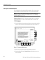
The System Calibration Menu . . . . . . . . . . . . . . . . . . . . . . . . . . . . . . . . . . . . . . .
Attenuator Adjustment . . . . . . . . . . . . . . . . . . . . . . . . . . . . . . . . . . . . . . . . . . . . .
Monitor Adjustments . . . . . . . . . . . . . . . . . . . . . . . . . . . . . . . . . . . . . . . . . . . . . .
5–1
5–2
5–4
5–6
Preventing ESD . . . . . . . . . . . . . . . . . . . . . . . . . . . . . . . . . . . . . . . . . . . . . . . . . .
General Care . . . . . . . . . . . . . . . . . . . . . . . . . . . . . . . . . . . . . . . . . . . . . . . . . . . . .
Inspection and Cleaning Procedures . . . . . . . . . . . . . . . . . . . . . . . . . . . . . . . . . .
6–1
6–2
6–2
Removal and Replacement . . . . . . . . . . . . . . . . . . . . . . . . . . . . . . . . . . .
6–5
Preparation — Please Read . . . . . . . . . . . . . . . . . . . . . . . . . . . . . . . . . . . . . . . . .
Line Fuse and Line Cord . . . . . . . . . . . . . . . . . . . . . . . . . . . . . . . . . . . . . . . . . . .
Front Panel Knobs and Shafts . . . . . . . . . . . . . . . . . . . . . . . . . . . . . . . . . . . . . . .
Rear Cover, Cabinet, and Cabinet Handle . . . . . . . . . . . . . . . . . . . . . . . . . . . . . .
Disk Drive . . . . . . . . . . . . . . . . . . . . . . . . . . . . . . . . . . . . . . . . . . . . . . . . . . . . . .
Trim Ring, Menu Elastomer, Menu Buttons, and Front EMI Gaskets . . . . . . . .
Front Panel Assembly and Menu Flex Circuit . . . . . . . . . . . . . . . . . . . . . . . . . . .
Main Board Assembly . . . . . . . . . . . . . . . . . . . . . . . . . . . . . . . . . . . . . . . . . . . . .
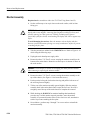
Monitor Assembly . . . . . . . . . . . . . . . . . . . . . . . . . . . . . . . . . . . . . . . . . . . . . . . .
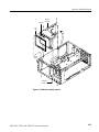
Power Supply Assembly . . . . . . . . . . . . . . . . . . . . . . . . . . . . . . . . . . . . . . . . . . .
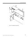
Option 14 Assembly . . . . . . . . . . . . . . . . . . . . . . . . . . . . . . . . . . . . . . . . . . . . . . .
Fan and Fan Mount . . . . . . . . . . . . . . . . . . . . . . . . . . . . . . . . . . . . . . . . . . . . . . .
6–5
6–8
6–10
6–11
6–13
6–14
6–16
6–20
6–24
6–26
6–28
6–31
Troubleshooting . . . . . . . . . . . . . . . . . . . . . . . . . . . . . . . . . . . . . . . . . . . .
6–33
Onboard Diagnostics . . . . . . . . . . . . . . . . . . . . . . . . . . . . . . . . . . . . . . . . . . . . . .
Enabling Calibration Menus . . . . . . . . . . . . . . . . . . . . . . . . . . . . . . . . . . . . . . . .
Troubleshooting Procedure . . . . . . . . . . . . . . . . . . . . . . . . . . . . . . . . . . . . . . . . .
Custom Selected Parts . . . . . . . . . . . . . . . . . . . . . . . . . . . . . . . . . . . . . . . . . . . . .
6–33
6–35
6–36
6–47
Repackaging Instructions . . . . . . . . . . . . . . . . . . . . . . . . . . . . . . . . . . . .
6–49
Maintenance
Options . . . . . . . . . . . . . . . . . . . . . . . . . . . . . . . . . . . . . . . . . . . . . . . . . . . . . . . . .
Standard Accessories . . . . . . . . . . . . . . . . . . . . . . . . . . . . . . . . . . . . . . . . . . . . . .
Optional Accessories . . . . . . . . . . . . . . . . . . . . . . . . . . . . . . . . . . . . . . . . . . . . . .
Accessory Probes . . . . . . . . . . . . . . . . . . . . . . . . . . . . . . . . . . . . . . . . . . . . . . . . .
Accessory Cables . . . . . . . . . . . . . . . . . . . . . . . . . . . . . . . . . . . . . . . . . . . . . . . . .
7–1
7–3
7–3
7–4
7–4
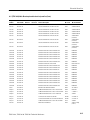
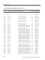
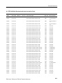
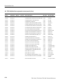
Electrical Parts List . . . . . . . . . . . . . . . . . . . . . . . . . . . . . . . . . . . . . . . . . . . . . . .
8–1
Diagrams . . . . . . . . . . . . . . . . . . . . . . . . . . . . . . . . . . . . . . . . . . . . . . . . . . . . . . .
9–1
Parts Ordering Information . . . . . . . . . . . . . . . . . . . . . . . . . . . . . . . . . . . . . . . . .
Using the Replaceable Parts List . . . . . . . . . . . . . . . . . . . . . . . . . . . . . . . . . . . . .
10–1
10–2
Electrical Parts List
Diagrams
Mechanical Parts List
ii
TDS 340A, TDS 360 & TDS 380 Technical Reference
Contents
List of Figures
Figure 1–1: Oscilloscope dimensions . . . . . . . . . . . . . . . . . . . . . . . . . . . .
1–11
Figure 2–1: A pop-up menu . . . . . . . . . . . . . . . . . . . . . . . . . . . . . . . . . . . .
Figure 2–2: Using menus . . . . . . . . . . . . . . . . . . . . . . . . . . . . . . . . . . . . .
2–8
2–9
Figure 3–1: Block diagram . . . . . . . . . . . . . . . . . . . . . . . . . . . . . . . . . . . .
Figure 3–2: Block diagram with Option 14 installed . . . . . . . . . . . . . . . .
Figure 3–3: Acquisition system block diagram . . . . . . . . . . . . . . . . . . . . .
3–2
3–3
3–8
Figure 4–1: Menu locations . . . . . . . . . . . . . . . . . . . . . . . . . . . . . . . . . . . .
Figure 4–2: Verifying adjustments and signal path
compensation . . . . . . . . . . . . . . . . . . . . . . . . . . . . . . . . . . . . . . . . . . .
Figure 4–3: Hookup for functional test . . . . . . . . . . . . . . . . . . . . . . . . . . .
Figure 4–4: Hookup for file system functional test . . . . . . . . . . . . . . . . . .
Figure 4–5: Hookup for DC voltage measurement
accuracy check . . . . . . . . . . . . . . . . . . . . . . . . . . . . . . . . . . . . . . . . . .
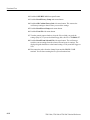
Figure 4–6: Hookup for analog bandwidth check . . . . . . . . . . . . . . . . . . .
Figure 4–7: Measuring analog bandwidth . . . . . . . . . . . . . . . . . . . . . . . . .
Figure 4–8: Hookup for sample rate check . . . . . . . . . . . . . . . . . . . . . . . .
Figure 4–9: Hookup for trigger sensitivity check . . . . . . . . . . . . . . . . . . .
Figure 4–10: Measuring trigger sensitivity . . . . . . . . . . . . . . . . . . . . . . . .
Figure 4–11: Hookup for sine wave generator leveling . . . . . . . . . . . . . .
4–2
4–12
4–14
4–15
4–16
4–18
4–19
4–21
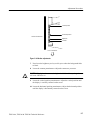
Figure 5–1: The system calibration menu . . . . . . . . . . . . . . . . . . . . . . . . .
Figure 5–2: Timing compensation waveform . . . . . . . . . . . . . . . . . . . . . .
Figure 5–3: Attenuator adjustment setup and locations . . . . . . . . . . . . . .
Figure 5–4: Monitor adjustments . . . . . . . . . . . . . . . . . . . . . . . . . . . . . . .
5–2
5–4
5–5
5–7
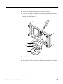
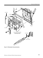
Figure 6–1: Oscilloscope orientation . . . . . . . . . . . . . . . . . . . . . . . . . . . .
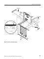
Figure 6–2: Line cord removal . . . . . . . . . . . . . . . . . . . . . . . . . . . . . . . . .
Figure 6–3: Line fuse removal . . . . . . . . . . . . . . . . . . . . . . . . . . . . . . . . .
Figure 6–4: Knob and shaft removal . . . . . . . . . . . . . . . . . . . . . . . . . . . . .
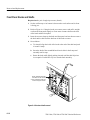
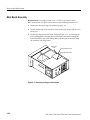
Figure 6–5: Rear cover, cabinet, and cabinet handle
and feet removal . . . . . . . . . . . . . . . . . . . . . . . . . . . . . . . . . . . . . . . . .
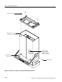
Figure 6–6: Removing the disk drive . . . . . . . . . . . . . . . . . . . . . . . . . . . .
Figure 6–7: Trim ring, menu elastomer, and
menu buttons removal . . . . . . . . . . . . . . . . . . . . . . . . . . . . . . . . . . . . .
6–6
6–8
6–9
6–10
TDS 340A, TDS 360 & TDS 380 Technical Reference
4–6
4–7
4–9
6–12
6–13
6–14
iii
Contents
Figure 6–8: EMI gasket removal and installation . . . . . . . . . . . . . . . . . . .
Figure 6–9: Front panel assembly and menu
flex circuit removal . . . . . . . . . . . . . . . . . . . . . . . . . . . . . . . . . . . . . . .
Figure 6–10: Disassembly of front-panel assembly . . . . . . . . . . . . . . . . .
Figure 6–11: Removing the floppy interface board . . . . . . . . . . . . . . . . .
Figure 6–12: Removing the main board . . . . . . . . . . . . . . . . . . . . . . . . . .
Figure 6–13: BNC and hybrid removal . . . . . . . . . . . . . . . . . . . . . . . . . .
Figure 6–14: Monitor assembly removal . . . . . . . . . . . . . . . . . . . . . . . . .
Figure 6–15: Low voltage power supply removal . . . . . . . . . . . . . . . . . . .
Figure 6–16: Option 14 assembly removal . . . . . . . . . . . . . . . . . . . . . . . .
Figure 6–17: Option 14 disassembly . . . . . . . . . . . . . . . . . . . . . . . . . . . . .
Figure 6–18: Fan and fan mount removal . . . . . . . . . . . . . . . . . . . . . . . . .
Figure 6–19: The diagnostics menu . . . . . . . . . . . . . . . . . . . . . . . . . . . . .
Figure 6–20: The error log . . . . . . . . . . . . . . . . . . . . . . . . . . . . . . . . . . . .
Figure 6–21: Main board cal jumper . . . . . . . . . . . . . . . . . . . . . . . . . . . . .
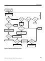
Figure 6–22: Primary troubleshooting procedure . . . . . . . . . . . . . . . . . . .
Figure 6–23: Module isolation troubleshooting
procedure . . . . . . . . . . . . . . . . . . . . . . . . . . . . . . . . . . . . . . . . . . . . . . .
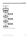
Figure 6–24: Front panel/processor troubleshooting
procedure . . . . . . . . . . . . . . . . . . . . . . . . . . . . . . . . . . . . . . . . . . . . . . .
Figure 6–25: Monitor troubleshooting procedure . . . . . . . . . . . . . . . . . . .
Figure 6–26: J901 pin 7 signal . . . . . . . . . . . . . . . . . . . . . . . . . . . . . . . . .
Figure 6–27: J901 pin 2 signal . . . . . . . . . . . . . . . . . . . . . . . . . . . . . . . . .
Figure 6–28: J901 pin 5 signal . . . . . . . . . . . . . . . . . . . . . . . . . . . . . . . . .
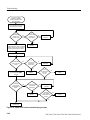
Figure 6–29: Power supply troubleshooting procedure . . . . . . . . . . . . . .
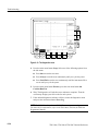
Figure 6–30: Power supply connector locations . . . . . . . . . . . . . . . . . . . .
Figure 6–31: Power supply overload troubleshooting
procedure . . . . . . . . . . . . . . . . . . . . . . . . . . . . . . . . . . . . . . . . . . . . . . .
Figure 6–32: Option 14 I/O interfaces troubleshooting
procedure . . . . . . . . . . . . . . . . . . . . . . . . . . . . . . . . . . . . . . . . . . . . . . .
Figure 9–1: A2 Option 14 board . . . . . . . . . . . . . . . . . . . . . . . . . . . . . . . .
Figure 9–2: A3 Printer Power board (Option 14) . . . . . . . . . . . . . . . . . . .
Figure 9–3: A5 Floppy Interface board . . . . . . . . . . . . . . . . . . . . . . . . . . .
Figure 9–4: A6 Front Panel board (front) . . . . . . . . . . . . . . . . . . . . . . . . .
Figure 9–5: A6 Front Panel board (back) . . . . . . . . . . . . . . . . . . . . . . . . .
Figure 9–6: A6 Front Panel component locator . . . . . . . . . . . . . . . . . . . .
Figure 9–7: A11, A12 Main board (TDS 340A, TDS 360)
(section A, B) . . . . . . . . . . . . . . . . . . . . . . . . . . . . . . . . . . . . . . . . . . .
iv
6–16
6–17
6–19
6–20
6–21
6–22
6–25
6–27
6–29
6–30
6–31
6–34
6–35
6–36
6–37
6–38
6–39
6–40
6–41
6–41
6–42
6–43
6–44
6–45
6–46
9–2
9–8
9–10
9–12
9–13
9–14
9–22
TDS 340A, TDS 360 & TDS 380 Technical Reference
Contents
Figure 9–8: A11, A12 Main board (TDS 340A, TDS 360)
(section C, D) . . . . . . . . . . . . . . . . . . . . . . . . . . . . . . . . . . . . . . . . . . .
Figure 9–9: A11, A12 component locator (TDS 340A, TDS 360) . . . . . .
Figure 9–10: A11, A12 component locator (TDS 340A, TDS 360)
(cont.) . . . . . . . . . . . . . . . . . . . . . . . . . . . . . . . . . . . . . . . . . . . . . . . . .
Figure 9–11: A13 Main board (TDS 380) (section A, B) . . . . . . . . . . . . .
Figure 9–12: A13 Main board (TDS 380) (section C, D) . . . . . . . . . . . . .
Figure 9–13: A13 Main component locator (TDS 380) . . . . . . . . . . . . . .
Figure 9–14: A26 Monitor board . . . . . . . . . . . . . . . . . . . . . . . . . . . . . . . .
Figure 9–15: A26 Monitor component locator . . . . . . . . . . . . . . . . . . . . .
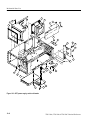
Figure 10–1: Cabinet and front panel assembly . . . . . . . . . . . . . . . . . . . .
Figure 10–2: CRT, power supply, and circuit boards . . . . . . . . . . . . . . . .
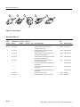
Figure 10–3: Accessories . . . . . . . . . . . . . . . . . . . . . . . . . . . . . . . . . . . . . .
TDS 340A, TDS 360 & TDS 380 Technical Reference
9–23
9–24
9–25
9–42
9–43
9–44
9–60
9–61
10–6
10–8
10–10
v
Contents
List of Tables
vi
Table 1–1: Warranted characteristics — signal acquisition
system . . . . . . . . . . . . . . . . . . . . . . . . . . . . . . . . . . . . . . . . . . . . . . . .
Table 1–2: Warranted characteristics — time base system . . . . . . . . . . .
Table 1–3: Warranted characteristics — triggering system . . . . . . . . . . .
Table 1–4: Power Requirements . . . . . . . . . . . . . . . . . . . . . . . . . . . . . . . .
Table 1–5: Warranted characteristics — environmental . . . . . . . . . . . . . .
Table 1–6: Typical characteristics — signal acquisition system . . . . . . .
Table 1–7: Typical characteristics — triggering system . . . . . . . . . . . . .
Table 1–8: Typical characteristics — probe compensator output . . . . . . .
Table 1–9: Typical characteristics — data handling . . . . . . . . . . . . . . . . .
Table 1–10: Nominal traits — signal acquisition system . . . . . . . . . . . . .
Table 1–11: Nominal traits — time base system . . . . . . . . . . . . . . . . . . .
Table 1–12: Nominal traits — triggering system . . . . . . . . . . . . . . . . . . .
Table 1–13: Nominal traits — display system . . . . . . . . . . . . . . . . . . . . .
Table 1–14: Nominal traits — Option 14 I/O interface option
(TD3F14A) . . . . . . . . . . . . . . . . . . . . . . . . . . . . . . . . . . . . . . . . . . . .
Table 1–15: Nominal traits — power distribution system . . . . . . . . . . . .
Table 1–16: Nominal traits — mechanical characteristics . . . . . . . . . . . .
Table 1–17: Certifications and compliances . . . . . . . . . . . . . . . . . . . . . . .
1–9
1–9
1–10
1–12
Table 4–1: Test equipment . . . . . . . . . . . . . . . . . . . . . . . . . . . . . . . . . . . .
Table 4–2: DC accuracy . . . . . . . . . . . . . . . . . . . . . . . . . . . . . . . . . . . . . .
4–3
4–11
Table 5–1: Adjustment equipment . . . . . . . . . . . . . . . . . . . . . . . . . . . . . .
5–1
Table 6–1: External inspection check list . . . . . . . . . . . . . . . . . . . . . . . . .
Table 6–2: Internal inspection check list . . . . . . . . . . . . . . . . . . . . . . . . .
Table 6–3: Tools required for module removal . . . . . . . . . . . . . . . . . . . .
Table 6–4: Power supply secondary voltages . . . . . . . . . . . . . . . . . . . . . .
6–3
6–4
6–6
6–40
1–1
1–2
1–3
1–3
1–4
1–5
1–6
1–6
1–7
1–7
1–8
1–8
1–9
TDS 340A, TDS 360 & TDS 380 Technical Reference
Contents
Table 7–1: VGA output connector pins . . . . . . . . . . . . . . . . . . . . . . . . . .
Table 7–2: International power cords . . . . . . . . . . . . . . . . . . . . . . . . . . . .
Table 7–3: Language options . . . . . . . . . . . . . . . . . . . . . . . . . . . . . . . . . .
Table 7–4: Standard accessories . . . . . . . . . . . . . . . . . . . . . . . . . . . . . . . .
Table 7–5: Optional accessories . . . . . . . . . . . . . . . . . . . . . . . . . . . . . . . .
Table 7–6: Accessory cables . . . . . . . . . . . . . . . . . . . . . . . . . . . . . . . . . . .
TDS 340A, TDS 360 & TDS 380 Technical Reference
7–1
7–2
7–2
7–3
7–3
7–4
vii
Contents
viii
TDS 340A, TDS 360 & TDS 380 Technical Reference
General Safety Summary
Review the following safety precautions to avoid injury and prevent damage to
this product or any products connected to it. To avoid potential hazards, use the
product only as specified.
Only qualified personnel should perform service procedures.
While using this product, you may need to access other parts of the system. Read
the General Safety Summary in other system manuals for warnings and cautions
related to operating the system.
Injury Precautions
Use Proper Power Cord. To avoid fire hazard, use only the power cord specified
for this product.
Avoid Electric Overload. To avoid electric shock or fire hazard, do not apply a
voltage to a terminal that is outside the range specified for that terminal.
Avoid Overvoltage. To avoid electric shock or fire hazard, do not apply potential
to any terminal, including the common terminal, that varies from ground by
more than the maximum rating for that terminal.
Avoid Electric Shock. To avoid injury or loss of life, do not connect or disconnect
probes or test leads while they are connected to a voltage source.
Ground the Product. This product is grounded through the grounding conductor
of the power cord. To avoid electric shock, the grounding conductor must be
connected to earth ground. Before making connections to the input or output
terminals of the product, ensure that the product is properly grounded.
Do Not Operate Without Covers. To avoid electric shock or fire hazard, do not
operate this product with covers or panels removed.
Use Proper Fuse. To avoid fire hazard, use only the fuse type and rating specified
for this product.
Do Not Operate in Wet/Damp Conditions. To avoid electric shock, do not operate
this product in wet or damp conditions.
Do Not Operate in an Explosive Atmosphere. To avoid injury or fire hazard, do not
operate this product in an explosive atmosphere.
Avoid Exposed Circuitry. To avoid injury, remove jewelry such as rings, watches,
and other metallic objects. Do not touch exposed connections and components
when power is present.
Keep Probe Surface Clean and Dry. To avoid electric shock and erroneous
readings, keep probe surface clean and dry.
TDS 340A, TDS 360 & TDS 380 Technical Reference
ix
General Safety Summary
Wear Eye Protection. To avoid eye injury, wear eye protection if there is a
possibility of exposure to high-intensity rays.
Product Damage
Precautions
Use Proper Power Source. Do not operate this product from a power source that
applies more than the voltage specified.
Provide Proper Ventilation. To prevent product overheating, provide proper
ventilation.
Do Not Operate With Suspected Failures. If you suspect there is damage to this
product, have it inspected by qualified service personnel.
Do Not Immerse in Liquids. Clean the probe using only a damp cloth. Refer to
cleaning instructions.
Symbols and Terms
Terms in this Manual. These terms may appear in this manual:
WARNING. Warning statements identify conditions or practices that could result
in injury or loss of life.
CAUTION. Caution statements identify conditions or practices that could result in
damage to this product or other property.
Terms on the Product. These terms may appear on the product:
DANGER indicates an injury hazard immediately accessible as you read the
marking.
WARNING indicates an injury hazard not immediately accessible as you read the
marking.
CAUTION indicates a hazard to property including the product.
Symbols on the Product. The following symbols may appear on the product:
DANGER
High Voltage
Certifications and
Compliances
x
Protective Ground
(Earth) Terminal
ATTENTION
Refer to Manual
Double
Insulated
Refer to the specifications section for a listing of certifications and compliances
that apply to this product.
TDS 340A, TDS 360 & TDS 380 Technical Reference
Service Safety Summary
Only qualified personnel should perform service procedures. Read this Service
Safety Summary and the General Safety Summary before performing any service
procedures.
Do Not Service Alone. Do not perform internal service or adjustments of this
product unless another person capable of rendering first aid and resuscitation is
present.
Disconnect Power. To avoid electric shock, disconnect the main power by means
of the power cord or, if provided, the power switch.
Use Caution When Servicing the CRT. To avoid electric shock or injury, use
extreme caution when handling the CRT. Only qualified personnel familiar with
CRT servicing procedures and precautions should remove or install the CRT.
CRTs retain hazardous voltages for long periods of time after power is turned off.
Before attempting any servicing, discharge the CRT by shorting the anode to
chassis ground. When discharging the CRT, connect the discharge path to ground
and then the anode. Rough handling may cause the CRT to implode. Do not nick
or scratch the glass or subject it to undue pressure when removing or installing it.
When handling the CRT, wear safety goggles and heavy gloves for protection.
Use Care When Servicing With Power On. Dangerous voltages or currents may
exist in this product. Disconnect power, remove battery (if applicable), and
disconnect test leads before removing protective panels, soldering, or replacing
components.
To avoid electric shock, do not touch exposed connections.
X-Radiation. To avoid x-radiation exposure, do not modify or otherwise alter the
high-voltage circuitry or the CRT enclosure. X-ray emissions generated within
this product have been sufficiently shielded.
TDS 340A, TDS 360 & TDS 380 Technical Reference
xi
Service Safety Summary
xii
TDS 340A, TDS 360 & TDS 380 Technical Reference
Preface
This technical reference manual provides service information for the TDS 340A,
TDS 360, and TDS 380 Digitizing Oscilloscopes.
Manual Structure
This manual is divided into Chapters such as Specifications and Theory of
Operation. Further, it is divided into subsections such as Product Description
and Removal and Installation Procedures.
Sections containing procedures also contain introductions to those procedures.
Be sure to read these introductions because they provide information needed to
do the service correctly and efficiently. The following is a brief description of
each manual chapter.
Specifications contains a product description of the digitizing oscilloscope
and tables of the characteristics and descriptions that apply to it.
Operating Information includes general information and operating instructions at the level needed to safely power on and service this oscilloscope.
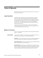
Theory of Operation contains circuit descriptions that support general service
and fault isolation down to the module level.
Performance Verification contains a collection of procedures for confirming
that this digitizing oscilloscope functions properly and meets warranted
limits.
Adjustment Procedures contains a collection of procedures for adjusting this
digitizing oscilloscope to meet warranted limits.
Maintenance contains information and procedures for doing preventive and
corrective maintenance of the digitizing oscilloscope. Instructions for
cleaning, for module removal and installation, and for fault isolation to a
module are found here.
Options contains information on the factory-installed options that may be
present in your oscilloscope.
Electrical Parts List contains a component-level list grouped by board
assembly.
TDS 340A, TDS 360 & TDS 380 Technical Reference
xiii
Preface
Diagrams contains component location and schematic diagrams.
Mechanical Parts List includes a table of all replaceable modules, their
descriptions, and their Tektronix part numbers.
Manual Conventions
This manual uses certain conventions which you should become familiar with
before doing service.
Modules
Throughout this manual, any replaceable component, assembly, or part of this
digitizing oscilloscope is referred to generically as a module. In general, a
module is an assembly, like a circuit board, rather than a component, like a
resistor or an integrated circuit. Sometimes a single component is a module; for
example, the chassis of the oscilloscope is a module.
Safety
Symbols and terms related to safety appear in the General Safety Summary and
Service Safety Summary found at the beginning of this manual.
Symbols
Besides the symbols related to safety, this manual uses the following symbols:
STOP. This “stop sign” labels information which you must read in order to
correctly do service and to avoid incorrectly using or applying
service procedures.
Related Manuals
These other manuals are available for the TDS 340A, TDS 360, and TDS 380
Digitizing Oscilloscopes.
xiv
The Reference Manual gives you a quick overview of how to operate your
oscilloscope.
The User Manual provides instructions on how to operate your oscilloscope.
The Programmer Manual provides complete information on programming
and remote control of the oscilloscope through the GPIB or RS-232 interface
(optional accessory).
TDS 340A, TDS 360 & TDS 380 Technical Reference
Specifications
This appendix contains complete specifications for the TDS 340A, TDS 360, and
TDS 380. The specifications are divided into three subsections, one for each of
three classes of traits: Warranted Characteristics, Typical Characteristics, and
Nominal Traits.
Warranted Characteristics
Warranted characteristics are described in terms of quantifiable performance
limits that are warranted. This subsection lists only warranted characteristics.
NOTE. In these tables, those warranted characteristics that are checked in the
Performance Tests, starting on page 4–11, appear in boldface type under the
column Name.
Performance Conditions
The electrical characteristics found in these tables of warranted characteristics
apply when the oscilloscope has been adjusted at an ambient temperature
between +20_ C and +30_ C, has had a warm-up period of at least 20 minutes,
and is operating at an ambient temperature between –10_ C and +55_ C (unless
otherwise noted).
Table 1–1: Warranted characteristics — signal acquisition system
Name
Description
Accuracy, DC Voltage Measurement,
ui i i M
de
Average Ac
Acquisition
Mode
Measurement type
DC accuracy
Average of ≥16 waveforms
±(2.0% × |(reading – Net Offset1)| + Offset
Accuracy + 0.1 div)
Delta volts between any two averages of
≥16 waveforms acquired under the same
setup and ambient conditions
±(2.0% × |reading| + 0.15 div + 0.3 mV)
Accuracy, DC Gain, Sample or
Average Acquisition Modes
±2%
Pulse Response, Peak Detect and
E vel pe Mode
M de
Envelope
Sec/Div setting
Minimum pulse width
5 s/div – 25 s/div
10 ns
TDS 340A: 10 s/div – 5 ns/div
TDS 360: 10 s/div – 2.5 ns/div
TDS 380: 10 s/div – 1 ns/div
The greater of 10 ns or
.02 × sec/div setting
TDS 340A, TDS 360 & TDS 380 Technical Reference
1–1
Specifications
Table 1–1: Warranted characteristics — signal acquisition system (Cont.)
Name
Description
Accuracy, Offset
Volts/Div setting
Offset accuracy
2 mV/div – 99.5 mV/div
±(0.4% × |Net Offset1|
+ 3 mV + 0.1 div × V/div setting)
100 mV/div – 995 mV/div
±(0.4% × |Net Offset1|
+ 30 mV + 0.1 div × V/div setting)
1 V/div – 10 V/div
±(0.4% × |Net Offset1|
+ 300 mV + 0.1 div × V/div setting)
Analog Bandwidth, DC Coupled
TDS 340A: DC – ≥100 MHz
TDS 360: DC – ≥200 MHz; DC – ≥180 MHz for 2 mV/div
TDS 380: DC – ≥400 MHz; DC – ≥250 MHz for 2 mV/div
Cross Talk (Channel Isolation)
≥100:1 at 50 MHz with equal Volts/Div settings on each channel
Input Impedance, DC-Coupled
TDS 340A: 1 MW ±1% in parallel with 20 pF ±2.0 pF
TDS 360: 1 MW ±1% in parallel with 20 pF ±2.0 pF
TDS 380: 1 MW ±1% in parallel with 12 pF ±2.0 pF
Input Voltage, Maximum
±300 V (DC or AC) CAT II; derate at 20 dB/decade above 100 kHz to 13 V peak AC at
3 MHz and above
Lower Frequency Limit, AC Coupled2
≤10 Hz
1
Net Offset = Offset – (Position × Volts/Div). Net offset is the voltage level at the center of the A-D converter dynamic
range. Offset Accuracy is the accuracy of this voltage level.
2
The AC Coupled Lower Frequency Limits are reduced by a factor of 10 when 10X, passive probes are used.
Table 1–2: Warranted characteristics — time base system
Name
Description
Accuracy, Long Term Sample Rate and
Delay Time
±100 ppm over any ≥1 ms interval
Accuracy, Delta Time Measurements1, 2
For single-shot acquisitions using sample acquisition mode and a bandwidth limit setting
of FULL:
±(1 WI + 100 ppm × |Reading| + 0.6 ns)
For repetitive acquisitions using average acquisition mode with ≥16 averages and a
bandwidth limit setting of FULL:
±(1 WI + 100 ppm × |Reading| + 0.4 ns)
1
For input signals ≥5 divisions in amplitude and a slew rate of ≥2.0 divisions/ns at the delta time measurement points.
Signal must be acquired at a volts/division setting ≥5 mV/division.
2
The WI (waveform interval) is the time between the samples in the waveform record. Also, see the footnotes for Sample
Rate Range and Equivalent Time or Interpolated Waveform Rates in Table 1–11 on page 1–8.
1–2
TDS 340A, TDS 360 & TDS 380 Technical Reference
Specifications
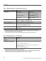
Table 1–3: Warranted characteristics — triggering system
Name
Description
Accuracy, Trigger Level, DC Coupled
Trigger source
Sensitivity
CH1 or CH2
±(3% of |Setting – Net Offset1| + 0.2 div ×
volts/div setting + Offset Accuracy)
External
±(6% of |Setting| + 20 mV)
External/10
±(6% of |Setting| + 200 mV)
Trigger source
Sensitivity
CH1 or CH2
TDS 340A: 0.35 division from DC to 20
MHz, increasing to 1 div at 100 MHz
Sensitivity, Edge-Type Trigger, DC
Coupled
upled
TDS 360: 0.35 division from DC to 50 MHz,
increasing to 1 div at 200 MHz
TDS 380: 0.35 division from DC to 50 MHz,
increasing to 1 div at 400 MHz
External
TDS 340A: 50 mV from DC to 20 MHz,
increasing to 150 mV at 100 MHz
TDS 360: 50 mV from DC to 50 MHz,
increasing to 150 mV at 200 MHz
TDS 380: 50 mV from DC to 50 MHz,
increasing to 500 mV at 400 MHz
External/10
TDS 340A: 500 mV from DC to 20 MHz,
increasing to 1.5 V at 100 MHz
TDS 360: 500 mV from DC to 50 MHz,
increasing to 1.5 V at 200 MHz
TDS 380: 500 mV from DC to 50 MHz,
increasing to 5.0 V at 400 MHz
Input Impedance, External Trigger
1 MW ±2% in parallel with 20 pF ±2 pF
Maximum Input Voltage,
External Trigger
±300 V (DC or AC) CAT II; derate at 20 dB/decade above 100 kHz to 13 V peak AC at
3 MHz and above
1
Net Offset = Offset – (Position × Volts/Div). Net Offset is the voltage level at the center of the A-D converter dynamic
range. Offset Accuracy is the accuracy of this voltage level.
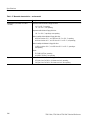
Table 1–4: Power Requirements
Name
Description
Source Voltage and Frequency
90 to 132 VACRMS, continuous range, for 47 Hz through 440 Hz
132 to 250 VACRMS, continuous range, for 47 Hz through 63 Hz
Power Consumption
≤65 Watts (120 VA)
TDS 340A, TDS 360 & TDS 380 Technical Reference
1–3
Specifications
Table 1–5: Warranted characteristics — environmental
Name
Description
Atmospherics (TDS 340A, TDS 360 or
TDS 380)
Temperature without diskette in floppy disk drive:
+4_ C to +50_ C, operating;
–22_ C to +60_ C, non-operating
Temperature with diskette in floppy disk drive:
+10_ C to +50_ C, operating or non-operating
Relative humidity without diskette in floppy disk drive:
to 80% at or below +29_ C, or to 20% from +30_ C to +50_ C, operating;
to 90% at or below +40_ C, or to 5% from +41_ C to +50_ C, non-operating;
Relative humidity with diskette in floppy disk drive:
to 80% at or below +29_ C, or to 20% from +30_ C to +50_ C, operating or
non-operating
Altitude:
To 15,000 ft (4570 m), operating;
to 40,000 ft (12190 m), non-operating
Dynamics
Random vibration without diskette in floppy disk drive:
0.31 g RMS, from 5 to 500 Hz, 10 minutes each axis, operating;
2.46 g RMS, from 5 to 500 Hz, 10 minutes each axis, non-operating
1–4
TDS 340A, TDS 360 & TDS 380 Technical Reference
Specifications
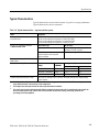
Typical Characteristics
Typical characteristics are described in terms of typical or average performance.
Typical characteristics are not warranted.
Table 1–6: Typical characteristics — signal acquisition system
Name
Description
Accuracy, DC Gain, Envelope
Acquisition Mode
±3% for sec/div settings from 5 Sec/Div to 25 sec/div;
±2% for sec/div settings from 10 s/div to 5 ns/div (TDS 340A);
±2% for sec/div settings from 10 s/div to 2.5 ns/div (TDS 360);
±2% for sec/div settings from 10 s/div to 1 ns/div (TDS 380)
Accuracy, DC Voltage Measurement,
Sample
m le Ac
Acquisition
isitio Mode
o e
Measurement type
DC accuracy
Any Sample
±(2.0% × (|reading – Net Offset1|) + Offset
Accuracy + 0.13 div + 0.6 mV)
Delta Volts between any two samples2
acquired under the same setup and
ambient conditions
±(2.0% × |reading| + 0.26 div + 1.2 mV)
Frequency Limit, Upper, 20 MHz Bandwidth Limited
20 MHz
Step Response Settling Error
Volts/Div
setting
e i g
Step
a pli ude
amplitude
Settling error (%)3
100 ns
20 ms
2 mV/div – 99.5 mV/div
≤2 V
≤1.0
≤0.1
100 mV/div – 995 mV/div
≤20 V
≤1.5
≤0.2
1 V/div – 10 V/div
≤200 V
≤2.5
≤0.2
Common Mode Rejection Ratio (CMRR)
100:1 at 60 Hz, reducing to 20:1 at 50 MHz, with equal Volts/Div and Coupling settings
on each channel.
1
Net Offset = Offset – (Position × Volts/Div). Net Offset is the voltage level at the center of the A-D converter dynamic
range. Offset Accuracy is the accuracy of this voltage level.
2
The samples must be acquired under the same setup and ambient conditions.
3
The values given are the maximum absolute difference between the value at the end of a specified time interval after the
mid-level crossing of the step, and the value one second after the mid-level crossing of the step, expressed as a
percentage of the step amplitude.
TDS 340A, TDS 360 & TDS 380 Technical Reference
1–5
Specifications
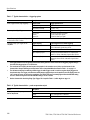
Table 1–7: Typical characteristics — triggering system
Name
Description
Error, Trigger Position, Edge Triggering
Acquire mode
Trigger-position error1,2
Sample, Average
±(1 WI + 2 ns)
Peak Detect, Envelope
±(2 WI + 2 ns)
Source
Typical sensitivity
CH1 or CH2
External
External/10
0.6 division of video sync signal
75 mV of video sync signal
750 mV of video sync signal
Sensitivity, Video-Type Trigger
Lowest Frequency for Successful Operation 50 Hz
of “Set Level to 50%” Function
Sensitivity, Edge Type Trigger, Not DC
Coupled
o le 3
Trigger coupling
Typical signal level for stable triggering
AC
Same as DC-coupled limits4 for frequencies above
60 Hz. Attenuates signals below 60 Hz.
Noise Reject
Three and one half times the DC-coupled limits.4
High Frequency Reject
One and one half times times the DC-coupled limits4
from DC to 30 kHz. Attenuates signals above 30 kHz.
Low Frequency Reject
One and one half times the DC-coupled limits4 for
frequencies above 80 kHz. Attenuates signals below
80 kHz.
1
The trigger position errors are typically less than the values given here. These values are for triggering signals having a
slew rate at the trigger point of ±0.5 division/ns.
2
The waveform interval (WI) is the time between the samples in the waveform record. Also, see the footnote for the
characteristics Sample Rate Range and Equivalent Time or Interpolated Waveform Rates in Table 1–11 on page 1–8.
3
The minimum sensitivity for obtaining a stable trigger. A stable trigger results in a uniform, regular display triggered on
the selected slope. The trigger point must not switch between opposite slopes on the waveform, and the display must not
“roll” across the screen on successive acquisitions. The TRIG’D LED stays constantly lighted when the SEC/DIV setting
is 2 ms or faster but may flash when the SEC/DIV setting is 10 ms or slower.
4
See the characteristic Sensitivity, Edge-Type Trigger, DC Coupled in Table 1–3, which begins on page 1–3.
Table 1–8: Typical characteristics — probe compensator output
Name
Description
Output Voltage and Frequency,
Pro e Compensator
Probe
om e s tor
Characteristic
1–6
Voltage
5.0 V (low-high) into a 1 MW load
Frequency
1 kHz
TDS 340A, TDS 360 & TDS 380 Technical Reference
Specifications
Table 1–9: Typical characteristics — data handling
Name
Description
Time, Data-Retention, Nonvolatile
Memory1,2
≥5 Years
1
The time that reference waveforms, stored setups, and calibration constants are retained when there is no power to the
oscilloscope.
2
Data is maintained by a lithium poly-carbon monofluoride battery.
Nominal Traits
Nominal traits are described using simple statements of fact such as “Two,
identical” for the trait “Input Channels, Number of,” rather than in terms of
limits that are performance requirements.
Table 1–10: Nominal traits — signal acquisition system
Name
Description
Bandwidth Selections
20 MHz and FULL
Digitizers, Number of
Two, identical, digitized simultaneously
Digitized Bits, Number of
8 bits1
Input Channels, Number of
Two, identical, called CH 1 and CH 2
Input Coupling
DC, AC, or GND
Ranges, Offset, All Channels
Volts/Div setting
Offset range
2 mV/div – 99.5 mV/div
±1 V
100 mV/div – 995 mV/div
±10 V
1 V/div – 10 V/div
±100 V
Range, Position
±5 divisions
Range, Sensitivity2
2 mV/div to 10 V/div
Rise Time
TDS 340A: 3.5 ns
TDS 360: 1.75 ns
TDS 380: 875 ps
TekProbe Interface
Level one probe coding
1
Displayed vertically with 25 digitization levels (DLs) per division and 10.24 divisions dynamic range with zoom off. A DL
is the smallest voltage level change that the 8-bit A-D Converter can resolve, with the input scaled to the volts/division
setting of the channel used. Expressed as a voltage, a DL is equal to 1/25 of a division times the volts/division setting.
2
The sensitivity ranges from 2 mV/div to 10 V/div in a 1–2–5 sequence of coarse settings. Between consecutive coarse
settings, the sensitivity can be finely adjusted with a resolution of 1% of the more sensitive setting. For example, between
50 mV/div and 100 mV/div, the volts/division can be set with 0.5 mV resolution.
TDS 340A, TDS 360 & TDS 380 Technical Reference
1–7
Specifications
Table 1–11: Nominal traits — time base system
Name
Description
Range, Sample-Rate1,2
TDS 340A: 10 Samples/s to 500 MSamples/s in a 1–2–5 sequence
TDS 360: 10 Samples/s to 1 GSamples/s in a 1–2–5 sequence
TDS 380: 10 Samples/s to 2 GSamples/s in a 1–2–5 sequence
Range, Seconds/Division
TDS 340A: 5 ns/div to 5 s/div in a 1–2.5–5 sequence
TDS 360: 2.5 ns/div to 5 s/div in a 1–2.5–5 sequence
TDS 380: 1 ns/div to 5 s/div in a 1–2.5–5 sequence
Range, Time Base Delay Time
16.5 ns to 50 seconds
Record Length
1,000 samples
1
The range of real-time rates, expressed in samples/second, at which a digitizer samples signals at its inputs and stores
the samples in memory to produce a record of time-sequential samples
2
The Waveform Rate (WR) is the equivalent sample rate of a waveform record. For a waveform record acquired by
real-time sampling of a single acquisition, the waveform rate is the same as the real-time sample rate; for a waveform
created by interpolation of real-time samples from a single acquisition or by equivalent-time sampling of multiple
acquisitions, the waveform rate is faster than the real time sample rate. For all three cases, the waveform rate is
1/(Waveform Interval) for the waveform record, where the waveform interval (WI) is the time between the samples in the
waveform record.
Table 1–12: Nominal traits — triggering system
Name
Description
Range, Hold Off
500 ns minimum to 10 seconds maximum
Ranges, Trigger Level
Source
Range
Any Channel
±12 divisions from center of screen
External
±1.5 Volts
External /10
±15 Volts
Line
±300 Volts
Formats and Field Rates, Video Trigger
Triggers from sync-negative composite video, 525 to 625 lines, 50 Hz to 60 Hz, interlaced
or noninterlaced systems with scan rates from 15 kHz to 65 kHz – such as NTSC, PAL, or
SECAM
TekProbe Interface, External Trigger
Level one probe coding
1–8
TDS 340A, TDS 360 & TDS 380 Technical Reference
Specifications
Table 1–13: Nominal traits — display system
Name
Description
CRT Type
7-inch (17.95 cm) diagonal, magnetic deflection; horizontal raster-scan; P31 green
phosphor
Video Display Resolution
640 pixels horizontally by 480 pixels vertically
Display area is 5.04 inch (12.92 cm) horizontally by 3.78 inch (9.69 cm) vertically
Waveform Display Graticule
A single graticule 401 × 501 pixels (8 × 10 divisions, with divisions that are approximately
1 cm by 1 cm)
Intensity Levels
Dim and Bright, with adjustable Overall Intensity and Contrast
Table 1–14: Nominal traits — I/O interface option
Name
Description
GPIB
Part of Option 14 I/O interface or TD3F14A I/O interface field upgrade kit; complies with
IEEE Std 488–1987
RS-232
Part of Option 14 I/O interface or TD3F14A I/O interface field upgrade kit; a 9-pin male
DTE RS-232 interface that complies with EIA/TIA 574–90
Centronics
Part of Option 14 I/O interface or TD3F14A I/O interface field upgrade kit; a 25-pin, IBM
PC-type, parallel printer interface that complies electrically with Centronics C332–44,
Rev A
Video Signal Output
(Option 14 Only)
DB-9 rear panel Video connector; non-interlaced, with levels that comply with ANSI
RS343A
VGA compatible at a 30.6 kHz sync rate
Power Supply, Printer
(Option 14 Only)
Power supply connector to supply power to the Option 3P Printer Pack
Table 1–15: Nominal traits — power distribution system
Name
Description
Fuse Rating
5 mm × 20 mm, 3.15 A (T), 250 V; or 1.25 in × 0.25 in, 3 A (T), 250 V
TDS 340A, TDS 360 & TDS 380 Technical Reference
1–9
Specifications
Table 1–16: Nominal traits — mechanical characteristics
Name
Description
Weight
Standard TDS 340A, TDS 360 or
TDS 380
7.0 kg (15.5 lbs) stand-alone instrument;
8.6 kg (19 lbs) with front cover, accessories, and accessories pouch installed;
12.9 kg (28.5 lbs) when packaged for domestic shipment
Rackmount TDS 340A, TDS 360 or
TDS 380
6.6 kg (14.5 lbs), plus weight of rackmount parts, for TDS 360 or TDS 380 (Option 1R);
14.7 kg (32.5 lbs) when the rackmounted TDS 360 or TDS 380 is packaged for domestic
shipment
Rackmount conversion kit
4.5 kg (10 lbs); 7.5 kg (17.5 lbs) when kit is packaged for domestic shipment
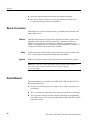
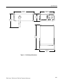
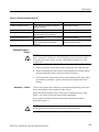
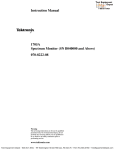
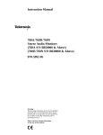
Overall Dimensions
Standard Instrument (Figure 1–1)
Rackmount Instrument
1–10
Height:
191 mm (7.5 in) with feet and accessories pouch installed
165 mm (6.5 in) without the accessories pouch installed
Width:
362 mm (14.25 in) with handle
Depth:
471 mm (18.55 in) stand-alone instrument
490 mm (19.28 in) with front cover installed
564 mm (22.2 in) with handle extended
Height: 178 mm (7 in)
Width: 483 mm (19 in)
Depth: 472 mm (18.6 in) without handles; 517 mm (20.35 in) including handles
TDS 340A, TDS 360 & TDS 380 Technical Reference
Specifications
471 mm
(18.55 in.)
327.2 mm
(12.88 in.)
165 mm
(6.5 in.)
308.1 mm
(12.13 in.)
569 mm
(22.4 in.)
381 mm
(15 in.)
Figure 1–1: Oscilloscope dimensions
TDS 340A, TDS 360 & TDS 380 Technical Reference
1–11
Specifications
Table 1–17: Certifications and compliances
EC Declaration of Conformity
Meets intent of Directive 89/336/EEC for Electromagnetic Compatibility and Low Voltage Directive
73/23/EEC for Product Safety. Compliance was demonstrated to the following specifications as
listed in the Official Journal of the European Communities:
EMC Directive 89/336/EEC:
EN 55011
EN 50081-1 Emissions:
EN 60555-2
EN 50082-1 Immunity:
IEC 801-2
IEC 801-3
IEC 801-4
IEC 801-5
Class B Radiated and Conducted Emissions 1
AC Power Line Harmonic Emissions
Electrostatic Discharge Immunity
RF Electromagnetic Field Immunity 2
Electrical Fast Transient/Burst Immunity
Power Line Surge Immunity
Low Voltage Directive 73/23/EEC:
EN 61010-1
Safety requirements for electrical equipment for measurement,
control, and laboratory use
Certifications
1
To maintain emission requirements when connecting to the I/O interface of this oscilloscope,
use only a high-quality, double-shielded (braid and foil) cable. The cable shield must have
low-impedance connections to both connector housings. The VGA cable must also have a
ferrite core at both ends. Acceptable cables are listed in Table 7–6 on page 7–4.
2
Performance criteria: ≤±0.3 division waveform displacement, or ≤0.6 division increase in p-p
noise from 27 MHz to 500 MHz. Test conditions: both channel inputs terminated with
grounding caps, both channels set to 10 mV/div, both channels set to DC Coupling, trigger
source set to CH 1, acquisition mode set to Sample, and time base set to 250 s/div.
Underwriters Laboratories listing to Standard UL3111–1 for Electrical Measuring and Test
Equipment. 3 4
Canadian Standards Association certified to Standard CAN/CSA-C22.2 No. 1010.1–92. 3
3
These standards are North American interpretations of IEC 1010.
4
Conditions for certification: operating temperature –10_ C to +55_ C, maximum operating
altitude 2000 m, Safety Class I (IEC 1010-1 Annex H), Overvoltage Catagory II (IEC 1010-1
Annex J), Pollution Degree 2 (IEC 1010-1).
FCC Compliance
Emissions comply with FCC Code of Federal Regulations 47, Part 15, Subpart B, Class A Limits
CSA Certified Power Cords
CSA Certification includes the products and power cords appropriate for use in the North America
power network. All other power cords supplied are approved for the country of use.
Overvoltage Category
Category:
Examples of Products in this Category:
CAT III
Distribution-level mains, fixed installation
CAT II
Local-level mains, appliances, portable equipment
CAT I
Signal levels in special equipment or parts of equipment, telecommunications, electronics
Pollution Degree 2
1–12
Do not operate in environments where conductive pollutants may be present.
TDS 340A, TDS 360 & TDS 380 Technical Reference
Operating Information
This chapter identifies and describes each control and connector on the TDS 300
Series oscilloscope. This chapter also describes how to use the oscilloscope
menu system. Refer to the TDS 340A, TDS 360 & TDS 380 User Manual for
more information on setting up and taking measurements with the oscilloscope.
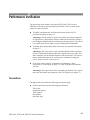
Display and Power Controls
The Side Menu buttons provide
access to side menu selections.
Refer to page 2–7 for more
information about the user interface
Side Menu.
The CLEAR MENU button clears
all menus from the screen.
The ON/STBY button toggles
instrument power.
The Main Menu buttons provide access to
main menu selections. Refer to page 2–7
for more information about the user interface
Main Menu.
TDS 340A, TDS 360 & TDS 380 Technical Reference
2–1
Operating Information
Vertical Controls
The Vertical POSITION knob controls
the vertical position of the selected
waveform.
The Waveform Select buttons display
and select waveforms (CH1, CH2, MATH,
REF1, and REF2). A light next to a button
illuminates when that waveform is
selected.
The VERTICAL MENU button calls up
the vertical operations menu.
Connector to chassis ground.
The SCALE knob controls the vertical
scale of the selected waveform.
Probe compensation output.
The WAVEFORM OFF button turns
off the selected waveform.
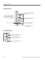
Horizontal Controls
The Horizontal POSITION knob controls
the horizontal position of all waveforms.
The HORIZONTAL MENU button calls up
the horizontal operations menu.
The SCALE knob controls the horizontal
scale of the active waveforms.
2–2
TDS 340A, TDS 360 & TDS 380 Technical Reference
Operating Information
Trigger Controls
The Trigger LEVEL knob controls the
trigger.
The TRIGGER MENU button calls up
the trigger menu.
The SET LEVEL TO 50% button sets the
trigger level at the midpoint between the
peaks of the trigger signal.
The trigger status lights indicate the
status of the triggering system. The
TRIG’D light illuminates when the
instrument recognizes a valid trigger.
The FORCE TRIGGER button forces the
oscilloscope to start acquiring a waveform
regardless of whether a trigger event
occurs. This button has no effect if the
acquisition system is stopped.
The READY light illuminates when the
instrument can accept a valid trigger
and is waiting for that event to occur.
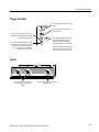
Inputs
The channel BNC inputs (CH1 and
CH2) accept electrical signals for
display.
The EXT TRIG input accepts external
trigger signals.
TDS 340A, TDS 360 & TDS 380 Technical Reference
2–3
Operating Information
Miscellaneous Controls
The MEASURE button calls up the
automated measurements menu.
The UTILITY button calls up the
utility menu.
The AUTOSET button automatically
sets up the instrument to produce a
usable display of the input signals.
The General Purpose Knob controls many
side-menu functions, including the cursors.
The SELECT button switches control from
cursor to cursor.
The floppy disk drive provides
mass storage for waveforms,
setups, and hard copies.
The RUN/STOP button starts
and stops acquisition.
The HARDCOPY button starts
print operations.
(Requires Opt 14 installed)
The ACQUIRE button calls up the
acquisition menu.
The SAVE/RECALL button calls up the
save/recall menu.
The CURSOR button calls up the
cursor menu.
The DISPLAY button calls up the
display menu.
2–4
TDS 340A, TDS 360 & TDS 380 Technical Reference
Operating Information
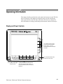
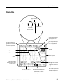
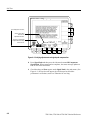
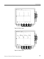
Display Map
Trigger position (T).
Indicates position
of vertical bar
cursors in the
waveform record.
The waveform
record icon.
Shows what part of the waveform record is displayed.
The value entered with the
general purpose knob.
When the general purpose
knob is first assigned, the
knob icon appears here.
The Status Readouts show
trigger status and acquisition
status (mode and sampling rate
or number of acquisitions).
Cursor measurement
readouts.
Trigger level indicator
Trigger point indicator
The side menu offers a
choice of specific
actions.
Channel ground
indicator
The Channel readout
shows the vertical scale of
all active channels.
The Trigger readout shows
the trigger source and level
and whether the oscilloscope
is triggered on the rising or
falling edge of the waveform.
The main menu offers a
choice of major actions.
TDS 340A, TDS 360 & TDS 380 Technical Reference
The Time base readout shows the
time base setting. M indicates
(M)ain time base, D indicates
(D)elayed time base.
When in video-trigger mode,
the readout displays source
and trigger feature (Field 1,
Field 2, or Lines).
2–5
Operating Information
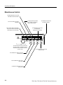
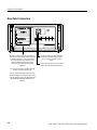
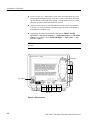
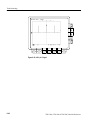
Rear-Panel Connectors
The Option 14 Panel (Option 14 instruments only)
allows access to three communications interfaces:
a Centronics parallel port, an RS-232 interface,
and a GPIB interface. It also includes a VGA
video-compatible output port and a power
connector for the optional TDS4F5P printer
upgrade kit.
The power connector accepts line voltage
to power the instrument. Refer to page 7–2
for a list of power cord and connector
options.
The fuse drawer holds the line fuse. Refer to
page 6–8 for fuse replacement procedures.
You can use the Centronics, RS-232, and GPIB
interfaces to transmit hardcopy data.
You can use the GPIB and RS-232 interfaces to
operate and program the oscilloscope from a GPIB
or RS-232 controller; refer to the TDS 340A, TDS
360 & TDS 380 Programmer Manual for more
information.
2–6
TDS 340A, TDS 360 & TDS 380 Technical Reference
Operating Information
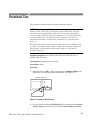
Using the Menu System
TDS 300 Series oscilloscopes use an intuitive user interface. This interface
reduces front-panel clutter while allowing easy access to specialized functions
through the menu structure.
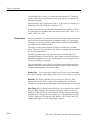
The following procedure describes how to navigate in the menu structure. If you
are unfamiliar with this menu system, you may want to run through the
procedure several times to learn how you can access functions and subfunctions.
Figure 2–2 provides a graphic overview of using the menu system.
TDS 340A, TDS 360 & TDS 380 Technical Reference
2–7
Operating Information
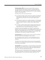
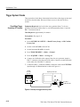
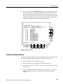
1. Push a front-panel button to call up a menu of functions. This first menu is
the main menu. Sometimes the main menu will be a side menu (step 3), but
most main menus are bottom menus.
2. Push a main menu button to select a function. One of three things happens:
If the function has no subfunctions, it becomes active. If it is a variable
function, you can now use the General Purpose Knob to adjust it
(step 4).
If the function has subfunctions, they appear on the side menu (step 3).
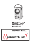
The leftmost main menu button sometimes activates a pop-up menu (as
shown in Figure 2–1). You can cycle through the pop-up menu options
by repeatedly pressing the button. Each selection calls up different main
and side menus.
Figure 2–1: A pop-up menu
3. Push a side-menu button to select a subfunction.
4. Use the General Purpose knob to change variable-function or subfunction
settings.
5. Press the CLEAR MENU button to remove a menu from the screen.
2–8
TDS 340A, TDS 360 & TDS 380 Technical Reference
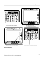
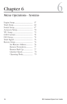
Operating Information
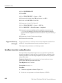
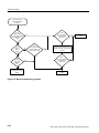
1 Press any of the front-panel menu buttons.
2 Select an item from the main menu
or use leftmost button to pop up selections.
3 Select an item from the side menu, if displayed.
4 Adjust menu item values with general purpose knob.
Figure 2–2: Using menus
TDS 340A, TDS 360 & TDS 380 Technical Reference
2–9
Operating Information
2–10
TDS 340A, TDS 360 & TDS 380 Technical Reference
Theory of Operation
This chapter describes the electrical operation of the TDS 340A, TDS 360, and
TDS 380 at the module level.
Logic Conventions
This manual refers to digital logic circuits with standard logic symbols and
terms. Unless otherwise stated, all logic functions are described using the
positive logic convention: the more positive of the two logic levels is the high
(1) state and the more negative level is the low (0) state. Signal states may also
be described as “true” meaning their active state or “false” meaning their
non-active state. The specific voltages that constitute a high or low state vary
among the electronic devices.
Active-low signals are indicated by a tilde (~) prefixed to the signal name
(~RESET). Signal names are considered to be either active-high, active-low, or
to have both active-high and active-low states.
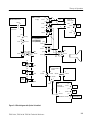
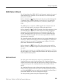
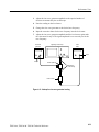
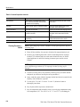
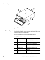
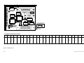
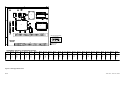
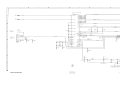
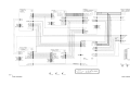
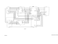
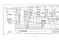
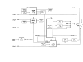
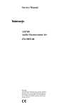
Module-Level Overview
This overview describes the basic operation of each circuit module as shown in
Figures 3–1 through 3–2.
Input Signal Path
A signal enters the oscilloscope through a probe connected to a BNC on the A11
(TDS 340A), A12 (TDS 360), or A13 (TDS 380) Main Board.
Attenuators. Circuitry in the attenuator selects the input coupling and attenuation
factor. The processor system controls the attenuators with a serial interface.
Probe Coding Interface. The probe coding interface signals pass through the Main
Board to the A6 Front Panel, which senses them.
Acquisition System. The acquisition system amplifies the input signals, samples
them, converts them to digital signals, and controls the acquisition process under
direction of the processor system. The acquisition system includes the trigger,
acquisition timing, and acquisition mode generation and control circuitry.
TDS 340A, TDS 360 & TDS 380 Technical Reference
3–1
Theory of Operation
A20 LV Power
A9 Bezel Button Flex
Supply
10 Pins
P1
A6
Front Panel
J2
P2
2 Pins
J40
10 Pins
J3
P3
J1
13 Pins
P1
2
Fan
2 Pins
J35
4 Pins
13
Cal Sig
J84
5 Pins
Not Used
J30
16 Pins
P30
P603
16
2
A11 (TDS 340A) Main
A12 (TDS 360)
A13 (TDS 380)
J702
13 Pins
J603
16 Pins
A26 Monitor
J901
J702
8 Pins
10 Pins
8
J53
CH1
J605
A5 Floppy interface
J52
Floppy disk drive
board
CH2
J602
J606
50 Pins
JR3
50 Pins
J1
26 Pins
J1
26
26 Pins
J51
EXT
TRIG
J607
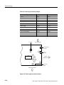
Figure 3–1: Block diagram
3–2
TDS 340A, TDS 360 & TDS 380 Technical Reference
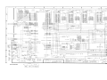
Theory of Operation
J2
A20 LV Power
Supply
A9 Bezel Button Flex
P2
2 Pins
J4
10 Pins
P1
A6
Printer Power
J1
2
2 Pins
J40
10 Pins
A3 Option 14
Fan
P4
P3
J3
Front Panel
2
J4
6
2 Pins
2 Pins
2 Pins
PWR
6 Pins
J3
P1
J1
13 Pins
J2
VGA
9 Pins
J35
4 Pins
13
Cal Sig
J84
5 Pins
Not Used
2
A11 (TDS340A) Main
A12 (TDS 360)
A13 (TDS 380) J702
13 Pins
J703
P703
A26 Monitor
6 Pins
P30
J30
16 Pins
P603
16
J603
16 Pins
J901
J701
8 Pins
10 Pins
8
J53
CH1
J605
A5 Floppy interface
J52
Floppy disk drive
board
CH2
J601
J606
50 Pins
JR3
J1
50 Pins
26
26 Pins
26 Pins
J2 50 Pins
J51
EXT
TRIG
J607
P601
A2
Option 14
I/O Interfaces
J2
9 Pins
RS232
J4
50
J1
50 Pins
25 Pins
GPIB
J3
50 Terminations 25 Pins
CENTRONICS
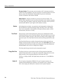
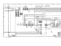
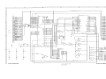
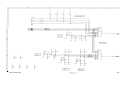
Figure 3–2: Block diagram with Option 14 installed
TDS 340A, TDS 360 & TDS 380 Technical Reference
3–3
Theory of Operation
Processor System. The processor system contains a 68331 microprocessor that
controls the entire instrument. The processor passes waveforms and text on to the
display system. The Main Board contains both the processor and display
systems, in addition to the firmware ROMs.
Display System. A display controller IC processes text and waveforms. The
display system sends the text and waveform information to the monitor assembly
as a video signal. The display system also generates and sends vertical (VSYNC)
and horizontal (HSYNC) sync signals to the monitor assembly.
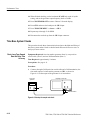
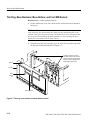
Monitor
Front Panel
All information (waveforms, text, graticules, and pictographs) is displayed by
the A26 Monitor. It generates the high voltages necessary to drive the display
tube. It also contains the video amplifier, horizontal oscillator, and the vertical
and horizontal yoke driver circuitry.
The processor system sends instructions to and receives information from the
Front Panel Processor on the Front Panel Board. The Front Panel Processor reads
the front-panel switches and ports, and reports any change in their settings to the
processor system. The Front Panel Processor also turns front panel LEDs on and
off.
The Front Panel Processor reads the front-panel menu switches and sends any
changes in menu selections to the processor system. The ON/STBY button is not
read by the Front Panel Processor but passes through the Front Panel Board and
the Main Board to the A20 Low Voltage Power Supply.
The front panel also generates the probe compensation signal.
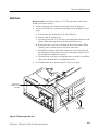
Floppy Disk Drive
The floppy disk drive system consists of the A5 floppy interface board that
connects to the main board. A 26-pin cable connects the floppy disk drive to the
floppy interface board, supplying both power and data to the drive.
The drive is 2 Mbyte double-side, high-density unit that uses 3.5 inch IBM-format disks.
Option 14
3–4
The A2 Option 14 board has GPIB, RS-232, and Centronics interfaces for
external control and hardcopy operations. Also included is the A3 board with a
VGA video output port and a power connector for the Option 3P printer.
TDS 340A, TDS 360 & TDS 380 Technical Reference
Theory of Operation
Low Voltage Power Supply
The A20 Low Voltage Power Supply is a switching power converter. It supplies
power to all the circuitry in the oscilloscope.
The Low Voltage Power Supply does not have a main power switch. The
ON/STBY switch, located on the front panel, controls all the power to the
oscilloscope except the standby circuits in the Low Voltage Power Supply.
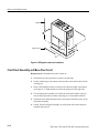
Fan
The fan provides forced air cooling for the oscilloscope. It connects to a 12 V
connector on the Low Voltage Power Supply.
TDS 340A, TDS 360 & TDS 380 Technical Reference
3–5
Theory of Operation
3–6
TDS 340A, TDS 360 & TDS 380 Technical Reference
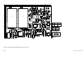
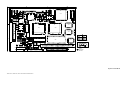
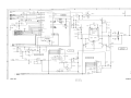
Component-Level Overview
This section describes the electrical operation of the oscilloscope. Refer to the
schematics in the Diagrams section as necessary.
A11/A12/A13 Main Board
A signal enters the oscilloscope through a probe connected to a BNC on the A11
(TDS 340A), A12 (TDS 360), or A13 (TDS380) Main Board.
Attenuators. Circuitry in the attenuator selects the input coupling and attenuation
factor. The processor system controls the attenuators with a serial interface as
well as through voltage changes with the daculator.
The Main Board assembly contains two attenuator hybrids, six relay drivers, and
two probe connectors. Each attenuator hybrid contains resistive dividers, an AC
coupling capacitor, three relays and a preamplifier. The AC/DC coupling relay
couples the output of the BNC to the other relays in the attenuator hybrid. For
AC signals, the AC/DC coupling relay inserts a coupling capacitor into the input
signal path. The second relay generates a calibration or ground signal. The third
relay selects the attenuation factor (X1, X10, or X100).
Probe Code Interface. The probe coding interface signals pass through the Main
Board to the A6 Front Panel, which converts the probe code voltage to a digital
value.
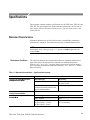
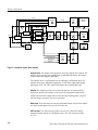
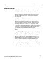
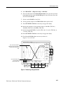
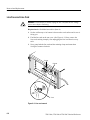
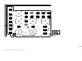
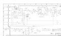
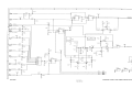
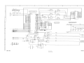
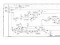
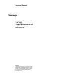
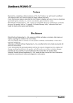
Acquisition System. The acquisition system amplifies the input signals, samples
them, converts them to digital signals, and controls the acquisition process under
direction of the processor system. The acquisition system includes the trigger,
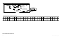
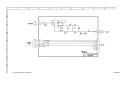
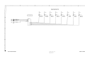
acquisition timing, and acquisition control circuitry. Figure 3–3 shows a block
diagram of the acquisition system.
The sampler driver (U204) amplifies and acquires the analog signal supplied by
the attenuators. The acquisition system converts the signal to digital and stores it
in acquisition memory. The time base controller controls the acquisition process.
The CPU monitors and controls the overall system, and transfers the acquired
waveform to the display system.
Daculator. The daculator system provides DC voltage signals that set the offsets
and variable gain control voltages for the attenuator hybrids and trigger levels.
The CPU controls the daculator serially.
TDS 340A, TDS 360 & TDS 380 Technical Reference
3–7
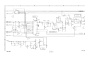
Theory of Operation
#&
!!+ ,
#&
!!+ ,
*#$
,, &-,'*
,, &-,'*
%($#!# *
%($#!# *
(,#'&
'*+
%($ * *#. *
-$,'*
-+
%($ *
-!! *
%(
#% +
'&,*'$$ *
#%
&, *('$,'*
*'
'#&"
/, *&$ *#"" *
&$'"
*#"" *
*#"" *
'"#
/, *#"
)-#+#,#'&
%'*0
#+($0
#&
Figure 3–3: Aquisition system block diagram
Sampler Driver. The output of the attenuator drives the sampler driver inputs. The
sampler driver provides gain amplification, bandwidth limit filters, and outputs
for the sampler and trigger signal paths.
The sampler driver is an integrated circuit containing a differential input. The
sampler driver has a differential signal gain of 14X and a single-ended trigger
signal gain of 2X. The CPU controls the sampler driver bandwidth limit.
Sampler. The sampler provides two acquisition channels. It contains analog
acquisition memory and a heater circuit to provide temperature stabilization.
START/STOP tells the sampler when to start and stop acquiring data. ACQINIT
tells the sampler to prepare for a new acquisition.
Buffer Amp. The buffer amp converts the differential output signal of the sampler
to a single ended signal for use by the A/D converter.
A/D Converter. The A/D converter (U403) converts CH 1 and CH 2 analog
samples from the sampler to 8 bit digital values. The A/D reference voltage
is 1.0 V.
3–8
TDS 340A, TDS 360 & TDS 380 Technical Reference
Theory of Operation
Time Base Controller (TBC). The time base controller (TBC) provides the
horizontal acquisition control for the oscilloscope. It counts pretrigger and
posttrigger samples and writes data points into acquisition memory. Programming and control of the sampler is through the TBC. CPU access to acquisition
memory is also through the TBC.
The TBC operates in three basic acquisition modes.
In Fast mode the sampler acquires and stores the complete record internally.
When stopped, the analog data can be read out, digitized, and moved into
acquisition memory. This process is based on the 60.6 MHz oscillator
(Y401).
In Slow mode, the sampler acts as a sample and hold device. The data points
are transferred point by point to be digitized and stored in acquisition RAM
as they are acquired. This process is based on the 40.0 MHz oscillator
(Y402).
In Peak Detect mode the sampler holds the minimum and maximum values
over a sample interval. The data points are transferred point by point to be
digitized and stored in the acquisition RAM as they are acquired.
The processor initiates the acquisition. Once ACQINIT is released and the
pretrigger count is satisfied, EPTHO (end of pretrigger holdoff) is asserted to the
trigger logic. Once the trigger logic receives the EPTHO, it will accept triggers.
A trigger from SYNTRIG A will start the posttrigger counter in the TBC. Once
the posttrigger count is finished, the sampler will be stopped.
Acquisition Memory. The acquisition memory consists of an 8K-by-8K SRAM.
The CPU reads this memory through the time base controller.
The time interpolator counter in the TBC counts for the duration of the slow
ramp and terminates the count when it receives COUNTSTOP from the time
interpolator.
The holdoff counter holds off trigger from being accepted for a programmable
period of time. It is asynchronous to the FAST system clock. HOLDOFF begins
on MAT (main accepted trigger).
Time Interpolator. The Time Interpolator is a dual-ramp timing circuit that detects
and measures the time difference between a trigger event and the sample clock.
The CPU uses this time to correctly place the data points obtained on different
trigger events. The TBC contains the ramp counters.
The dual ramp consists of a short-duration, positive-going ramp and a long-duration, negative-going ramp. The ramps are the result of charging or discharging
integrating capacitors C307 and C305 from constant current sources. The
TDS 340A, TDS 360 & TDS 380 Technical Reference
3–9
Theory of Operation
charging and discharging currents are available at the collectors of Q304 and
Q305, respectively. The ratio of these currents is about 2000 to 1.
The trigger event initiates the charging ramp. The next occurrence of the system
clock disconnects the charging current, initiating the discharging ramp.
The baseline regulator circuit maintains the voltage at the collector of Q307 at 0
V while waiting for a trigger. When this node is at 0 V, the COUNTSTOP signal,
at the output of U304A, is low.
When U308B detects a trigger event at its input it sets ~RSTM to the “true” state,
which begins the fast ramp. Q307 is turned off so that the fast ramp charging
current will begin to charge the integration capacitors.
The constant current source, Q304 and associated components, determines the
fast charging rate. The charging current is nominally 22 mA through R302 and
Q304. This current flows through Q301 during the fast ramp charging time and
through Q302 during the slow ramp discharge time.
This fast ramp charging, initiated by the trigger event, will end when the next
system clock occurs. This causes the trigger logic (U309) to generate the
~RMSW and RMSW signals, to switch from fast-ramp charge to slow-ramp
discharge, and tells the TBC (U401) to start counting the ramp discharge time.
Q301 is now turned off (and Q302 turned on) to disconnect the 22 mA current
source from the integrating capacitors. Now the integrating capacitor discharges
through the 11 A current source formed by Q305 and associated components.
When the ramp crosses a –100 mV threshold, the COUNTSTOP signal goes
high, causing the TBC to stop the counting. This count represents the time from
trigger event until the next system clock. The circuitry reads the time base
interpolator counter, and then is reset by the next ACQINIT.
The signals ~RMST, RMST, ~RMSW, and RMSW are positive referenced ECL
levels. The COUNTSTOP signal has TTL levels.
Analog Trigger. The analog trigger is a free running analog comparator. It has a
variable input threshold determined by the TLM (trigger level).
The input has a channel switch. Control signals SR1, SR2, and SR3 select one of
five input signals. The channel switch output is at TP102. Probing this can
indicate whether or not the channel switch is working.
Once the source has been selected, filters can be applied to the signal. Filters
include high frequency reject, low frequency reject, DC coupled, AC coupled,
noise reject and AC noise reject.
Next, the signal is compared to a reference threshold (i.e., trigger level). The
polarity of the comparator can be switched to change the trigger slope. A shift
register controls filter selection, slope selection, and mode selection. The trigger
3–10
TDS 340A, TDS 360 & TDS 380 Technical Reference
Theory of Operation
control clock (CC) and the control data (SDATA_OUT) control this shift register.
Bit 7 is clocked in first, and bit 0 is clocked in last.
The output of the analog trigger is a differential pair of +5 V referenced ECL
signals. Output pins 20 and 21 swing full ECL levels, terminated at 75 W into
the trigger logic.
Trigger Logic. Trigger logic is the digital part of the trigger system. It is composed of discrete positive referenced ECL logic. Trigger logic performs the
following functions:
CPU System
It selects the trigger event. The CPU serially selects analog trigger
(TRIG_GATE), field 1, field 2 (TV_FIELDS), any field (ANY_FIELD), or
lines (CSYNC). The different modes are dependent on trigger related
front-panel settings.
It accepts all trigger events and decides which event will finish the acquisition. The analog holdoff qualifies the main trigger event to become the main
used trigger.
The CPU system contains a 68331 microprocessor that controls the entire
instrument. The processor passes waveforms and text on to the display system.
The Main Board contains both the CPU and display systems, and the firmware
ROMs.
The CPU coordinates all oscilloscope activities. It also directs the activities of
the front-panel processor using a serial interface.
CPU Clocks. Processor clocks are derived from 60.6 MHz oscillator Y401. The
TBC divides the 60.6 MHz clock by 4 for a PROC_CLK of 15.15 MHz.
Interrupts. The 68331 supports seven levels of auto-vectored interrupts dedicated
to different interrupt levels. The TBC, display system, and option board generate
interrupts.
Reset. The CPU resets both at power-on and power-off using the reset signal.
Reset controller U606 controls system reset. Power-on reset asserts for a
minimum of 400 ms after the +5 V supply stabilizes. Power-off reset asserts
when the supply falls below a usable threshold.
Memory. The memory subsystem includes 32 K 8 NVRAM for power-off
storage and dynamic RAM for the main system RAM.
TDS 340A, TDS 360 & TDS 380 Technical Reference
3–11
Theory of Operation
The NVRAM (U605) consists of a single nonvolatile memory IC. This RAM
provides long-term power-off storage of front-panel settings, waveforms, and
calibration constants.
Dynamic RAM U704 is organized as 256 K 16 for a total of 512 kbytes. It is
controlled by the ADG250 display controller (U701).
During a normal 68331 access the ADG250 multiplexes the address (on A2 to
A19) onto the A0 to A8 address lines and creates control signals ~RAS, ~CAS,
~XWL, ~XWU, and ~XOE.
Display System
A display controller IC processes text and waveforms. The display system sends
the text and waveform information to the monitor assembly as a video signal.
The display system also generates vertical (VSYNC) and horizontal (HSYNC)
sync signals for the monitor assembly.
The display circuit’s primary function is writing waveforms into waveform
planes. The circuitry provides Vector, Dot, Vector Accumulate, Dot Accumulate,
XY, and YT display modes.
The display system provides text, graticule, and waveform bit planes. All
information displayed is first written to a plane. Planes are stored in dedicated
DRAMS along with the vector lists. The information is sent at regular refresh
intervals as an analog video signal.
The waveform display circuit takes a list of sample points, translates them into
intensities for the bit map, writes those intensities to the bit map in the proper
location, and interrupts the CPU when it is done.
— Four vector lists available from U706 store waveform sample
data. Before starting a normal display mode, the CPU writes data to a vector list.
Rasterizers. The display controller (U701) provides two rasterizers. Their
primary function is to “draw” vectors between sample points. The display
controller also performs the top and bottom clip display functions on waveforms.
Video Timing. Q701–Q704 and associated circuitry convert digital video signals
from the display controller into an analog video signal, with two levels controlled by VIDEO LEVEL and INTENS LEVEL from the daculator. The display
controller also creates monitor timing HSYNC (31.25 Hz) and VSYNC (60 Hz).
U703D, U708D, and U709 generate AUX HSYNC, AUX VSYNC and AUX
VIDEO for the Option 14 VGA Video output connector.
3–12
TDS 340A, TDS 360 & TDS 380 Technical Reference
Theory of Operation
A2/A3 Option 14 Board
The A2 Option Board has GPIB, RS-232, and Centronics interfaces for external
control and hard copy operations. The A3 board has VGA Video output and
printer power interfaces.
Refer to schematic A2 . Signals travel from the processor board through the
J1 connector to the U2 address decoder. U2 uses lines A15, A16, and A18 to
break incoming addresses to either the RS-232, Centronics, GPIB or option
ROM.
The GPIB circuitry is composed of GPIB controller U8, with transceivers U9
and U10 buffering signals to and from the GPIB on the option board.
Refer to schematic A2 . The RS-232 portion of the board connects to the rear
panel through port J2. Signals travel from the processor board through the J1
connector to the U4 dual asynchronous receiver/transmitter (DUART). The
DUART sends data to the U5 driver/receiver. U5 converts signals from logic
levels on the DUART side to RS-232 levels at the 9-pin connector. From U5,
information goes out port P2.
The Centronics portion of the board connects to the rear panel through the 9-pin
connector J3. Data travels from the processor board through the J1 connector to
register U6 where it is sent out J3. U4 manages control signals. U12 buffers
printer status information to be read through U4.
Refer to schematic A3 . The 9-pin VGA video connector routes auxiliary
HSYNC, VSYNC, and VIDEO signals from main board connector J703 to the
rear panel.
The printer power converter uses switching regulator U1 to convert +15 V from
the power supply to +8 V output at rear panel connector J2. This provides power
for the Option 3P thermal printer.
A6 Front Panel
The CPU system sends instructions to and receives information from the
Front-Panel Processor on the Front-Panel Board. The Front-Panel Processor
reads the front-panel switches and ports, and reports any change in their settings
to the processor system. The Front-Panel Processor also turns the LEDs on
and off.
The Front-Panel Processor reads the front-panel menu switches and sends any
changes in menu selections to the CPU system. The Front Panel Processor does
not read the ON/STBY button; its signal passes through the Front-Panel Board
and the Main Board to the A20 Low Voltage Power Supply.
The front panel also generates the probe compensation signal.
TDS 340A, TDS 360 & TDS 380 Technical Reference
3–13
Theory of Operation
Pots, FPP, and Calibrator. The front-panel processor monitors the front-panel
controls. It consists of a single-chip microprocessor (U101) with built-in RAM,
ROM, A-to-D converter (for digitizing the potentiometer wiper voltages), a
programmable timer (for generating the output of the probe compensator signal),
and a serial communications interface (for data transfer to and from the CPU).
The knob scanner, working with the A-to-D converter internal to the front-panel
processor, produces digital values for the wiper voltages of the front-panel
knobs. Analog multiplexers U420 and U421 select one of 12 possible pot inputs
to read. Although there are only six knobs on the front panel, three are continuous-rotation potentiometers made up of two wipers, separated by 180 degrees,
which contact a single resistive arc.
Three control lines to multiplexers U420 and U421 select the pot input or wiper
voltage to be read. The analog voltage at the wiper of the pot selected is applied
to the front-panel processor. This voltage is digitized, and the amount and
direction of change from the previously stored value is calculated. The change
information is sent to the CPU.
The front-panel processor generates CALSIG. The high level is ≈5 V and the low
level is at ground.
Switches. The front-panel switches and menu switches are arranged in an array of
eight rows and columns. When a switch closes, one row line connects to one
column line through an isolation diode. A complete scan of the front-panel
switches consists of setting all eight row lines low, in sequence, and performing
an eight-column scan to check for a change from the state stored in the front-panel processor. Low bits in the column-line data tell the front-panel processor that a
switch is closed.
LEDs and Power Supply. The LEDs are arranged in groups of eight. They are
connected between the outputs of 8-bit LED latch (U202). When the CPU needs
to turn a particular LED on or off, it sends a command to the front-panel
processor indicating what to do to the LED, and which one to change. The
front-panel processor converts the LED identification number to the LED
address within the latch.
A20 Low Voltage Power Supply
The A20 Low Voltage Power Supply is a switching power converter. It supplies
power to all the circuitry in the oscilloscope.
The Low Voltage Power Supply does not have a main power switch. The
ON/STBY switch, located on the front panel, controls all the power to the
oscilloscope except the standby circuits in the Low Voltage Power Supply.
3–14
TDS 340A, TDS 360 & TDS 380 Technical Reference
Theory of Operation
A26 Monitor Assembly
The A26 Monitor Assembly displays all information (waveforms, text, graticules, and pictographs). It generates the high voltages necessary to drive the
display tube. It also contains the video amplifier, horizontal oscillator, and the
vertical and horizontal yoke driver circuitry.
The 640 by 480 pixel raster scan cathode-ray tube (CRT) display has 60 Hz
frame and 31.5 kHz line rates. This CRT display circuitry is similar to a
television monitor.
Inputs, Video, and Vertical Deflection. The +12 V regulator is a three-terminal
regulator (U130).
The Vertical Yoke Winding Driver provides the scan current (ramp) for the
vertical (field) deflection coil. A vertical sync signal, a negative pulse at the
deflection rate, causes the ramp to “retrace” to the top of the CRT screen.
A large pulse is generated during vertical retrace. A portion of this signal drives
the G1 grid 50 V more negative than normal during the retrace period. This
keeps retrace lines blanked even when the background is visible.
The Video Amplifier amplifies the input video signal, and drives the cathode of
the CRT.
Horizontal Deflection, CRT, and High Voltage. The Horizontal Oscillator Control
generates the “switch” controlling signal and synchronizes the scan to the
horizontal sync input signal. IC U370 includes a horizontal oscillator, a phase
detector, and an output shaper
The circuit is a phase-locked loop. The differentiated horizontal sync is the
reference signal, and the retrace or flyback pulse (U370 pin 4) is the feedback
signal to be locked to the horizontal sync (HORIZONTAL YOKE) signal.
Horiz Yoke Winding Driver transistor Q160, along with Q260 and T170,
provides the deflection coil currents.
Transformer T210 generates the CRT high voltage from the large voltage pulse
that occurs during horizontal retrace (flyback pulse). Other secondary voltages
are also derived from the flyback pulse.
TDS 340A, TDS 360 & TDS 380 Technical Reference
3–15
Theory of Operation
3–16
TDS 340A, TDS 360 & TDS 380 Technical Reference
Performance Verification
The procedures in this chapter verify that the TDS 340A, TDS 360, and
TDS 380 oscilloscopes meet warranted specifications. There are three performance tests that you can do.
To rapidly confirm that this oscilloscope functions, do the Self Test
procedures that begin on page 4–5.
Advantages: This procedure is quick to do, requires no external equipment
or signal sources, and performs extensive functional and accuracy testing to
provide high confidence that the oscilloscope performs properly. You can use
it as a quick check before making a series of important measurements.
To further check functionality, do the Functional Test procedures that begin
on page 4–7.
Advantages: These procedures require minimal additional time to perform,
require no additional equipment other than a standard-accessory probe, and
more completely test the internal hardware of this oscilloscope. You can use
them to quickly determine if the oscilloscope is suitable for putting into
service, such as when it is first received.
If you need a more extensive confirmation of performance, do the
Performance Tests that begin on page 4–11, after doing the functional and
self tests.
Advantages: These procedures check warranted specifications. They require
more time and suitable test equipment. (See Test Equipment on page 4–3.)
Conventions
Throughout these procedures the following conventions apply:
Each test procedure uses the following general format:
Title of test
Equipment required
Time required
Prerequisites
Procedure steps
TDS 340A, TDS 360 & TDS 380 Technical Reference
4–1
Performance Verification
Refer to Figure 4–1: “Main menu” refers to the menu that labels the seven
menu buttons under the display. “Side menu” refers to the menu that labels
the five buttons to the right of the display. “Pop-up menu” refers to a menu
that pops up when a main menu button is pressed.
Where instructed to use a front-panel button or knob, select from a main or
side menu, or verify a readout or status message, the name of the button or
knob appears in boldface type.
Instructions for menu selection follow this format: FRONT PANEL
BUTTON ! Pop-Up (if necessary) ! Main Menu Button ! Side Menu
Button. For example, “Push TRIGGER MENU ! Type: Video ! Trigger On ! Lines.”
STOP. This symbol denotes information you must read to do the procedure
properly.
Side Menu
Pop-Up Menu
Main Menu
Figure 4–1: Menu locations
4–2
TDS 340A, TDS 360 & TDS 380 Technical Reference
Performance Verification
Test Equipment
The performance test procedures require external, traceable signal sources to
check instrument performance. If your test equipment does not meet the
minimum requirements listed in Table 4–1, your test results will be invalid.
Table 4–1: Test equipment
Item number
and description
Minimum requirements
Example
Purpose
1.
Termination 50 W
(two required)
Impedance 50 W; connectors:
female BNC input, male BNC
output
Tektronix part number
011-0049-01
Checking delay between
channels
2.
Cable, Precision Coaxial
(two required)
50 W, 91 cm (36 in), male to
male BNC connectors
Tektronix part number
012-0482-00
Signal interconnection
3.
Connector,
Dual-Banana
Female-BNC to dual-banana
Tektronix part number
103-0090-00
Several accuracy tests
4.
Connector,
BNC “T”
Male-BNC to dual-female-BNC
Tektronix part number
103-0030-00
Checking trigger sensitivity
5.
Coupler,
Dual-Input
Female-BNC to dual-male-BNC
Tektronix part number
067-0525-02
Checking delay between
channels
6.
Generator, DC Calibration
Variable amplitude to ±110 V;
accuracy to 0.1%
Wavetek 9100 Calibration
System with Option 250
Checking DC offset, gain, and
measurement accuracy
7.
Generator,
Leveled Sine Wave,
Medium-Frequency
200 kHz to 250 MHz; variable
amplitude from 5 mV to 4 Vp-p
into 50 W
Wavetek 9100 Calibration
System with Option 250
Checking bandwidth and trigger
sensitivity
8.
Generator,
Leveled Sine Wave,
High-Frequency1
200 kHz to 400 MHz; variable
amplitude from 5 mV to 4 Vp-p
into 50 W
Rohde & Schwarz SMY with
URV 35 Power Meter and
NRV-Z8 Power Sensor
Checking bandwidth and trigger
sensitivity
9.
Generator, Time Mark
Variable marker frequency from
10 ms to 10 ns; accuracy within
2 ppm
Wavetek 9100 Calibration
System with Option 250
Checking sample rate and
delay-time accuracy
A P6109B (TDS 340A), P6111B
(TDS 360), or P6114B
(TDS 380) probe
Tektronix number
P6109B (TDS 340A), P6111B
(TDS 360), or P6114B
(TDS 380)
Signal interconnection
10. Probe, 10X,
included with this
instrument
1
The high frequency leveled sine wave generator is only required to verify the TDS 380, not the TDS 340A or TDS 360. If
you use the example equipment, refer to Sine Wave Generator Leveling Procedure on page 4–20 for information on
obtaining a leveled output from an unleveled sine wave generator. If available, you can use a Tektronix SG504 Leveled
Sine Wave Generator in place of the example equipment.
TDS 340A, TDS 360 & TDS 380 Technical Reference
4–3
Performance Verification
Test Record
Photocopy this page and use it to record the performance test results for your
instrument.
TDS 340A, TDS 360, and TDS 380 test record
Instrument Serial Number:
Temperature:
Date of Calibration:
Certificate Number:
RH %:
Technician:
Performance test
Minimum
Incoming
Outgoing
Maximum
200 mV
50 mV1
50 mV2
D at 50 mV
10 mV
5 mV
+97.1 V
+8.28 V
–581 mV
–881 mV
+286 mV
+54.6 mV
–982 mV
__________
__________
__________
__________
__________
__________
__________
__________
__________
__________
__________
__________
__________
__________
+98.9 V
+8.52 V
–619 mV
–919 mV
+314 mV
+65.4 mV
–998 mV
CH1
42.5 mV
__________
__________
N/A
CH2
42.5 mV
__________
__________
N/A
–2.0 Div
__________
__________
+2.0 Div
stable trigger
stable trigger
__________
__________
__________
__________
N/A
N/A
DC Voltage Measurement Accuracy
CH1 VOLTS/DIV
CH2 VOLTS/DIV
1V
1V
Analog bandwidth
Long term sample rate and delay time accuracy
Edge trigger sensitivity, DC coupled
Main Trigger
Main Trigger – Falling
1
2
4–4
Generator set at –0.6 V.
Generator set at –0.9 V.
TDS 340A, TDS 360 & TDS 380 Technical Reference
Self Test
This procedure uses internal routines to verify that the oscilloscope functions and
passes its internal self tests and signal-path compensations. It also confirms that
the oscilloscope was adjusted properly at the time it was last adjusted. No test
equipment or hookups are required.
Equipment Required: None.
Time Required: Approximately 5 minutes.
Prerequisites: Power up the oscilloscope and allow a 20 minute warm up before
doing this procedure.
Procedure:
1. Press the front-panel button UTILITY.
2. Press the main-menu button System to select Diag.
3. Press the main-menu button Execute and then press the side-menu button
OK Confirm Run Test. The internal diagnostics verify proper oscilloscope
function. This verification takes about 30 seconds. While it progresses, a
variety of test patterns flash on screen. When finished, status messages
appear on the screen.
4. Check that the screen reports no failures. If it reports a failure, the oscilloscope has failed the self test. Contact your Tektronix representative for
assistance.
5. Press CLEAR MENU.
6. Press UTILITY and then press the main-menu button System to select Cal.
7. Check that the word Pass appears in the main menu under the Voltage
Reference, Timing, and Ext Trig menu labels. (See Figure 4–2.) If any of the
labels read Fail, the oscilloscope has failed the self test. Contact your
Tektronix representative for assistance.
TDS 340A, TDS 360 & TDS 380 Technical Reference
4–5
Self Test
First, display the Cal menu.
Second, verify Pass
status for the
adjustment sections.
Third, run a signal path
compensation and verify
status is Pass.
Figure 4–2: Verifying adjustments and signal path compensation
8. Press Signal Path and then press the side menu button OK Compensate
Signal Paths. When compensation completes, the status message updates to
Pass or Fail in the main menu
9. Check that the word Pass appears under Signal Path in the main menu. (See
Figure 4–2.) If Pass does not appear, the oscilloscope has failed the
performance verification; return it to Tektronix for servicing.
4–6
TDS 340A, TDS 360 & TDS 380 Technical Reference
Functional Test
This procedure confirms that the oscilloscope functions properly.
NOTE. This procedure verifies functions; that is, it verifies that oscilloscope
features operate. It does not verify that they operate within limits. Therefore,
when the instructions that follow call for you to verify that a signal appears
on-screen “that is about five divisions in amplitude” or “has a period of about
six horizontal divisions,” do NOT interpret the quantities given as limits.
Operation within limits is checked in the performance tests, which begin on
page 4–11.
DO NOT make changes to the front-panel settings that are not called out in the
procedure. If you make changes to these settings other than those called out in
the procedure, you may obtain invalid results. In this case, just redo the
procedure from step 1.
Equipment Required: One P6109B (TDS 340A), P6111B (TDS 360), or
P6114B (TDS 380) probe.
Time Required: Approximately 5 minutes.
Prerequisites: None.
Procedure:
1. Install the probe on CH 1. Connect the probe tip to PROBE COMP on the
front panel; leave the probe ground unconnected. (See Figure 4–3.)
Digitizing oscilloscope
Figure 4–3: Hookup for functional test
2. Press the front-panel button SAVE/RECALL, the main-menu button Recall
Factory Setup, and then the side-menu button OK Confirm Factory Init.
TDS 340A, TDS 360 & TDS 380 Technical Reference
4–7
Functional Test
3. Press AUTOSET.
4. Set the VOLTS/DIV to 1 V. Use the vertical POSITION knob to center the
waveform vertically on screen.
5. Set the SEC/DIV to 250 ms. Check that a square wave probe-compensation
signal of about five divisions in amplitude is on screen.
6. Check that one period of the square wave probe-compensation signal is
about four horizontal divisions on screen.
7. Check that the horizontal POSITION knob positions the signal left and right
on screen when rotated.
8. Press the front-panel button TRIGGER MENU, the main-menu button
Mode, and then the side-menu button Normal.
9. Check that the trigger-level readout for the main trigger system changes with
the trigger LEVEL knob.
10. Check that the trigger-level knob can trigger and untrigger the square-wave
signal as you rotate it. (Leave the signal untriggered.)
11. Check that pressing SET LEVEL TO 50% triggers the signal that you just
left untriggered.
12. Press the front-panel button ACQUIRE, the main-menu button Mode, and
then the side-menu button Sample.
13. Check that the oscilloscope displays an actively acquiring waveform. (Note
that there is noise present on the peaks of the square wave.)
14. Press the side-menu button Peak Detect. Check that the oscilloscope
displays an actively acquiring waveform with the noise “peak detected.”
15. Press the side-menu button Envelope. Check that the oscilloscope displays
an actively acquiring waveform with the noise displayed.
16. Press the side-menu button Average. Check that the oscilloscope displays an
actively acquiring waveform with the noise reduced.
17. Press WAVEFORM OFF to remove Channel 1 from the display.
18. Press CH 2 and move the probe to the CH 2 input.
19. Repeat steps 3 through 16 for Channel 2.
20. Disconnect the probe from the channel input and the PROBE COMP
terminal.
4–8
TDS 340A, TDS 360 & TDS 380 Technical Reference
Functional Test
File System Functional Test
Equipment Required: One 720K or 1.44Mbyte, 3.5 inch DOS-compatible disk
(formatted).
Time Required: Approximately 5 minutes.
Prerequisites: None.
Procedure:
1. Install the probe on CH 1. Connect the probe tip to PROBE COMP on the
front panel; leave the probe ground unconnected. (See Figure 4–4.)
Digitizing oscilloscope
Figure 4–4: Hookup for file system functional test
2. Insert the disk in the disk drive.
3. Push the SAVE/RECALL front-panel button.
4. Push the Recall Factory Setup main-menu button.
5. Push the OK Confirm Factory Init side-menu button.
6. Push the trigger SET LEVEL TO 50% front-panel button.
7. Set the horizontal SCALE to 250 ms.
8. Push the Save Current Setup main-menu button.
9. Push the To File side-menu button.
10. Turn the general purpose knob to select the file to which to save the current
settings. Select . This saves the settings to a file starting with
, then containing five digits, and a .SET extension. For example, if you
are using a blank disk, the file name will be .
11. Push the Save To Selected File side-menu button. The oscilloscope writes
the current settings out to the file.
TDS 340A, TDS 360 & TDS 380 Technical Reference
4–9
Functional Test
12. Push the SAVE/RECALL front-panel button.
13. Push the Recall Factory Setup main-menu button.
14. Push the OK Confirm Factory Init side-menu button. This restores the
oscilloscope settings to those before you saved the settings.
15. Push the Recall Saved Setup main-menu button.
16. Push the From File side-menu button.
17. Turn the general purpose knob to select the file to which you saved the
settings (step 10). If you used a blank floppy disk, this file is .
18. Push the Recall From Selected File side-menu button. The oscilloscope
reads the current settings from the selected file and resets its settings. The
displayed signal should show a horizontal setting of 250 ms and the trigger at
50%.
19. Disconnect the probe from the channel input and the PROBE COMP
terminal. You are done running the file system functional test.
4–10
TDS 340A, TDS 360 & TDS 380 Technical Reference
Performance Tests
These procedures confirm that the oscilloscope functions within warranted
limits.The procedures are in three groupings: Signal Acquisition System Checks,
Time Base System Checks, and Trigger System Checks. They check all the
characteristics that appear in boldface type under Warranted Characteristics on
page 1–1.
Prerequisites
The tests in this subsection comprise an extensive, valid confirmation of
performance and functionality when the following requirements are met:
H
The cabinet must be installed.
H
You must have performed and passed the procedures under Self Test, on
page 4–5, and those under Functional Test, on page 4–7.
H
The oscilloscope must have been operating for a warm-up period of at least
20 minutes, and must be operating at an ambient temperature between
–10_ C and +55_ C.
Signal Acquisition System Checks
These procedures check signal acquisition system characteristics that are listed as
checked under Warranted Characteristics in the Specifications section.
Check DC Voltage
Measurement Accuracy
WARNING. Performance of this procedure requires input voltages up to 98 VDC.
Contact with live circuits could cause injury or death. Be sure to set the DC
calibration generator to 0 volts before connecting, disconnecting, or moving the
test hookup during the performance of this procedure.
TDS 340A, TDS 360 & TDS 380 Technical Reference
4–11
Performance Tests
Equipment Required: One dual-banana connector (Item 3), one DC calibration
generator (Item 6), and one precision coaxial cable (Item 2).
Time Required: Approximately 35 minutes.
Prerequisites: The oscilloscope must meet the prerequisites listed on page 4–11.
Procedure:
1. Set the output of a DC calibration generator to 0 volts.
2. Connect the output of a DC calibration generator through a dual-banana
connector followed by a 50 W precision coaxial cable to CH 1, as shown in
Figure 4–5.
Digitizing oscilloscope
DC calibrator
Output Sense
HI
LO
Dual banana to
BNC adapter
Coaxial cable
Figure 4–5: Hookup for DC voltage measurement accuracy check
3. Press SAVE/RECALL SETUP ! Recall Factory Setup ! OK Confirm
Factory Init.
4. Press ACQUIRE ! Mode ! Average 16.
5. Press MEASURE ! Select Measurement.
6. Press the side menu button more until the menu label Mean appears in the
side menu. Press the side menu button Mean.
7. Set the vertical SCALE to one of the settings listed in Table 4–2 that you
have not yet checked. (Start with the first setting listed.)
8. Press VERTICAL MENU ! Position.
9. Turn the General Purpose Knob to set the vertical position to the setting
listed in Table 4–2. The baseline level moves off screen.
10. Press the main menu button Offset.
4–12
TDS 340A, TDS 360 & TDS 380 Technical Reference
Performance Tests
11. Use the General Purpose Knob to set vertical offset to the setting listed in
Table 4–2 for the present vertical scale setting. The baseline level remains off
screen.
Table 4–2: DC accuracy
Vertical scale
setting
Position
setting (divs)
Offset setting
Generator
setting
Accuracy limits
1V
+5
+100 V
+98 V
+97.1 V to +98.9 V
200 mV
+5
+10 V
+8.4 V
+8.28 V to +8.52 V
50 mV
–5
–1 V
–0.6 V
–581 mV to –619 mV
50 mV
–5
–1 V
–0.9 V
–881 mV to –919 mV
n at 50 mV
+286 mV to +314 mV
10 mV
–5
0V
+60 mV
+54.6 mV to +65.4 mV
5 mV
0
–1 V
–990 mV
–982 mV to –998 mV
12. Set the generator to the level and polarity indicated in Table 4–2 for the
vertical scale, position, and offset settings you have made. The DC test level
should appear on screen. (If it does not return, the DC accuracy check has
failed for the present vertical scale setting of the current channel.)
13. Check that the readout for the measurement Mean readout on screen is
within the limits listed for the present vertical scale and position/offset/generator settings.
14. Repeat steps 7 through 13 until you have checked all the vertical scale
settings listed in Table 4–2. Record the measurements for each of the 50 mV
settings.
15. Subtract the second 50 mV measurement from the first and compare the
result to the “D at 50 mV” limits in Table 4–2.
16. Press WAVEFORM OFF; then, press CH 2.
17. Set the generator output to 0 V.
18. Move the test hookup to the CH 2 input.
19. Repeat steps 5 through 15 for channel 2.
20. Set the generator output to 0 V.
21. Disconnect the cable at the CH 2 input connector.
TDS 340A, TDS 360 & TDS 380 Technical Reference
4–13
Performance Tests
DC Gain Accuracy
DC gain accuracy is verified by successful completion of the self tests and the
DC voltage measurement accuracy (in the previous procedure).
Offset Accuracy
Offset accuracy is verified by successful completion of the self tests and the DC
voltage measurement accuracy (in the previous procedure).
Check Analog Bandwidth
Equipment Required: One leveled sine wave generator (Item 7 or 8), one 50 W
precision cable (Item 2), and one 50 W termination (Item 1).
Time Required: Approximately 20 minutes.
Prerequisites: See page 4–11.
Procedure:
1. Connect, through a 50 W precision cable and a 50 W termination, the sine
wave output of a leveled sine wave generator to CH 1 (see Figure 4–6). Set
the output of the generator to a reference frequency of 50 kHz.
NOTE. If you are verifying a TDS 380, you need a leveled sine wave generator
with a 400 MHz output frequency. Refer to Sine Wave Generator Leveling
Procedure on page 4–20 for information on obtaining a leveled output from an
unleveled sine wave generator.
Leveled
sine wave
generator
Digitizing oscilloscope
Output
50 W termination
Figure 4–6: Hookup for analog bandwidth check
1. Press SAVE/RECALL SETUP ! Recall Factory Setup ! OK Confirm
Factory Init.
2. Set the horizontal SCALE to 10 ms/div.
3. Press TRIGGER MENU ! Coupling ! Noise Rej.
4. Press ACQUIRE ! Mode ! Average 16.
4–14
TDS 340A, TDS 360 & TDS 380 Technical Reference
Performance Tests
5. Press MEASURE ! High-Low Setup ! Min-Max.
6. Press the main menu button Select Measurement. Now press the side menu
button more until the menu label Pk-Pk appears in the side menu. Press the
side menu button Pk-Pk.
7. Set the vertical SCALE to 10 mV/div.
8. Set the generator output so the CHx Pk-Pk readout equals 60 mV.
9. Press SET LEVEL TO 50% as necessary to trigger the display.
10. Increase the frequency of the generator output to 100 MHz (TDS 340),
200 MHz (TDS 360), or 400 MHz (TDS 380).
11. Set the horizontal SCALE to 5 ns/div (TDS 340), 2.5 ns/div (TDS 360), or
2.5 ns/div (TDS 380).
12. Press SET LEVEL TO 50% as necessary to trigger the display.
13. Check that the Pk-Pk readout on screen (as shown in
Figure 4–7) is w42.5 mV.
First, increase the reference
frequency to the test frequency;
then decrease the horizontal
scale.
Second, read the results
from the readout of
measurement Pk-Pk.
Figure 4–7: Measuring analog bandwidth
TDS 340A, TDS 360 & TDS 380 Technical Reference
4–15
Performance Tests
14. When finished checking, set the horizontal SCALE back to the 10 ms/div
setting, and set the generator output frequency back to 50 kHz.
15. Press WAVEFORM OFF to remove Channel 1 from the display.
16. Press CH 2 and move the hookup to the CH 2 input.
17. Press TRIGGER MENU ! Source ! CH 2.
18. Repeat steps 6 through 13 for CH 2.
19. Disconnect the test hook up from the CH 2 input connector.
Time Base System Checks
This procedure checks those characteristics that relate to the Main and Delayed
time base system and are listed as checked under Warranted Characteristics in
the Specifications section.
Check Long-Term Sample
Rate and Delay Time
Accuracy
Equipment Required: One time-marker generator (Item 9), one precision
coaxial cable, (Item 2) and one 50 W termination (Item 1).
Time Required: Approximately 5 minutes.
Prerequisites: See page 4–11.
Procedure:
1. Connect, through a 50 W precision coaxial cable and a 50 W termination, the
time-mark output of a time-marker generator to CH 1, as shown in
Figure 4–8. Set the output of the generator for 10 ms markers.
Digitizing oscilloscope
Time mark
generator
Output
50 W termination
Figure 4–8: Hookup for sample rate check
4–16
TDS 340A, TDS 360 & TDS 380 Technical Reference
Performance Tests
2. Press SAVE/RECALL SETUP ! Recall Factory Setup ! OK Confirm
Factory Init.
3. Set the vertical SCALE to 500 mV/div.
4. Press SET LEVEL TO 50%; use the vertical POSITION knob to center
the test signal on screen.
5. Set the horizontal SCALE to 1 ms/div.
6. Press HORIZONTAL MENU ! Trigger Position ! Set to 10%.
7. Adjust the horizontal POSITION to move the trigger T to the right and on
to the screen. Continue to position the trigger T to align it to the center
vertical graticule line.
8. Press the main menu button Time Base; then press the side menu button
Delayed Only.
9. Set the horizontal SCALE of the D (delayed) time base to 1 ms/div. Then
use the General Purpose knob to set delay time to 10 ms.
10. Set the horizontal SCALE of the D (delayed) time base to 500 ns/div.
NOTE. When you change the SEC/DIV in step 10, the delay time readout
changes to 10.00001 or 9.99999. This is normal and has no effect on the
verification
11. Check that the rising edge of the marker crosses the center horizontal
graticule line at a point within ±2.0 divisions of the graticule center.
NOTE. One division of displacement from the center graticule corresponds to
a 50 ppm time base error.
12. Disconnect the test hookup.
Delta Time Measurement
Accuracy
Delta time measurement accuracy is verified by successful completion of the
previous procedure.
TDS 340A, TDS 360 & TDS 380 Technical Reference
4–17
Performance Tests
Trigger System Checks
These procedures check those characteristics that relate to the trigger system and
are listed as checked under Warranted Characteristics in the Specifications
section.
Check Edge Trigger
Sensitivity, DC Coupled
Equipment Required: One leveled sine wave generator (Item 7 or 8), two
precision 50 W coaxial cables (Item 2), one 50 W termination (Item 1), and one
BNC T connector (Item 4).
Time Required: Approximately 10 minutes.
Prerequisites: See page 4–11.
Procedure:
1. Press SAVE/RECALL SETUP ! Recall Factory Setup ! OK Confirm
Factory Init.
2. Set the vertical SCALE to 500 mV/div.
3. Set the horizontal SCALE to 10 ns/div.
4. Press TRIGGER MENU ! Mode ! Normal.
5. Press ACQUIRE ! Mode ! Average 16.
6. Connect one 50 W cable to the output of the sine wave generator. Attach a
BNC T connector to the other end of the cable. Connect a second 50 W cable
to the other side of the BNC T connector.
7. Connect the BNC T connector to CH 1; connect the cable to the EXT TRIG
input through a 50 W termination as shown in Figure 4–9.
Leveled
sine wave
generator
Digitizing oscilloscope
Output
EXT TRIG
50 W termination
Figure 4–9: Hookup for trigger sensitivity check
4–18
TDS 340A, TDS 360 & TDS 380 Technical Reference
Performance Tests
8. Set the generator frequency to 100 MHz (TDS 340), 200 MHz (TDS 360), or
400 MHz (TDS 380).
9. Press MEASURE ! High-Low Setup ! Min-Max.
10. Press the main menu button Select Measurement.
11. Press the side menu button -more- until Amplitude appears in the side
menu. Press the side menu button Amplitude.
12. Press SET LEVEL TO 50%.
13. Set the test signal amplitude for about one division on screen. Fine adjust the
generator output until the CH 1 Amplitude readout indicates the amplitude
is 500 mV. (Readout may fluctuate around 500 mV.)
14. Press TRIGGER MENU ! Slope.
15. Press SET LEVEL TO 50%. Check that a stable trigger is obtained for the
test waveform on both the positive and negative slopes (see Figure 4–10).
(Use the side menu to switch between trigger slopes; use the trigger LEVEL
knob to stabilize the trigger if required.)
First, set a signal with an
amplitude at the minimum trigger
sensitivity.
Second, check for a stable
trigger at both the positive and
negative slope settings.
Figure 4–10: Measuring trigger sensitivity
TDS 340A, TDS 360 & TDS 380 Technical Reference
4–19
Performance Tests
16. Press WAVEFORM OFF.
17. Press CH 2.
18. Press TRIGGER MENU ! Source ! Ch2.
19. Disconnect the hookup from CH 1 and connect it to CH 2.
20. Set the vertical SCALE to 500 mV/div.
21. Repeat steps 14 and 15 for Channel 2.
22. Press TRIGGER MENU ! Source ! EXT/10.
23. Press MEASURE ! Select Measrmnt ! Amplitude.
24. Increase the generator amplitude until the amplitude measurement reads
1.5 V if you are checking a TDS 340 or TDS 360. Increase the generator
amplitude until the amplitude measurement reads 4.0 V if you are checking a
TDS 380.
25. Repeat steps 14 and 15 for the external trigger.
26. Disconnect the test hookup.
Trigger Level Accuracy,
DC Coupled
Trigger level accuracy is verified by the successful completion of the Self Tests
and the DC voltage measurement accuracy procedure on page 4–11.
This completes the performance verification procedure.
Sine Wave Generator Leveling Procedure
Some procedures in this manual require a sine wave generator to produce the
necessary test signals. If you do not have a leveled sine wave generator, use the
following procedure to level the output amplitude of your sine wave generator
using a power meter.
Equipment Required: Sine wave generator, level meter and power sensor,
power splitter, and one precision coaxial cable.
Time Required: About 5 minutes.
Prerequisites: See page 4–11.
Procedure:
1. Connect the equipment as shown in Figure 4–11.
2. Set the sine wave generator to a reference frequency of 50 kHz.
4–20
TDS 340A, TDS 360 & TDS 380 Technical Reference
Performance Tests
3. Adjust the sine wave generator amplitude to the required number of
divisions as measured by the oscilloscope.
4. Note the reading on the level meter.
5. Change the sine wave generator to the desired new frequency.
6. Input the correction factor for the new frequency into the level meter.
7. Adjust the sine wave generator amplitude until the level meter again reads
the value noted in step 4. The signal amplitude is now correctly set for the
new frequency.
Sine wave
generator
Level
meter
Digitizing oscilloscope
Input
Output
Power splitter
Attenuators
(if necessary)
Power sensor
Figure 4–11: Hookup for sine wave generator leveling
TDS 340A, TDS 360 & TDS 380 Technical Reference
4–21
Performance Tests
4–22
TDS 340A, TDS 360 & TDS 380 Technical Reference
Adjustment Procedures
This chapter contains information you need to adjust the TDS 340A, TDS 360,
and TDS 380. There are only three types of adjustments you can perform on the
oscilloscope: the automated and semiautomated adjustments in the system
calibration menu, attenuator adjustments, and monitor adjustments.
You should do the signal path compensation adjustment after servicing your
instrument or moving your instrument to a new operating environment (±5_ C
temperature change). The other adjustment procedures may be necessary if the
instrument fails one of the Performance Tests in the previous section.
Let the instrument warm up for 20 minutes before performing any adjustments.
Adjustment Interval. These adjustments should be done once a year.
Equipment Required
Table 5–1 lists the equipment you will need to do the adjustment procedures.
Table 5–1: Adjustment equipment
Item number
and description
Minimum requirements
Example
Purpose
1.
Adjustment Tool
0.075 inch slot screwdriver
Tektronix part number
003-1433-01 (standard probe
adjustment tool)
Monitor and attenuator adjustments
2.
Termination, 50 W
Impedance 50 W; connectors:
female BNC input, male BNC
output
Tektronix part number
011-0049-01
Timing calibration and attenuator adjustment
3.
Cable, Precision Coaxial
50 W, 36 in, male to male BNC
connectors
Tektronix part number
012-0482-00
Attenuator adjustments and
system calibration
4.
Generator,
DC Calibration
Variable amplitude to ±10 V;
accuracy to 0.05%
Wavetek 9100 Calibration
System with Option 250
Voltage and external trigger
calibrations
5.
Generator,
Fast-rise Step
tr ≤ 10 ns;
amplitude ≤ 1 Vp-p
Wavetek 9100 Calibration
System with Option 250
Timing calibration and attenuator adjustment
TDS 340A, TDS 360 & TDS 380 Technical Reference
5–1
Adjustment Procedures
The System Calibration Menu
The oscilloscope has four onboard calibration routines. You can access these
routines through the system calibration menu. Use the following procedure.
NOTE. The Voltage, Timing, and External Trigger calibration routines are
disabled at the factory. To enable the calibration menus, refer to Enabling
Calibration Menus on page 6–35.
Equipment Required: One DC calibration generator (Item 4), one precision
coaxial cable (Item 3), one fast–rise step generator (Item 5), and one 50 W
termination (Item 2).
1. Press UTILITY.
2. Press the leftmost main menu button until the pop-up menu shows the Cal
selection. This calls up the system calibration menu, shown in Figure 5–1.
Figure 5–1: The system calibration menu
3. Remove all input signals from the front panel BNC connectors.
4. Press the main menu button Voltage Reference. Read the on-screen text
before continuing.
5–2
TDS 340A, TDS 360 & TDS 380 Technical Reference
Adjustment Procedures
5. Press the side menu button OK Calibrate Voltage Ref. Connect a DC
calibration generator (Item 4) to the CH 1 input through a 50 W coaxial
cable (Item 3) and follow the instructions on the screen.
6. Press UTILITY.
7. Press the main menu button Signal Path. Read the on-screen text before
continuing.
8. Press the side menu button OK Compensate Signal Paths.
9. Wait. The signal path compensation routine takes about four minutes to run.
10. Move the DC calibration generator (Item 4) from the CH 1 input to the
EXT TRIG input.
11. Press UTILITY.
12. Press the main menu button Ext Trig. Read the on-screen text before
continuing.
13. Press the side menu button OK Calibrate External Trig. Follow the
instructions on the screen.
14. Disconnect the DC calibration generator and connect the –1 V fast rise
output of a calibration generator to the CH 1 input through a 50 W coaxial
cable and a 50 W termination (Item 2).
15. Set the calibration generator to output a 1 ms, fast rise signal; set the pulse
amplitude to 50%.
16. Press SAVE/RECALL SETUP. Press the main menu button Recall Factory
Setup; then press the side menu button OK Confirm Factory Init.
17. Press AUTOSET. Then adjust the vertical POSITION control to center the
waveform on the screen so that the trigger arrow is at the center graticule, set
the VOLTS/DIV to 50 mV, and set the SEC/DIV to 250 ns. This should
result in a waveform similar to the one shown in Figure 5–2.
TDS 340A, TDS 360 & TDS 380 Technical Reference
5–3
Adjustment Procedures
Figure 5–2: Timing compensation waveform
18. Press UTILITY.
19. Press the main menu button Timing. Read the on-screen text before
continuing.
20. Press the side menu button OK Compensate Timing. Follow the instructions on the screen.
Attenuator Adjustment
Use this procedure to adjust the low-frequency compensation of the channel 1
and channel 2 attenuators. You should perform this procedure if your oscilloscope demonstrates gross rounding or overshoot of square-wave input signals or
if your instrument fails one of the Performance Tests in the previous section.
Equipment Required: One adjustment tool (Item 1), one precision coaxial cable
(Item 3), one fast–rise step generator (Item 5), and one 50 W termination (Item
2).
1. Remove the instrument cabinet as described in the removal procedure on
page 6–11.
2. Set the oscilloscope on its left side with its front facing toward you.
3. Power up the oscilloscope and press SAVE/RECALL SETUP.
5–4
TDS 340A, TDS 360 & TDS 380 Technical Reference
Adjustment Procedures
4. Press the main menu button Recall Factory Setup; then press the side menu
button OK Confirm Factory Init.
5. Press CLEAR MENU.
6. Connect the high output of a fast–rise step generator (Item 5) to the CH 1
BNC through a 50 W coaxial cable (Item 3) and a 50 W termination (Item 2).
(See Figure 5–3.)
7. Set the calibration generator to output a high amplitude, 1 kHz signal. Set
the pulse amplitude to 25%.
8. Set the oscilloscope VOLTS/DIV to 200 mV, the SEC/DIV to 10 ms, and
adjust the pulse amplitude for a five division display.
9. Press SET LEVEL TO 50%.
10. Use the vertical POSITION control to place the top of the waveform near
center screen.
11. Set the VOLTS/DIV to 100 mV.
12. Use an adjustment tool (Item 1) to adjust the CH 1 10X capacitor for the
flattest response. (See Figure 5–3.)
13. Remove the 50 W termination from the setup.
14. Set the VOLTS/DIV to 2 V.
View from bottom of instrument
Digitizing oscilloscope
CH 2
50 W termination
Fast–rise step
generator
10X adjustment
100X adjustment
Output
CH 1
Front of instrument
Figure 5–3: Attenuator adjustment setup and locations
TDS 340A, TDS 360 & TDS 380 Technical Reference
5–5
Adjustment Procedures
15. Press SET LEVEL TO 50%.
16. Adjust the pulse amplitude for a five-division display.
17. Set the VOLTS/DIV to 1 V.
18. Use an adjustment tool to adjust the CH 1 100X capacitor for the flattest
response.
19. Press WAVEFORM OFF, CH 2, and TRIGGER MENU, in that order.
20. Press the main menu button SOURCE; then press the side menu button
Ch2.
21. Move the coaxial cable to the CH 2 BNC input, reinstalling the 50 W
termination.
22. Repeat steps 7 through 18 for channel 2.
23. Reinstall the instrument cabinet.
Monitor Adjustments
There are no set performance requirements for the monitor. You may use this
procedure to change monitor parameters whenever the brightness, contrast,
horizontal position, or vertical position of the display is not to your liking.
Equipment Required: One adjustment tool (Item 1).
1. Remove the instrument cabinet as described in the removal procedure on
page 6–11.
2. Set the oscilloscope bottom-down with its front facing toward you.
3. Turn on the oscilloscope and allow a 20 minute warm-up period.
4. Press DISPLAY.
5. Press the main menu button Intensity. Use the side menu to set overall
intensity to 100%, Text/Grat to bright, and Waveform to bright.
6. Locate the brightness potentiometer (see Figure 5–4). Use an adjustment tool
(Item 1) to raise the brightness until the background of the screen turns
green.
5–6
TDS 340A, TDS 360 & TDS 380 Technical Reference
Adjustment Procedures
Vertical position
Horizontal position
Left side of instrument
Brightness
Contrast
Front of instrument
Figure 5–4: Monitor adjustments
7. Now lower the brightness just beyond the point where the background fades
to black.
8. Locate the contrast potentiometer. Adjust the contrast to your taste.
CAUTION. The higher the contrast, the higher the likelihood that prolonged use
will cause CRT burn-in.
9. Locate the vertical position potentiometer. Adjust the vertical position until
the display is vertically centered on the screen.
10. Locate the horizontal position potentiometer. Adjust the horizontal position
until the display is horizontally centered on the screen.
TDS 340A, TDS 360 & TDS 380 Technical Reference
5–7
Adjustment Procedures
5–8
TDS 340A, TDS 360 & TDS 380 Technical Reference
Maintenance
This chapter describes how to inspect, clean, remove, and troubleshoot the
oscilloscope at the module level.
Preventive maintenance, when done regularly, may prevent oscilloscope
malfunction and enhance its reliability. Preventive maintenance consists of
visually inspecting and cleaning the oscilloscope and using general care when
operating it. How often to do maintenance depends on the severity of the
environment in which you use the oscilloscope. A proper time to perform
preventive maintenance is just before oscilloscope adjustment.
Preventing ESD
CAUTION. Static discharge can damage any semiconductor component in this
oscilloscope.
Precautions
When performing any service which requires internal access to the oscilloscope,
adhere to the following precautions to avoid damaging internal modules and their
components due to electrostatic discharge (ESD).
1. Minimize handling of static-sensitive modules.
2. Transport and store static-sensitive modules in their static protected
containers. Label any package that contains static-sensitive modules.
3. Discharge the static voltage from your body by wearing a grounded antistatic
wrist strap while handling these modules. Do service of static-sensitive
modules only at a static-free work station.
4. Do not remove the oscilloscope cabinet unless you have met precaution
number 3, above. Consider all internal modules static-sensitive.
5. Nothing capable of generating or holding a static charge should be allowed
on the work station surface.
6. Handle circuit boards by the edges when possible.
7. Do not slide the modules over any surface.
8. Avoid handling modules in areas that have a floor or work-surface covering
capable of generating a static charge.
9. Do not use high-velocity compressed air when cleaning dust from modules.
TDS 340A, TDS 360 & TDS 380 Technical Reference
6–1
Maintenance
General Care
The cabinet helps keep dust out of the oscilloscope and it is a major component
of its cooling system. It should normally be in place when operating the
oscilloscope. The optional oscilloscope front cover protects the front panel and
display from dust and damage. Install it when storing or transporting the
oscilloscope.
Inspection and Cleaning Procedures
Inspect and clean the oscilloscope as often as operating conditions require. The
collection of dirt on components inside can cause them to overheat and
breakdown. (Dirt acts as an insulating blanket, preventing efficient heat
dissipation.) Dirt also provides an electrical conduction path that could cause an
oscilloscope failure, especially under high-humidity conditions.
CAUTION. Avoid the use of chemical cleaning agents that might damage the
plastics used in this oscilloscope. Use only deionized water when cleaning the
menu buttons or front-panel buttons. Use a 75% isopropyl alcohol solution as a
cleaner and rinse with deionized water. Before using any other type of cleaner,
consult your Tektronix Service Center or representative.
Avoid the use of high pressure compressed air when cleaning dust from the
interior of this instrument. (High pressure air can cause ESD.) Instead, use low
pressure compressed air (about 9 psi).
Inspection — Exterior
6–2
Using Table 6–1 as a guide, inspect the outside of the oscilloscope for damage,
wear, and missing parts. You should thoroughly check oscilloscopes that appear
to have been dropped or otherwise abused to verify correct operation and
performance. Immediately repair defects that could cause personal injury or lead
to further damage to the oscilloscope.
TDS 340A, TDS 360 & TDS 380 Technical Reference
Maintenance
Table 6–1: External inspection check list
Item
Inspect for
Repair action
Cabinet, front panel, and cover
Cracks, scratches, deformations, damaged
hardware or gaskets
Replace defective module
Front-panel knobs
Missing, damaged, or loose knobs
Repair or replace missing or defective knobs
Connectors
Broken shells, cracked insulation, and
deformed contacts. Dirt in connectors
Replace defective modules. Clear or wash out
dirt
Carrying handle and cabinet feet
Correct operation
Replace defective module
Accessories
Missing items or parts of items, bent pins,
broken or frayed cables, and damaged
connectors
Replace damaged or missing items, frayed
cables, and defective modules
Cleaning Procedure —
Exterior
WARNING. To avoid injury or death, unplug the power cord from line voltage
before cleaning the oscilloscope. To avoid getting moisture inside the oscilloscope during external cleaning, use only enough liquid to dampen the cloth
or applicator.
1. Remove loose dust on the outside of the oscilloscope with a lint free cloth.
2. Remove remaining dirt with a lint free cloth dampened in a general purpose
detergent-and-water solution. Do not use abrasive cleaners.
3. Clean the monitor screen with a lint-free cloth dampened with either isopropyl alcohol or, preferably, a gentle, general purpose detergent-and-water
solution.
Inspection — Interior
To access the inside of the oscilloscope for inspection and cleaning, refer to the
Removal and Replacement procedures in this section.
Inspect the internal portions of the oscilloscope for damage and wear, using
Table 6–2 as a guide. You should repair defects immediately.
If you replace any electrical module, perform the adjustment procedures,
beginning on page 5–1.
CAUTION. To prevent damage from electrical arcing, ensure that circuit boards
and components are dry before applying power to the oscilloscope.
TDS 340A, TDS 360 & TDS 380 Technical Reference
6–3
Maintenance
Table 6–2: Internal inspection check list
Item
Inspect for
Repair action
Circuit boards
Loose, broken, or corroded solder connections. Burned circuit boards. Burned, broken,
or cracked circuit-run plating
Remove the failed module and replace it with
a new module
Resistors
Burned, cracked, broken, or blistered condition
Remove the module with the faulty resistor
and replace it with a new module
Solder connections
Cold solder or rosin joints
Resolder joint and clean with isopropyl alcohol
Capacitors
Damaged or leaking cases. Corroded solder
on leads or terminals
Remove the module with the faulty capacitor
and replace it with a new module from the
factory
Wiring and cables
Loose plugs or connectors. Burned, broken, or
frayed wiring
Firmly seat connectors. Repair or replace
modules with defective wires or cables
Chassis
Dents and deformations
Straighten, repair, or replace chassis
Cleaning Procedure —
Interior
STOP. If, after doing steps 1 and 2, a module is clean upon inspection, skip the
remaining steps.
1. Blow off dust with dry, low-pressure, deionized air (approximately 9 psi).
2. Remove any remaining dust with a lint free cloth dampened in isopropyl
alcohol (75% solution) and rinse with warm deionized water. (A cottontipped applicator is useful for cleaning in narrow spaces and on circuit
boards.)
NOTE. If steps 1 and 2 do not remove all the dust or dirt, the oscilloscope may be
spray washed using a solution of 75% isopropyl alcohol by doing steps 3
through 7.
3. Gain access to the parts to be cleaned by removing easily accessible shields
and panels (see Removal and Replacement procedures).
4. Spray wash dirty parts with the isopropyl alcohol and wait 60 seconds for the
majority of the alcohol to evaporate.
5. Use hot (120_ F to 140_ F or 48.9_ C to 60_ C) deionized water to
thoroughly rinse them.
6. Dry all parts with low-pressure, deionized air.
7. Dry all components and assemblies in an oven or drying compartment using
low-temperature (125_ F to 150_ F or 51.7_ C to 65.5_ C) circulating air.
6–4
TDS 340A, TDS 360 & TDS 380 Technical Reference
Removal and Replacement
This section contains procedures for removal and installation of all mechanical
and electrical modules.
Preparation — Please Read
WARNING. To avoid injury or death, disconnect the power cord from the line
voltage source before performing any procedure in this section.
General Instructions
STOP. READ THESE GENERAL INSTRUCTIONS BEFORE REMOVING A
MODULE.
First locate the module you want to remove in the exploded views (Figures 10–1
and 10–2 on pages 10–6 and 10–8). Then read Equipment Required for a list of
the tools needed to remove and install modules in this oscilloscope.
To remove an internal module, you need only remove the oscilloscope cabinet
(page 6–11) and then perform the removal procedure for that module. The
internal modules are independently removable.
Procedures will refer to “front,” “rear,” “top,” etc. of the oscilloscope; note
from Figure 6–1 which sides are referenced.
TDS 340A, TDS 360 & TDS 380 Technical Reference
6–5
Removal and Replacement
Figure 6–1: Oscilloscope orientation
Equipment Required
The tools listed in Table 6–3 are required to completely disassemble the
oscilloscope into its modules. The tools required to remove an individual module
are listed before the first step of its procedure.
All the tools are standard tools readily available from tool suppliers.
Table 6–3: Tools required for module removal
6–6
Item no.
Name
Description
1
Screwdriver handle
Accepts TorxR-driver bits
2
T-15 Torx tip
TorxR-driver bit for T-15 size screw heads
3
T-20 Torx tip
TorxR-driver bit for T-20 size screw heads. Used
only for removal of the cabinet handle
4
Flat-bladed screwdriver
Screwdriver for removing standard-head screws
5
Pozidriv screwdriver
Screwdriver for removing PozidrivR screws
6
Nut driver, 5/16 inch
Used for removing earth ground cables
7
Nut driver, 3/16 inch
Used for removing GPIB connector shell and
EMI gasket
8
Angle-tip tweezers
Used for knob and shaft removal
9
Slip-Jaw Pliers
Used for removing the front feet from the cabinet
TDS 340A, TDS 360 & TDS 380 Technical Reference
Removal and Replacement
Table 6–3: Tools required for module removal (Cont.)
Item no.
Name
Description
10
Wooden Spudger
Used for front EMI gasket removal
11
Front Cover
This optional accessory protects the front of the
oscilloscope when positioned face down in the
removal procedures
12
Gloves, lint free, cloth
Used for removing the menu elastomer and
menu button flex circuit
13
Soldering Iron
15 watt. Used for removal of some cables
14
Solder Wick
15
BNC Wrench
Removing BNCs from the attenuator assembly.
Tektronix 003-1463-00
16
BNC Fixture
Installing BNCs on the attenuator assembly.
Tektronix 003-1464-00
TDS 340A, TDS 360 & TDS 380 Technical Reference
6–7
Removal and Replacement
Line Fuse and Line Cord
WARNING. To avoid injury or death, unplug the line cord from the line voltage
power source before continuing.
Required tool: a flat-bladed screwdriver (Item 4).
1. Set the oscilloscope so its bottom is down on the work surface and its rear is
facing you.
2. Find the line cord on the rear cover. (See Figure 6–2.) Now, remove the
line-cord retaining clamp by first unplugging the line cord from its receptacle.
3. Next, grasp both the line cord and the retaining clamp and rotate them
90 degrees counter-clockwise.
1 Unplug
2 Rotate
3 Pull
Figure 6–2: Line cord removal
6–8
TDS 340A, TDS 360 & TDS 380 Technical Reference
Removal and Replacement
4. Pull the line cord and clamp away to complete the removal.
5. Locate the fuse drawer beneath the line voltage plug on the rear panel. Pry
open the drawer with a small flat-bladed screwdriver (Item 4), and remove
the line fuse. (See Figure 6–3.)
Power connector
Fuse
Fuse drawer
Figure 6–3: Line fuse removal
6. Reinstallation: Do in reverse steps 5 through 2 to reinstall the line fuse and
then the line cord.
TDS 340A, TDS 360 & TDS 380 Technical Reference
6–9
Removal and Replacement
Front Panel Knobs and Shafts
Required tool: a pair of angle-tip tweezers (Item 8).
1. Set the oscilloscope so its bottom is down on the work surface and its front
is facing you.
2. Refer to Figure 6–4. Grasp the knob you want to remove and pull it straight
out from the front panel slightly to create some clearance between the base
of the knob and the front panel.
3. Insert the tweezers between the knob and front panel and use them to remove
the knob and its shaft. Pull the shaft out of the knob to remove.
4. Reinstallation:
a. To reinstall, align the inside of the knob to the end of the shaft and push
it in until it snaps.
b. Insert the shaft of the assembled knob into its hole in the front panel
assembly until it stops.
c. Rotate the knob while lightly pushing inwards until the shaft slips into
its receptacle. Push all the way in to seat the knob assembly.
When reinstalling the knobs
note there are two sizes. Be
sure to reinstall the proper size
knob in the proper location.
Figure 6–4: Knob and shaft removal
6–10
TDS 340A, TDS 360 & TDS 380 Technical Reference
Removal and Replacement
Rear Cover, Cabinet, and Cabinet Handle
Required tool: a screwdriver with a size T-15 TorxR tip (Items 1 and 2).
1. Pull out on both of the hubs on the cabinet handle to unlock it for positioning. While holding the hubs unlocked, rotate the handle towards the bottom
of the oscilloscope.
2. Set the oscilloscope so its face is down with its front cover on the work
surface and its bottom facing you. Reference Figure 6–5 on page 6–12 as
you do the following steps.
3. Remove the four T-15 TorxR screws securing the rear cover to the oscilloscope. Lift off the rear cover. If no other parts are being serviced, skip to the
end (step 10) of this procedure.
4. Remove the single T-15 TorxR screw at the left side of the oscilloscope.
5. Lift the cabinet upwards to slide it off the oscilloscope.
6. If no other cabinet parts are being serviced, skip the rest of this procedure.
7. Working from the inside of the cabinet, remove the T-20 TorxR screw
securing each handle hub to the cabinet.
8. Working from the outside of the cabinet, grasp the two handle hubs and pull
them outward from the cabinet until they are out of the cabinet.
9. While holding the handle hubs pulled out, lift the handle away to remove.
10. Reinstallation:
a. Do, in reverse order, steps 8 and 7 to reinstall the handle assembly.
b. Do, in reverse order, steps 5 through 3 to reinstall the cabinet, while
observing the following precautions:
H
Take care not to bind or snag the cabinet on internal cabling; redress
cables as necessary.
H
When sliding the cabinet onto the oscilloscope, be sure that the front
and rear ridges of the main chassis slide into the grooves at the rear
of the cabinet and on the front trim.
H
Install the four screws at the rear panel before installing the single
screw at the left side of the cabinet.
TDS 340A, TDS 360 & TDS 380 Technical Reference
6–11
Removal and Replacement
Mounting screws (4)
EMI gasket: Access from
the front of the cabinet.
Handle assembly:
Remove the internal
screws and pull out
handle hubs to remove.
Front foot: Rotate
and remove.
Mounting screw
Figure 6–5: Rear cover, cabinet, and cabinet handle and feet removal
6–12
TDS 340A, TDS 360 & TDS 380 Technical Reference
Removal and Replacement
Disk Drive
Required tools: a screwdriver with a size T-15 Torx tip (items 1 and 2) and a
Pozidriv screwdriver (item 5).
1. Set the oscilloscope so its bottom is down, and its front is facing you.
2. To remove the disk drive, perform the following steps using Figure 6–6 as a
guide:
a. Lift up on the two locking tabs on J1 of the disk drive.
b. Remove cable J1 from the drive.
c. If present, remove the T-15 Torx-drive screw that clamps the drive in the
chassis. When replacing the drive, do not reinstall this screw.
d. Remove the one or two screws securing the drive to the chassis. When
replacing a drive without a spacer, use one 4.0 mm screw.
e. Push the drive from the back until it extends one to two inches beyond
the front panel. Then grasp the drive by its front edges and pull it out of
the front panel to complete its removal.
f.
If present, remove the screw securing the spacer to the drive, and lift the
spacer away from the drive to complete the removal.
3. To reinstall the disk drive, perform steps 2a-2f in reverse order.
Remove T-15
Torx-drive screw
(see text)
J1
Remove
securing screws.
Figure 6–6: Removing the disk drive
TDS 340A, TDS 360 & TDS 380 Technical Reference
6–13
Removal and Replacement
Trim Ring, Menu Elastomer, Menu Buttons, and Front EMI Gaskets
Required tool: a wooden spudger (Item 10).
1. Set the oscilloscope so its rear is down on the work surface and its bottom is
facing you.
STOP. DO NOT touch the carbon contact points on the menu elastomer installed
in the trim ring. Also, do not touch the contacts on the menu button flex circuit
exposed when you remove the trim ring. You should wear clean cloth gloves that
are free of lint when handling the menu elastomer or when touching the menu
button flex circuit mounted on the front chassis.
2. Grasp the trim ring by its top edge, pry it up, and lift it forward to snap it off
the top front of the main chassis (see Figure 6–7).
Trim Ring: To remove, grasp its
back edge and press up on its two
tab locks. Flex the trim ring upward;
then pull it forward. Repeat for the
bottom edge of the trim ring.
Tab lock
Trim ring
Menu
buttons
(17)
Menu elastomer
Figure 6–7: Trim ring, menu elastomer, and menu buttons removal
6–14
TDS 340A, TDS 360 & TDS 380 Technical Reference
Removal and Replacement
3. Repeat the process, prying on the bottom edge of the trim ring to complete
its removal. Lay the trim ring on its face on the work surface.
4. If you are servicing the front EMI gaskets, discard the old ones.
5. If you are servicing the menu elastomer, lift it out of the trim ring.
6. If you are servicing the menu buttons, lift them out of the trim ring.
7. Reinstallation:
a. Insert each button into its hole in the trim ring.
b. Align the menu elastomer over the menu button holes in the trim ring
and press it in to install. Avoid touching the carbon contact points on the
elastomer when installing.
c. Without installing the EMI gaskets, align the trim ring to the front of the
chassis and push it on to seat. Be sure that both pairs of flex locks, one
pair each at the inside top and bottom of the trim ring, snap over the
edge of the chassis.
d. Lay the oscilloscope so its front cover is on the work surface.
e. Align an EMI gasket so it lies between any pair of adjacent flex locks
along the groove between the cabinet.
f.
Using a wood spudger, push the EMI gasket until it is firmly seated at
the bottom of the groove (see Figure 6–8). It should not overlap either
flex lock.
g. Repeat the process just described to install the remaining three gaskets.
TDS 340A, TDS 360 & TDS 380 Technical Reference
6–15
Removal and Replacement
Spudger
EMI gaskets (4)
Figure 6–8: EMI gasket removal and installation
Front Panel Assembly and Menu Flex Circuit
Required tool: a flat-bladed screwdriver (Item 4).
1. Perform the previous procedure to remove the trim ring.
2. Set the oscilloscope so its bottom is down on the work surface and its front
is facing you.
3. Insert a flat-bladed screwdriver into the slot at the front-right of the chassis
(see Figure 6–9). Push inwards to release the snap lock at the right side.
4. Lift the front panel assembly out of the front of the main chassis until you
can reach the interconnect cables connecting it to various other modules.
5. Unplug the main board and menu flex-circuit cables from their jacks on the
front panel assembly.
6. Finally, lift the front panel assembly out of the front of the main chassis to
complete the removal.
6–16
TDS 340A, TDS 360 & TDS 380 Technical Reference
Removal and Replacement
Menu flex
circuit
Press latch
to release
Front panel
assembly
Figure 6–9: Front panel assembly and menu flex circuit removal
7. If you are removing the menu flex circuit, pull the circuit away from the
front of the main chassis.
8. If you do not need to perform component-level service on the front-panel
assembly, skip to step 15 for reinstallation instructions.
9. Remove the front-panel control knobs from the front-panel assembly using
the method described in Front-Panel Knobs and Shafts on page 6–10.
10. Release the three snap locks at the edge of the circuit board, then tilt the
board away from the assembly until it unplugs from J405. See Figure 6–10.
11. Slide the circuit board out from the retainers found at the edge opposite the
snap locks and lift it away from the rest of the assembly.
12. Hand disassemble the front-panel-assembly components using Figure 6–10
as a guide. Reverse the procedure to reassemble.
TDS 340A, TDS 360 & TDS 380 Technical Reference
6–17
Removal and Replacement
STOP. Perform step 13 only if replacing a damaged ground spring.
13. Using Figure 6–10 as a guide, grasp (compress) the base of the ground
spring (to release the spring) with tweezers (Item 8) and pull the ground
spring away from the assembly.
14. Reassembly of the Front-Panel Assembly: Do in reverse order substeps 13
through 9, reversing the procedure outlined in each step. Be sure to dress the
main-board-to-front-panel cable so that the loop of extra cable length is in
the front-panel cavity of the chassis.
15. Reinstallation:
a. If you are replacing the menu flex circuit, perform the following
subparts:
Wipe the front of the chassis using isopropyl alcohol and a clean,
lint-free cloth. Let it dry.
Find the score line in the adhesive backing and peel the backing off
the menu flex circuit.
Carefully align the three holes on the menu flex circuit to the locator
studs on the front of the main chassis. When the alignment is
correct, press the flex circuit against the chassis so it adheres to the
chassis.
Clean the surface of the menu flex circuit using isopropyl alcohol
and a clean, lint-free cloth.
b. Reconnect the main board and menu flex-circuit cables to the back of the
front panel assembly.
c. Carefully reinsert the front-panel assembly into the main chassis left side
first.
6–18
TDS 340A, TDS 360 & TDS 380 Technical Reference
Removal and Replacement
ESD shield
Front panel
board
Menu button
elastomer
Press latch
to release
See View A
Knobs and
shafts
Flex the latches (3) downward to
release board. Then, rotate the
board and pull it down.
Ground spring
View A
Rear of front panel
Figure 6–10: Disassembly of front-panel assembly
TDS 340A, TDS 360 & TDS 380 Technical Reference
6–19
Removal and Replacement
Main Board Assembly
Required tools: a screwdriver with a size T-15 TorxR tip (Items 1 and 2),
BNC wrench (Item 15), BNC fixture (Item 16), and soldering iron (Item 13).
1. Remove the front trim ring as described on page 6–14.
2. Set the oscilloscope so its top side is down on the work surface and its rear is
facing you.
3. Remove the floppy interface board, shown in Figure 6–11, by removing the
screw, unclipping the standoff post from the board, and gently rocking the
board from side to side while lifting. Make sure that you lift and rock from
the connector end of the board.
Remove this
screw
Floppy interface board
Unclip post from board
Figure 6–11: Removing the floppy interface board
6–20
TDS 340A, TDS 360 & TDS 380 Technical Reference
Removal and Replacement
4. Unplug the power supply cable at the power supply.
5. Unplug the monitor cable at the monitor assembly and power supply;
carefully route the cable out through its access hole.
6. Unplug the front panel cable.
7. Using Figure 6–12 as a guide, remove the T-15 TorxR mounting screws
securing the main board assembly to the chassis.
8. Lift the main board assembly away from the oscilloscope to complete its
removal.
Main
board
Spacer post
Mounting screws (4)
Floppy interface
board
Mounting screws (4)
Long mounting screw
Figure 6–12: Removing the main board
TDS 340A, TDS 360 & TDS 380 Technical Reference
6–21
Removal and Replacement
STOP. Continue with procedure steps 9 through 13 only if you need to replace a
BNC, attenuator hybrid, EMI shield, or attenuator shield (see Figure 6–13).
Otherwise, skip to step 14 to reinstall the main board assembly.
Wrench
Main board
Attenuator hybrid
Alignment tool
Twist-lock tab
Attenuator frame
BNC
Attenuator
shield
Figure 6–13: BNC and hybrid removal
6–22
TDS 340A, TDS 360 & TDS 380 Technical Reference
Removal and Replacement
9. Straighten the two twist-lock tabs that lock the attenuator shield in place.
10. Lift the shield up and toward the back of the main board to complete the
removal of the shield.
11. If you need to remove an attenuator hybrid perform the following steps:
a. Grasp the EMI shield with both hands and carefully pull it straight up to
remove the shield.
b. Unsolder all 34 leads to the attenuator hybrid.
c. Lift the hybrid away from the main board to complete its removal.
12. If you need to remove a BNC perform the following steps:
a. Unsolder the wire to the center conductor of the BNC.
b. From the back of the board, remove the BNC nut and washer using the
BNC wrench (Item 15).
c. Pull the BNC from the front of the main board.
13. Reassembly:
a. Perform the following steps if you removed a BNC:
From the back of the board, loosen the BNC nut of each BNC using
the BNC wrench (15).
Loosely install the new BNC, washer, and nut.
Place the BNC alignment fixture (16) over all four BNCs.
Tighten the nuts of all four BNCs using the BNC wrench (15).
Remove the BNC alignment fixture.
Resolder the wire to the center conductor of the BNC.
b. Perform in reverse order steps 11 through 9, reversing the removal
instructions in each part to reassemble the main board.
14. Reinstalling the main board: Perform in reverse order steps 8 through 1,
reversing the removal instructions in each substep to reinstall the assembly.
WARNING. When reinstalling the floppy interface board with Option 14
communications cable, make sure that you pull on the cable while tightening the
interface board hold-down screw. Pulling the cable prevents it from getting
pinched between the main processor board and the metal standoff post.
TDS 340A, TDS 360 & TDS 380 Technical Reference
6–23
Removal and Replacement
Monitor Assembly
Required tool: a screwdriver with a size T-15 TorxR tip (Items 1 and 2).
1. Set the oscilloscope so its top is down on the work surface, with its front
facing you.
WARNING. To avoid injury: Use care when handling a monitor. If you break its
display tube it may implode, scattering glass fragments with high velocity and
possibly injuring you. Wear protective clothing, including safety glasses
(preferably a full-face shield). Avoid striking the display tube with or against any
object.
To avoid damaging the monitor: Store the monitor with its display tube face
down in a protected location, placing it on a soft, nonabrasive surface to prevent
scratching the face plate.
2. Take the precautions outlined in the WARNING above. Refer to Figure 6–14
while doing the following steps.
3. Unplug the main board/power supply cable.
4. Remove the three T-15 TorxR screws securing the monitor assembly to the
bottom of the main chassis. Rotate the oscilloscope so its bottom is down on
the work surface.
WARNING. To avoid injury or death, do not unplug the anode from the monitor
when removing or replacing the monitor module.
5. Remove the three T-15 TorxR screws securing the monitor assembly to the
top of the chassis. (See Figure 6–14 to locate the screws.)
6. Push up on the left top tab lock on the trim ring and pull the left corner of
the trim ring forward slightly.
7. Tilt the rear of the monitor assembly upward slightly. Slide the monitor
assembly back in the main chassis until it stops (about 2 cm). Now lift it
straight up out of the top of the main chassis to complete the removal.
8. While heeding the WARNING on monitor handling that immediately
precedes step 2 of this monitor removal procedure, store the monitor
assembly in a protected location. Place it face down on a soft, nonabrasive
surface to prevent scratching the face plate.
9. Reinstallation: perform steps 3 through 7 in reverse order to reinstall the
monitor assembly.
6–24
TDS 340A, TDS 360 & TDS 380 Technical Reference
Removal and Replacement
Monitor
assembly
EMI clip
Trim
ring
Monitor
frame
Mounting
screws (6)
Figure 6–14: Monitor assembly removal
TDS 340A, TDS 360 & TDS 380 Technical Reference
6–25
Removal and Replacement
Power Supply Assembly
Required tool: a screwdriver with a size T-15 TorxR tip (Items 1 and 2).
1. Set the oscilloscope so its right side is down on the work surface, with its
bottom facing you.
2. Unplug the main board power cable.
3. Set the oscilloscope so its bottom is down on the work surface, with its front
facing to the right.
4. If Option 14 is installed and its printer power cable is used on your
instrument, unplug the printer power cable.
5. Unplug the monitor and fan power cables.
6. Remove the chassis ground connector by unbolting it from the main chassis.
7. Remove the two screws connecting the power supply assembly to the main
chassis (see Figure 6–15).
8. Gently pull the power supply assembly up and out of the main chassis.
9. Reinstallation: Perform steps 2 through 8 in reverse order, reversing the
removal instructions in each step to reinstall the assembly.
6–26
TDS 340A, TDS 360 & TDS 380 Technical Reference
Removal and Replacement
Figure 6–15: Low voltage power supply removal
TDS 340A, TDS 360 & TDS 380 Technical Reference
6–27
Removal and Replacement
Option 14 Assembly
Required tools: a screwdriver with a size T-15 TorxR tip (Items 1 and 2) and a
3/16 inch nut driver (Item 7).
1. Set the oscilloscope so its top is down on the work surface, with its front
facing towards you.
2. Disconnect the main board communications cable (J601) at the floppy
interface board. Remove the cable from its cable clamp (see Figure 6–16).
Refer to Page 6–20, step 3, for instructions on how to remove the floppy
interface board.
3. Disconnect the video cable (J703) at the main board.
4. Remove the two screws connecting the assembly to the chassis (see
Figure 6–16) using a screwdriver with a size T-15 TorxR tip.
5. Set the oscilloscope so its bottom is down on the work surface, with its rear
facing towards you.
6. Disconnect power cable J4 from the power supply.
7. Using a screwdriver with a size T-15 TorxR tip, remove the two screws on
the left side of the assembly (see Figure 6–16).
8. Now remove the two screws on the rear panel that fasten the assembly to the
chassis.
9. Pull the assembly towards the front of the instrument and up and out of the
chassis. Carefully route the cables through their holes in the chassis.
6–28
TDS 340A, TDS 360 & TDS 380 Technical Reference
Removal and Replacement
Communications
cable
Power cable
To option
To
board
Communications
cable
Video cable
Cable
clamp
Chassis bottom
Bottom of oscilloscope
Figure 6–16: Option 14 assembly removal
TDS 340A, TDS 360 & TDS 380 Technical Reference
6–29
Removal and Replacement
STOP. DO NOT perform step 10 unless you need to replace components on the
Option 14 board.
10. Disassembly: Remove the six nuts that fasten the board to its mounting
bracket, as shown in Figure 6–17. Gently separate the board and the bracket.
Depending on the version of the option you have, remove the six or eight
nuts that fasten the board(s) to the mounting bracket, as shown in Figure
6–17. Gently separate the board(s) and the bracket. If part of your option,
unplug the printer power cable from J2, and remove the power connector
from the bracket by compressing the mounting tabs and pushing the
connector through the bracket.
J2
Figure 6–17: Option 14 disassembly
11. Reinstallation: Perform steps 10 through 2 in reverse order.
12. Reinstallation: Perform steps 9 through 2 in reverse order.
6–30
TDS 340A, TDS 360 & TDS 380 Technical Reference
Removal and Replacement
Fan and Fan Mount
1. Set the oscilloscope so its bottom is down, with its rear facing you.
2. Unplug the fan power cable from J3 on the Power Supply.
3. Release the two flex locks securing the top of the fan to the fan mount, then
lift the fan out from the top of the chassis (see Figure 6–18).
Lift flex
locks.
Fan
Fan
mount
Releasing the Fan Mount Lugs
Left rear of scope
Move fan mount
inward and lift.
Press flex
locks.
Retainer
lugs (4)
Figure 6–18: Fan and fan mount removal
TDS 340A, TDS 360 & TDS 380 Technical Reference
6–31
Removal and Replacement
STOP. DO NOT proceed unless servicing a broken fan mount or removing that
mount for cleaning.
4. Rotate the oscilloscope so the side that houses the fan mount is facing
upwards.
5. Depress the two flex locks to release them (see Figure 6–18).
6. While holding the flex locks released, slide the fan mount so its four retainer
lugs slide from their small retainer holes in the chassis into their large release
holes.
7. Move the fan mount inward so its retainer lugs are out of the large retainer
holes and lift it out of the chassis to remove.
8. Reinstallation:
a. Perform in reverse order steps 5 through 7, reversing the removal
instructions in each substep to reinstall the fan mount. Be sure to seat the
fan mount so its two flex locks snap to secure it on the chassis.
b. Perform in reverse order steps 2 and 3 to reinstall the fan.
6–32
TDS 340A, TDS 360 & TDS 380 Technical Reference
Troubleshooting
This section contains information and procedures designed to help you isolate
faulty modules in the oscilloscope. If you need to replace a module, use the
Removal and Replacement procedures immediately preceding this section.
NOTE. These procedures will isolate a fault to the module level. If you wish to
isolate a faulty component, use the theory of operation, schematics, board
dollies, and grid locator charts provided elsewhere in this manual.
Onboard Diagnostics
The onboard diagnostics focus on verifying, calibrating, and isolating faulty
modules. Use the following procedure to activate the diagnostics.
1. Power up the oscilloscope and allow a 20 minute warm-up period.
2. Press the front panel button UTILITY.
3. Repeatedly press the main menu button System until Diag is highlighted in
the pop-up menu. This calls up the diagnostics menu, shown in Figure 6–19.
TDS 340A, TDS 360 & TDS 380 Technical Reference
6–33
Troubleshooting
Figure 6–19: The diagnostics menu
4. Press the main menu button Loop. Select one of the following options from
the side menu.
Press Once to run the tests once.
Press Always to run the tests continuously until you cycle the power.
Press Until Fail to run the tests continuously until the instrument fails a
test or until you cycle the power.
5. Press the main menu button Execute; press the side menu button Ok
Confirm Run Test.
6. Wait. The diagnostics will take about two minutes to complete. Then the
oscilloscope displays pass/fail results for each system.
7. If the onboard diagnostics indicate a failure, reenter the diagnostics menu
and press the main menu button Error Log.
NOTE. The RS232 Line Snapshot and RS232 Errors are reset at each power-on.
For more RS-232 information, refer to the TDS 340A, TDS 360, & TDS 380
Programmer Manual.
6–34
TDS 340A, TDS 360 & TDS 380 Technical Reference
Troubleshooting
8. Press the side menu button Display Log to display the diagnostics error log.
The error log contains summary data gathered over the life of the oscilloscope and descriptions of the last 200 errors encountered (see Figure 6–20).
The last error in the list is the most recent and/or most important; record this
information and continue on to the Troubleshooting Procedure in the next
section to verify the failure and pinpoint the faulty module.
Figure 6–20: The error log
Enabling Calibration Menus
The Voltage, Timing, and External Trigger calibration menus are disabled at the
factory. To enable the calibration menus, perform the following steps.
1. Remove the Line Cord as described on page 6–8.
2. Remove the Rear Cover and Cabinet as described on page 6–11.
3. Set the oscilloscope so its top side is down on the work surface and its front
is facing you.
4. Remove cal jumper J609 from the main board (see Figure 6–21). Save the
jumper. Reinstall the jumper after calibration to protect the calibration
settings.
TDS 340A, TDS 360 & TDS 380 Technical Reference
6–35
Troubleshooting
5. Reinstallation: Perform in reverse order steps 1 through 4, reversing the
removal instructions in each substep.
Cal jumper J609
Main board
Figure 6–21: Main board cal jumper
Troubleshooting Procedure
Figures 6–22 through 6–25, 6–29, 6–31, and 6–32 are troubleshooting procedure
flowcharts. Use them to verify module failures indicated by the onboard
diagnostics, or use them to troubleshoot an instrument failure not connected with
the diagnostics. Begin with Figure 6–22.
NOTE. Before performing the troubleshooting procedure, remove the instrument
cabinet (see page 6–11).
6–36
TDS 340A, TDS 360 & TDS 380 Technical Reference
Troubleshooting
Push the ON/STBY
button to the on
position.
Can you hear
the fan
whirling?
No
Disconnect power cord. Check that all
the cables coming from the Power
Supply module and the cabling
between the modules are securely
attached.
Perform the Power Supply
troubleshooting procedure
(Figure 6–29).
Yes
When
the scope powers
on, do the front panel
lights come on and then go
off a short time later?
No
Perform the Front
Panel/Processor
troubleshooting procedure
(Figure 6–24).
Yes
Is
the display
readable and
stable?
Perform the Monitor
troubleshooting procedure
(Figure 6–25).
No
Yes
Does the
scope respond correctly
when the front panel
buttons
are pushed?
No
Perform the Front
Panel/Processor
troubleshooting procedure
(Figure 6–24).
Yes
Does
the scope power
on and pass all the
diagnostics?
No
Perform the Module Isolation
troubleshooting procedure
(Figure 6–23).
Yes
Done.
Figure 6–22: Primary troubleshooting procedure
TDS 340A, TDS 360 & TDS 380 Technical Reference
6–37
Troubleshooting
This procedure assumes that
the oscilloscope is up and
running and you can read the
display.
Does
the Error Log
report any errors?
No
Select the extended
diagnostics menu and run
all tests.
Are any
failures
reported?
Yes
No
The oscilloscope is
ok.
Yes
Check the last failure on
the list.
Is it an ACQ,
CPU, or DSP
failure?
Yes
Replace the Main board.
Does the error
still occur?
Replace the Floppy
Interface board
No
No
Is it a front panel
error?
Yes
Yes
Done.
Perform the Front
Panel/Processor
troubleshooting procedure
(Figure 6–24).
No
Is
it an option
error?
Yes
The problem is most
likely the Option module.
Replace module.
Does the error
still occur?
No
Replace the Main board.
No
Run all the extended
diagnostics.
Does the display
report any
errors?
Yes
Done.
No
Done.
Yes
Figure 6–23: Module isolation troubleshooting procedure
6–38
TDS 340A, TDS 360 & TDS 380 Technical Reference
Troubleshooting
Use this procedure to determine if a
problem is caused by the Front Panel
module or the Main board.
Press the ON/STBY
button to the on
position.
Is
the ON/STBY
button working
correctly?
Is
the bezel
flex circuit securely
installed in J40 and is
the flex circuit securely
mounted on chassis?
No
No
Securely install and or
replace the bezel flex
circuit.
Yes
Yes
Do all the
Front Panel LEDs
turn on and then off
a short time
later?
No
Do
the Front Panel
LEDs turn on
at all?
Yes
Do the
Front Panel
controls operate
correctly?
Yes
Front Panel Module
is ok.
No
Replace the Front
Panel Module.
Is
there 5 V on pins 2
and 4 of J30?
No
Yes
Is
the Front
Panel cable
securely installed at J30
and J603 and is
the cable
ok?
No
Securely install and or
replace the bezel flex
circuit.
Yes
Replace the Front
Panel module.
No
Securely install and/or
replace the Front
Panel cable.
Yes
Replace the Main
board.
Figure 6–24: Front panel/processor troubleshooting procedure
TDS 340A, TDS 360 & TDS 380 Technical Reference
6–39
Troubleshooting
Use this procedure to
troubleshoot display
problems.
Is the
display legible
but the horizontal and/or
vertical display not
stable?
Does
pin 2 of J901 have
a signal similar to
Figure 6–27?
Yes
No
Is
pin 10 of
J901 at
+15 V?
Yes
Replace the Monitor
module.
No
Yes
Does
pin 7 of J901 have
a signal with the same
levels as Figure 6–26?
Yes
Power off the oscilloscope and
disconnect the cable from J901 on
the Monitor module. Turn the power
back on.
No
No
Is
pin 1 of J2
on the LVPS
module at
15 V?
Yes
No
Replace the Low
Voltage Power Supply
module.
Does
pin 5 of the cable have
a signal similar to
Figure 6–28?
Yes
No
Replace the Main
board.
Figure 6–25: Monitor troubleshooting procedure
6–40
TDS 340A, TDS 360 & TDS 380 Technical Reference
Troubleshooting
Figure 6–26: J901 pin 7 signal
Figure 6–27: J901 pin 2 signal
TDS 340A, TDS 360 & TDS 380 Technical Reference
6–41
Troubleshooting
Figure 6–28: J901 pin 5 signal
6–42
TDS 340A, TDS 360 & TDS 380 Technical Reference
Troubleshooting
Use this procedure to determine if
a problem is caused by the Low
Voltage Power Supply.
Press the ON/STBY button a
few times and listen for a relay
clicking sound.
Do you hear
the clicking?
No
Is the fuse
blown?
Yes
Replace fuse.
Does fuse
blow again?
No
Yes
Does
the oscilloscope
power up and are the
secondary voltages
(Table 6–4)
ok?
Yes
Does
oscilloscope
work?
No
No
Yes
Yes
Remove cable from
J1 on the LVPS
module.
Done.
The LVPS
module is ok.
Is
there 1
to 1.5V on pin 13 of
the
connector?
No
Power off the oscilloscope and
disconnect J2 from the LVPS module.
Power back on.
No
Replace LVPS
module.
Yes
The LVPS module is ok. Perform the
Front Panel/Processor troubleshooting
procedure.
Are the
secondary
voltages ok?
No
Power off the oscilloscope and
disconnect J4 from the LVPS
module. Power back on.
Yes
Replace the Monitor module.
Are the
secondary
voltages ok?
No
Disconnect the power cord.
Disconnect J1 from the
LVPS module. Reconnect
power.
Yes
Replace the option module.
Are the
secondary
voltages ok?
No
Yes
Perform the Power Supply
Overload troubleshooting
procedure (Figure 6–31).
Figure 6–29: Power supply troubleshooting procedure
TDS 340A, TDS 360 & TDS 380 Technical Reference
6–43
Troubleshooting
Table 6–4: Power supply secondary voltages
Location (see Figure 6–30)
Minimum
Maximum
J1 pin 2
+8.38 V
+8.82 V
J1 pins 5 and 6
+4.87 V
+5.13 V
J1 pin 8
+4.87 V
+5.13 V
J1 pin 10
–8.38 V
–8.82 V
J1 pin 11
–4.87 V
–5.13 V
J1 pin 13, ON
+0.991 V
+1.137 V
J1 pin 13, STBY
+1.272 V
+1.406 V
J2 pin 1
+13.80 V
+15.75 V
J3 pin 1, fan connected
+10.20 V
+13.80 V
J3 pin 1, fan disconnected
+13.80 V
+15.75 V
J4 pin 1
+13.80 V
+15.75 V
J3 to fan
Top of instrument
J4 to option 14
(if used)
J2 to
monitor
Front of
instrument
J1 to main
board
Bottom of instrument
Figure 6–30: Power supply connector locations
6–44
TDS 340A, TDS 360 & TDS 380 Technical Reference
Troubleshooting
Use this procedure to
troubleshoot a power supply
overload problem.
WARNING
Turn the oscilloscope off before
disconnecting a cable.
Disconnect J603 from the
Main board.
Does
supply
work?
Yes
Replace the Front Panel
module.
No
Disconnect J4 from the
Main board.
Does
supply
work?
Yes
Replace the Option module.
No
Disconnect J601 from the
Main board.
Does
supply
work?
Yes
Replace the Option module.
No
Replace the Main board.
Figure 6–31: Power supply overload troubleshooting procedure
TDS 340A, TDS 360 & TDS 380 Technical Reference
6–45
Troubleshooting
Use this procedure to
determine if a problem is
caused by the Main board or
the Option Module.
Connect the printer power cable to
the printer power connector.
Is
the voltage at
the end of the
connector > 6.5 V?
No
Yes
Is
connector P4
secured to the
power supply?
No
Secure the
connector.
Yes
Connect a printer to the Centronics port
and the printer power source. Set up the
Utility I/O menu for Hcp Port Centronics
and Hcp Format to match the printer.
Replace the I/O
interface.
Press the HARDCOPY button.
Does the printer
print a copy of the
screen?
No
Is
connector P60
secured to the
Main board?
No
Yes
Yes
Connect a VGA compatible monitor
the the I/O interface VIDEO
connector.
Secure the
connectors.
Does
the printer print a
copy of the
screen?
Replace the I/O
interface.
No
Replace the Main
board.
Yes
Is
the display
on the external
monitor stable and
legible?
Yes
No
Is connector P703
secured to the
Main board?
Yes
Replace the I/O
interface.
No
Secure the
connectors.
Is
the display
on the external
monitor stable and
legible?
No
Replace the Main
board.
Yes
The I/O interface
module is OK.
Figure 6–32: Option 14 I/O interfaces troubleshooting procedure
6–46
TDS 340A, TDS 360 & TDS 380 Technical Reference
Troubleshooting
Custom Selected Parts
These instruments may use custom selected parts to optimize performance. This
section describes when and how custom components are selected.
TDS 360
A12C230 and A12C231
Capacitors C230 and C231 may be installed with U204 to compensate for
bandwidth differences between sampler drivers. Follow these steps when
replacing U204.
1. Remove C230 and C231 if they are installed.
2. Replace U204.
3. Check the channel bandwidth and aberrations.
4. If the channel meets bandwidth and aberrations specification, do not install
C230 and C231.
5. If the channel has excessive aberrations while meeting bandwidth, install
C230 and C231.
TDS 380
A13L212 and A13L213
If U204 is replaced, inductors L212 and L212 may have to be selected to
compensate for variation in the frequency/step response between IC’s. Follow
these steps when replacing U204 or L212 or L213:
1. If U204 is not being replaced, but L212 or L213 are, use the same replacement values as you find installed (see Electronics Parts List and your A13
board for values).
2. If replacing U204, do the following steps:
3. Replace U204.
4. Check the channel bandwidth and aberrations; then do one of the following
steps:
a. If the channel meets bandwidth and aberrations specification, do not
replace L212 or L213.
b. If the channel has excessive aberrations while meeting bandwidth, install
the larger value inductors for L212 and L213 (see Electronics Parts
List), recalibrate (see Adjustment Procedures, Chapter 5), and recheck
bandwidth and aberrations.
c. If the channel has low bandwidth while meeting aberrations, install the
smaller value inductors for L212 and L213 (see Electronics Parts List),
recalibrate, and recheck bandwidth and aberrations.
TDS 340A, TDS 360 & TDS 380 Technical Reference
6–47
Troubleshooting
6–48
TDS 340A, TDS 360 & TDS 380 Technical Reference
Repackaging Instructions
If you ship the oscilloscope, pack it in the original shipping carton and packing
material. If the original packing material is not available, package the instrument
as follows:
1. Use a corrugated cardboard shipping carton with inside dimensions at least
15 cm (6 in) taller, wider, and deeper than the oscilloscope. The shipping
carton must be constructed of cardboard with 170 kg (375 pound) test
strength.
2. If you are shipping the oscilloscope to a Tektronix field office for repair,
attach a tag to the oscilloscope showing the instrument owner and address,
the name of the person to contact about the instrument, the instrument type,
and the serial number.
3. Wrap the oscilloscope with polyethylene sheeting or equivalent material to
protect the finish.
4. Cushion the oscilloscope in the shipping carton by tightly packing dunnage
or urethane foam on all sides between the carton and the oscilloscope. Allow
7.5 cm (3 in) on all sides, top, and bottom.
5. Seal the shipping carton with shipping tape or an industrial stapler.
TDS 340A, TDS 360 & TDS 380 Technical Reference
6–49
Repackaging Instructions
6–50
TDS 340A, TDS 360 & TDS 380 Technical Reference
Options
This chapter describes the various options, as well as the standard and optional
accessories, that are available for the TDS 340A, TDS 360, and TDS 380.
Options
The available options are the Option 14 I/O Interfaces, Options A1-A5 (international power cords), manual language options, and warranty service options. The
following sections describe each of these options.
Option 14: I/O Interfaces
This option includes GPIB, RS-232, and Centronics interfaces, VGA video
output, and power for the DPU 411 printer. It also includes the TDS 340A,
TDS 360 & TDS 380 Programmer Manual.
You can connect a remote display to the VGA 9-pin D connector on the rear
panel. Table 7–6 on page 7–4 gives the part number of a properly shielded cable
that is commercially available.
Because display manufacturers use different pin combinations and connectors,
you may find the information in Table 7–1 helpful.
Table 7–1: VGA output connector pins
Pin
Signal
2
Video (monochrome analog)
4
Horizontal sync @ 31.5 kHz (VGA rate)
5
Vertical sync
6, 7, 8
Ground
TDS 340A, TDS 360 & TDS 380 Technical Reference
7–1
Options
Options A1-A5:
International Power Cords
Besides the standard North American, 110 V, 60 Hz power cord, Tektronix ships
any of five alternate power cord configurations with the oscilloscope when
ordered by the customer (see Table 7–2).
Table 7–2: International power cords
Language Options
Option
Power Cord
A1
Universal European — 220 V, 50 Hz
A2
UK — 240 V, 50 Hz
A3
Australian — 240 V, 50 Hz
A4
North American — 240 V, 60 Hz
A5
Switzerland — 220 V, 50 Hz
Language options provide user documentation in local languages (refer to
Table 7–3 for options and manual part numbers):
Table 7–3: Language options
Warranty-Plus Service
Options
7–2
Language option
Language
User manual
Reference
Std
English
070-9459-00
070-9434-00
L1
French
070-9431-00
L3
German
070-9432-00
L4
Spanish
070-9433-00
L5
Japanese
070-9440-00
L7
Simple Chinese
070-9437-00
L8
Standard Chinese
070-9438-00
L9
Korean
070-9439-00
070-9441-00
The following options add to the services available with the standard warranty.
(The standard warranty appears immediately following the title page in this
manual.)
Option M2: Tektronix provides three years of warranty plus two years
remedial service.
Option M3: Tektronix provides three years of warranty plus two years
remedial service and four oscilloscope calibrations.
Option M8: Tektronix provides four calibrations and four performance
verifications, one of each in the second through the fifth years of service.
TDS 340A, TDS 360 & TDS 380 Technical Reference
Options
Standard Accessories
The standard accessories listed in Table 7–4 come with the TDS 340A, TDS 360,
and TDS 380. (Refer to Table 7–3 for manual part numbers.)
Table 7–4: Standard accessories
Accessory
Reference
User Manual
U.S. Power Cord
Probes (quantity two) P6109B 10X Passive (TDS 340A)
Probes (quantity two) P6111B 10X Passive (TDS 360)
Probes (quantity two) P6114B 10X Passive (TDS 380)
Optional Accessories
You can order the optional accessories listed in Table 7–5.
Table 7–5: Optional accessories
Accessory
Part number
Scope Camera
C-9, Option 4, (includes Adapter
Hood 016-1154-01)
Oscilloscope Cart
K212
Rackmount Kit (for field conversion)
016-1166-00
Soft-Sided Carrying Case
016-1158-01
Carrying Case
016-0792-01
Deluxe Transit Case
016-1157-00
Front Cover
200-3232-02
Accessories Pouch
016-1159-00
I/O Interface Field Upgrade Kit
TD3F14A
Docuwave waveform capture utility software for the PC
S60 DWAV
Printer, bubble-jet, 360 dpi, 83 cps, plain paper
HC 220
Printer, portable thermal, 112 mm paper
DPU 411
Paper for DPU 411 printer, package of five rolls
006-7580-00
Programmer Manual
070-9442-00
Service Manual
070-9435-00
TDS 340A, TDS 360 & TDS 380 Technical Reference
7–3
Options
Accessory Probes
These are other types of probes you can use with the TDS 340A, TDS 360, and
TDS 380. You can order the following probes separately:
H
P6101B 1X Passive Probe
H
P6129B Switchable 1X-10X Passive Probe (not recommended for the
TDS 360 or TDS 380)
H
P6408 TTL Logic Probe
H
P5100 High Voltage Probe
H
P5200 High-Voltage Differential Probe
H
AM503S DC/AC Current Probe System
H
P6561AS SMD Small-Geometry Probe
Accessory Cables
Table 7–6 lists cables you can use with the TDS 340A, TDS 360, and TDS 380.
You can order them separately.
Table 7–6: Accessory cables
7–4
Cable type
Part number
GPIB,1 meter (3.3 feet)
012-0991-01
GPIB, 2 meter (6.6 feet)
012-0991-00
RS-232, 9-pin female to 9-pin female connectors, null
modem, 76 inch (for AT style computers)
012-1379-00
RS-232, 9-pin female to 25-pin female connectors, null
modem, 76 inch (for PC style computers)
012-1380-00
RS-232, 9-pin female to 25-pin male connectors, null
modem, 9 feet (for serial interface printers)
012-1298-00
RS-232, 9-pin female to 25-pin male connectors, 15 feet
(for modems)
012-1241-00
Centronics, 25-pin male to 36-pin Centronics,
2.4 meter (8 feet) (for parallel printer interfaces)
012-1214-00
NECR VGA video cable. (Use an appropriate adapter
when other than a 9-pin monitor connection is needed.)
73893029
TDS 340A, TDS 360 & TDS 380 Technical Reference
Electrical Parts List
This chapter contains a list of the replaceable parts for the TDS 340A, TDS 360,
and TDS 380. Use this list to identify and order replacement parts.
Parts Ordering Information
Replacement parts are available through your local Tektronix field office or
representative.
Changes to Tektronix products are sometimes made to accommodate improved
components as they become available and to give you the benefit of the latest
improvements. Therefore, when ordering parts, it is important to include the
following information in your order.
Part number (see Part Number Revision Level below)
Instrument type or model number
Instrument serial number
Instrument modification number, if applicable
If you order a part that has been replaced with a different or improved part, your
local Tektronix field office or representative will contact you concerning any
change in part number.
Change information, if any, is located at the rear of this manual.
Part Number Revision
Level
Tektronix part numbers contain two digits that show the revision level of the
part. For some parts in this manual, you will find the letters XX in place of the
revision level number.
Part Number Revision Level
670-7918-03
Revision Level May Show as XX
670-7918-XX
When you order parts, Tektronix will provide you with the most current part for
your product type, serial number, and modification (if applicable). At the time of
your order, Tektronix will determine the part number revision level needed for
your product, based on the information you provide.
TDS 340A, TDS 360 & TDS 380 Technical Reference
8–1
Electrical Parts List
Module Servicing
Modules can be serviced by selecting one of the following three options. Contact
your local Tektronix service center or representative for repair assistance.
Module Exchange. In some cases you may exchange your module for a remanufactured module. These modules cost significantly less than new modules and
meet the same factory specifications. For more information about the module
exchange program, call 1-800-TEK-WIDE, extension 6630.
Module Repair and Return. You may ship your module to us for repair, after which
we will return it to you.
New Modules. You may purchase replacement modules in the same way as other
replacement parts.
Using the Replaceable Parts List
This section contains a list of the electrical components that are replaceable for
the TDS 340A, TDS 360, and TDS 380. Use this list to identify and order
replacement parts. The following table describes each column in the parts list.
Parts List Column Descriptions
Column
Column Name
Description
1
Component Number
Items in this section are referenced by figure and index numbers to the exploded view
illustrations that precede the list
2
Tektronix Part Number
Use this part number when ordering replacement parts from Tektronix
3 and 4
Serial Number
Column three indicates the serial number at which the part was first effective. Column four
indicates the serial number at which the part was discontinued. No entries indicates the part is
good for all serial numbers
5
Qty
This indicates the quantity of parts used
6
Name & Description
An item name is separated from the description by a colon (:). Because of space limitations, an
item name may sometimes appear as incomplete. Use the U.S. Federal Catalog handbook
H6-1 for further item name identification
7
Mfr. Code
This indicates the code of the actual manufacturer of the part
8
Mfr. Part Number
This indicates the actual manufacturer’s or vendor’s part number
Abbreviations
8–2
Abbreviations conform to American National Standard ANSI Y1.1–1972.
TDS 340A, TDS 360 & TDS 380 Technical Reference
Electrical Parts List
Mfr. Code to Manufacturer
Cross Index
The table titled Manufacturers Cross Index shows codes, names, and addresses
of manufacturers or vendors of components listed in the parts list.
Manufacturers Cross Index
Mfr.
Code
Manufacturer
Address
City, State, Zip Code
00779
AMP INC.
CUSTOMER SERVICE DEPT
PO BOX 3608
HARRISBURG, PA 17105–3608
01295
TEXAS INSTRUMENTS INC
SEMICONDUCTOR GROUP
13500 N CENTRAL EXPRESSWAY
PO BOX 655303
DALLAS, TX 75272–5303
02113
COILCRAFT, INC.
1102 SILVER LAKE RD.
CARY, IL 60013
04222
AVX/KYOCERA
PO BOX 867
MYRTLE BEACH, SC 29577
04713
MOTOROLA INC
SEMICONDUCTOR PRODUCTS SECTOR
5005 E MCDOWELL ROAD
PHOENIX, AZ 85008–4229
06915
RICHCO
5825 N TRIPP AVE
P.O. BOX 804238
CHICAGO, IL 60646
09969
DALE ELECTRONIC COMPONENTS
EAST HWY 50
P.O. BOX 180
YANKTON, SD 57078
0B0A9
DALLAS SEMICONDUCTOR
4350 BELTWOOD PKWY S
DALLAS, TX 75244
0JR04
TOSHIBA AMERICA INC
9775 TOLEDO WAY
IRVINE, CA 92718
0KB01
STAUFFER SUPPLY CO
810 SE SHERMAN
PORTLAND, OR 97214–4657
0LUT2
TOYOCOM USA INC
617 E GOLF ROAD
SUITE 172
ARLINGTON HEIGHTS, IL 60005
0N0K0
CALOGIC CORP
237 WHITNEY PLACE
FREMONT, CA 94539
14301
ANDERSON ELECTRONICS INC
PO BOX 89
HOLLIDAYSBURG, PA 16648–0089
1CH66
PHILIPS SEMICONDUCTORS
811 E ARQUES AVE
PO BOX 3409
SUNNYVALE, CA 94086–3409
20932
KYOCERA AMERICA INC
8611 BALBOA AVE
SAN DIEGO, CA 92123–1580
22526
BERG ELECTRONICS INC
857 OLD TRAIL ROAD
ETTERS, PA 17319
24355
ANALOG DEVICES
1 TECHNOLOGY DRIVE
NORWOOD, MA 02062
27014
NATIONAL SEMICONDUCTOR CORP
2900 SEMICONDUCTOR DR
PO BOX 58090 MS 30–115
SANTA CLARA, CA 95051–0606
27264
MOLEX PRODUCTS COMPANY
2222 WELLINGTON CT.
LISLE, IL 60532
32997
BOURNS INC
TRIMPOT DIVISION
1200 COLUMBIA AVE
RIVERSIDE, CA 92507–2114
34371
HARRIS SEMICONDUCTORS
SEMICONDUCTOR SECTOR
MS 58–71
PO BOX 883
MELBOURNE, FL 32902–0883
34649
INTEL CORPORATION
3065 BOWERS
PO BOX 58130
SANTA CLARA, CA 95051–8130
46384
PENN ENGINEERING & MFG CORP
OLD EASTON RD
PO BOX 1000
DANBORO, PA 18916
50139
ALLEN–BRADLEY COMPANY INC
ELECTRONIC COMPONENTS DIVISION
1414 ALLEN BRADLEY DRIVE
EL PASO, TX 79936
50434
HEWLETT PACKARD
370 W TRIMBLE ROAD
SAN JOSE, CA 95131–1008
TDS 340A, TDS 360 & TDS 380 Technical Reference
8–3
Electrical Parts List
Manufacturers Cross Index (Cont.)
Mfr.
Code
Manufacturer
Address
City, State, Zip Code
53387
3M COMPANY
ELECTRONICS PRODUCTS DIV
3M AUSTIN CENTER
AUSTIN, TX 78769–2963
55680
NICHICON (AMERICA) CORP
927 E STATE PARKWAY
SCHAUMBURG, IL 60195–4526
56845
DALE ELECTRONIC COMPONENTS
2300 RIVERSIDE BLVD
PO BOX 74
NORFOLK, NE 68701
57489
OHMTEK
2160 LIBERTY DR
NIAGRA FALLS, NY 14304
57668
ROHM CORPORATION
15375 BARRANCA PARKWAY
SUITE B207
IRVINE, CA 92718
57924
BOURNS INC
INTEGRATED TECHNOLOGY DIV.
1400 NORTH 1000 WEST
LOGAN, UT 84321
59124
KOA SPEER ELECTRONICS INC
BOLIVAR DRIVE
PO BOX 547
BRADFORD, PA 16701
61429
FOX ELECTRONICS
DIV OF FOX ENTERPRIXED INC
5842 CORPORATION CIRCLE
FORT MEYERS, FL 33905
62104
CALIFORNIA EASTERN LABS INC
4590 PATRICK HENRY DR
SANTA CLARA, CA 95054–3309
62786
HITACHI AMERICA LTD
HITACHI PLAZA
2000 SIERRA POINT PKWY
BRISBAINE, CA 94005
64762
ELANTEC INC
1996 TAROB COURT
MILPITAS, CA 95035–6824
73743
FISCHER SPECIAL MFG CO
111 INDUSTRIAL RD
PO BOX 76500
COLD SPRINGS, KY 41076
80009
TEKTRONIX INC
14150 SW KARL BRAUN DR
PO BOX 500
BEAVERTON, OR 97077–0001
85480
BRADY USA
NAMEPLATE DIVISION
P O BOX 571
346 ELIZABETH BRADY RD
HILLSBOROUGH, NC 27278
91637
DALE ELECTRONIC COMPONENTS
1122 23RD ST
COLUMBUS, NE 68601
TK1935
ACCRA–FAB INC
11007 NE 37TH CIRCLE
VANCOUVER, WA 98682
TK2058
TDK CORPORATION OF AMERICA
1600 FEEHANVILLE DRIVE
MOUNT PROSPECT, IL 60056
TK2441
INTERNATIONAL MICROELECTRONIC
PRODUCTS
2830 NORTH 1ST ST
SAN JOSE, CA 95134
TK2469
UNITREK CORPORATION
3000 LEWIS & CLARK HWY
SUITE 2
VANCOUVER, WA 98661
TK2519
ALLIANCE SEMICONDUCTOR CORP
3099 N FIRST ST
SAN JOSE, CA 95134–2006
TK2597
MERIX CORP
1521 POPLAR LANE
FOREST GROVE, OR 97116
TK2598
MAXIM – ASICS
14150 SW KARL BRAUN DRIVE
M/S 59–420
BEAVERTON, OR 97077
TK2601
MAXTEK COMPONENTS CORPORATION
13335 SW TERMAN RD
PO BOX 1480
BEAVERTON, OR 97075–1480
8–4
TDS 340A, TDS 360 & TDS 380 Technical Reference
Electrical Parts List
A2/A3 Option 14 assembly electrical parts list
Component
Number
Tektronix
Part Number
Serial No.
Effective
Serial No.
Discont’d
Name & Description
Mfr. Code
Mfr. Part Number
A2/A3
672–3140–01
CKT BOARD SUBASSY:OPTION 14 BD
80009
672314001
A2C1
283–5114–00
CAP,FXD,CER DI:0.1UF,10%,50V,X7R
04222
12065C104KAT1A
A2C4
283–5114–00
CAP,FXD,CER DI:0.1UF,10%,50V,X7R
04222
12065C104KAT1A
A2C6
283–5114–00
CAP,FXD,CER DI:0.1UF,10%,50V,X7R
04222
12065C104KAT1A
A2C8
283–5114–00
CAP,FXD,CER DI:0.1UF,10%,50V,X7R
04222
12065C104KAT1A
A2C9
283–5114–00
CAP,FXD,CER DI:0.1UF,10%,50V,X7R
04222
12065C104KAT1A
A2C10
283–5114–00
CAP,FXD,CER DI:0.1UF,10%,50V,X7R
04222
12065C104KAT1A
A2C12
283–5114–00
CAP,FXD,CER DI:0.1UF,10%,50V,X7R
04222
12065C104KAT1A
A2C20
283–5267–00
CAP,FXD,CERAMIC:1.0UF,25V,Y5V,+80–20%,SMD
04222
12063G105ZAT1A
A2C21
283–5267–00
CAP,FXD,CERAMIC:1.0UF,25V,Y5V,+80–20%,SMD
04222
12063G105ZAT1A
A2C22
283–5267–00
CAP,FXD,CERAMIC:1.0UF,25V,Y5V,+80–20%,SMD
04222
12063G105ZAT1A
A2C23
290–5024–00
CAP,FXD,ELCTLT:3.3UF,25V,TANTALUM
04222
TAJC335M025
A2C24
290–5024–00
CAP,FXD,ELCTLT:3.3UF,25V,TANTALUM
04222
TAJC335M025
A2C25
283–5068–00
CAP,FXD,CER DI:2200PF,10%,50V
04222
12065C222KAT1A
A2C26
283–5068–00
CAP,FXD,CER DI:2200PF,10%,50V
04222
12065C222KAT1A
A2C27
283–5068–00
CAP,FXD,CER DI:2200PF,10%,50V
04222
12065C222KAT1A
A2C28
283–5068–00
CAP,FXD,CER DI:2200PF,10%,50V
04222
12065C222KAT1A
A2C29
283–5068–00
CAP,FXD,CER DI:2200PF,10%,50V
04222
12065C222KAT1A
A2C30
283–5068–00
CAP,FXD,CER DI:2200PF,10%,50V
04222
12065C222KAT1A
A2C31
283–5068–00
CAP,FXD,CER DI:2200PF,10%,50V
04222
12065C222KAT1A
A2C32
283–5068–00
CAP,FXD,CER DI:2200PF,10%,50V
04222
12065C222KAT1A
A2C33
283–5195–00
CAP,FXD,CER DI:10PF,5%,100V
04222
12061A100JAT1A
A2C35
283–5267–00
CAP,FXD,CERAMIC:1.0UF,25V,Y5V,+80–20%,SMD
04222
12063G105ZAT1A
A2J1
174–2783–00
CA ASSY,SP,ELEC:50,26 AWG,14.0 L,RIB W/CONN
TK1899
174–2783–00
A2J2
131–5514–00
CONN,DSUB:PCB;MALE,STR,9 POS,0.112 CTR
00779
2–748003–0
A2J3
131–3694–00
CONN,DSUB RCPT:PCB/PNL,;FEMALE,STR,25 POS
00779
2–747708–0
A2J4
131–5515–00
CONN,RIBBON:PCB,;FEMALE,STR,24 POS,0.08CTR
00779
554857–1
A2R21
321–5026–00
RES,FXD:METAL FILM;4.75K OHM,1%,0.125W
91637
CRCW12064751FT
A2R22
321–5026–00
RES,FXD:METAL FILM;4.75K OHM,1%,0.125W
91637
CRCW12064751FT
A2R23
321–5026–00
RES,FXD:METAL FILM;4.75K OHM,1%,0.125W
91637
CRCW12064751FT
A2U1
156–5071–01
IC,DIGITAL:HCTCMOS,TRANSCEIVER;OCTAL
18324
74HCT245DT
A2U2
156–5191–01
IC,DIGITAL:FTTL,DEMUX/DECODER;DUAL 1–OF–4
04713
MC74F139DR2
A2U4
156–6031–00
IC,PROCESSOR:NMOS,PERIPHERAL;DUAL
04713
MC68681FN
TDS 340A, TDS 360 & TDS 380 Technical Reference
8–5
Electrical Parts List
A2/A3 Option 14 assembly electrical parts list (Cont.)
Component
Number
Tektronix
Part Number
A2U5
Serial No.
Effective
Serial No.
Discont’d
Name & Description
Mfr. Code
Mfr. Part Number
156–6423–00
IC,MISC:CMOS,INTERFACE;QUAD RS–232 LINE DR
1ES66
MAX238CWG (C703
A2U6
156–5035–01
IC,DIGITAL:LSTTL,FLIP FLOP;OCTAL D–TYPE
01295
SN74LS374DWR
A2U8
156–6223–01
IC,DIGITAL:NMOS,PERIPHERAL;GPIB CONTROL
01295
TMS9914AFNRLR
A2U9
156–5580–01
IC,DIGITAL:TTL,OCTAL GPIB TRANSCEIVER
01295
SN75160BDWR
A2U10
156–5581–01
IC,DIGITAL:TTL,BUS TRANSCEIVER,OCTAL GPIB
01295
SN75161BDWR
A2U12
156–5041–00
IC,DIGITAL:LSTTL,GATES;HEX INV BUS DRIVER
01295
SN74LS368D
A2U13
156–5075–00
IC,DIGITAL:HCMOS,GATE;QUAD 2–INPUT NAND
0JR04
TC74HC00AFN
A2W1
174–3196–00
CA ASSY,SP:DESCRETE,PWR,2,26AWG,5.0L
80009
174319600
A2Y1
158–5017–00
XTAL UNIT,QTZ:3.6864 MHZ,+/– 0.01%,PARALLEL
61429
FPX–SM 3.6864 M
A3C1
290–1303–00
CAP,FXD,ALUM:1000UF,20%,16WV,0.394X0.787
80009
290130300
A3C4
290–1290–00
CAP,FXD,ALUM:2200UF,20%,25V,16X31.5MM
80009
290129000
A3C5
290–0183–00
CAP,FXD,TANT:DRY,1UF,10%,35V,TANT OXIDE
05397
T3228105K035AS
A3C6
290–0183–00
CAP,FXD,TANT:DRY,1UF,10%,35V,TANT OXIDE
05397
T3228105K035AS
A3C7
290–0183–00
CAP,FXD,TANT:DRY,1UF,10%,35V,TANT OXIDE
05397
T3228105K035AS
A3CR1
152–0141–02
DIODE,SIG:ULTRA FAST,40V,150MA,4NS,2PF
27014
FDH9427
A3CR2
152–0141–02
DIODE,SIG:ULTRA FAST,40V,150MA,4NS,2PF
27014
FDH9427
A3CR3
152–0670–00
DIODE,RECT:SCHTKY,40V,3A
04713
IN5822
A3F1
307–1608–00
RES,THERMAL:CIRCUIT PROTECTOR,1.10AMP
80009
307160800
A3J1
174–3186–00
CA,ASSY,SP:FLAT FLEX,15.0 L
80009
174318600
A3J2
131–4963–00
CONN,HDR:PCB,MALE,STR,1X2,0.1 CTR
80009
131496300
A3J3
131–3925–00
CONN,RIBBON:IDC/PNL,FEMALE,STR,36 POS
TK0AY
JEY–9S–1A3F–14
A3J4
174–3187–00
CA,ASSY,SP:FLAT FLEX,14.0 L
80009
174318700
A3L1
108–0337–00
COIL,RF:INDUCTOR,FXD,25UH,20% FERRITE
OJR03
ORDER BY DESC
A3R2
303–0121–00
RES,FXD,CMPSN:120 OHM,5%,1W
91637
CMF65–42 120OHM
A3R6
313–1100–00
RES,FXD,FILM:100OHM,5%,0.2W
91637
CCF50–2–10R00J
A3R7
313–1472–00
RES,FXD,FILM:47K OHM,5%,0.2W
91637
CCF50–2–47000J
A3R8
313–1102–00
RES,FXD,FILM:1K OHM,5%,0.2W
91637
CCF50–2–10000J
A3R9
313–1472–00
RES,FXD,FILM:47K OHM,5%,0.2W
91637
CCF50–2–47000J
A3U1
156–3213–00
IC,LINEAR:BIPOLAR,SW–REGULATOR,2.5A
64155
LT1071CT
8–6
TDS 340A, TDS 360 & TDS 380 Technical Reference
Electrical Parts List
A5 Floppy Interface board replaceable electrical parts list
Component
Number
Tektronix
Part Number
Serial No.
Effective
Serial No.
Discont’d
Name & Description
Mfr. Code
Mfr. Part Number
A5
671–3777–00
FLOPPY DISC INTERFACE BOARD
TK2597
389–2174–00
A5C2
283–5114–00
CAP,FXD,CERAMIC:MLC,0.1UF,10%,50V,X7R
04222
12065C104KAT
(1A OR 3A)
A5C3
290–5002–00
CAP,FXD,TANT:DRY,10UF,20%,20V,TANT OXIDE
04222
TAJD106M020
(S OR R)
A5C4
283–5114–00
CAP,FXD,CERAMIC:MLC,0.1UF,10%,50V,X7R
04222
12065C104KAT
(1A OR 3A)
A5C5
283–5114–00
CAP,FXD,CERAMIC:MLC,0.1UF,10%,50V,X7R
04222
12065C104KAT
(1A OR 3A)
A5C6
283–5114–00
CAP,FXD,CERAMIC:MLC,0.1UF,10%,50V,X7R
04222
12065C104KAT
(1A OR 3A)
A5C7
283–5114–00
CAP,FXD,CERAMIC:MLC,0.1UF,10%,50V,X7R
04222
12065C104KAT
(1A OR 3A)
A5C8
283–5267–00
CAP,FXD,CERAMIC:MLC,1UF,+80%–20%,25V
04222
12063G105ZAT4A
A5C9
283–5267–00
CAP,FXD,CERAMIC:MLC,1UF,+80%–20%,25V
04222
12063G105ZAT4A
A5J1
131–5501–00
CONN,BOX:PCB,FFC/ZIF,FEMALE,STR,1 X 26,
27264
52030–2610
A5J2
131–3147–00
CONN,HDR:PCB,MALE,STR,2 X 25,0.1 CTR
22526
66506–032
A5JR3
131–5926–00
CONN,BOX:PCB,FEMALE,STR,2 X 27,0.1 CTR
53387
929852–01–27–30
A5L1
108–5132–00
INDUCTOR,FXD:SIGNAL,68UH,5%,IDC<50 MA
TK2058
NL322522T–680J–3
A5R1
321–5030–00
RES,FXD:THICK FILM,10.0K OHM,1%,0.125W
50139
BCK1002FT
A5R2
321–5030–00
RES,FXD:THICK FILM,10.0K OHM,1%,0.125W
50139
BCK1002FT
A5R3
321–5030–00
RES,FXD:THICK FILM,10.0K OHM,1%,0.125W
50139
BCK1002FT
A5R4
321–5030–00
RES,FXD:THICK FILM,10.0K OHM,1%,0.125W
50139
BCK1002FT
A5R5
321–5030–00
RES,FXD:THICK FILM,10.0K OHM,1%,0.125W
50139
BCK1002FT
A5R6
321–5030–00
RES,FXD:THICK FILM,10.0K OHM,1%,0.125W
50139
BCK1002FT
A5R7
321–5030–00
RES,FXD:THICK FILM,10.0K OHM,1%,0.125W
50139
BCK1002FT
A5R8
321–5030–00
RES,FXD:THICK FILM,10.0K OHM,1%,0.125W
50139
BCK1002FT
A5R9
321–5043–00
RES,FXD:THICK FILM,47.5 OHM,1%,0.125W
50139
BCD47R5FT
A5U1
156–6492–00
IC,ASIC:CMOS,CUSTOM,LOGIC REPLACEMENT IC
27014
MM9351–VCE
A5U2
156–5304–01
IC,DIGITAL:QUAD BUFFER, /OE, 3–STATE,74HCT125
01295
SN74HCT125DR
A5U3
156–5051–01
IC,DIGITAL:FTTL,GATE,QUAD 2–INPUT NOR,74F02
01295
SN74F02DR
A5U4
156–5952–00
IC,DIGITAL:DEMUX/DECODER
04713
MC74ACT139D
TDS 340A, TDS 360 & TDS 380 Technical Reference
8–7
Electrical Parts List
A5 Floppy Interface board replaceable electrical parts list (Cont.)
Component
Number
Tektronix
Part Number
A5U5
Serial No.
Effective
Serial No.
Discont’d
Name & Description
Mfr. Code
Mfr. Part Number
156–5266–01
IC,MEMORY:CMOS,SRAM,32K X 8,100NS
62786
HM62256LFP–10T
A5U6
156–7120–01
IC:CMOS,PERIPHERAL,FLOPPY DISK
27014
PC8477BV–1/FLOW
63
A5Y1
119–1329–00
OSCILLATOR,RF:CRYSTAL CONTROLLED,24MHZ
14301
AE 404
8–8
TDS 340A, TDS 360 & TDS 380 Technical Reference
Electrical Parts List
A6 Front Panel replaceable electrical parts list
Component
Number
Tektronix
Part Number
Serial No.
Effective
Serial No.
Discont’d
Name & Description
Mfr. Code
Mfr. Part Number
A6
672–1454–00
CIRCUIT BOARD:FRONT PANEL BD ASMBLY
TK2597
672145400
A6C101
283–5114–00
CAP,FXD,CERAMIC:MLC,0.1UF,10%,50V,X7R
04222
12065C104KAT(1A
OR 3A)
A6C106
283–5211–00
CAP,FXD,CERAMIC:MLC,4700PF,10%,50V,X7R
04222
12065C472KAT2A
A6C131
283–5282–00
CAP,FXD,CERAMIC:MLC,2.2UF,+80–20%,16V
04222
1206YG225ZAT2A
A6C132
283–5282–00
CAP,FXD,CERAMIC:MLC,2.2UF,+80–20%,16V
04222
1206YG225ZAT2A
A6C140
283–5201–00
CAP,FXD,CERAMIC:MLC,33PF,5%,100V,NPO
04222
12061A330JAT1A
A6C141
283–5201–00
CAP,FXD,CERAMIC:MLC,33PF,5%,100V,NPO
04222
12061A330JAT1A
A6C202
283–5114–00
CAP,FXD,CERAMIC:MLC,0.1UF,10%,50V,X7R
04222
12065C104KAT(1A
OR 3A)
A6C304
283–5114–00
CAP,FXD,CERAMIC:MLC,0.1UF,10%,50V,X7R
04222
12065C104KAT(1A
OR 3A)
A6C305
283–5114–00
CAP,FXD,CERAMIC:MLC,0.1UF,10%,50V,X7R
04222
12065C104KAT(1A
OR 3A)
A6C402
283–5114–00
CAP,FXD,CERAMIC:MLC,0.1UF,10%,50V,X7R
04222
12065C104KAT(1A
OR 3A)
A6C403
283–5114–00
CAP,FXD,CERAMIC:MLC,0.1UF,10%,50V,X7R
04222
12065C104KAT(1A
OR 3A)
A6C404
283–5114–00
CAP,FXD,CERAMIC:MLC,0.1UF,10%,50V,X7R
04222
12065C104KAT(1A
OR 3A)
A6C405
283–5114–00
CAP,FXD,CERAMIC:MLC,0.1UF,10%,50V,X7R
04222
12065C104KAT(1A
OR 3A)
A6C406
283–5114–00
CAP,FXD,CERAMIC:MLC,0.1UF,10%,50V,X7R
04222
12065C104KAT(1A
OR 3A)
A6C407
283–5114–00
CAP,FXD,CERAMIC:MLC,0.1UF,10%,50V,X7R
04222
12065C104KAT(1A
OR 3A)
A6C408
283–5114–00
CAP,FXD,CERAMIC:MLC,0.1UF,10%,50V,X7R
04222
12065C104KAT(1A
OR 3A)
A6C409
283–5114–00
CAP,FXD,CERAMIC:MLC,0.1UF,10%,50V,X7R
04222
12065C104KAT(1A
OR 3A)
A6C420
283–5114–00
CAP,FXD,CERAMIC:MLC,0.1UF,10%,50V,X7R
04222
12065C104KAT(1A
OR 3A)
A6C421
283–5114–00
CAP,FXD,CERAMIC:MLC,0.1UF,10%,50V,X7R
04222
12065C104KAT(1A
OR 3A)
A6C501
283–5203–00
CAP,FXD,CERAMIC:MLC,1000PF,10%,100V,X7R
04222
12061C102KAT1A
A6CR331
152–5018–00
DIODE,SIG:ULTRA FAST,100V,0.74VF,4N
27014
MMBD1203
A6CR332
152–5018–00
DIODE,SIG:ULTRA FAST,100V,0.74VF,4NS
27014
MMBD1203
A6CR333
152–5018–00
DIODE,SIG:ULTRA FAST,100V,0.74VF,4NS
27014
MMBD1203
A6CR334
152–5018–00
DIODE,SIG:ULTRA FAST,100V,0.74VF,4NS
27014
MMBD1203
A6CR335
152–5018–00
DIODE,SIG:ULTRA FAST,100V,0.74VF,4NS
27014
MMBD1203
A6CR336
152–5018–00
DIODE,SIG:ULTRA FAST,100V,0.74VF,4NS
27014
MMBD1203
A6CR337
152–5018–00
DIODE,SIG:ULTRA FAST,100V,0.74VF,4NS
27014
MMBD1203
A6CR338
152–5018–00
DIODE,SIG:ULTRA FAST,100V,0.74VF,4NS
27014
MMBD1203
TDS 340A, TDS 360 & TDS 380 Technical Reference
8–9
Electrical Parts List
A6 Front Panel replaceable electrical parts list (Cont.)
Component
Number
Tektronix
Part Number
A6CR339
Serial No.
Effective
Serial No.
Discont’d
Name & Description
Mfr. Code
Mfr. Part Number
152–5018–00
DIODE,SIG:ULTRA FAST,100V,0.74VF,4NS
27014
MMBD1203
A6CR500
152–5018–00
DIODE,SIG:ULTRA FAST,100V,0.74VF,4NS,2.0PF
27014
MMBD1203
A6DS201
150–5008–00
DIODE,OPTO:LED,GRN,569NM,4.2MCD AT 10MA
50434
HLMP–6505–021
A6DS202
150–5008–00
DIODE,OPTO:LED,GRN,569NM,4.2MCD AT 10MA
50434
HLMP–6505–021
A6DS203
150–5008–00
DIODE,OPTO:LED,GRN,569NM,4.2MCD AT 10MA
50434
HLMP–6505–021
A6DS204
150–5008–00
DIODE,OPTO:LED,GRN,569NM,4.2MCD AT 10MA
50434
HLMP–6505–021
A6DS205
150–5008–00
DIODE,OPTO:LED,GRN,569NM,4.2MCD AT 10MA
50434
HLMP–6505–021
A6DS206
150–5008–00
DIODE,OPTO:LED,GRN,569NM,4.2MCD AT 10MA
50434
HLMP–6505–021
A6DS207
150–5008–00
DIODE,OPTO:LED,GRN,569NM,4.2MCD AT 10MA
50434
HLMP–6505–021
A6J30
131–5344–00
CONN,HDR:PCB,MALE,STR,1 X 16,O.1 CTR,LATCHING
00779
1–103670–5
A6J35
131–5167–00
CONN,BOX PWR:PCB,FEMALE,STR,1 X 2,0.156 CTR
27264
09–52–3022
A6J40
131–5158–00
CONN,HDR:PCB,MALE,STR,1 X 10,0.1 CTR,LATCHING
00779
103669–9
A6R101
321–5030–00
RES,FXD:THICK FILM,10.0K OHM,1%,0.125W
50139
BCK1002FT
A6R102
321–5030–00
RES,FXD:THICK FILM,10.0K OHM,1%,0.125W
50139
BCK1002FT
A6R103
321–5030–00
RES,FXD:THICK FILM,10.0K OHM,1%,0.125W
50139
BCK1002FT
A6R104
321–5030–00
RES,FXD:THICK FILM,10.0K OHM,1%,0.125W
50139
BCK1002FT
A6R106
321–5030–00
RES,FXD:THICK FILM,10.0K OHM,1%,0.125W
50139
BCK1002FT
A6R107
321–5030–00
RES,FXD:THICK FILM,10.0K OHM,1%,0.125W
50139
BCK1002FT
A6R108
321–5018–00
RES,FXD:THICK FILM,1.0K OHM,1%,0.125W
50139
BCK1001FT
A6R109
321–5030–00
RES,FXD:THICK FILM,10.0K OHM,1%,0.125W
50139
BCK1002FT
A6R140
321–5049–00
RES,FXD:THICK FILM,1M OHM,1%,0.125W
50139
BCA1004FT
A6R201
321–5014–00
RES,FXD:THICK FILM,475 OHM,1%,0.125W
50139
BCK4750FT
A6R202
321–5014–00
RES,FXD:THICK FILM,475 OHM,1%,0.125W
50139
BCK4750FT
A6R203
321–5014–00
RES,FXD:THICK FILM,475 OHM,1%,0.125W
50139
BCK4750FT
A6R204
321–5014–00
RES,FXD:THICK FILM,475 OHM,1%,0.125W
50139
BCK4750FT
A6R205
321–5014–00
RES,FXD:THICK FILM,475 OHM,1%,0.125W
50139
BCK4750FT
A6R206
321–5014–00
RES,FXD:THICK FILM,475 OHM,1%,0.125W
50139
BCK4750FT
A6R207
321–5014–00
RES,FXD:THICK FILM,475 OHM,1%,0.125W
50139
BCK4750FT
A6R300
321–5047–00
RES,FXD:THICK FILM,100K OHM,1%,0.125W
50139
BCK1003FT
A6R301
321–5047–00
RES,FXD:THICK FILM,100K OHM,1%,0.125W
50139
BCK1003FT
A6R302
321–5047–00
RES,FXD:THICK FILM,100K OHM,1%,0.125W
50139
BCK1003FT
A6R303
321–5047–00
RES,FXD:THICK FILM,100K OHM,1%,0.125W
50139
BCK1003FT
A6R304
321–5047–00
RES,FXD:THICK FILM,100K OHM,1%,0.125W
50139
BCK1003FT
A6R305
321–5047–00
RES,FXD:THICK FILM,100K OHM,1%,0.125W
50139
BCK1003FT
8–10
TDS 340A, TDS 360 & TDS 380 Technical Reference
Electrical Parts List
A6 Front Panel replaceable electrical parts list (Cont.)
Component
Number
Tektronix
Part Number
A6R306
Serial No.
Effective
Serial No.
Discont’d
Name & Description
Mfr. Code
Mfr. Part Number
321–5047–00
RES,FXD:THICK FILM,100K OHM,1%,0.125W
50139
BCK1003FT
A6R307
321–5047–00
RES,FXD:THICK FILM,100K OHM,1%,0.125W
50139
BCK1003FT
A6R330
321–5014–00
RES,FXD:THICK FILM,475 OHM,1%,0.125W
50139
BCK4750FT
A6R331
321–5014–00
RES,FXD:THICK FILM,475 OHM,1%,0.125W
50139
BCK4750FT
A6R332
321–5014–00
RES,FXD:THICK FILM,475 OHM,1%,0.125W
50139
BCK4750FT
A6R333
321–5014–00
RES,FXD:THICK FILM,475 OHM,1%,0.125W
50139
BCK4750FT
A6R334
321–5014–00
RES,FXD:THICK FILM,475 OHM,1%,0.125W
50139
BCK4750FT
A6R335
321–5014–00
RES,FXD:THICK FILM,475 OHM,1%,0.125W
50139
BCK4750FT
A6R336
321–5014–00
RES,FXD:THICK FILM,475 OHM,1%,0.125W
50139
BCK4750FT
A6R337
321–5014–00
RES,FXD:THICK FILM,475 OHM,1%,0.125W
50139
BCK4750FT
A6R411
321–5018–00
RES,FXD:THICK FILM,1.0K OHM,1%,0.125W
50139
BCK1001FT
A6R412
321–5018–00
RES,FXD:THICK FILM,1.0K OHM,1%,0.125W
50139
BCK1001FT
A6R413
321–5018–00
RES,FXD:THICK FILM,1.0K OHM,1%,0.125W
50139
BCK1001FT
A6R414
321–5018–00
RES,FXD:THICK FILM,1.0K OHM,1%,0.125W
50139
BCK1001FT
A6R450
311–2843–00
RES,VAR:SHAFTLESS,5KOHM,CONTINUOUS ROTA
32997
PSP1D–S00–PS0001
A6R451
311–2843–00
RES,VAR,:SHAFTLESS,5KOHM,CONTINUOUS ROTA
32997
PSP1D–S00–PS0001
A6R452
311–2843–00
RES,VAR,:SHAFTLESS,5KOHM,CONTINUOUS ROTA
32997
PSP1D–S00–PS0001
A6R453
311–2843–00
RES,VAR,:SHAFTLESS,5KOHM,CONTINUOUS ROTA
32997
PSP1D–S00–PS0001
A6R462
321–5047–00
RES,FXD:THICK FILM,100K OHM,1%,0.125W
50139
BCK1003FT
A6R463
321–5047–00
RES,FXD:THICK FILM,100K OHM,1%,0.125W
50139
BCK1003FT
A6R464
321–5047–00
RES,FXD:THICK FILM,100K OHM,1%,0.125W
50139
BCK1003FT
A6R465
321–5047–00
RES,FXD:THICK FILM,100K OHM,1%,0.125W
50139
BCK1003FT
A6R466
321–5047–00
RES,FXD:THICK FILM,100K OHM,1%,0.125W
50139
BCK1003FT
A6R467
321–5047–00
RES,FXD:THICK FILM,100K OHM,1%,0.125W
50139
BCK1003FT
A6R468
321–5047–00
RES,FXD:THICK FILM,100K OHM,1%,0.125W
50139
BCK1003FT
A6R469
321–5047–00
RES,FXD:THICK FILM,100K OHM,1%,0.125W
50139
BCK1003FT
A6R501
321–5018–00
RES,FXD:THICK FILM,1.0K OHM,1%,0.125W
50139
BCK1001FT
A6U101
156–6124–00
IC:CMOS,MICROCOMPUTER,8–BIT,16–BIT TIMER
04713
MC68HC705B5–CFN
A6U101
160–7853–07
IC:CMOS,MICROCOMPUTER,8–BIT,A/D,16–BITTIMER
80009
160–7853–07
A6U202
156–5458–01
IC,DIGITAL:HCMOS,LATCH,8–BIT ADDRESSABLE
01295
SN74HC259DR
A6U304
156–6135–01
IC,DIGITAL:HCMOS,DEMUX/DECODER
01295
SN74HC138DR
A6U305
156–6135–01
IC,DIGITAL:HCMOS,DEMUX/DECODER
01295
SN74HC138DR
A6U420
156–5050–01
IC,MISC:HCMOS,ANALOG MUX,8–CHANNEL,74HC4051
04713
MC74HC4051D
A6U421
156–5050–01
IC,MISC:HCMOS,ANALOG MUX,8–CHANNEL,74HC4051
04713
MC74HC4051D
A6Y140
119–4061–00
RESONATOR:2.4576MHZ,50VAC
20932
KBR–2.45MS
TDS 340A, TDS 360 & TDS 380 Technical Reference
8–11
Electrical Parts List
A11 (TDS 340A) Main Board replaceable electrical parts list
Component
Number
Tektronix
Part Number
A11
A11AT205
Serial No.
Effective
Serial No.
Discont’d
Name & Description
Mfr. Code
Mfr. Part Number
671–3736–00
CIRCUIT BOARD:MAIN,TDS340
TK2597
671373600
165–2500–03
MICROCKT,HYBRID:1 MEG OHM ATTEN/PREAMP
TK2601
165250003
A11AT206
165–2500–03
MICROCKT,HYBRID:1 MEG OHM ATTEN/PREAMP
TK2601
165250003
A11C100
283–5342–00
CAP,FXD,CERAMIC:MLC,10PF,5%,500V,NPO
04222
12067A100JAT1A
A11C101
290–5024–00
CAP,FXD,TANT:3.3UF,20%,25V,0.236 X 0.126
04222
TAJC335M025
A11C102
283–5114–00
CAP,FXD,CERAMIC:MLC,0.1UF,10%,50V,X7R
04222
12065C104KAT(1A
OR 3A)
A11C103
283–5003–00
CAP,FXD,CERAMIC:MLC,0.01UF,10%,50V,X7R
04222
12065C103KAT060R
A11C104
283–5114–00
CAP,FXD,CERAMIC:MLC,0.1UF,10%,50V,X7R
04222
12065C104KAT
(1A OR 3A)
A11C105
283–5195–00
CAP,FXD,CERAMIC:MLC,10PF,5%,100V ,NPO
04222
12061A100JAT1A
A11C106
283–5203–00
CAP,FXD,CERAMIC:MLC,1000PF,10%,100V,X7R
04222
12061C102KAT1A
A11C107
283–5114–00
CAP,FXD,CERAMIC:MLC,0.1UF,10%,50V,X7R
04222
12065C104KAT
(1A OR 3A)
A11C108
283–5267–00
CAP,FXD,CERAMIC:MLC,1UF,+80%–20%,25V
04222
12063G105ZAT4A
A11C109
283–5195–00
CAP,FXD,CERAMIC:MLC,10PF,5%,100V ,NPO
04222
12061A100JAT1A
A11C110
283–5106–00
CAP,FXD,CERAMIC:MLC,470PF,5%,100V,NPO
04222
12061A471JAT1A
A11C112
283–5267–00
CAP,FXD,CERAMIC:MLC,1UF,+80%–20%,25V
04222
12063G105ZAT4A
A11C113
283–5196–00
CAP,FXD,CERAMIC:MLC,47PF,5%,100V,NPO
04222
12061A470JAT1A
A11C114
283–5342–00
CAP,FXD,CERAMIC:MLC,10PF,5%,500V,NPO
04222
12067A100JAT1A
A11C115
283–5267–00
CAP,FXD,CERAMIC:MLC,1UF,+80%–20%,25V
04222
12063G105ZAT4A
A11C116
283–5114–00
CAP,FXD,CERAMIC:MLC,0.1UF,10%,50V,X7R
04222
12065C104KAT(1A
OR 3A)
A11C117
283–5114–00
CAP,FXD,CERAMIC:MLC,0.1UF,10%,50V,X7R
04222
12065C104KAT
(1A OR 3A)
A11C118
283–5114–00
CAP,FXD,CERAMIC:MLC,0.1UF,10%,50V,X7R
04222
12065C104KAT
(1A OR 3A)
A11C119
283–5041–00
CAP,FXD,CERAMIC:MLC,7PF,+/–0.5PF,50V,NPO
04222
12065A7R0DAT1A
A11C120
283–5041–00
CAP,FXD,CERAMIC:MLC,7PF,+/–0.5PF,50V,NPO
04222
12065A7R0DAT1A
A11C121
283–5114–00
CAP,FXD,CERAMIC:MLC,0.1UF,10%,50V,X7R
04222
12065C104KAT
(1A OR 3A)
A11C122
283–5267–00
CAP,FXD,CERAMIC:MLC,1UF,+80%–20%,25V,Y5V
04222
12063G105ZAT4A
A11C123
283–5267–00
CAP,FXD,CERAMIC:MLC,1UF,+80%–20%,25V
04222
12063G105ZAT4A
A11C125
283–5187–00
CAP,FXD,CERAMIC:MLC,15PF,5%,100V,NPO
04222
12061A150JAT1A
A11C130
283–5267–00
CAP,FXD,CERAMIC:MLC,1UF,+80%–20%,25V
04222
12063G105ZAT4A
A11C201
283–5202–00
CAP,FXD,CERAMIC:MLC,0.022UF,10%,50V,X7R
04222
12065C223KAT1A
A11C202
283–5202–00
CAP,FXD,CERAMIC:MLC,0.022UF,10%,50V,X7R
04222
12065C223KAT1A
A11C203
283–5114–00
CAP,FXD,CERAMIC:MLC,0.1UF,10%,50V,X7R
04222
12065C104KAT
(1A OR 3A)
A11C204
283–5267–00
CAP,FXD,CERAMIC:MLC,1UF,+80%–20%,25V
04222
12063G105ZAT4A
A11C205
283–5114–00
CAP,FXD,CERAMIC:MLC,0.1UF,10%,50V,X7R
04222
12065C104KAT
(1A OR 3A)
8–12
TDS 340A, TDS 360 & TDS 380 Technical Reference
Electrical Parts List
A11 (TDS 340A) Main Board replaceable electrical parts list (Cont.)
Component
Number
Tektronix
Part Number
A11C206
Serial No.
Effective
Serial No.
Discont’d
Name & Description
Mfr. Code
Mfr. Part Number
283–5267–00
CAP,FXD,CERAMIC:MLC,1UF,+80%–20%,25V
04222
12063G105ZAT4A
A11C207
283–5114–00
CAP,FXD,CERAMIC:MLC,0.1UF,10%,50V,X7R
04222
12065C104KAT
(1A OR 3A)
A11C208
283–5267–00
CAP,FXD,CERAMIC:MLC,1UF,+80%–20%,25V
04222
12063G105ZAT4A
A11C209
283–5267–00
CAP,FXD,CERAMIC:MLC,1UF,+80%–20%,25V
04222
12063G105ZAT4A
A11C210
283–5267–00
CAP,FXD,CERAMIC:MLC,1UF,+80%–20%,25V
04222
12063G105ZAT4A
A11C212
283–5267–00
CAP,FXD,CERAMIC:MLC,1UF,+80%–20%,25V
04222
12063G105ZAT4A
A11C213
283–5267–00
CAP,FXD,CERAMIC:MLC,1UF,+80%–20%,25V
04222
12063G105ZAT4A
A11C214
283–5267–00
CAP,FXD,CERAMIC:MLC,1UF,+80%–20%,25V
04222
12063G105ZAT4A
A11C215
283–5114–00
CAP,FXD,CERAMIC:MLC,0.1UF,10%,50V,X7R
04222
12065C104KAT(1A
OR 3A)
A11C218
290–0963–00
CAP,FXD,ALUM:220UF,+50–20%,25WVDC,RADIAL
55680
UVX1V221MPA
A11C219
290–0963–00
CAP,FXD,ALUM:220UF,+50–20%,25WVDC,RADIAL
55680
UVX1V221MPA
A11C220
290–0963–00
CAP,FXD,ALUM:220UF,+50–20%,25WVDC,RADIAL
55680
UVX1V221MPA
A11C221
283–5267–00
CAP,FXD,CERAMIC:MLC,1UF,+80%–20%,25V
04222
12063G105ZAT4A
A11C250
283–5267–00
CAP,FXD,CERAMIC:MLC,1UF,+80%–20%,25V
04222
12063G105ZAT4A
A11C305
283–5196–00
CAP,FXD,CERAMIC:MLC,47PF,5%,100V,NPO
04222
12061A470JAT1A
A11C307
283–5196–00
CAP,FXD,CERAMIC:MLC,47PF,5%,100V,NPO
04222
12061A470JAT1A
A11C401
283–5114–00
CAP,FXD,CERAMIC:MLC,0.1UF,10%,50V,X7R
04222
12065C104KAT(1A
OR 3A)
A11C402
283–5003–00
CAP,FXD,CERAMIC:MLC,0.01UF,10%,50V,X7R
04222
12065C103KAT060R
A11C403
283–5114–00
CAP,FXD,CERAMIC:MLC,0.1UF,10%,50V,X7R
04222
12065C104KAT
(1A OR 3A)
A11C404
283–5267–00
CAP,FXD,CERAMIC:MLC,1UF,+80%–20%,25V
04222
12063G105ZAT4A
A11C405
283–5114–00
CAP,FXD,CERAMIC:MLC,0.1UF,10%,50V,X7R
04222
12065C104KAT
(1A OR 3A)
A11C406
283–5267–00
CAP,FXD,CERAMIC:MLC,1UF,+80%–20%,25V
04222
12063G105ZAT4A
A11C407
283–5114–00
CAP,FXD,CERAMIC:MLC,0.1UF,10%,50V,X7R
04222
12065C104KAT
(1A OR 3A)
A11C408
283–5267–00
CAP,FXD,CERAMIC:MLC,1UF,+80%–20%,25V
04222
12063G105ZAT4A
A11C409
283–5267–00
CAP,FXD,CERAMIC:MLC,1UF,+80%–20%,25V
04222
12063G105ZAT4A
A11C410
283–5267–00
CAP,FXD,CERAMIC:MLC,1UF,+80%–20%,25V
04222
12063G105ZAT4A
A11C502
283–5267–00
CAP,FXD,CERAMIC:MLC,1UF,+80%–20%,25V
04222
12063G105ZAT4A
A11C507
283–5114–00
CAP,FXD,CERAMIC:MLC,0.1UF,10%,50V,X7R
04222
12065C104KAT
(1A OR 3A)
A11C508
283–5114–00
CAP,FXD,CERAMIC:MLC,0.1UF,10%,50V,X7R
04222
12065C104KAT
(1A OR 3A)
A11C509
283–5267–00
CAP,FXD,CERAMIC:MLC,1UF,+80%–20%,25V
04222
12063G105ZAT4A
A11C511
283–5114–00
CAP,FXD,CERAMIC:MLC,0.1UF,10%,50V,X7R
04222
12065C104KAT
(1A OR 3A)
A11C512
283–5068–00
CAP,FXD,CERAMIC:MLC,2200PF,10%,50V,X7R
04222
12065C222KAT1A
TDS 340A, TDS 360 & TDS 380 Technical Reference
8–13
Electrical Parts List
A11 (TDS 340A) Main Board replaceable electrical parts list (Cont.)
Component
Number
Tektronix
Part Number
A11C513
Serial No.
Effective
Serial No.
Discont’d
Name & Description
Mfr. Code
Mfr. Part Number
283–5068–00
CAP,FXD,CERAMIC:MLC,2200PF,10%,50V,X7R
04222
12065C222KAT1A
A11C515
283–5267–00
CAP,FXD,CERAMIC:MLC,1UF,+80%–20%,25V
04222
12063G105ZAT4A
A11C521
283–5003–00
CAP,FXD,CERAMIC:MLC,0.01UF,10%,50V,X7R
04222
12065C103KAT060R
A11C522
283–5202–00
CAP,FXD,CERAMIC:MLC,0.022UF,10%,50V,X7R
04222
12065C223KAT1A
A11C530
283–5202–00
CAP,FXD,CERAMIC:MLC,0.022UF,10%,50V,X7R
04222
12065C223KAT1A
A11C531
283–5202–00
CAP,FXD,CERAMIC:MLC,0.022UF,10%,50V,X7R
04222
12065C223KAT1A
A11C532
283–5114–00
CAP,FXD,CERAMIC:MLC,0.1UF,10%,50V,X7R
04222
12065C104KAT
(1A OR 3A)
A11C533
283–5114–00
CAP,FXD,CERAMIC:MLC,0.1UF,10%,50V,X7R
04222
12065C104KAT
(1A OR 3A)
A11C534
283–5114–00
CAP,FXD,CERAMIC:MLC,0.1UF,10%,50V,X7R
04222
12065C104KAT
(1A OR 3A)
A11C535
283–5114–00
CAP,FXD,CERAMIC:MLC,0.1UF,10%,50V,X7R
04222
12065C104KAT
(1A OR 3A)
A11C562
283–5114–00
CAP,FXD,CERAMIC:MLC,0.1UF,10%,50V,X7R
04222
12065C104KAT
(1A OR 3A)
A11C571
283–5003–00
CAP,FXD,CERAMIC:MLC,0.01UF,10%,50V,X7R
04222
12065C103KAT060R
A11C581
283–5003–00
CAP,FXD,CERAMIC:MLC,0.01UF,10%,50V,X7R
04222
12065C103KAT060R
A11C592
283–5114–00
CAP,FXD,CERAMIC:MLC,0.1UF,10%,50V,X7R
04222
12065C104KAT
(1A OR 3A)
A11C593
283–5114–00
CAP,FXD,CERAMIC:MLC,0.1UF,10%,50V,X7R
04222
12065C104KAT
(1A OR 3A)
A11C594
283–5114–00
CAP,FXD,CERAMIC:MLC,0.1UF,10%,50V,X7R
04222
12065C104KAT
(1A OR 3A)
A11C595
283–5114–00
CAP,FXD,CERAMIC:MLC,0.1UF,10%,50V,X7R
04222
12065C104KAT
(1A OR 3A)
A11C600
283–5106–00
CAP,FXD,CERAMIC:MLC,470PF,5%,100V,NPO
04222
12061A471JAT1A
A11C602
283–5267–00
CAP,FXD,CERAMIC:MLC,1UF,+80%–20%,25V
04222
12063G105ZAT4A
A11C604
283–5267–00
CAP,FXD,CERAMIC:MLC,1UF,+80%–20%,25V
04222
12063G105ZAT4A
A11C606
283–5267–00
CAP,FXD,CERAMIC:MLC,1UF,+80%–20%,25V
04222
12063G105ZAT4A
A11C607
283–5114–00
CAP,FXD,CERAMIC:MLC,0.1UF,10%,50V,X7R
04222
12065C104KAT(1A
OR 3A)
A11C608
283–5114–00
CAP,FXD,CERAMIC:MLC,0.1UF,10%,50V,X7R
04222
12065C104KAT
(1A OR 3A)
A11C609
283–5114–00
CAP,FXD,CERAMIC:MLC,0.1UF,10%,50V,X7R
04222
12065C104KAT
(1A OR 3A)
A11C610
283–5106–00
CAP,FXD,CERAMIC:MLC,470PF,5%,100V,NPO
04222
12061A471JAT1A
A11C701
283–5267–00
CAP,FXD,CERAMIC:MLC,1UF,+80%–20%,25V
04222
12063G105ZAT4A
A11C702
283–5267–00
CAP,FXD,CERAMIC:MLC,1UF,+80%–20%,25V
04222
12063G105ZAT4A
A11C703
283–5267–00
CAP,FXD,CERAMIC:MLC,1UF,+80%–20%,25V
04222
12063G105ZAT4A
A11C704
283–5267–00
CAP,FXD,CERAMIC:MLC,1UF,+80%–20%,25V
04222
12063G105ZAT4A
A11C705
283–5267–00
CAP,FXD,CERAMIC:MLC,1UF,+80%–20%,25V
04222
12063G105ZAT4A
8–14
TDS 340A, TDS 360 & TDS 380 Technical Reference
Electrical Parts List
A11 (TDS 340A) Main Board replaceable electrical parts list (Cont.)
Component
Number
Tektronix
Part Number
A11C706
Serial No.
Effective
Serial No.
Discont’d
Name & Description
Mfr. Code
Mfr. Part Number
283–5267–00
CAP,FXD,CERAMIC:MLC,1UF,+80%–20%,25V
04222
12063G105ZAT4A
A11C707
283–5267–00
CAP,FXD,CERAMIC:MLC,1UF,+80%–20%,25V
04222
12063G105ZAT4A
A11C708
283–5267–00
CAP,FXD,CERAMIC:MLC,1UF,+80%–20%,25V
04222
12063G105ZAT4A
A11C709
283–5267–00
CAP,FXD,CERAMIC:MLC,1UF,+80%–20%,25V
04222
12063G105ZAT4A
A11C710
283–5267–00
CAP,FXD,CERAMIC:MLC,1UF,+80%–20%,25V
04222
12063G105ZAT4A
A11C711
283–5114–00
CAP,FXD,CERAMIC:MLC,0.1UF,10%,50V,X7R
04222
12065C104KAT
(1A OR 3A)
A11C712
283–5114–00
CAP,FXD,CERAMIC:MLC,0.1UF,10%,50V,X7R
04222
12065C104KAT
(1A OR 3A)
A11C713
283–5114–00
CAP,FXD,CERAMIC:MLC,0.1UF,10%,50V,X7R
04222
12065C104KAT
(1A OR 3A)
A11C714
283–5114–00
CAP,FXD,CERAMIC:MLC,0.1UF,10%,50V,X7R
04222
12065C104KAT
(1A OR 3A)
A11CR102
152–5018–00
DIODE,SIG:ULTRA FAST,100V,0.74VF,4NS,2.0PF
27014
MMBD1203
A11CR103
152–5018–00
DIODE,SIG:ULTRA FAST,100V,0.74VF,4NS,2.0PF
27014
MMBD1203
A11CR104
152–5018–00
DIODE,SIG:ULTRA FAST,100V,0.74VF,4NS,2.0PF
27014
MMBD1203
A11CR205
152–5047–00
DIODE,SIG:ULTRA FAST,100V,0.74VF,4NS,2.0PF,
27014
MMBD1204
A11CR206
152–5047–00
DIODE,SIG:ULTRA FAST,100V,0.74VF,4NS,2.0PF,
27014
MMBD1204
A11CR207
152–5047–00
DIODE,SIG:ULTRA FAST,100V,0.74VF,4NS,2.0PF,
27014
MMBD1204
A11CR301
152–5045–00
DIODE,SIG:SCHTKY,20V,1.2PF,24 OHM
50434
HSMS–2810–T31
A11CR302
152–5018–00
DIODE,SIG:ULTRA FAST,100V,0.74VF,4NS,2.0PF
27014
MMBD1203
A11CR401
152–5018–00
DIODE,SIG:ULTRA FAST,100V,0.74VF,4NS,2.0PF
27014
MMBD1203
A11CR501
152–5062–00
DIODE,SIG:ULTRA FAST,100V,0.74VF,4NS,2.0P
27014
MMBD1205
A11CR520
152–5018–00
DIODE,SIG:ULTRA FAST,100V,0.74VF,4NS,2.0PF
27014
MMBD1203
A11CR525
152–5018–00
DIODE,SIG:ULTRA FAST,100V,0.74VF,4NS,2.0PF
27014
MMBD1203
A11CR542
152–5018–00
DIODE,SIG:ULTRA FAST,100V,0.74VF,4NS,2.0PF
27014
MMBD1203
A11CR543
152–5018–00
DIODE,SIG:ULTRA FAST,100V,0.74VF,4NS,2.0PF
27014
MMBD1203
A11CR551
152–5018–00
DIODE,SIG:ULTRA FAST,100V,0.74VF,4NS,2.0PF
27014
MMBD1203
A11CR553
152–5018–00
DIODE,SIG:ULTRA FAST,100V,0.74VF,4NS,2.0PF
27014
MMBD1203
A11CR554
152–5018–00
DIODE,SIG:ULTRA FAST,100V,0.74VF,4NS,2.0PF
27014
MMBD1203
A11E1
119–4780–00
BRACKET ASSY:BRACKET W/BNC’S
80009
119–4780–00
A11J601
131–3147–00
CONN,HDR:PCB,MALE,STR,2 X 25,0.1 CTR,30 GOLD
22526
66506–032
A11J603
131–5344–00
CONN,HDR:PCB,MALE,STR,1 X 16,O.1 CTR,LATCHING
00779
1–103670–5
A11J609
131–5203–00
CONN,HDR:PCB,MALE,STR,1 X 2,0.1 CTR,BD RET
00779
104350–1
A11J701
174–2282–00
CA ASSY,SP:FLAT FLEX,FLX,10,26 AWG
TK2469
174–2282–00
A11J702
174–2705–00
CA ASSY,SP:DISCRETE,CPD,12,22 AWG,UL1430,300V
TK2469
174–2705–00
A11J703
131–5472–00
CONN,HDR:PCB,MALE,STR,1 X 6,0.1 CTR,LATCHING
00779
104362–5
A11L203
108–5020–00
INDUCTOR,FXD:270NH,5%
02113
1008CS–271XJB
(A OR C)
TDS 340A, TDS 360 & TDS 380 Technical Reference
8–15
Electrical Parts List
A11 (TDS 340A) Main Board replaceable electrical parts list (Cont.)
Component
Number
Tektronix
Part Number
A11L204
Serial No.
Effective
Serial No.
Discont’d
Name & Description
Mfr. Code
Mfr. Part Number
108–5020–00
INDUCTOR,FXD:SIGNAL,270NH,5%
02113
1008CS–271XJB
(A OR C)
A11L205
108–5020–00
INDUCTOR,FXD:SIGNAL,270NH,5%
02113
1008CS–271XJB
(A OR C)
A11L206
108–5020–00
INDUCTOR,FXD:SIGNAL,270NH,5%
02113
1008CS–271XJB
(A OR C)
A11L208
108–5084–00
COIL,RF:FERRITE CHIP BEAD,52 OHM
TK2058
HF70ACB322513T
A11L209
108–5129–00
INDUCTOR,FXD:POWER,10UH,10%
TK2058
NLC453232T–100K
A11L210
108–5074–00
INDUCTOR,FXD:SIGNAL,3.9UH,10%
02113
1008CS–392XKB
(A OR C)
A11L211
108–5074–00
INDUCTOR,FXD:SIGNAL,3.9UH,10%
02113
1008CS–392XKB
(A OR C)
A11L212
321–5051–00
RES,FXD:THICK FILM,0 OHM,1%,0.125W
09969
CRCW1206 JUMPER
A11L213
108–5094–00
INDUCTOR,FXD:SIGNAL,10NH,10%,IDC
TK2058
NL322522T–010K
A11Q105
151–5001–00
TRANSISTOR:BIPOLAR,NPN,40V,200MA,AMPLIFIER
04713
MMBT3904LT1
A11Q106
151–5001–00
TRANSISTOR:BIPOLAR,NPN,40V,200MA,AMPLIFIER
04713
MMBT3904LT1
A11Q107
151–5018–00
TRANSISTOR:JFET,N–CH,6V,30MA,4.5MS,
0N0K0
SST441–T1
A11Q108
151–5001–00
TRANSISTOR:BIPOLAR,NPN,40V,200MA,AMPLIFIER
04713
MMBT3904LT1
A11Q201
151–5029–00
TRANSISTOR:BIPOLAR,NPN,15V,500MA,SWITCHING
04713
MMBT2369ALT1
A11Q202
151–5029–00
TRANSISTOR:BIPOLAR,NPN,15V,500MA,SWITCHING
04713
MMBT2369ALT1
A11Q203
151–5029–00
TRANSISTOR:BIPOLAR,NPN,15V,500MA,SWITCHING
04713
MMBT2369ALT1
A11Q204
151–5029–00
TRANSISTOR:BIPOLAR,NPN,15V,500MA,SWITCHING
04713
MMBT2369ALT1
A11Q205
151–5029–00
TRANSISTOR:BIPOLAR,NPN,15V,500MA,SWITCHING,
04713
MMBT2369ALT1
A11Q206
151–5029–00
TRANSISTOR:BIPOLAR,NPN,15V,500MA,SWITCHING
04713
MMBT2369ALT1
A11Q301
151–5058–00
TRANSISTOR:BIPOLAR,PNP,12V,80MA,SWITCHING
04713
MMBT3640LT1
A11Q302
151–5058–00
TRANSISTOR:BIPOLAR,PNP,12V,80MA,SWITCHING
04713
MMBT3640LT1
A11Q304
151–5000–00
TRANSISTOR:BIPOLAR,PNP,40V,200MA,AMPLIFIER
04713
MMBT3906LT1
A11Q305
151–5001–00
TRANSISTOR:BIPOLAR,NPN,40V,200MA,AMPLIFIER
04713
MMBT3904LT1
A11Q306
151–5034–00
TRANSISTOR:BIPOLAR,NPN,14V,50MA,1.5GHZ, AMP
62104
NE73433–T1B
(2SC2759–T1B)
A11Q307
151–5034–00
TRANSISTOR:BIPOLAR,NPN,14V,50MA,1.5GHZ, AMP
62104
NE73433–T1B
(2SC2759–T1B)
A11Q501
156–6140–01
IC,LINEAR:BIPOLAR, ARRAY,QUAD,NPN,MATCHED
24355
MAT04FSR
A11Q505
151–5001–00
TRANSISTOR:BIPOLAR,NPN,40V,200MA,300MHZ, AMP
04713
MMBT3904LT1
A11Q506
151–5001–00
TRANSISTOR:BIPOLAR,NPN,40V,200MA,300MHZ, AMP
04713
MMBT3904LT1
A11Q507
151–5001–00
TRANSISTOR:BIPOLAR,NPN,40V,200MA,300MHZ, AMP
04713
MMBT3904LT1
A11Q508
151–5001–00
TRANSISTOR:BIPOLAR,NPN,40V,200MA,300MHZ, AMP
04713
MMBT3904LT1
A11Q509
151–5058–00
TRANSISTOR:BIPOLAR,PNP,12V,80MA,SWITCHING
04713
MMBT3640LT1
A11Q510
151–5058–00
TRANSISTOR:BIPOLAR,PNP,12V,80MA,SWITCHING
04713
MMBT3640LT1
A11Q701
151–5000–00
TRANSISTOR:BIPOLAR,PNP,40V,200MA,250MHZ, AMP
04713
MMBT3906LT1
A11Q702
151–5000–00
TRANSISTOR:BIPOLAR,PNP,40V,200MA,250MHZ, AMP
04713
MMBT3906LT1
8–16
TDS 340A, TDS 360 & TDS 380 Technical Reference
Electrical Parts List
A11 (TDS 340A) Main Board replaceable electrical parts list (Cont.)
Component
Number
Tektronix
Part Number
A11Q703
Serial No.
Effective
Serial No.
Discont’d
Name & Description
Mfr. Code
Mfr. Part Number
151–5000–00
TRANSISTOR:BIPOLAR,PNP,40V,200MA,250MHZ, AMP
04713
MMBT3906LT1
A11Q704
151–5000–00
TRANSISTOR:BIPOLAR,PNP,40V,200MA,250MHZ, AMP
04713
MMBT3906LT1
A11R50
313–1390–00
RES,FXD,FILM:39 OHM,5%,0.2W TAPED AND REELED
57668
TR20JE 39E
A11R53
321–5013–00
RES,FXD:THICK FILM,392 OHM,1%,0.125W
50139
BCK3920FT
A11R59
321–5013–00
RES,FXD:THICK FILM,392 OHM,1%,0.125W
50139
BCK3920FT
A11R101
321–5006–00
RES,FXD:THICK FILM,100 OHM,1%,0.125W
50139
BCK1000FT
A11R102
321–5020–00
RES,FXD:THICK FILM,1.5K OHM,1%,0.125W
50139
BCK1501FT
A11R103
321–5030–00
RES,FXD:THICK FILM,10.0K OHM,1%,0.125W
50139
BCK1002FT
A11R105
321–5051–00
RES,FXD:THICK FILM,0 OHM,1%,0.125W
09969
CRCW1206 JUMPER
A11R106
321–5032–00
RES,FXD:THICK FILM,15.0K OHM,1%,0.125W
50139
BCK1502FT
A11R107
321–5024–00
RES,FXD:THICK FILM,3.32K OHM,1%,0.125W
50139
BCK3321FT
A11R108
321–5032–00
RES,FXD:THICK FILM,15.0K OHM,1%,0.125W
50139
BCK1502FT
A11R113
321–5024–00
RES,FXD:THICK FILM,3.32K OHM,1%,0.125W
50139
BCK3321FT
A11R114
321–5022–00
RES,FXD:THICK FILM,2.21K OHM,1%,0.125W
50139
BCK2211FT
A11R115
321–5018–00
RES,FXD:THICK FILM,1.0K OHM,1%,0.125W
50139
BCK1001FT
A11R116
321–5030–00
RES,FXD:THICK FILM,10.0K OHM,1%,0.125W
50139
BCK1002FT
A11R117
321–5241–00
RES,FXD,FILM:34.0K,0.1%,0.125W
91637
TNPW1206–3402–B–
RT2
A11R118
321–5169–00
RES,FXD:THICK FILM,475K OHM,1%,0.125W
59124
RK73H2B4753FT
A11R119
321–5064–00
RES,FXD:THICK FILM,200K OHM,1%,0.125W
91637
CRCW1206–2003FT
A11R120
321–5018–00
RES,FXD:THICK FILM,1.0K OHM,1%,0.125W
50139
BCK1001FT
A11R123
321–5005–00
RES,FXD:THICK FILM,27.4 OHM,1%,0.125W
50139
BCD27R4JT
A11R124
321–5016–00
RES,FXD:THICK FILM,681 OHM,1%,0.125W
50139
BCK6810FT
A11R125
321–5113–00
RES,FXD:THICK FILM,75 OHM,1%,0.125W
56845
CRCW1206–75ROFT
A11R126
321–5169–00
RES,FXD:THICK FILM,475K OHM,1%,0.125W
59124
RK73H2B4753FT
A11R127
321–5048–00
RES,FXD:THICK FILM,332K OHM,1%,0.125W
50139
BCK3323FT
A11R128
321–5016–00
RES,FXD:THICK FILM,681 OHM,1%,0.125W
50139
BCK6810FT
A11R129
321–5064–00
RES,FXD:THICK FILM,200K OHM,1%,0.125W
91637
CRCW1206–2003FT
A11R130
321–5014–00
RES,FXD:THICK FILM,475 OHM,1%,0.125W
50139
BCK4750FT
A11R131
321–5019–00
RES,FXD:THICK FILM,1.21K OHM,1%,0.125W
50139
BCK1211FT
A11R132
321–5113–00
RES,FXD:THICK FILM,75 OHM,1%,0.125W
56845
CRCW1206–75ROFT
A11R133
321–5048–00
RES,FXD:THICK FILM,332K OHM,1%,0.125W
50139
BCK3323FT
A11R134
321–5020–00
RES,FXD:THICK FILM,1.5K OHM,1%,0.125W
50139
BCK1501FT
A11R135
321–5020–00
RES,FXD:THICK FILM,1.5K OHM,1%,0.125W
50139
BCK1501FT
A11R136
321–5011–00
RES,FXD:THICK FILM,274 OHM,1%,0.125W
50139
BCK2740FT
A11R200
321–5006–00
RES,FXD:THICK FILM,100 OHM,1%,0.125W
50139
BCK1000FT
A11R201
321–5049–00
RES,FXD:THICK FILM,1M OHM,1%,0.125W
50139
BCA1004FT
A11R202
321–5049–00
RES,FXD:THICK FILM,1M OHM,1%,0.125W
50139
BCA1004FT
A11R203
321–5018–00
RES,FXD:THICK FILM,1.0K OHM,1%,0.125W
50139
BCK1001FT
TDS 340A, TDS 360 & TDS 380 Technical Reference
8–17
Electrical Parts List
A11 (TDS 340A) Main Board replaceable electrical parts list (Cont.)
Component
Number
Tektronix
Part Number
A11R204
Serial No.
Effective
Serial No.
Discont’d
Name & Description
Mfr. Code
Mfr. Part Number
321–5018–00
RES,FXD:THICK FILM,1.0K OHM,1%,0.125W
50139
BCK1001FT
A11R207
321–5005–00
RES,FXD:THICK FILM,27.4 OHM,1%,0.125W
50139
BCD27R4JT
A11R208
321–5022–00
RES,FXD:THICK FILM,2.21K OHM,1%,0.125W
50139
BCK2211FT
A11R209
321–5113–00
RES,FXD:THICK FILM,75 OHM,1%,0.125W
56845
CRCW1206–75ROFT
A11R210
321–5113–00
RES,FXD:THICK FILM,75 OHM,1%,0.125W
56845
CRCW1206–75ROFT
A11R211
321–5113–00
RES,FXD:THICK FILM,75 OHM,1%,0.125W
56845
CRCW1206–75ROFT
A11R212
321–5113–00
RES,FXD:THICK FILM,75 OHM,1%,0.125W
56845
CRCW1206–75ROFT
A11R215
321–5018–00
RES,FXD:THICK FILM,1.0K OHM,1%,0.125W
50139
BCK1001FT
A11R216
321–5038–00
RES,FXD:THICK FILM,47.5K OHM,1%,0.125W
50139
BCK4752FT
A11R217
321–5032–00
RES,FXD:THICK FILM,15.0K OHM,1%,0.125W
50139
BCK1502FT
A11R218
321–5019–00
RES,FXD:THICK FILM,1.21K OHM,1%,0.125W
50139
BCK1211FT
A11R219
321–5023–00
RES,FXD:THICK FILM,2.74K OHM,1%,0.125W
50139
BCK2741FT
A11R220
321–5018–00
RES,FXD:THICK FILM,1.0K OHM,1%,0.125W
50139
BCK1001FT
A11R221
321–5038–00
RES,FXD:THICK FILM,47.5K OHM,1%,0.125W
50139
BCK4752FT
A11R222
321–5032–00
RES,FXD:THICK FILM,15.0K OHM,1%,0.125W
50139
BCK1502FT
A11R223
321–5019–00
RES,FXD:THICK FILM,1.21K OHM,1%,0.125W
50139
BCK1211FT
A11R224
321–5023–00
RES,FXD:THICK FILM,2.74K OHM,1%,0.125W
50139
BCK2741FT
A11R225
321–5016–00
RES,FXD:THICK FILM,681 OHM,1%,0.125W
50139
BCK6810FT
A11R226
321–5305–00
RES,FXD,FILM:2K OHM,0.1%,25PPM,0.125W
91637
TNPW1206–2001BT
A11R227
321–5305–00
RES,FXD,FILM:2K OHM,0.1%,25PPM,0.125W
91637
TNPW1206–2001BT
A11R228
321–5309–00
RES,FXD,FILM:8.25K OHM,+/–0.1%,0.125W
91637
TNPW12068251BT
A11R230
321–5024–00
RES,FXD:THICK FILM,3.32K OHM,1%,0.125W
50139
BCK3321FT
A11R231
321–5024–00
RES,FXD:THICK FILM,3.32K OHM,1%,0.125W
50139
BCK3321FT
A11R232
321–5024–00
RES,FXD:THICK FILM,3.32K OHM,1%,0.125W
50139
BCK3321FT
A11R233
321–5024–00
RES,FXD:THICK FILM,3.32K OHM,1%,0.125W
50139
BCK3321FT
A11R234
321–5165–00
RES,FXD,FILM:10K OHM,0.1%,0.125W
91637
TNPW1206–1002BT
A11R236
321–5165–00
RES,FXD,FILM:10K OHM,0.1%,0.125W
91637
TNPW1206–1002BT
A11R237
321–5018–00
RES,FXD:THICK FILM,1.0K OHM,1%,0.125W
50139
BCK1001FT
A11R238
321–5018–00
RES,FXD:THICK FILM,1.0K OHM,1%,0.125W
50139
BCK1001FT
A11R239
321–5018–00
RES,FXD:THICK FILM,1.0K OHM,1%,0.125W
50139
BCK1001FT
A11R246
321–5010–00
RES,FXD:THICK FILM,221 OHM,1%,0.125W
50139
BCK221FT
A11R247
321–5010–00
RES,FXD:THICK FILM,221 OHM,1%,0.125W
50139
BCK221FT
A11R248
321–5010–00
RES,FXD:THICK FILM,221 OHM,1%,0.125W
50139
BCK221FT
A11R249
321–5010–00
RES,FXD:THICK FILM,221 OHM,1%,0.125W
50139
BCK221FT
A11R250
321–5305–00
RES,FXD,FILM:2K OHM,0.1%,25PPM,0.125W
91637
TNPW1206–2001BT
A11R251
321–5241–00
RES,FXD,FILM:34.0K,0.1%,0.125W
91637
TNPW1206–3402–B–
RT2
A11R252
321–5241–00
RES,FXD,FILM:34.0K,0.1%,0.125W
91637
TNPW1206–3402–B–
RT2
8–18
TDS 340A, TDS 360 & TDS 380 Technical Reference
Electrical Parts List
A11 (TDS 340A) Main Board replaceable electrical parts list (Cont.)
Component
Number
Tektronix
Part Number
A11R253
Serial No.
Effective
Serial No.
Discont’d
Name & Description
Mfr. Code
Mfr. Part Number
321–5165–00
RES,FXD,FILM:10K OHM,0.1%,0.125W
91637
TNPW1206–1002BT
A11R254
321–5309–00
RES,FXD,FILM:8.25K OHM,+/–0.1%,0.125W
91637
TNPW12068251BT
A11R255
321–5242–00
RES,FXD,FILM:68.1K,0.1%,0.125W
91637
TNPW1206–6812–B–
R75
A11R256
321–5305–00
RES,FXD,FILM:2K OHM,0.1%,25PPM,0.125W
91637
TNPW1206–2001BT
A11R260
321–5051–00
RES,FXD:THICK FILM,0 OHM,1%,0.125W
09969
CRCW1206 JUMPER
A11R302
321–5011–00
RES,FXD:THICK FILM,274 OHM,1%,0.125W
50139
BCK2740FT
A11R303
321–5006–00
RES,FXD:THICK FILM,100 OHM,1%,0.125W
50139
BCK1000FT
A11R304
321–5016–00
RES,FXD:THICK FILM,681 OHM,1%,0.125W
50139
BCK6810FT
A11R305
321–5006–00
RES,FXD:THICK FILM,100 OHM,1%,0.125W
50139
BCK1000FT
A11R307
321–5042–00
RES,FXD:THICK FILM,39.2 OHM,1%,0.125W
50139
BCD39R2FT
A11R308
321–5016–00
RES,FXD:THICK FILM,681 OHM,1%,0.125W
50139
BCK6810FT
A11R309
321–5013–00
RES,FXD:THICK FILM,392 OHM,1%,0.125W
50139
BCK3920FT
A11R310
321–5014–00
RES,FXD:THICK FILM,475 OHM,1%,0.125W
50139
BCK4750FT
A11R314
321–5007–00
RES,FXD:THICK FILM,121 OHM,1%,0.125W
50139
BCK1210FT
A11R315
321–5007–00
RES,FXD:THICK FILM,121 OHM,1%,0.125W
50139
BCK1210FT
A11R316
321–5007–00
RES,FXD:THICK FILM,121 OHM,1%,0.125W
50139
BCK1210FT
A11R317
321–5014–00
RES,FXD:THICK FILM,475 OHM,1%,0.125W
50139
BCK4750FT
A11R318
321–5005–00
RES,FXD:THICK FILM,27.4 OHM,1%,0.125W
50139
BCD27R4JT
A11R319
321–5005–00
RES,FXD:THICK FILM,27.4 OHM,1%,0.125W
50139
BCD27R4JT
A11R321
321–5006–00
RES,FXD:THICK FILM,100 OHM,1%,0.125W
50139
BCK1000FT
A11R324
321–5020–00
RES,FXD:THICK FILM,1.5K OHM,1%,0.125W
50139
BCK1501FT
A11R325
321–5047–00
RES,FXD:THICK FILM,100K OHM,1%,0.125W
50139
BCK1003FT
A11R327
321–5030–00
RES,FXD:THICK FILM,10.0K OHM,1%,0.125W
50139
BCK1002FT
A11R331
321–5014–00
RES,FXD:THICK FILM,475 OHM,1%,0.125W
50139
BCK4750FT
A11R335
321–5030–00
RES,FXD:THICK FILM,10.0K OHM,1%,0.125W
50139
BCK1002FT
A11R336
321–5169–00
RES,FXD:THICK FILM,475K OHM,1%,0.125W
59124
RK73H2B4753FT
A11R350
321–5006–00
RES,FXD:THICK FILM,100 OHM,1%,0.125W
50139
BCK1000FT
A11R351
321–5009–00
RES,FXD:THICK FILM,182 OHM,1%,0.125W
50139
BCK1820FT
A11R352
321–5006–00
RES,FXD:THICK FILM,100 OHM,1%,0.125W
50139
BCK1000FT
A11R360
321–5013–00
RES,FXD:THICK FILM,392 OHM,1%,0.125W
50139
BCK3920FT
A11R361
321–5022–00
RES,FXD:THICK FILM,2.21K OHM,1%,0.125W
50139
BCK2211FT
A11R365
321–5018–00
RES,FXD:THICK FILM,1.0K OHM,1%,0.125W
50139
BCK1001FT
A11R366
321–5009–00
RES,FXD:THICK FILM,182 OHM,1%,0.125W
50139
BCK1820FT
A11R369
321–5009–00
RES,FXD:THICK FILM,182 OHM,1%,0.125W
50139
BCK1820FT
A11R370
321–5194–00
RES,FXD:THICK FILM,49.9 OHM,1%,0.125W
91637
CRCW–1206–49R–90
–FT
A11R372
321–5011–00
RES,FXD:THICK FILM,274 OHM,1%,0.125W
50139
BCK2740FT
A11R373
321–5014–00
RES,FXD:THICK FILM,475 OHM,1%,0.125W
50139
BCK4750FT
TDS 340A, TDS 360 & TDS 380 Technical Reference
8–19
Electrical Parts List
A11 (TDS 340A) Main Board replaceable electrical parts list (Cont.)
Component
Number
Tektronix
Part Number
A11R375
Serial No.
Effective
Serial No.
Discont’d
Name & Description
Mfr. Code
Mfr. Part Number
321–5022–00
RES,FXD:THICK FILM,2.21K OHM,1%,0.125W
50139
BCK2211FT
A11R376
321–5013–00
RES,FXD:THICK FILM,392 OHM,1%,0.125W
50139
BCK3920FT
A11R378
321–5013–00
RES,FXD:THICK FILM,392 OHM,1%,0.125W
50139
BCK3920FT
A11R379
321–5022–00
RES,FXD:THICK FILM,2.21K OHM,1%,0.125W
50139
BCK2211FT
A11R380
321–5013–00
RES,FXD:THICK FILM,392 OHM,1%,0.125W
50139
BCK3920FT
A11R381
321–5022–00
RES,FXD:THICK FILM,2.21K OHM,1%,0.125W
50139
BCK2211FT
A11R383
321–5013–00
RES,FXD:THICK FILM,392 OHM,1%,0.125W
50139
BCK3920FT
A11R384
321–5022–00
RES,FXD:THICK FILM,2.21K OHM,1%,0.125W
50139
BCK2211FT
A11R385
321–5013–00
RES,FXD:THICK FILM,392 OHM,1%,0.125W
50139
BCK3920FT
A11R386
321–5022–00
RES,FXD:THICK FILM,2.21K OHM,1%,0.125W
50139
BCK2211FT
A11R387
321–5022–00
RES,FXD:THICK FILM,2.21K OHM,1%,0.125W
50139
BCK2211FT
A11R388
321–5013–00
RES,FXD:THICK FILM,392 OHM,1%,0.125W
50139
BCK3920FT
A11R389
321–5022–00
RES,FXD:THICK FILM,2.21K OHM,1%,0.125W
50139
BCK2211FT
A11R390
321–5014–00
RES,FXD:THICK FILM,475 OHM,1%,0.125W
50139
BCK4750FT
A11R392
321–5013–00
RES,FXD:THICK FILM,392 OHM,1%,0.125W
50139
BCK3920FT
A11R393
321–5007–00
RES,FXD:THICK FILM,121 OHM,1%,0.125W
50139
BCK1210FT
A11R395
321–5013–00
RES,FXD:THICK FILM,392 OHM,1%,0.125W
50139
BCK3920FT
A11R396
321–5022–00
RES,FXD:THICK FILM,2.21K OHM,1%,0.125W
50139
BCK2211FT
A11R398
321–5013–00
RES,FXD:THICK FILM,392 OHM,1%,0.125W
50139
BCK3920FT
A11R399
321–5022–00
RES,FXD:THICK FILM,2.21K OHM,1%,0.125W
50139
BCK2211FT
A11R402
321–5023–00
RES,FXD:THICK FILM,2.74K OHM,1%,0.125W
50139
BCK2741FT
A11R403
321–5030–00
RES,FXD:THICK FILM,10.0K OHM,1%,0.125W
50139
BCK1002FT
A11R406
321–5011–00
RES,FXD:THICK FILM,274 OHM,1%,0.125W
50139
BCK2740FT
A11R407
321–5011–00
RES,FXD:THICK FILM,274 OHM,1%,0.125W
50139
BCK2740FT
A11R408
321–5020–00
RES,FXD:THICK FILM,1.5K OHM,1%,0.125W
50139
BCK1501FT
A11R409
321–5018–00
RES,FXD:THICK FILM,1.0K OHM,1%,0.125W
50139
BCK1001FT
A11R410
321–5014–00
RES,FXD:THICK FILM,475 OHM,1%,0.125W
50139
BCK4750FT
A11R411
321–5000–00
RES,FXD:THICK FILM,10 OHM,1%,0.125W
50139
BCD10R0FT
A11R412
321–5026–00
RES,FXD:THICK FILM,4.75K OHM,1%,0.125W
50139
BCK4751FT
A11R413
321–5030–00
RES,FXD:THICK FILM,10.0K OHM,1%,0.125W
50139
BCK1002FT
A11R414
321–5014–00
RES,FXD:THICK FILM,475 OHM,1%,0.125W
50139
BCK4750FT
A11R415
321–5000–00
RES,FXD:THICK FILM,10 OHM,1%,0.125W
50139
BCD10R0FT
A11R416
321–5038–00
RES,FXD:THICK FILM,47.5K OHM,1%,0.125W
50139
BCK4752FT
A11R417
321–5006–00
RES,FXD:THICK FILM,100 OHM,1%,0.125W
50139
BCK1000FT
A11R418
321–5006–00
RES,FXD:THICK FILM,100 OHM,1%,0.125W
50139
BCK1000FT
A11R419
321–5009–00
RES,FXD:THICK FILM,182 OHM,1%,0.125W
50139
BCK1820FT
A11R420
321–5006–00
RES,FXD:THICK FILM,100 OHM,1%,0.125W
50139
BCK1000FT
A11R421
321–5006–00
RES,FXD:THICK FILM,100 OHM,1%,0.125W
50139
BCK1000FT
8–20
TDS 340A, TDS 360 & TDS 380 Technical Reference
Electrical Parts List
A11 (TDS 340A) Main Board replaceable electrical parts list (Cont.)
Component
Number
Tektronix
Part Number
A11R422
Serial No.
Effective
Serial No.
Discont’d
Name & Description
Mfr. Code
Mfr. Part Number
321–5009–00
RES,FXD:THICK FILM,182 OHM,1%,0.125W
50139
BCK1820FT
A11R423
321–5194–00
RES,FXD:THICK FILM,49.9 OHM,1%,0.125W
91637
CRCW–1206–49R–90
–FT
A11R424
321–5194–00
RES,FXD:THICK FILM,49.9 OHM,1%,0.125W
91637
CRCW–1206–49R–90
–FT
A11R425
321–5194–00
RES,FXD:THICK FILM,49.9 OHM,1%,0.125W
91637
CRCW–1206–49R–90
–FT
A11R500
321–5022–00
RES,FXD:THICK FILM,2.21K OHM,1%,0.125W
50139
BCK2211FT
A11R502
321–5026–00
RES,FXD:THICK FILM,4.75K OHM,1%,0.125W
50139
BCK4751FT
A11R503
321–5016–00
RES,FXD:THICK FILM,681 OHM,1%,0.125W
50139
BCK6810FT
A11R504
321–5016–00
RES,FXD:THICK FILM,681 OHM,1%,0.125W
50139
BCK6810FT
A11R507
321–5030–00
RES,FXD:THICK FILM,10.0K OHM,1%,0.125W
50139
BCK1002FT
A11R508
321–5030–00
RES,FXD:THICK FILM,10.0K OHM,1%,0.125W
50139
BCK1002FT
A11R509
321–5030–00
RES,FXD:THICK FILM,10.0K OHM,1%,0.125W
50139
BCK1002FT
A11R510
321–5030–00
RES,FXD:THICK FILM,10.0K OHM,1%,0.125W
50139
BCK1002FT
A11R511
321–5016–00
RES,FXD:THICK FILM,681 OHM,1%,0.125W
50139
BCK6810FT
A11R512
321–5022–00
RES,FXD:THICK FILM,2.21K OHM,1%,0.125W
50139
BCK2211FT
A11R514
321–5022–00
RES,FXD:THICK FILM,2.21K OHM,1%,0.125W
50139
BCK2211FT
A11R516
321–5030–00
RES,FXD:THICK FILM,10.0K OHM,1%,0.125W
50139
BCK1002FT
A11R521
321–5018–00
RES,FXD:THICK FILM,1.0K OHM,1%,0.125W
50139
BCK1001FT
A11R523
321–5018–00
RES,FXD:THICK FILM,1.0K OHM,1%,0.125W
50139
BCK1001FT
A11R525
321–5370–00
RES,FXD,FILM:0.25 OHM,10%,0.33W,TC=300PPM
57489
L1206MR250KBT
A11R526
321–5370–00
RES,FXD,FILM:0.25 OHM,10%,0.33W,TC=300PPM
57489
L1206MR250KBT
A11R527
321–5005–00
RES,FXD:THICK FILM,27.4 OHM,1%,0.125W
50139
BCD27R4JT
A11R528
321–5030–00
RES,FXD:THICK FILM,10.0K OHM,1%,0.125W
50139
BCK1002FT
A11R529
321–5023–00
RES,FXD:THICK FILM,2.74K OHM,1%,0.125W
50139
BCK2741FT
A11R530
321–5030–00
RES,FXD:THICK FILM,10.0K OHM,1%,0.125W
50139
BCK1002FT
A11R534
321–5022–00
RES,FXD:THICK FILM,2.21K OHM,1%,0.125W
50139
BCK2211FT
A11R535
321–5013–00
RES,FXD:THICK FILM,392 OHM,1%,0.125W
50139
BCK3920FT
A11R538
321–5018–00
RES,FXD:THICK FILM,1.0K OHM,1%,0.125W
50139
BCK1001FT
A11R539
321–5018–00
RES,FXD:THICK FILM,1.0K OHM,1%,0.125W
50139
BCK1001FT
A11R540
321–5114–00
RES,FXD,FILM:619 OHM,1%,0.125W,TC=100PPM
91637
CRCW1206–6190FT
A11R542
321–5038–00
RES,FXD:THICK FILM,47.5K OHM,1%,0.125W
50139
BCK4752FT
A11R544
321–5020–00
RES,FXD:THICK FILM,1.5K OHM,1%,0.125W
50139
BCK1501FT
A11R545
321–5038–00
RES,FXD:THICK FILM,47.5K OHM,1%,0.125W
50139
BCK4752FT
A11R552
321–5026–00
RES,FXD:THICK FILM,4.75K OHM,1%,0.125W
50139
BCK4751FT
A11R553
321–5026–00
RES,FXD:THICK FILM,4.75K OHM,1%,0.125W
50139
BCK4751FT
A11R556
321–5005–00
RES,FXD:THICK FILM,27.4 OHM,1%,0.125W
50139
BCD27R4JT
A11R557
321–5020–00
RES,FXD:THICK FILM,1.5K OHM,1%,0.125W
50139
BCK1501FT
TDS 340A, TDS 360 & TDS 380 Technical Reference
8–21
Electrical Parts List
A11 (TDS 340A) Main Board replaceable electrical parts list (Cont.)
Component
Number
Tektronix
Part Number
A11R558
Serial No.
Effective
Serial No.
Discont’d
Name & Description
Mfr. Code
Mfr. Part Number
321–5014–00
RES,FXD:THICK FILM,475 OHM,1%,0.125W
50139
BCK4750FT
A11R559
321–5014–00
RES,FXD:THICK FILM,475 OHM,1%,0.125W
50139
BCK4750FT
A11R561
321–5025–00
RES,FXD:THICK FILM,3.92K OHM,1%,0.125W ,
50139
BCK3921FT
A11R563
321–5018–00
RES,FXD:THICK FILM,1.0K OHM,1%,0.125W
50139
BCK1001FT
A11R565
321–5093–00
RES,FXD,FILM:200 OHM,1%,0.125W
57668
T/R
MCR18EZHFX200E
A11R566
321–5006–00
RES,FXD:THICK FILM,100 OHM,1%,0.125W
50139
BCK1000FT
A11R567
321–5006–00
RES,FXD:THICK FILM,100 OHM,1%,0.125W
50139
BCK1000FT
A11R572
321–5018–00
RES,FXD:THICK FILM,1.0K OHM,1%,0.125W
50139
BCK1001FT
A11R573
321–5018–00
RES,FXD:THICK FILM,1.0K OHM,1%,0.125W
50139
BCK1001FT
A11R582
321–5022–00
RES,FXD:THICK FILM,2.21K OHM,1%,0.125W
50139
BCK2211FT
A11R585
321–5014–00
RES,FXD:THICK FILM,475 OHM,1%,0.125W
50139
BCK4750FT
A11R586
321–5014–00
RES,FXD:THICK FILM,475 OHM,1%,0.125W
50139
BCK4750FT
A11R587
321–5024–00
RES,FXD:THICK FILM,3.32K OHM,1%,0.125W
50139
BCK3321FT
A11R588
321–5024–00
RES,FXD:THICK FILM,3.32K OHM,1%,0.125W
50139
BCK3321FT
A11R600
321–5026–00
RES,FXD:THICK FILM,4.75K OHM,1%,0.125W
50139
BCK4751FT
A11R601
321–5006–00
RES,FXD:THICK FILM,100 OHM,1%,0.125W
50139
BCK1000FT
A11R602
321–5026–00
RES,FXD:THICK FILM,4.75K OHM,1%,0.125W
50139
BCK4751FT
A11R613
321–5018–00
RES,FXD:THICK FILM,1.0K OHM,1%,0.125W
50139
BCK1001FT
A11R614
321–5018–00
RES,FXD:THICK FILM,1.0K OHM,1%,0.125W
50139
BCK1001FT
A11R636
307–5041–01
RES,NTWK FXD:FILM,(15),4.7K OHM,2%,0.08W EACH
57924
4816P–002–472
A11R637
307–5041–01
RES,NTWK FXD:FILM,(15),4.7K OHM,2%,0.08W EACH
57924
4816P–002–472
A11R638
321–5018–00
RES,FXD:THICK FILM,1.0K OHM,1%,0.125W
50139
BCK1001FT
A11R640
321–5026–00
RES,FXD:THICK FILM,4.75K OHM,1%,0.125W
50139
BCK4751FT
A11R641
321–5006–00
RES,FXD:THICK FILM,100 OHM,1%,0.125W
50139
BCK1000FT
A11R642
321–5006–00
RES,FXD:THICK FILM,100 OHM,1%,0.125W
50139
BCK1000FT
A11R643
321–5006–00
RES,FXD:THICK FILM,100 OHM,1%,0.125W
50139
BCK1000FT
A11R644
321–5194–00
RES,FXD:THICK FILM,49.9 OHM,1%,0.125W
91637
CRCW–1206–49R–90
–FT
A11R645
321–5194–00
RES,FXD:THICK FILM,49.9 OHM,1%,0.125W
91637
CRCW–1206–49R–90
–FT
A11R646
321–5194–00
RES,FXD:THICK FILM,49.9 OHM,1%,0.125W
91637
CRCW–1206–49R–90
–FT
A11R647
321–5030–00
RES,FXD:THICK FILM,10.0K OHM,1%,0.125W
50139
BCK1002FT
A11R650
321–5026–00
RES,FXD:THICK FILM,4.75K OHM,1%,0.125W
50139
BCK4751FT
A11R651
321–5051–00
RES,FXD:THICK FILM,0 OHM,1%,0.125W
09969
CRCW1206 JUMPER
A11R652
321–5026–00
RES,FXD:THICK FILM,4.75K OHM,1%,0.125W
50139
BCK4751FT
A11R653
321–5051–00
RES,FXD:THICK FILM,0 OHM,1%,0.125W
09969
CRCW1206 JUMPER
A11R700
321–5011–00
RES,FXD:THICK FILM,274 OHM,1%,0.125W
50139
BCK2740FT
A11R701
321–5011–00
RES,FXD:THICK FILM,274 OHM,1%,0.125W
50139
BCK2740FT
8–22
TDS 340A, TDS 360 & TDS 380 Technical Reference
Electrical Parts List
A11 (TDS 340A) Main Board replaceable electrical parts list (Cont.)
Component
Number
Tektronix
Part Number
A11R702
Serial No.
Effective
Serial No.
Discont’d
Name & Description
Mfr. Code
Mfr. Part Number
321–5011–00
RES,FXD:THICK FILM,274 OHM,1%,0.125W
50139
BCK2740FT
A11R703
321–5026–00
RES,FXD:THICK FILM,4.75K OHM,1%,0.125W
50139
BCK4751FT
A11R704
321–5030–00
RES,FXD:THICK FILM,10.0K OHM,1%,0.125W
50139
BCK1002FT
A11R705
321–5026–00
RES,FXD:THICK FILM,4.75K OHM,1%,0.125W
50139
BCK4751FT
A11R706
321–5030–00
RES,FXD:THICK FILM,10.0K OHM,1%,0.125W
50139
BCK1002FT
A11R707
321–5194–00
RES,FXD:THICK FILM,49.9 OHM,1%,0.125W
91637
CRCW–1206–49R–90
–FT
A11R708
321–5194–00
RES,FXD:THICK FILM,49.9 OHM,1%,0.125W
91637
CRCW–1206–49R–90
–FT
A11R709
321–5194–00
RES,FXD:THICK FILM,49.9 OHM,1%,0.125W
91637
CRCW–1206–49R–90
–FT
A11R710
321–5013–00
RES,FXD:THICK FILM,392 OHM,1%,0.125W
50139
BCK3920FT
A11R711
321–5013–00
RES,FXD:THICK FILM,392 OHM,1%,0.125W
50139
BCK3920FT
A11R712
321–5113–00
RES,FXD:THICK FILM,75 OHM,1%,0.125W
56845
CRCW1206–75ROFT
A11R713
321–5194–00
RES,FXD:THICK FILM,49.9 OHM,1%,0.125W
91637
CRCW–1206–49R–90
–FT
A11R714
321–5194–00
RES,FXD:THICK FILM,49.9 OHM,1%,0.125W
91637
CRCW–1206–49R–90
–FT
A11U101
155–0325–01
IC,ASIC:BIPOLAR,LINEAR,DETECTOR,FULL CUSTOM
TK2598
155032501
A11U102
156–5198–01
IC,DIGITAL:QUAD 2–INPUT XOR,74HCT86
1CH66
74HCT86DT
A11U103
156–6891–01
IC,MISC:CMOS,VIDEO SUBSYSTEM
64762
EL4581CS(T&R)
A11U104
156–5095–01
IC,LINEAR:OP–AMP,LOW NOISE,HIGH OUTPUT DRIVE
01295
NE5534DR
A11U105
156–5138–01
IC,LINEAR:BIFET,OP–AMP,DUAL
01295
TL072CDR
A11U106
156–5000–01
IC,LINEAR:COMPARATOR,OPEN COLLECTOR,200NS
01295
LM311DR
A11U109
156–5135–01
IC,DIGITAL:REGISTER,8–BIT SIPO SHIFT REGISTER
1CH66
74HCT164DT
A11U201
156–5135–01
IC,DIGITAL:REGISTER,8–BIT SIPO SHIFT REGISTER
1CH66
74HCT164DT
A11U202
156–6224–01
IC,CONVERTER:CMOS,D/A,12–BIT,DACULATOR
TK2441
I10412–04
A11U203
156–5588–01
IC,LINEAR:VOLTAGE REFERENCE,2.5V,1.0%,40PPM
04713
MC1403DR2
A11U204
234–0764–20
IC,ASIC:BIPOLAR,FISO DRIVER,200MHZ
TK2598
234076420
A11U207
156–5073–01
IC,MISC:HCMOS,ANALOG MUX,TRIPLE SPDT
34371
CD74HC4053M96
A11U208
156–5138–01
IC,LINEAR:BIFET,OP–AMP,DUAL
01295
TL072CDR
A11U301
156–5138–01
IC,LINEAR:BIFET,OP–AMP,DUAL
01295
TL072CDR
A11U303
156–5000–01
IC,LINEAR:COMPARATOR,OPEN COLLECTOR,200NS
01295
LM311DR
A11U304
156–5146–01
IC,DIGITAL:HCTCMOS,GATE,QUAD 2–INPUT AND
01295
SN74HCT08DR
A11U307
156–5450–00
IC,DIGITAL:ECL,4–WIDE OR–AND/OR–AND–INVERT
04713
MC10H121FN
A11U308
156–5221–01
IC,DIGITAL:ECL,FLIP FLOP,DUAL D–TYPE
04713
MC10H131FNR2
A11U309
156–5221–01
IC,DIGITAL:ECL,FLIP FLOP,DUAL D–TYPE
04713
MC10H131FNR2
A11U401
156–6428–00
IC,ASIC:CMOS,CUSTOM,TIME BASE LOGIC
27014
MM9350–VF8
A11U402
156–6795–01
IC,MEMORY:CMOS,SRAM,8K X 8,12NS
TK2519
AS7C164–12JCTR
A11U403
156–5589–00
IC,CONVERTER:TTL,A/D,8–BIT,25MSPS,FLASH
04713
MC10319DW
TDS 340A, TDS 360 & TDS 380 Technical Reference
8–23
Electrical Parts List
A11 (TDS 340A) Main Board replaceable electrical parts list (Cont.)
Component
Number
Tektronix
Part Number
A11U404
Serial No.
Effective
Serial No.
Discont’d
Name & Description
Mfr. Code
Mfr. Part Number
156–5138–01
IC,LINEAR:BIFET,OP–AMP,DUAL
01295
TL072CDR
A11U405
156–5297–01
IC,LINEAR:BIPOLAR,VOLTAGE REG,ADJ,SHUNT,100MA
01295
TL431CDR
A11U510
156–5082–01
IC,LINEAR:BIPOLAR,OP–AMP,LOW OFFSET
01295
OP07CDR
A11U520
156–5138–01
IC,LINEAR:BIFET,OP–AMP,DUAL
01295
TL072CDR
A11U550
156–6073–01
IC,LINEAR:OP–AMP,CURRENT FEEDBACK,200MHZ
80009
156–6073–01
A11U560
156–5000–01
IC,LINEAR:COMPARATOR,OPEN COLLECTOR,200NS
01295
LM311DR
A11U570
156–5043–01
IC,CONVERT:D/A,8 BIT,CURRENT OUT, MULTIPLYING
1CH66
DAC08EDT
A11U580
156–5043–01
IC,CONVERT:D/A,8 BIT,CURRENT OUT,MULTIPLYING
1CH66
DAC08EDT
A11U590
156–6427–01
IC,ASIC:CMOS,SAMPLER IC,WITH 1K MEMORY
27014
MM9365–V2
A11U601
156–6298–00
IC,PROCESSOR:CMOS,MICROCONTROLLER,32–BIT
04713
MC68331CFC16B1
A11U602
156–6461–01
IC,MEMORY:CMOS,EPROM,256K X 8,150NS FLASH
34649
N28F020–150
A11U603
156–6461–01
IC,MEMORY:CMOS,EPROM,256K X 8,150NS FLASH
34649
N28F020–150
A11U604
156–5088–01
IC,DIGITAL:HCTCMOS,DEMUX/DECODER,3–TO–8
01295
SN74HCT138DR
A11U605
156–7131–00
IC,MEMORY:CMOS,NVRAM,32K X 8
0B0A9
DS1644–120
A11U606
156–6101–01
IC,MISC:BIPOLAR,PWR SUPPLY SUPERVISOR
04713
MC34164D–5R2
A11U607
156–6461–01
IC,MEMORY:CMOS,EPROM,256K X 8,150NS FLASH
34649
N28F020–150
A11U701
156–6426–00
IC,ASIC:CMOS,CUSTOM,RASTER DISPLAY
27014
MM9337–VF8
A11U702
156–5118–01
IC,DIGITAL:FTTL,GATE,QUAD 2–INPUT NAND
01295
SN74F00DR
A11U703
156–5118–01
IC,DIGITAL:FTTL,GATE,QUAD 2–INPUT NAND
01295
SN74F00DR
A11U704
156–6484–01
IC,MEMORY:CMOS,DRAM,256K X 16
0JR04
TC514260BJL–80(EL)
A11U706
156–6578–01
IC,MEMORY:CMOS,DRAM,512K X 8,70NS
0JR04
TC514800AJLL–70EL
A11U708
156–5198–01
IC,DIGITAL:HCTCMOS,GATE,QUAD 2–INPUT XOR
1CH66
74HCT86DT
A11U709
156–5853–01
IC,LINEAR:BIPOLAR,OP–AMP,35MHZ,UNITY GAIN
27014
LM6361MX
A11VR301
152–5023–00
DIODE,ZENER:5.1V,5%,225MW
04713
MMBZ5231BLT1
A11VR302
152–5023–00
DIODE,ZENER:5.1V,5%,225MW
04713
MMBZ5231BLT1
A11Y401
158–0418–00
OSC,XTAL:MINI DIP,TRISTATE,60.606 MHZ +/–0.01%
61429
F3020 60.606 MHZ
A11Y402
158–5022–01
OSCILLATOR:40MHZ,0.01%,CMOS,OUTPUT ENABLE
0LUT2
TCO–711JTC
40.0MHZ
A11Y701
158–5029–01
OSCILLATOR:50MHZ,0.01%,CMOS
0LUT2
TC0–711JTC 50. MHZ
8–24
TDS 340A, TDS 360 & TDS 380 Technical Reference
Electrical Parts List
A12 (TDS 360) Main Board replaceable electrical parts list
Component
Number
Tektronix
Part Number
A12
A12AT205
Serial No.
Effective
Serial No.
Discont’d
Name & Description
Mfr. Code
Mfr. Part Number
671–3752–00
CIRCUIT BOARD:MAIN,TDS360
TK2597
671375200
165–2500–03
MICROCKT,HYBRID:1 MEG OHM ATTEN/PREAMP
TK2601
165250003
A12AT206
165–2500–03
MICROCKT,HYBRID:1 MEG OHM ATTEN/PREAMP
TK2601
165250003
A12C100
283–5342–00
CAP,FXD,CERAMIC:10PF,5%,500V,NPO
04222
12067A100JAT1A
A12C101
290–5024–00
CAP,FXD,TANT:3.3UF,20%,25V
04222
TAJC335M025
A12C102
283–5114–00
CAP,FXD,CERAMIC:0.1UF,10%,50V
04222
12065C104KAT
(1A OR 3A)
A12C103
283–5003–00
CAP,FXD,CERAMIC:0.01UF,10%,50V
04222
12065C103KAT060R
A12C104
283–5114–00
CAP,FXD,CERAMIC:0.1UF,10%,50V
04222
12065C104KAT
(1A OR 3A)
A12C105
283–5195–00
CAP,FXD,CERAMIC:10PF,5%,100V
04222
12061A100JAT1A
A12C106
283–5203–00
CAP,FXD,CERAMIC:1000PF,10%,100V
04222
12061C102KAT1A
A12C107
283–5114–00
CAP,FXD,CERAMIC:0.1UF,10%,50V
04222
12065C104KAT
(1A OR 3A)
A12C108
283–5267–00
CAP,FXD,CERAMIC:1UF,+80%–20%,25V
04222
12063G105ZAT4A
A12C109
283–5195–00
CAP,FXD,CERAMIC:10PF,5%,100V
04222
12061A100JAT1A
A12C110
283–5106–00
CAP,FXD,CERAMIC:470PF,5%,100V
04222
12061A471JAT1A
A12C112
283–5267–00
CAP,FXD,CERAMIC:1UF,+80%–20%,25V
04222
12063G105ZAT4A
A12C113
283–5196–00
CAP,FXD,CERAMIC:47PF,5%,100V,NPO
04222
12061A470JAT1A
A12C114
283–5342–00
CAP,FXD,CERAMIC:10PF,5%,500V,NPO
04222
12067A100JAT1A
A12C115
283–5267–00
CAP,FXD,CERAMIC:1UF,+80%–20%,25V
04222
12063G105ZAT4A
A12C116
283–5114–00
CAP,FXD,CERAMIC:0.1UF,10%,50V
04222
12065C104KAT
(1A OR 3A)
A12C117
283–5114–00
CAP,FXD,CERAMIC:0.1UF,10%,50V
04222
12065C104KAT
(1A OR 3A)
A12C118
283–5114–00
CAP,FXD,CERAMIC:0.1UF,10%,50V
04222
12065C104KAT
(1A OR 3A)
A12C119
283–5041–00
CAP,FXD,CERAMIC:7PF,+/–0.5PF,50V,NPO
04222
12065A7R0DAT1A
A12C120
283–5041–00
CAP,FXD,CERAMIC:7PF,+/–0.5PF,50V,NPO
04222
12065A7R0DAT1A
A12C121
283–5114–00
CAP,FXD,CERAMIC:0.1UF,10%,50V
04222
12065C104KAT
(1A OR 3A)
A12C122
283–5267–00
CAP,FXD,CERAMIC:1UF,+80%–20%,25V
04222
12063G105ZAT4A
A12C123
283–5267–00
CAP,FXD,CERAMIC:1UF,+80%–20%,25V, (1A OR 3A)
04222
12063G105ZAT4A
A12C130
283–5267–00
CAP,FXD,CERAMIC:1UF,+80%–20%,25V
04222
12063G105ZAT4A
A12C201
283–5202–00
CAP,FXD,CERAMIC:0.022UF,10%,50V
04222
12065C223KAT1A
A12C202
283–5202–00
CAP,FXD,CERAMIC:0.022UF,10%,50V
04222
12065C223KAT1A
A12C203
283–5114–00
CAP,FXD,CERAMIC:0.1UF,10%,50V
04222
12065C104KAT
(1A OR 3A)
A12C204
283–5267–00
CAP,FXD,CERAMIC:1UF,+80%–20%,25V
04222
12063G105ZAT4A
A12C205
283–5114–00
CAP,FXD,CERAMIC:0.1UF,10%,50V
04222
12065C104KAT
(1A OR 3A)
A12C206
283–5267–00
CAP,FXD,CERAMIC:1UF,+80%–20%,25V, (1A OR 3A)
04222
12063G105ZAT4A
TDS 340A, TDS 360 & TDS 380 Technical Reference
8–25
Electrical Parts List
A12 (TDS 360) Main Board replaceable electrical parts list (Cont.)
Component
Number
Tektronix
Part Number
A12C207
Serial No.
Effective
Serial No.
Discont’d
Name & Description
Mfr. Code
Mfr. Part Number
283–5114–00
CAP,FXD,CERAMIC:0.1UF,10%,50V,X7R (1A OR 3A)
04222
12065C104KAT
(1A OR 3A)
A12C208
283–5267–00
CAP,FXD,CERAMIC:1UF,+80%–20%,25V (1A OR 3A)
04222
12063G105ZAT4A
A12C209
283–5267–00
CAP,FXD,CERAMIC:1UF,+80%–20%,25V (1A OR 3A)
04222
12063G105ZAT4A
A12C210
283–5267–00
CAP,FXD,CERAMIC:1UF,+80%–20%,25V (1A OR 3A)
04222
12063G105ZAT4A
A12C212
283–5267–00
CAP,FXD,CERAMIC:1UF,+80%–20%,25V (1A OR 3A)
04222
12063G105ZAT4A
A12C213
283–5267–00
CAP,FXD,CERAMIC:1UF,+80%–20%,25V (1A OR 3A)
04222
12063G105ZAT4A
A12C214
283–5267–00
CAP,FXD,CERAMIC:1UF,+80%–20%,25V (1A OR 3A)
04222
12063G105ZAT4A
A12C215
283–5114–00
CAP,FXD,CERAMIC:0.1UF,10%,50V,X7R (1A OR 3A)
04222
12065C104KAT
(1A OR 3A)
A12C218
290–0963–00
CAP,FXD,ALUM:220UF,+50–20%,25WVDC
55680
UVX1V221MPA
A12C219
290–0963–00
CAP,FXD,ALUM:220UF,+50–20%,25WVDC
55680
UVX1V221MPA
A12C220
290–0963–00
CAP,FXD,ALUM:220UF,+50–20%,25WVDC
55680
UVX1V221MPA
A12C221
283–5267–00
CAP,FXD,CERAMIC:1UF,+80%–20%,25V, (1A OR 3A)
04222
12063G105ZAT4A
A12C230
283–5017–00
CAP,FXD,CERAMICMLC;1PF,+/–0.25PF,50V
TK2058
C3216C0G1H010C–T
A12C231
283–5017–00
CAP,FXD,CERAMICMLC;1PF,+/–0.25PF,50V
TK2058
C3216C0G1H010C–T
A12C250
283–5267–00
CAP,FXD,CERAMIC:1UF,+80%–20%,25V, (1A OR 3A)
04222
12063G105ZAT4A
A12C305
283–5196–00
CAP,FXD,CERAMIC:47PF,5%,100V,NPO (1A OR 3A)
04222
12061A470JAT1A
A12C307
283–5196–00
CAP,FXD,CERAMIC:47PF,5%,100V,NPO (1A OR 3A)
04222
12061A470JAT1A
A12C401
283–5114–00
CAP,FXD,CERAMIC:0.1UF,10%,50V,X7R (1A OR 3A)
04222
12065C104KAT
(1A OR 3A)
A12C402
283–5003–00
CAP,FXD,CERAMIC:0.01UF,10%,50V,X7R (1A OR 3A)
04222
12065C103KAT060R
A12C403
283–5114–00
CAP,FXD,CERAMIC:0.1UF,10%,50V,X7R (1A OR 3A)
04222
12065C104KAT
(1A OR 3A)
A12C404
283–5267–00
CAP,FXD,CERAMIC:1UF,+80%–20%,25V, (1A OR 3A)
04222
12063G105ZAT4A
A12C405
283–5114–00
CAP,FXD,CERAMIC:0.1UF,10%,50V,X7R (1A OR 3A)
04222
12065C104KAT
(1A OR 3A)
A12C406
283–5267–00
CAP,FXD,CERAMIC:1UF,+80%–20%,25V, (1A OR 3A)
04222
12063G105ZAT4A
A12C407
283–5114–00
CAP,FXD,CERAMIC:0.1UF,10%,50V,X7R (1A OR 3A)
04222
12065C104KAT
(1A OR 3A)
A12C408
283–5267–00
CAP,FXD,CERAMIC:1UF,+80%–20%,25V, (1A OR 3A)
04222
12063G105ZAT4A
A12C409
283–5267–00
CAP,FXD,CERAMIC:1UF,+80%–20%,25V, (1A OR 3A)
04222
12063G105ZAT4A
A12C410
283–5267–00
CAP,FXD,CERAMIC:1UF,+80%–20%,25V, (1A OR 3A)
04222
12063G105ZAT4A
A12C502
283–5267–00
CAP,FXD,CERAMIC:1UF,+80%–20%,25V, (1A OR 3A)
04222
12063G105ZAT4A
A12C507
283–5114–00
CAP,FXD,CERAMIC:0.1UF,10%,50V,X7R (1A OR 3A)
04222
12065C104KAT
(1A OR 3A)
A12C508
283–5114–00
CAP,FXD,CERAMIC:0.1UF,10%,50V,X7R (1A OR 3A)
04222
12065C104KAT
(1A OR 3A)
A12C509
283–5267–00
CAP,FXD,CERAMIC:1UF,+80%–20%,25V, (1A OR 3A)
04222
12063G105ZAT4A
A12C511
283–5114–00
CAP,FXD,CERAMIC:0.1UF,10%,50V,X7R (1A OR 3A)
04222
12065C104KAT
(1A OR 3A)
8–26
TDS 340A, TDS 360 & TDS 380 Technical Reference
Electrical Parts List
A12 (TDS 360) Main Board replaceable electrical parts list (Cont.)
Component
Number
Tektronix
Part Number
A12C512
Serial No.
Effective
Serial No.
Discont’d
Name & Description
Mfr. Code
Mfr. Part Number
283–5068–00
CAP,FXD,CERAMIC:2200PF,10%,50V,X7R (1A OR 3A)
04222
12065C222KAT1A
A12C513
283–5068–00
CAP,FXD,CERAMIC:2200PF,10%,50V,X7R (1A OR 3A)
04222
12065C222KAT1A
A12C515
283–5267–00
CAP,FXD,CERAMIC:1UF,+80%–20%,25V, (1A OR 3A)
04222
12063G105ZAT4A
A12C521
283–5003–00
CAP,FXD,CERAMIC:0.01UF,10%,50V,X7R (1A OR 3A)
04222
12065C103KAT060R
A12C522
283–5202–00
CAP,FXD,CERAMIC:0.022UF,10%,50V,X7R (1A OR 3A)
04222
12065C223KAT1A
A12C530
283–5202–00
CAP,FXD,CERAMIC:0.022UF,10%,50V,X7R (1A OR 3A)
04222
12065C223KAT1A
A12C531
283–5202–00
CAP,FXD,CERAMIC:0.022UF,10%,50V,X7R (1A OR 3A)
04222
12065C223KAT1A
A12C532
283–5114–00
CAP,FXD,CERAMIC:0.1UF,10%,50V,X7R (1A OR 3A)
04222
12065C104KAT
(1A OR 3A)
A12C533
283–5114–00
CAP,FXD,CERAMIC:0.1UF,10%,50V,X7R (1A OR 3A)
04222
12065C104KAT
(1A OR 3A)
A12C534
283–5114–00
CAP,FXD,CERAMIC:0.1UF,10%,50V,X7R (1A OR 3A)
04222
12065C104KAT
(1A OR 3A)
A12C535
283–5114–00
CAP,FXD,CERAMIC:0.1UF,10%,50V,X7R (1A OR 3A)
04222
12065C104KAT
(1A OR 3A)
A12C562
283–5114–00
CAP,FXD,CERAMIC:0.1UF,10%,50V,X7R (1A OR 3A)
04222
12065C104KAT
(1A OR 3A)
A12C571
283–5003–00
CAP,FXD,CERAMIC:0.01UF,10%,50V,X7R (1A OR 3A)
04222
12065C103KAT060R
A12C581
283–5003–00
CAP,FXD,CERAMIC:0.01UF,10%,50V,X7R (1A OR 3A)
04222
12065C103KAT060R
A12C592
283–5114–00
CAP,FXD,CERAMIC:0.1UF,10%,50V,X7R (1A OR 3A)
04222
12065C104KAT
(1A OR 3A)
A12C593
283–5114–00
CAP,FXD,CERAMIC:0.1UF,10%,50V,X7R (1A OR 3A)
04222
12065C104KAT
(1A OR 3A)
A12C594
283–5114–00
CAP,FXD,CERAMIC:0.1UF,10%,50V,X7R (1A OR 3A)
04222
12065C104KAT
(1A OR 3A)
A12C595
283–5114–00
CAP,FXD,CERAMIC:0.1UF,10%,50V,X7R (1A OR 3A)
04222
12065C104KAT
(1A OR 3A)
A12C600
283–5106–00
CAP,FXD,CERAMIC:470PF,5%,100V,NPO (1A OR 3A)
04222
12061A471JAT1A
A12C602
283–5267–00
CAP,FXD,CERAMIC:1UF,+80%–20%,25V, (1A OR 3A)
04222
12063G105ZAT4A
A12C604
283–5267–00
CAP,FXD,CERAMIC:1UF,+80%–20%,25V, (1A OR 3A)
04222
12063G105ZAT4A
A12C606
283–5267–00
CAP,FXD,CERAMIC:1UF,+80%–20%,25V, (1A OR 3A)
04222
12063G105ZAT4A
A12C607
283–5114–00
CAP,FXD,CERAMIC:0.1UF,10%,50V,X7R (1A OR 3A)
04222
12065C104KAT
(1A OR 3A)
A12C608
283–5114–00
CAP,FXD,CERAMIC:0.1UF,10%,50V,X7R (1A OR 3A)
04222
12065C104KAT
(1A OR 3A)
A12C609
283–5114–00
CAP,FXD,CERAMIC:0.1UF,10%,50V,X7R (1A OR 3A)
04222
12065C104KAT
(1A OR 3A)
A12C610
283–5106–00
CAP,FXD,CERAMIC:470PF,5%,100V,NPO (1A OR 3A)
04222
12061A471JAT1A
A12C701
283–5267–00
CAP,FXD,CERAMIC:1UF,+80%–20%,25V, (1A OR 3A)
04222
12063G105ZAT4A
A12C702
283–5267–00
CAP,FXD,CERAMIC:1UF,+80%–20%,25V, (1A OR 3A)
04222
12063G105ZAT4A
A12C703
283–5267–00
CAP,FXD,CERAMIC:1UF,+80%–20%,25V, (1A OR 3A)
04222
12063G105ZAT4A
A12C704
283–5267–00
CAP,FXD,CERAMIC:1UF,+80%–20%,25V, (1A OR 3A)
04222
12063G105ZAT4A
TDS 340A, TDS 360 & TDS 380 Technical Reference
8–27
Electrical Parts List
A12 (TDS 360) Main Board replaceable electrical parts list (Cont.)
Component
Number
Tektronix
Part Number
A12C705
Serial No.
Effective
Serial No.
Discont’d
Name & Description
Mfr. Code
Mfr. Part Number
283–5267–00
CAP,FXD,CERAMIC:1UF,+80%–20%,25V, (1A OR 3A)
04222
12063G105ZAT4A
A12C706
283–5267–00
CAP,FXD,CERAMIC:1UF,+80%–20%,25V, (1A OR 3A)
04222
12063G105ZAT4A
A12C707
283–5267–00
CAP,FXD,CERAMIC:1UF,+80%–20%,25V, (1A OR 3A)
04222
12063G105ZAT4A
A12C708
283–5267–00
CAP,FXD,CERAMIC:1UF,+80%–20%,25V, (1A OR 3A)
04222
12063G105ZAT4A
A12C709
283–5267–00
CAP,FXD,CERAMIC:1UF,+80%–20%,25V, (1A OR 3A)
04222
12063G105ZAT4A
A12C710
283–5267–00
CAP,FXD,CERAMIC:1UF,+80%–20%,25V, (1A OR 3A)
04222
12063G105ZAT4A
A12C711
283–5114–00
CAP,FXD,CERAMIC:0.1UF,10%,50V,X7R (1A OR 3A)
04222
12065C104KAT
(1A OR 3A)
A12C712
283–5114–00
CAP,FXD,CERAMIC:0.1UF,10%,50V,X7R (1A OR 3A)
04222
12065C104KAT
(1A OR 3A)
A12C713
283–5114–00
CAP,FXD,CERAMIC:0.1UF,10%,50V,X7R (1A OR 3A)
04222
12065C104KAT
(1A OR 3A)
A12C714
283–5114–00
CAP,FXD,CERAMIC:0.1UF,10%,50V,X7R (1A OR 3A)
04222
12065C104KAT
(1A OR 3A)
A12CR102
152–5018–00
DIODE,SIG:ULTRA FAST,100V,0.74VF,4NS,2.0PF
27014
MMBD1203
A12CR103
152–5018–00
DIODE,SIG:ULTRA FAST,100V,0.74VF,4NS,2.0PF
27014
MMBD1203
A12CR104
152–5018–00
DIODE,SIG:ULTRA FAST,100V,0.74VF,4NS,2.0PF
27014
MMBD1203
A12CR205
152–5047–00
DIODE,SIG:ULTRA FAST,100V,0.74VF,4NS,2.0PF
27014
MMBD1204
A12CR206
152–5047–00
DIODE,SIG:ULTRA FAST,100V,0.74VF,4NS,2.0PF
27014
MMBD1204
A12CR207
152–5047–00
DIODE,SIG:ULTRA FAST,100V,0.74VF,4NS,2.0PF
27014
MMBD1204
A12CR301
152–5045–00
DIODE,SIG:SCHTKY,20V,1.2PF,24 OHM
50434
HSMS–2810–T31
A12CR302
152–5018–00
DIODE,SIG:ULTRA FAST,100V,0.74VF,4NS,2.0PF
27014
MMBD1203
A12CR401
152–5018–00
DIODE,SIG:ULTRA FAST,100V,0.74VF,4NS,2.0PF
27014
MMBD1203
A12CR501
152–5062–00
DIODE,SIG:ULTRA FAST,100V,0.74VF,4NS,2.0PF
27014
MMBD1205
A12CR520
152–5018–00
DIODE,SIG:ULTRA FAST,100V,0.74VF,4NS,2.0PF
27014
MMBD1203
A12CR525
152–5018–00
DIODE,SIG:ULTRA FAST,100V,0.74VF,4NS,2.0PF
27014
MMBD1203
A12CR542
152–5018–00
DIODE,SIG:ULTRA FAST,100V,0.74VF,4NS,2.0PF
27014
MMBD1203
A12CR543
152–5018–00
DIODE,SIG:ULTRA FAST,100V,0.74VF,4NS,2.0PF
27014
MMBD1203
A12CR551
152–5018–00
DIODE,SIG:ULTRA FAST,100V,0.74VF,4NS,2.0PF
27014
MMBD1203
A12CR553
152–5018–00
DIODE,SIG:ULTRA FAST,100V,0.74VF,4NS,2.0PF
27014
MMBD1203
A12CR554
152–5018–00
DIODE,SIG:ULTRA FAST,100V,0.74VF,4NS,2.0PF
27014
MMBD1203
A12E1
119–4780–00
BRACKET ASSY:BRACKET W/BNC’S
80009
119–4780–00
A12J601
131–3147–00
CONN,HDR:PCB,MALE,STR,2 X 25,0.1 CTR
22526
66506–032
A12J603
131–5344–00
CONN,HDR:PCB,MALE,STR,1 X 16,O.1 CTR,LATCHING
00779
1–103670–5
A12J609
131–5203–00
CONN,HDR:PCB,MALE,STR,1 X 2,0.1 CTR,RETENTION
00779
104350–1
A12J701
174–2282–00
CA ASSY,SP:FLAT FLEX,FLX,10,26 AWG,15.8 L,SLDR
TK2469
174–2282–00
A12J702
174–2705–00
CA ASSY,SP:22 AWG,UL1430,300V
TK2469
174–2705–00
A12J703
131–5472–00
CONN,HDR:PCB,MALE,STR,1 X 6,0.1 CTR,LATCHING
00779
104362–5
A12L203
108–5095–00
INDUCTOR,FXD:SIGNAL,27NH,10%
TK2058
NL322522T–27M
A12L204
108–5095–00
INDUCTOR,FXD:SIGNAL,27NH,10%
TK2058
NL322522T–27M
8–28
TDS 340A, TDS 360 & TDS 380 Technical Reference
Electrical Parts List
A12 (TDS 360) Main Board replaceable electrical parts list (Cont.)
Component
Number
Tektronix
Part Number
A12L205
Serial No.
Effective
Serial No.
Discont’d
Name & Description
Mfr. Code
Mfr. Part Number
108–5095–00
INDUCTOR,FXD:SIGNAL,27NH,10%
TK2058
NL322522T–27M
A12L206
108–5095–00
INDUCTOR,FXD:SIGNAL,27NH,10%
TK2058
NL322522T–27M
A12L208
108–5084–00
COIL,RF:FERRITE CHIP BEAD,52 OHM
TK2058
HF70ACB322513T
A12L209
108–5129–00
INDUCTOR,FXD:POWER,10UH,10%
TK2058
NLC453232T–100K
A12L210
108–5074–00
INDUCTOR,FXD:SIGNAL,3.9UH,10%
02113
1008CS–392XKB
(A OR C)
A12L211
108–5074–00
INDUCTOR,FXD:SIGNAL,3.9UH,10%
02113
1008CS–392XKB
(A OR C)
A12L212
321–5051–00
RES,FXD:THICK FILM,0 OHM,1%,0.125W
09969
CRCW1206 JUMPER
A12L213
108–5094–00
INDUCTOR,FXD:SIGNAL,10NH,10%Z
TK2058
NL322522T–010K
A12Q105
151–5001–00
TRANSISTOR,SIG:NPN,40V,200MA,300MHZ,AMP
04713
MMBT3904LT1
A12Q106
151–5001–00
TRANSISTOR,SIG:NPN,40V,200MA,300MHZ,AMP
04713
MMBT3904LT1
A12Q107
151–5018–00
TRANSISTOR,SIG:JFET,N–CH,6V,30MA,4.5MS
0N0K0
SST441–T1
A12Q108
151–5001–00
TRANSISTOR,SIG:NPN,40V,200MA,300MHZ,AMP
04713
MMBT3904LT1
A12Q201
151–5029–00
TRANSISTOR,SIG:NPN,15V,500MA,SWITCHING
04713
MMBT2369ALT1
A12Q202
151–5029–00
TRANSISTOR,SIG:NPN,15V,500MA,SWITCHING
04713
MMBT2369ALT1
A12Q203
151–5029–00
TRANSISTOR,SIG:NPN,15V,500MA,SWITCHING
04713
MMBT2369ALT1
A12Q204
151–5029–00
TRANSISTOR,SIG:NPN,15V,500MA,SWITCHING
04713
MMBT2369ALT1
A12Q205
151–5029–00
TRANSISTOR,SIG:NPN,15V,500MA,SWITCHING
04713
MMBT2369ALT1
A12Q206
151–5029–00
TRANSISTOR,SIG:NPN,15V,500MA,SWITCHING
04713
MMBT2369ALT1
A12Q301
151–5058–00
TRANSISTOR,SIG:PNP,12V,80MA,SWITCHING
04713
MMBT3640LT1
A12Q302
151–5058–00
TRANSISTOR,SIG:PNP,12V,80MA,SWITCHING
04713
MMBT3640LT1
A12Q304
151–5000–00
TRANSISTOR,SIG:PNP,40V,200MA,250MHZ,AMP
04713
MMBT3906LT1
A12Q305
151–5001–00
TRANSISTOR,SIG:NPN,40V,200MA,300MHZ,AMP
04713
MMBT3904LT1
A12Q306
151–5034–00
TRANSISTOR,SIG:NPN,14V,50MA,1.5GHZ,AMP
62104
NE73433–T1B
(2SC2759–T1B)
A12Q307
151–5034–00
TRANSISTOR,SIG:NPN,14V,50MA,1.5GHZ,AMP
62104
NE73433–T1B
(2SC2759–T1B)
A12Q501
156–6140–01
IC,LINEAR:TRANSISTOR ARRAY,QUAD,NPN,MATCHED
24355
MAT04FSR
A12Q505
151–5001–00
TRANSISTOR,SIG:NPN,40V,200MA,300MHZ,AMP
04713
MMBT3904LT1
A12Q506
151–5001–00
TRANSISTOR,SIG:NPN,40V,200MA,300MHZ,AMP
04713
MMBT3904LT1
A12Q507
151–5001–00
TRANSISTOR,SIG:NPN,40V,200MA,300MHZ,AMP
04713
MMBT3904LT1
A12Q508
151–5001–00
TRANSISTOR,SIG:NPN,40V,200MA,300MHZ,AMP
04713
MMBT3904LT1
A12Q509
151–5058–00
TRANSISTOR,SIG:PNP,12V,80MA,SWITCHING
04713
MMBT3640LT1
A12Q510
151–5058–00
TRANSISTOR,SIG:PNP,12V,80MA,SWITCHING
04713
MMBT3640LT1
A12Q701
151–5000–00
TRANSISTOR,SIG:PNP,40V,200MA,250MHZ,AMP
04713
MMBT3906LT1
A12Q702
151–5000–00
TRANSISTOR,SIG:PNP,40V,200MA,250MHZ,AMP
04713
MMBT3906LT1
A12Q703
151–5000–00
TRANSISTOR,SIG:PNP,40V,200MA,250MHZ,AMP
04713
MMBT3906LT1
A12Q704
151–5000–00
TRANSISTOR,SIG:PNP,40V,200MA,250MHZ,AMP
04713
MMBT3906LT1
A12R50
313–1390–00
RES,FXD,FILM:39 OHM,5%,0.2W
57668
TR20JE 39E
TDS 340A, TDS 360 & TDS 380 Technical Reference
8–29
Electrical Parts List
A12 (TDS 360) Main Board replaceable electrical parts list (Cont.)
Component
Number
Tektronix
Part Number
A12R101
Serial No.
Effective
Serial No.
Discont’d
Name & Description
Mfr. Code
Mfr. Part Number
321–5006–00
RES,FXD:THICK FILM,100 OHM,1%,0.125W
50139
BCK1000FT
A12R102
321–5020–00
RES,FXD:THICK FILM,1.5K OHM,1%,0.125W
50139
BCK1501FT
A12R103
321–5030–00
RES,FXD:THICK FILM,10.0K OHM,1%,0.125W
50139
BCK1002FT
A12R105
321–5051–00
RES,FXD:THICK FILM,0 OHM,1%,0.125W
09969
CRCW1206 JUMPER
A12R106
321–5032–00
RES,FXD:THICK FILM,15.0K OHM,1%,0.125W
50139
BCK1502FT
A12R107
321–5024–00
RES,FXD:THICK FILM,3.32K OHM,1%,0.125W
50139
BCK3321FT
A12R108
321–5032–00
RES,FXD:THICK FILM,15.0K OHM,1%,0.125W
50139
BCK1502FT
A12R113
321–5024–00
RES,FXD:THICK FILM,3.32K OHM,1%,0.125W
50139
BCK3321FT
A12R114
321–5022–00
RES,FXD:THICK FILM,2.21K OHM,1%,0.125W
50139
BCK2211FT
A12R115
321–5018–00
RES,FXD:THICK FILM,1.0K OHM,1%,0.125W
50139
BCK1001FT
A12R116
321–5030–00
RES,FXD:THICK FILM,10.0K OHM,1%,0.125W
50139
BCK1002FT
A12R117
321–5241–00
RES,FXD,FILM:34.0K,0.1%,0.125W
91637
TNPW1206–3402–B–
RT2
A12R118
321–5169–00
RES,FXD:THICK FILM,475K OHM,1%,0.125W
59124
RK73H2B4753FT
A12R119
321–5064–00
RES,FXD:THICK FILM,200K OHM,1%,0.125W
91637
CRCW1206–2003FT
A12R120
321–5018–00
RES,FXD:THICK FILM,1.0K OHM,1%,0.125W
50139
BCK1001FT
A12R123
321–5005–00
RES,FXD:THICK FILM,27.4 OHM,1%,0.125W
50139
BCD27R4JT
A12R124
321–5016–00
RES,FXD:THICK FILM,681 OHM,1%,0.125W
50139
BCK6810FT
A12R125
321–5113–00
RES,FXD:THICK FILM,75 OHM,1%,0.125W
56845
CRCW1206–75ROFT
A12R126
321–5169–00
RES,FXD:THICK FILM,475K OHM,1%,0.125W
59124
RK73H2B4753FT
A12R127
321–5048–00
RES,FXD:THICK FILM,332K OHM,1%,0.125W
50139
BCK3323FT
A12R128
321–5016–00
RES,FXD:THICK FILM,681 OHM,1%,0.125W
50139
BCK6810FT
A12R129
321–5064–00
RES,FXD:THICK FILM,200K OHM,1%,0.125W
91637
CRCW1206–2003FT
A12R130
321–5014–00
RES,FXD:THICK FILM,475 OHM,1%,0.125W
50139
BCK4750FT
A12R131
321–5019–00
RES,FXD:THICK FILM,1.21K OHM,1%,0.125W
50139
BCK1211FT
A12R132
321–5113–00
RES,FXD:THICK FILM,75 OHM,1%,0.125W
56845
CRCW1206–75ROFT
A12R133
321–5048–00
RES,FXD:THICK FILM,332K OHM,1%,0.125W
50139
BCK3323FT
A12R134
321–5020–00
RES,FXD:THICK FILM,1.5K OHM,1%,0.125W
50139
BCK1501FT
A12R135
321–5020–00
RES,FXD:THICK FILM,1.5K OHM,1%,0.125W
50139
BCK1501FT
A12R136
321–5011–00
RES,FXD:THICK FILM,274 OHM,1%,0.125W
50139
BCK2740FT
A12R200
321–5006–00
RES,FXD:THICK FILM,100 OHM,1%,0.125W
50139
BCK1000FT
A12R201
321–5049–00
RES,FXD:THICK FILM,1M OHM,1%,0.125W
50139
BCA1004FT
A12R202
321–5049–00
RES,FXD:THICK FILM,1M OHM,1%,0.125W
50139
BCA1004FT
A12R203
321–5018–00
RES,FXD:THICK FILM,1.0K OHM,1%,0.125W
50139
BCK1001FT
A12R204
321–5018–00
RES,FXD:THICK FILM,1.0K OHM,1%,0.125W
50139
BCK1001FT
A12R207
321–5005–00
RES,FXD:THICK FILM,27.4 OHM,1%,0.125W
50139
BCD27R4JT
A12R208
321–5305–00
RES,FXD,FILM:2K OHM,0.1%,25PPM,0.125W
91637
TNPW1206–2001BT
A12R209
321–5113–00
RES,FXD:THICK FILM,75 OHM,1%,0.125W
56845
CRCW1206–75ROFT
A12R210
321–5113–00
RES,FXD:THICK FILM,75 OHM,1%,0.125W
56845
CRCW1206–75ROFT
8–30
TDS 340A, TDS 360 & TDS 380 Technical Reference
Electrical Parts List
A12 (TDS 360) Main Board replaceable electrical parts list (Cont.)
Component
Number
Tektronix
Part Number
A12R211
321–5113–00
A12R212
A12R215
Serial No.
Effective
Serial No.
Discont’d
Name & Description
Mfr. Code
Mfr. Part Number
RES,FXD:THICK FILM,75 OHM,1%,0.125W
56845
CRCW1206–75ROFT
321–5113–00
RES,FXD:THICK FILM,75 OHM,1%,0.125W
56845
CRCW1206–75ROFT
321–5018–00
RES,FXD:THICK FILM,1.0K OHM,1%,0.125W
50139
BCK1001FT
A12R216
321–5038–00
RES,FXD:THICK FILM,47.5K OHM,1%,0.125W
50139
BCK4752FT
A12R217
321–5032–00
RES,FXD:THICK FILM,15.0K OHM,1%,0.125W
50139
BCK1502FT
A12R218
321–5019–00
RES,FXD:THICK FILM,1.21K OHM,1%,0.125W
50139
BCK1211FT
A12R219
321–5023–00
RES,FXD:THICK FILM,2.74K OHM,1%,0.125W
50139
BCK2741FT
A12R220
321–5018–00
RES,FXD:THICK FILM,1.0K OHM,1%,0.125W
50139
BCK1001FT
A12R221
321–5038–00
RES,FXD:THICK FILM,47.5K OHM,1%,0.125W
50139
BCK4752FT
A12R222
321–5032–00
RES,FXD:THICK FILM,15.0K OHM,1%,0.125W
50139
BCK1502FT
A12R223
321–5019–00
RES,FXD:THICK FILM,1.21K OHM,1%,0.125W
50139
BCK1211FT
A12R224
321–5023–00
RES,FXD:THICK FILM,2.74K OHM,1%,0.125W
50139
BCK2741FT
A12R225
321–5016–00
RES,FXD:THICK FILM,681 OHM,1%,0.125W
50139
BCK6810FT
A12R226
321–5305–00
RES,FXD,FILM:2K OHM,0.1%,25PPM,0.125W
91637
TNPW1206–2001BT
A12R227
321–5305–00
RES,FXD,FILM:2K OHM,0.1%,25PPM,0.125W
91637
TNPW1206–2001BT
A12R228
321–5309–00
RES,FXD,FILM:8.25K OHM,+/–0.1%,0.125W
91637
TNPW12068251BT
A12R230
321–5024–00
RES,FXD:THICK FILM,3.32K OHM,1%,0.125W
50139
BCK3321FT
A12R231
321–5024–00
RES,FXD:THICK FILM,3.32K OHM,1%,0.125W
50139
BCK3321FT
A12R232
321–5024–00
RES,FXD:THICK FILM,3.32K OHM,1%,0.125W
50139
BCK3321FT
A12R233
321–5024–00
RES,FXD:THICK FILM,3.32K OHM,1%,0.125W
50139
BCK3321FT
A12R234
321–5165–00
RES,FXD,FILM:10K OHM,0.1%,0.125W,TC=T9
91637
TNPW1206–1002BT
A12R236
321–5165–00
RES,FXD,FILM:10K OHM,0.1%,0.125W,TC=T9
91637
TNPW1206–1002BT
A12R237
321–5018–00
RES,FXD:THICK FILM,1.0K OHM,1%,0.125W
50139
BCK1001FT
A12R238
321–5018–00
RES,FXD:THICK FILM,1.0K OHM,1%,0.125W
50139
BCK1001FT
A12R239
321–5018–00
RES,FXD:THICK FILM,1.0K OHM,1%,0.125W
50139
BCK1001FT
A12R240
321–5030–00
RES,FXD:THICK FILM,10.0K OHM,1%,0.125W
50139
BCK1002FT
A12R241
321–5024–00
RES,FXD:THICK FILM,3.32K OHM,1%,0.125W
50139
BCK3321FT
A12R246
321–5000–00
RES,FXD:THICK FILM,10 OHM,1%,0.125W
50139
BCD10R0FT
A12R247
321–5000–00
RES,FXD:THICK FILM,10 OHM,1%,0.125W
50139
BCD10R0FT
A12R248
321–5000–00
RES,FXD:THICK FILM,10 OHM,1%,0.125W
50139
BCD10R0FT
A12R249
321–5000–00
RES,FXD:THICK FILM,10 OHM,1%,0.125W
50139
BCD10R0FT
A12R250
321–5305–00
RES,FXD,FILM:2K OHM,0.1%,25PPM,0.125W
91637
TNPW1206–2001BT
A12R251
321–5241–00
RES,FXD,FILM:34.0K,0.1%,0.125W
91637
TNPW1206–3402–B–
RT2
A12R252
321–5241–00
RES,FXD,FILM:34.0K,0.1%,0.125W
91637
TNPW1206–3402–B–
RT2
A12R253
321–5165–00
RES,FXD,FILM:10K OHM,0.1%,0.125W
91637
TNPW1206–1002BT
A12R254
321–5309–00
RES,FXD,FILM:8.25K OHM,+/–0.1%,0.125W
91637
TNPW12068251BT
TDS 340A, TDS 360 & TDS 380 Technical Reference
8–31
Electrical Parts List
A12 (TDS 360) Main Board replaceable electrical parts list (Cont.)
Component
Number
Tektronix
Part Number
A12R255
Serial No.
Effective
Serial No.
Discont’d
Name & Description
Mfr. Code
Mfr. Part Number
321–5242–00
RES,FXD,FILM:68.1K,0.1%,0.125W
91637
TNPW1206–6812–B–
R75
A12R256
321–5305–00
RES,FXD,FILM:2K OHM,0.1%,25PPM,0.125W
91637
TNPW1206–2001BT
A12R260
321–5051–00
RES,FXD:THICK FILM,0 OHM,1%,0.125W
09969
CRCW1206 JUMPER
A12R302
321–5011–00
RES,FXD:THICK FILM,274 OHM,1%,0.125W
50139
BCK2740FT
A12R303
321–5006–00
RES,FXD:THICK FILM,100 OHM,1%,0.125W
50139
BCK1000FT
A12R304
321–5016–00
RES,FXD:THICK FILM,681 OHM,1%,0.125W
50139
BCK6810FT
A12R305
321–5006–00
RES,FXD:THICK FILM,100 OHM,1%,0.125W
50139
BCK1000FT
A12R307
321–5042–00
RES,FXD:THICK FILM,39.2 OHM,1%,0.125W
50139
BCD39R2FT
A12R308
321–5016–00
RES,FXD:THICK FILM,681 OHM,1%,0.125W
50139
BCK6810FT
A12R309
321–5013–00
RES,FXD:THICK FILM,392 OHM,1%,0.125W
50139
BCK3920FT
A12R310
321–5014–00
RES,FXD:THICK FILM,475 OHM,1%,0.125W
50139
BCK4750FT
A12R314
321–5007–00
RES,FXD:THICK FILM,121 OHM,1%,0.125W
50139
BCK1210FT
A12R315
321–5007–00
RES,FXD:THICK FILM,121 OHM,1%,0.125W
50139
BCK1210FT
A12R316
321–5007–00
RES,FXD:THICK FILM,121 OHM,1%,0.125W
50139
BCK1210FT
A12R317
321–5014–00
RES,FXD:THICK FILM,475 OHM,1%,0.125W
50139
BCK4750FT
A12R318
321–5005–00
RES,FXD:THICK FILM,27.4 OHM,1%,0.125W
50139
BCD27R4JT
A12R319
321–5005–00
RES,FXD:THICK FILM,27.4 OHM,1%,0.125W
50139
BCD27R4JT
A12R321
321–5006–00
RES,FXD:THICK FILM,100 OHM,1%,0.125W
50139
BCK1000FT
A12R324
321–5020–00
RES,FXD:THICK FILM,1.5K OHM,1%,0.125W
50139
BCK1501FT
A12R325
321–5047–00
RES,FXD:THICK FILM,100K OHM,1%,0.125W
50139
BCK1003FT
A12R327
321–5030–00
RES,FXD:THICK FILM,10.0K OHM,1%,0.125W
50139
BCK1002FT
A12R331
321–5014–00
RES,FXD:THICK FILM,475 OHM,1%,0.125W
50139
BCK4750FT
A12R335
321–5030–00
RES,FXD:THICK FILM,10.0K OHM,1%,0.125W
50139
BCK1002FT
A12R336
321–5169–00
RES,FXD:THICK FILM,475K OHM,1%,0.125W
59124
RK73H2B4753FT
A12R350
321–5006–00
RES,FXD:THICK FILM,100 OHM,1%,0.125W
50139
BCK1000FT
A12R351
321–5009–00
RES,FXD:THICK FILM,182 OHM,1%,0.125W
50139
BCK1820FT
A12R352
321–5006–00
RES,FXD:THICK FILM,100 OHM,1%,0.125W
50139
BCK1000FT
A12R360
321–5013–00
RES,FXD:THICK FILM,392 OHM,1%,0.125W
50139
BCK3920FT
A12R361
321–5022–00
RES,FXD:THICK FILM,2.21K OHM,1%,0.125W
50139
BCK2211FT
A12R365
321–5018–00
RES,FXD:THICK FILM,1.0K OHM,1%,0.125W
50139
BCK1001FT
A12R366
321–5009–00
RES,FXD:THICK FILM,182 OHM,1%,0.125W
50139
BCK1820FT
A12R369
321–5009–00
RES,FXD:THICK FILM,182 OHM,1%,0.125W
50139
BCK1820FT
A12R370
321–5194–00
RES,FXD:THICK FILM,49.9 OHM,1%,0.125W
91637
CRCW–1206–49R–90
–FT
A12R372
321–5011–00
RES,FXD:THICK FILM,274 OHM,1%,0.125W
50139
BCK2740FT
A12R373
321–5014–00
RES,FXD:THICK FILM,475 OHM,1%,0.125W
50139
BCK4750FT
A12R375
321–5022–00
RES,FXD:THICK FILM,2.21K OHM,1%,0.125W
50139
BCK2211FT
A12R376
321–5013–00
RES,FXD:THICK FILM,392 OHM,1%,0.125W
50139
BCK3920FT
8–32
TDS 340A, TDS 360 & TDS 380 Technical Reference
Electrical Parts List
A12 (TDS 360) Main Board replaceable electrical parts list (Cont.)
Component
Number
Tektronix
Part Number
A12R378
Serial No.
Effective
Serial No.
Discont’d
Name & Description
Mfr. Code
Mfr. Part Number
321–5013–00
RES,FXD:THICK FILM,392 OHM,1%,0.125W
50139
BCK3920FT
A12R379
321–5022–00
RES,FXD:THICK FILM,2.21K OHM,1%,0.125W
50139
BCK2211FT
A12R380
321–5013–00
RES,FXD:THICK FILM,392 OHM,1%,0.125W
50139
BCK3920FT
A12R381
321–5022–00
RES,FXD:THICK FILM,2.21K OHM,1%,0.125W
50139
BCK2211FT
A12R383
321–5013–00
RES,FXD:THICK FILM,392 OHM,1%,0.125W
50139
BCK3920FT
A12R384
321–5022–00
RES,FXD:THICK FILM,2.21K OHM,1%,0.125W
50139
BCK2211FT
A12R385
321–5013–00
RES,FXD:THICK FILM,392 OHM,1%,0.125W
50139
BCK3920FT
A12R386
321–5022–00
RES,FXD:THICK FILM,2.21K OHM,1%,0.125W
50139
BCK2211FT
A12R387
321–5022–00
RES,FXD:THICK FILM,2.21K OHM,1%,0.125W
50139
BCK2211FT
A12R388
321–5013–00
RES,FXD:THICK FILM,392 OHM,1%,0.125W
50139
BCK3920FT
A12R389
321–5022–00
RES,FXD:THICK FILM,2.21K OHM,1%,0.125W
50139
BCK2211FT
A12R390
321–5014–00
RES,FXD:THICK FILM,475 OHM,1%,0.125W
50139
BCK4750FT
A12R392
321–5013–00
RES,FXD:THICK FILM,392 OHM,1%,0.125W
50139
BCK3920FT
A12R393
321–5007–00
RES,FXD:THICK FILM,121 OHM,1%,0.125W
50139
BCK1210FT
A12R395
321–5013–00
RES,FXD:THICK FILM,392 OHM,1%,0.125W
50139
BCK3920FT
A12R396
321–5022–00
RES,FXD:THICK FILM,2.21K OHM,1%,0.125W
50139
BCK2211FT
A12R398
321–5013–00
RES,FXD:THICK FILM,392 OHM,1%,0.125W
50139
BCK3920FT
A12R399
321–5022–00
RES,FXD:THICK FILM,2.21K OHM,1%,0.125W
50139
BCK2211FT
A12R402
321–5023–00
RES,FXD:THICK FILM,2.74K OHM,1%,0.125W
50139
BCK2741FT
A12R403
321–5030–00
RES,FXD:THICK FILM,10.0K OHM,1%,0.125W
50139
BCK1002FT
A12R406
321–5011–00
RES,FXD:THICK FILM,274 OHM,1%,0.125W
50139
BCK2740FT
A12R407
321–5011–00
RES,FXD:THICK FILM,274 OHM,1%,0.125W
50139
BCK2740FT
A12R408
321–5020–00
RES,FXD:THICK FILM,1.5K OHM,1%,0.125W
50139
BCK1501FT
A12R409
321–5018–00
RES,FXD:THICK FILM,1.0K OHM,1%,0.125W
50139
BCK1001FT
A12R410
321–5014–00
RES,FXD:THICK FILM,475 OHM,1%,0.125W
50139
BCK4750FT
A12R411
321–5000–00
RES,FXD:THICK FILM,10 OHM,1%,0.125W
50139
BCD10R0FT
A12R412
321–5026–00
RES,FXD:THICK FILM,4.75K OHM,1%,0.125W
50139
BCK4751FT
A12R413
321–5030–00
RES,FXD:THICK FILM,10.0K OHM,1%,0.125W
50139
BCK1002FT
A12R414
321–5014–00
RES,FXD:THICK FILM,475 OHM,1%,0.125W
50139
BCK4750FT
A12R415
321–5000–00
RES,FXD:THICK FILM,10 OHM,1%,0.125W
50139
BCD10R0FT
A12R416
321–5038–00
RES,FXD:THICK FILM,47.5K OHM,1%,0.125W
50139
BCK4752FT
A12R417
321–5006–00
RES,FXD:THICK FILM,100 OHM,1%,0.125W
50139
BCK1000FT
A12R418
321–5006–00
RES,FXD:THICK FILM,100 OHM,1%,0.125W
50139
BCK1000FT
A12R419
321–5009–00
RES,FXD:THICK FILM,182 OHM,1%,0.125W
50139
BCK1820FT
A12R420
321–5006–00
RES,FXD:THICK FILM,100 OHM,1%,0.125W
50139
BCK1000FT
A12R421
321–5006–00
RES,FXD:THICK FILM,100 OHM,1%,0.125W
50139
BCK1000FT
A12R422
321–5009–00
RES,FXD:THICK FILM,182 OHM,1%,0.125W
50139
BCK1820FT
A12R423
321–5194–00
RES,FXD:THICK FILM,49.9 OHM,1%,0.125W
91637
CRCW–1206–49R–90
–FT
TDS 340A, TDS 360 & TDS 380 Technical Reference
8–33
Electrical Parts List
A12 (TDS 360) Main Board replaceable electrical parts list (Cont.)
Component
Number
Tektronix
Part Number
A12R424
Serial No.
Effective
Serial No.
Discont’d
Name & Description
Mfr. Code
Mfr. Part Number
321–5194–00
RES,FXD:THICK FILM,49.9 OHM,1%,0.125W
91637
CRCW–1206–49R–90
–FT
A12R425
321–5194–00
RES,FXD:THICK FILM,49.9 OHM,1%,0.125W
91637
CRCW–1206–49R–90
–FT
A12R500
321–5022–00
RES,FXD:THICK FILM,2.21K OHM,1%,0.125W
50139
BCK2211FT
A12R502
321–5026–00
RES,FXD:THICK FILM,4.75K OHM,1%,0.125W
50139
BCK4751FT
A12R503
321–5016–00
RES,FXD:THICK FILM,681 OHM,1%,0.125W
50139
BCK6810FT
A12R504
321–5016–00
RES,FXD:THICK FILM,681 OHM,1%,0.125W
50139
BCK6810FT
A12R507
321–5030–00
RES,FXD:THICK FILM,10.0K OHM,1%,0.125W
50139
BCK1002FT
A12R508
321–5030–00
RES,FXD:THICK FILM,10.0K OHM,1%,0.125W
50139
BCK1002FT
A12R509
321–5030–00
RES,FXD:THICK FILM,10.0K OHM,1%,0.125W
50139
BCK1002FT
A12R510
321–5030–00
RES,FXD:THICK FILM,10.0K OHM,1%,0.125W
50139
BCK1002FT
A12R511
321–5016–00
RES,FXD:THICK FILM,681 OHM,1%,0.125W
50139
BCK6810FT
A12R512
321–5022–00
RES,FXD:THICK FILM,2.21K OHM,1%,0.125W
50139
BCK2211FT
A12R514
321–5022–00
RES,FXD:THICK FILM,2.21K OHM,1%,0.125W
50139
BCK2211FT
A12R516
321–5030–00
RES,FXD:THICK FILM,10.0K OHM,1%,0.125W
50139
BCK1002FT
A12R521
321–5018–00
RES,FXD:THICK FILM,1.0K OHM,1%,0.125W
50139
BCK1001FT
A12R523
321–5018–00
RES,FXD:THICK FILM,1.0K OHM,1%,0.125W
50139
BCK1001FT
A12R525
321–5370–00
RES,FXD,FILM:0.25 OHM,10%,0.33W,TC=300PPM
57489
L1206MR250KBT
A12R526
321–5370–00
RES,FXD,FILM:0.25 OHM,10%,0.33W,TC=300PPM
57489
L1206MR250KBT
A12R527
321–5005–00
RES,FXD:THICK FILM,27.4 OHM,1%,0.125W
50139
BCD27R4JT
A12R528
321–5030–00
RES,FXD:THICK FILM,10.0K OHM,1%,0.125W
50139
BCK1002FT
A12R529
321–5023–00
RES,FXD:THICK FILM,2.74K OHM,1%,0.125W
50139
BCK2741FT
A12R530
321–5030–00
RES,FXD:THICK FILM,10.0K OHM,1%,0.125W
50139
BCK1002FT
A12R534
321–5022–00
RES,FXD:THICK FILM,2.21K OHM,1%,0.125W
50139
BCK2211FT
A12R535
321–5013–00
RES,FXD:THICK FILM,392 OHM,1%,0.125W
50139
BCK3920FT
A12R537
321–5013–00
RES,FXD:THICK FILM,392 OHM,1%,0.125W
50139
BCK3920FT
A12R538
321–5018–00
RES,FXD:THICK FILM,1.0K OHM,1%,0.125W
50139
BCK1001FT
A12R539
321–5018–00
RES,FXD:THICK FILM,1.0K OHM,1%,0.125W
50139
BCK1001FT
A12R540
321–5114–00
RES,FXD,FILM:619 OHM,1%,0.125W,TC=100PPM
91637
CRCW1206–6190FT
A12R542
321–5038–00
RES,FXD:THICK FILM,47.5K OHM,1%,0.125W
50139
BCK4752FT
A12R544
321–5020–00
RES,FXD:THICK FILM,1.5K OHM,1%,0.125W
50139
BCK1501FT
A12R545
321–5038–00
RES,FXD:THICK FILM,47.5K OHM,1%,0.125W
50139
BCK4752FT
A12R552
321–5026–00
RES,FXD:THICK FILM,4.75K OHM,1%,0.125W
50139
BCK4751FT
A12R553
321–5026–00
RES,FXD:THICK FILM,4.75K OHM,1%,0.125W
50139
BCK4751FT
A12R556
321–5005–00
RES,FXD:THICK FILM,27.4 OHM,1%,0.125W
50139
BCD27R4JT
A12R557
321–5020–00
RES,FXD:THICK FILM,1.5K OHM,1%,0.125W
50139
BCK1501FT
A12R558
321–5014–00
RES,FXD:THICK FILM,475 OHM,1%,0.125W
50139
BCK4750FT
A12R559
321–5014–00
RES,FXD:THICK FILM,475 OHM,1%,0.125W
50139
BCK4750FT
8–34
TDS 340A, TDS 360 & TDS 380 Technical Reference
Electrical Parts List
A12 (TDS 360) Main Board replaceable electrical parts list (Cont.)
Component
Number
Tektronix
Part Number
A12R561
Serial No.
Effective
Serial No.
Discont’d
Name & Description
Mfr. Code
Mfr. Part Number
321–5025–00
RES,FXD:THICK FILM,3.92K OHM,1%,0.125W,
50139
BCK3921FT
A12R563
321–5018–00
RES,FXD:THICK FILM,1.0K OHM,1%,0.125W
50139
BCK1001FT
A12R565
321–5093–00
RES,FXD,FILM:200 OHM,1%,0.125W
57668
T/R
MCR18EZHFX200E
A12R566
321–5006–00
RES,FXD:THICK FILM,100 OHM,1%,0.125W
50139
BCK1000FT
A12R567
321–5006–00
RES,FXD:THICK FILM,100 OHM,1%,0.125W
50139
BCK1000FT
A12R572
321–5018–00
RES,FXD:THICK FILM,1.0K OHM,1%,0.125W
50139
BCK1001FT
A12R573
321–5018–00
RES,FXD:THICK FILM,1.0K OHM,1%,0.125W
50139
BCK1001FT
A12R582
321–5022–00
RES,FXD:THICK FILM,2.21K OHM,1%,0.125W
50139
BCK2211FT
A12R585
321–5014–00
RES,FXD:THICK FILM,475 OHM,1%,0.125W
50139
BCK4750FT
A12R586
321–5014–00
RES,FXD:THICK FILM,475 OHM,1%,0.125W
50139
BCK4750FT
A12R587
321–5024–00
RES,FXD:THICK FILM,3.32K OHM,1%,0.125W
50139
BCK3321FT
A12R588
321–5024–00
RES,FXD:THICK FILM,3.32K OHM,1%,0.125W
50139
BCK3321FT
A12R590
321–5013–00
RES,FXD:THICK FILM,392 OHM,1%,0.125W
50139
BCK3920FT
A12R600
321–5026–00
RES,FXD:THICK FILM,4.75K OHM,1%,0.125W
50139
BCK4751FT
A12R601
321–5006–00
RES,FXD:THICK FILM,100 OHM,1%,0.125W
50139
BCK1000FT
A12R602
321–5026–00
RES,FXD:THICK FILM,4.75K OHM,1%,0.125W
50139
BCK4751FT
A12R613
321–5018–00
RES,FXD:THICK FILM,1.0K OHM,1%,0.125W
50139
BCK1001FT
A12R614
321–5018–00
RES,FXD:THICK FILM,1.0K OHM,1%,0.125W
50139
BCK1001FT
A12R636
307–5041–01
RES,NTWK FXD:FILM,(15),4.7K OHM,2%,0.08W
57924
4816P–002–472
A12R637
307–5041–01
RES,NTWK FXD:FILM,(15),4.7K OHM,2%,0.08W
57924
4816P–002–472
A12R638
321–5018–00
RES,FXD:THICK FILM,1.0K OHM,1%,0.125W
50139
BCK1001FT
A12R640
321–5026–00
RES,FXD:THICK FILM,4.75K OHM,1%,0.125W
50139
BCK4751FT
A12R641
321–5006–00
RES,FXD:THICK FILM,100 OHM,1%,0.125W
50139
BCK1000FT
A12R642
321–5006–00
RES,FXD:THICK FILM,100 OHM,1%,0.125W
50139
BCK1000FT
A12R643
321–5006–00
RES,FXD:THICK FILM,100 OHM,1%,0.125W
50139
BCK1000FT
A12R644
321–5194–00
RES,FXD:THICK FILM,49.9 OHM,1%,0.125W
91637
CRCW–1206–49R–90
–FT
A12R645
321–5194–00
RES,FXD:THICK FILM,49.9 OHM,1%,0.125W
91637
CRCW–1206–49R–90
–FT
A12R646
321–5194–00
RES,FXD:THICK FILM,49.9 OHM,1%,0.125W
91637
CRCW–1206–49R–90
–FT
A12R647
321–5030–00
RES,FXD:THICK FILM,10.0K OHM,1%,0.125W
50139
BCK1002FT
A12R650
321–5026–00
RES,FXD:THICK FILM,4.75K OHM,1%,0.125W
50139
BCK4751FT
A12R652
321–5026–00
RES,FXD:THICK FILM,4.75K OHM,1%,0.125W
50139
BCK4751FT
A12R700
321–5011–00
RES,FXD:THICK FILM,274 OHM,1%,0.125W
50139
BCK2740FT
A12R701
321–5011–00
RES,FXD:THICK FILM,274 OHM,1%,0.125W
50139
BCK2740FT
A12R702
321–5011–00
RES,FXD:THICK FILM,274 OHM,1%,0.125W
50139
BCK2740FT
A12R703
321–5026–00
RES,FXD:THICK FILM,4.75K OHM,1%,0.125W
50139
BCK4751FT
A12R704
321–5030–00
RES,FXD:THICK FILM,10.0K OHM,1%,0.125W
50139
BCK1002FT
TDS 340A, TDS 360 & TDS 380 Technical Reference
8–35
Electrical Parts List
A12 (TDS 360) Main Board replaceable electrical parts list (Cont.)
Component
Number
Tektronix
Part Number
A12R705
Serial No.
Effective
Serial No.
Discont’d
Name & Description
Mfr. Code
Mfr. Part Number
321–5026–00
RES,FXD:THICK FILM,4.75K OHM,1%,0.125W
50139
BCK4751FT
A12R706
321–5030–00
RES,FXD:THICK FILM,10.0K OHM,1%,0.125W
50139
BCK1002FT
A12R707
321–5194–00
RES,FXD:THICK FILM,49.9 OHM,1%,0.125W
91637
CRCW–1206–49R–90
–FT
A12R708
321–5194–00
RES,FXD:THICK FILM,49.9 OHM,1%,0.125W
91637
CRCW–1206–49R–90
–FT
A12R709
321–5194–00
RES,FXD:THICK FILM,49.9 OHM,1%,0.125W
91637
CRCW–1206–49R–90
–FT
A12R710
321–5013–00
RES,FXD:THICK FILM,392 OHM,1%,0.125W
50139
BCK3920FT
A12R711
321–5013–00
RES,FXD:THICK FILM,392 OHM,1%,0.125W
50139
BCK3920FT
A12R712
321–5113–00
RES,FXD:THICK FILM,75 OHM,1%,0.125W
56845
CRCW1206–75ROFT
A12R713
321–5194–00
RES,FXD:THICK FILM,49.9 OHM,1%,0.125W
91637
CRCW–1206–49R–90
–FT
A12R714
321–5194–00
RES,FXD:THICK FILM,49.9 OHM,1%,0.125W
91637
CRCW–1206–49R–90
–FT
A12U101
155–0325–01
IC,ASIC:LINEAR,DETECTOR
TK2598
155032501
A12U102
156–5198–01
IC,DIGITAL:HCTCMOS,GATE,QUAD 2–INPUT XOR
1CH66
74HCT86DT
A12U103
156–6891–01
IC,MISC:CMOS,VIDEO SUBSYSTEM
64762
EL4581CS(T&R)
A12U104
156–5095–01
IC,LINEAR:OP–AMP,LOW NOISE,HIGH OUTPUT
01295
NE5534DR
A12U105
156–5138–01
IC,LINEAR:BIFET,OP–AMP,DUA
01295
TL072CDR
A12U106
156–5000–01
IC,LINEAR:COMPARATOR,OPEN COLLECTOR
01295
LM311DR
A12U109
156–5135–01
IC,DIGITAL:REGISTER,8–BIT SIPO SHIFT REGISTER
1CH66
74HCT164DT
A12U201
156–5135–01
IC,DIGITAL:REGISTER,8–BIT SIPO SHIFT REGISTER
1CH66
74HCT164DT
A12U202
156–6224–01
IC,CONVERTER:CMOS,D/A,12–BIT,16 CHANNELS
TK2441
I10412–04
A12U203
156–5588–01
IC,LINEAR:VOLTAGE REFERENCE,POSITIVE,2.5V
04713
MC1403DR2
A12U204
234–0764–20
IC,ASIC:FISO DRIVER,200MHZ
TK2598
234076420
A12U207
156–5073–01
IC,MISC:HCMOS,ANALOG MUX,TRIPLE SPDT
34371
CD74HC4053M96
A12U208
156–5138–01
IC,LINEAR:BIFET,OP–AMP,DUAL
01295
TL072CDR
A12U301
156–5138–01
IC,LINEAR:BIFET,OP–AMP,DUAL
01295
TL072CDR
A12U303
156–5000–01
IC,LINEAR:COMPARATOR,OPEN COLLECTOR
01295
LM311DR
A12U304
156–5146–01
IC,DIGITAL:HCTCMOS,GATE,QUAD 2–INPUT AND
01295
SN74HCT08DR
A12U307
156–5450–00
IC,DIGITAL:ECL,GATE,4 OR–AND/OR–AND–INVERT
04713
MC10H121FN
A12U308
156–5221–01
IC,DIGITAL:ECL,FLIP FLOP,DUAL D–TYPE
04713
MC10H131FNR2
A12U309
156–5221–01
IC,DIGITAL:ECL,FLIP FLOP,DUAL D–TYPE
04713
MC10H131FNR2
A12U401
156–6428–00
IC,ASIC:CMOS,CUSTOM, TIME BASE LOGIC
27014
MM9350–VF8
A12U402
156–6795–01
IC,MEMORY:CMOS,SRAM,8K X 8,12NS
TK2519
AS7C164–12JCTR
A12U403
156–5589–00
IC,CONVERTER:TTL,A/D,8–BIT,25MSPS,FLASH
04713
MC10319DW
A12U404
156–5138–01
IC,LINEAR:BIFET,OP–AMP,DUAL
01295
TL072CDR
A12U405
156–5297–01
IC,LINEAR:VOLTAGE REGULATOR,ADJUSTABLE
01295
TL431CDR
A12U510
156–5082–01
IC,LINEAR:OP–AMP,LOW OFFSET
01295
OP07CDR
8–36
TDS 340A, TDS 360 & TDS 380 Technical Reference
Electrical Parts List
A12 (TDS 360) Main Board replaceable electrical parts list (Cont.)
Component
Number
Tektronix
Part Number
A12U520
Serial No.
Effective
Serial No.
Discont’d
Name & Description
Mfr. Code
Mfr. Part Number
156–5138–01
IC,LINEAR:BIFET,OP–AMP,DUAL
01295
TL072CDR
A12U550
156–6073–01
IC,LINEAR:OP–AMP,CURRENT FEEDBACK,200MHZ
80009
156–6073–01
A12U560
156–5000–01
IC,LINEAR:COMPARATOR,OPEN COLLECTOR
01295
LM311DR
A12U570
156–5043–01
IC,CONVERTER:D/A,8 BIT,CURRENT OUT
1CH66
DAC08EDT
A12U580
156–5043–01
IC,CONVERTER:D/A,8 BIT,CURRENT OUT
1CH66
DAC08EDT
A12U590
156–6427–01
IC,ASIC:CMOS,CUSTOM,SAMPLER IC, 1K MEMORY
27014
MM9365–V2
A12U601
156–6298–00
IC,PROCESSOR:CMOS,MICROCONTROLLER,32–BIT
04713
MC68331CFC16B1
A12U602
156–6461–01
IC,MEMORY:CMOS,EPROM,256K X 8,150NS FLASH
34649
N28F020–150
A12U603
156–6461–01
IC,MEMORY:CMOS,EPROM,256K X 8,150NS FLASH
34649
N28F020–150
A12U604
156–5088–01
IC,DIGITAL:HCTCMOS,DEMUX/DECODER
01295
SN74HCT138DR
A12U605
156–7131–00
IC,MEMORY:CMOS,NVRAM,32K X 8,CLOCK
0B0A9
DS1644–120
A12U606
156–6101–01
IC,MISC:PWR SUPPLY SUPERVISOR,MPU RESET
04713
MC34164D–5R2
A12U607
156–6461–01
IC,MEMORY:CMOS,EPROM,256K X 8,150NS FLASH
34649
N28F020–150
A12U701
156–6426–00
IC,ASIC:CMOS, RASTER DISPLAY
27014
MM9337–VF8
A12U702
156–5118–01
IC,DIGITAL:FTTL,GATE,QUAD 2–INPUT NAND
01295
SN74F00DR
A12U703
156–5118–01
IC,DIGITAL:FTTL,GATE,QUAD 2–INPUT NAND
01295
SN74F00DR
A12U704
156–6484–01
IC,MEMORY:CMOS,DRAM,256K X 16,80NS
0JR04
TC514260BJL–80(EL)
A12U706
156–6578–01
IC,MEMORY:CMOS,DRAM,512K X 8,70NS
0JR04
TC514800AJLL–70EL
A12U708
156–5198–01
IC,DIGITAL:HCTCMOS,GATE,QUAD 2–INPUT XOR
1CH66
74HCT86DT
A12U709
156–5853–01
IC,LINEAR:OP–AMP,35MHZ,UNITY GAIN STABLE
27014
LM6361MX
A12VR301
152–5023–00
DIODE,ZENER:5.1V,5%,225MW
04713
MMBZ5231BLT1
A12VR302
152–5023–00
DIODE,ZENER:5.1V,5%,225MW
04713
MMBZ5231BLT1
A12Y401
158–0418–00
OSC,XTAL CONT:MINI DIP,TRISTATE,60.606 MHZ
+/–0.01%
61429
F3020 60.606 MHZ
A12Y402
158–5022–01
OSCILLATOR:40MHZ,0.01%,CMOS, OUTPUT ENABLE
0LUT2
TCO–711JTC
40.0MHZ
A12Y701
158–5029–01
OSCILLATOR:50MHZ,0.01%,CMOS,SMD
0LUT2
TC0–711JTC 50. MHZ
TDS 340A, TDS 360 & TDS 380 Technical Reference
8–37
Electrical Parts List
A13 (TDS 380) Main Board replaceable electrical parts list
Component
Number
Tektronix
Part Number
A13
A13AT205
Serial No.
Effective
Serial No.
Discont’d
Name & Description
Mfr. Code
Mfr. Part Number
671–3753–00
CIRCUIT BOARD:MAIN,TDS380
TK2597
671375300
165–2565–00
MICROCKT,HYBRID:1MEG OHM ATTEN/PREAMP
TK2601
165–2565–00
A13AT206
165–2565–00
MICROCKT,HYBRID:1MEG OHM ATTEN/PREAMP
TK2601
165–2565–00
A13C100
283–5342–00
CAP,FXD,CERAMIC:MLC,10PF,5%,500V,NPO
04222
12067A100JAT1A
A13C101
290–5024–00
CAP,FXD,TANT:3.3UF,20%,25V
04222
TAJC335M025
A13C102
283–5114–00
CAP,FXD,CERAMIC:MLC,0.1UF,10%,50V
04222
12065C104KAT
(1A OR 3A)
A13C103
283–5003–00
CAP,FXD,CERAMIC:MLC,0.01UF,10%,50V
04222
12065C103KAT060R
A13C104
283–5114–00
CAP,FXD,CERAMIC:MLC,0.1UF,10%,50V
04222
12065C104KAT
(1A OR 3A)
A13C105
283–5195–00
CAP,FXD,CERAMIC:MLC,10PF,5%,100V
04222
12061A100JAT1A
A13C106
283–5203–00
CAP,FXD,CERAMIC:MLC,1000PF,10%,100V,X7R
04222
12061C102KAT1A
A13C107
283–5114–00
CAP,FXD,CERAMIC:MLC,0.1UF,10%,50V,X7R
04222
12065C104KAT
(1A OR 3A)
A13C108
283–5267–00
CAP,FXD,CERAMIC:MLC,1UF,+80%–20%,25V
04222
12063G105ZAT4A
A13C109
283–5195–00
CAP,FXD,CERAMIC:MLC,10PF,5%,100V
04222
12061A100JAT1A
A13C110
283–5106–00
CAP,FXD,CERAMIC:MLC,470PF,5%,100V,NPO
04222
12061A471JAT1A
A13C112
283–5267–00
CAP,FXD,CERAMIC:MLC,1UF,+80%–20%,25V
04222
12063G105ZAT4A
A13C113
283–5196–00
CAP,FXD,CERAMIC:MLC,47PF,5%,100V,NPO
04222
12061A470JAT1A
A13C114
283–5342–00
CAP,FXD,CERAMIC:MLC,10PF,5%,500V,NPO
04222
12067A100JAT1A
A13C115
283–5267–00
CAP,FXD,CERAMIC:MLC,1UF,+80%–20%,25V,Y5V
04222
12063G105ZAT4A
A13C116
283–5114–00
CAP,FXD,CERAMIC:MLC,0.1UF,10%,50V,X7R
04222
12065C104KAT
(1A OR 3A)
A13C117
283–5114–00
CAP,FXD,CERAMIC:MLC,0.1UF,10%,50V,X7R
04222
12065C104KAT
(1A OR 3A)
A13C118
283–5114–00
CAP,FXD,CERAMIC:MLC,0.1UF,10%,50V,X7R
04222
12065C104KAT
(1A OR 3A)
A13C119
283–5041–00
CAP,FXD,CERAMIC:MLC,7PF,+/–0.5PF,50V,NPO
04222
12065A7R0DAT1A
A13C120
283–5041–00
CAP,FXD,CERAMIC:MLC,7PF,+/–0.5PF,50V,NPO
04222
12065A7R0DAT1A
A13C121
283–5114–00
CAP,FXD,CERAMIC:MLC,0.1UF,10%,50V,X7R
04222
12065C104KAT
(1A OR 3A)
A13C122
283–5267–00
CAP,FXD,CERAMIC:MLC,1UF,+80%–20%,25V,Y5V
04222
12063G105ZAT4A
A13C123
283–5267–00
CAP,FXD,CERAMIC:MLC,1UF,+80%–20%,25V,Y5V
04222
12063G105ZAT4A
A13C125
283–5041–00
CAP,FXD,CERAMIC:MLC,7PF,+/–0.5PF,50V,NPO
04222
12065A7R0DAT1A
A13C130
283–5267–00
CAP,FXD,CERAMIC:MLC,1UF,+80%–20%,25V,Y5V
04222
12063G105ZAT4A
A13C201
283–5202–00
CAP,FXD,CERAMIC:MLC,0.022UF,10%,50V,X7R
04222
12065C223KAT1A
A13C202
283–5202–00
CAP,FXD,CERAMIC:MLC,0.022UF,10%,50V,X7R
04222
12065C223KAT1A
A13C203
283–5114–00
CAP,FXD,CERAMIC:MLC,0.1UF,10%,50V,X7R
04222
12065C104KAT
(1A OR 3A)
A13C204
283–5267–00
CAP,FXD,CERAMIC:MLC,1UF,+80%–20%,25V,Y5V
04222
12063G105ZAT4A
A13C205
283–5114–00
CAP,FXD,CERAMIC:MLC,0.1UF,10%,50V,X7R
04222
12065C104KAT
(1A OR 3A)
8–38
TDS 340A, TDS 360 & TDS 380 Technical Reference
Electrical Parts List
A13 (TDS 380) Main Board replaceable electrical parts list (Cont.)
Component
Number
Tektronix
Part Number
A13C206
Serial No.
Effective
Serial No.
Discont’d
Name & Description
Mfr. Code
Mfr. Part Number
283–5267–00
CAP,FXD,CERAMIC:MLC,1UF,+80%–20%,25V,Y5V
04222
12063G105ZAT4A
A13C207
283–5114–00
CAP,FXD,CERAMIC:MLC,0.1UF,10%,50V,X7R
04222
12065C104KAT
(1A OR 3A)
A13C208
283–5267–00
CAP,FXD,CERAMIC:MLC,1UF,+80%–20%,25V,Y5V
04222
12063G105ZAT4A
A13C209
283–5267–00
CAP,FXD,CERAMIC:MLC,1UF,+80%–20%,25V,Y5V
04222
12063G105ZAT4A
A13C210
283–5267–00
CAP,FXD,CERAMIC:MLC,1UF,+80%–20%,25V,Y5V
04222
12063G105ZAT4A
A13C212
283–5267–00
CAP,FXD,CERAMIC:MLC,1UF,+80%–20%,25V,Y5V
04222
12063G105ZAT4A
A13C213
283–5267–00
CAP,FXD,CERAMIC:MLC,1UF,+80%–20%,25V,Y5V
04222
12063G105ZAT4A
A13C214
283–5267–00
CAP,FXD,CERAMIC:MLC,1UF,+80%–20%,25V,Y5V
04222
12063G105ZAT4A
A13C215
283–5114–00
CAP,FXD,CERAMIC:MLC,0.1UF,10%,50V,X7R
04222
12065C104KAT
(1A OR 3A)
A13C218
290–0963–00
CAP,FXD,ALUM:220UF,+50–20%,25WVDC
55680
UVX1V221MPA
A13C219
290–0963–00
CAP,FXD,ALUM:220UF,+50–20%,25WVDC
55680
UVX1V221MPA
A13C220
290–0963–00
CAP,FXD,ALUM:220UF,+50–20%,25WVDC
55680
UVX1V221MPA
A13C221
283–5267–00
CAP,FXD,CERAMIC:MLC,1UF,+80%–20%,25V,Y5V
04222
12063G105ZAT4A
A13C250
283–5267–00
CAP,FXD,CERAMIC:MLC,1UF,+80%–20%,25V,Y5V
04222
12063G105ZAT4A
A13C305
283–5196–00
CAP,FXD,CERAMIC:MLC,47PF,5%,100V,NPO
04222
12061A470JAT1A
A13C307
283–5196–00
CAP,FXD,CERAMIC:MLC,47PF,5%,100V,NPO
04222
12061A470JAT1A
A13C401
283–5114–00
CAP,FXD,CERAMIC:MLC,0.1UF,10%,50V,X7R
04222
12065C104KAT
(1A OR 3A)
A13C402
283–5003–00
CAP,FXD,CERAMIC:MLC,0.01UF,10%,50V,X7R
04222
12065C103KAT060R
A13C403
283–5114–00
CAP,FXD,CERAMIC:MLC,0.1UF,10%,50V,X7R
04222
12065C104KAT
(1A OR 3A)
A13C404
283–5267–00
CAP,FXD,CERAMIC:MLC,1UF,+80%–20%,25V,Y5V
04222
12063G105ZAT4A
A13C405
283–5114–00
CAP,FXD,CERAMIC:MLC,0.1UF,10%,50V,X7R
04222
12065C104KAT
(1A OR 3A)
A13C406
283–5267–00
CAP,FXD,CERAMIC:MLC,1UF,+80%–20%,25V,Y5V
04222
12063G105ZAT4A
A13C407
283–5114–00
CAP,FXD,CERAMIC:MLC,0.1UF,10%,50V,X7R
04222
12065C104KAT
(1A OR 3A)
A13C408
283–5267–00
CAP,FXD,CERAMIC:MLC,1UF,+80%–20%,25V,Y5V
04222
12063G105ZAT4A
A13C409
283–5267–00
CAP,FXD,CERAMIC:MLC,1UF,+80%–20%,25V,Y5V
04222
12063G105ZAT4A
A13C410
283–5267–00
CAP,FXD,CERAMIC:MLC,1UF,+80%–20%,25V,Y5V
04222
12063G105ZAT4A
A13C502
283–5267–00
CAP,FXD,CERAMIC:MLC,1UF,+80%–20%,25V,Y5V
04222
12063G105ZAT4A
A13C507
283–5114–00
CAP,FXD,CERAMIC:MLC,0.1UF,10%,50V,X7R
04222
12065C104KAT
(1A OR 3A)
A13C508
283–5114–00
CAP,FXD,CERAMIC:MLC,0.1UF,10%,50V,X7R
04222
12065C104KAT
(1A OR 3A)
A13C509
283–5267–00
CAP,FXD,CERAMIC:MLC,1UF,+80%–20%,25V,Y5V
04222
12063G105ZAT4A
A13C511
283–5114–00
CAP,FXD,CERAMIC:MLC,0.1UF,10%,50V,X7R
04222
12065C104KAT
(1A OR 3A)
A13C512
283–5068–00
CAP,FXD,CERAMIC:MLC,2200PF,10%,50V,X7R
04222
12065C222KAT1A
TDS 340A, TDS 360 & TDS 380 Technical Reference
8–39
Electrical Parts List
A13 (TDS 380) Main Board replaceable electrical parts list (Cont.)
Component
Number
Tektronix
Part Number
A13C513
Serial No.
Effective
Serial No.
Discont’d
Name & Description
Mfr. Code
Mfr. Part Number
283–5068–00
CAP,FXD,CERAMIC:MLC,2200PF,10%,50V,X7R
04222
12065C222KAT1A
A13C515
283–5267–00
CAP,FXD,CERAMIC:MLC,1UF,+80%–20%,25V,Y5V
04222
12063G105ZAT4A
A13C521
283–5003–00
CAP,FXD,CERAMIC:MLC,0.01UF,10%,50V,X7R
04222
12065C103KAT060R
A13C522
283–5202–00
CAP,FXD,CERAMIC:MLC,0.022UF,10%,50V,X7R
04222
12065C223KAT1A
A13C530
283–5353–00
CAP,FXD,CERAMIC:0.1UF,20%,16V,X7R
04222
0603YC104MAT2A
A13C531
283–5353–00
CAP,FXD,CERAMIC:0.1UF,20%,16V,X7R
04222
0603YC104MAT2A
A13C532
283–5114–00
CAP,FXD,CERAMIC:MLC,0.1UF,10%,50V,X7R
04222
12065C104KAT
(1A OR 3A)
A13C533
283–5114–00
CAP,FXD,CERAMIC:MLC,0.1UF,10%,50V,X7R
04222
12065C104KAT
(1A OR 3A)
A13C534
283–5114–00
CAP,FXD,CERAMIC:MLC,0.1UF,10%,50V,X7R
04222
12065C104KAT
(1A OR 3A)
A13C535
283–5114–00
CAP,FXD,CERAMIC:MLC,0.1UF,10%,50V,X7R
04222
12065C104KAT
(1A OR 3A)
A13C562
283–5114–00
CAP,FXD,CERAMIC:MLC,0.1UF,10%,50V,X7R
04222
12065C104KAT
(1A OR 3A)
A13C571
283–5003–00
CAP,FXD,CERAMIC:MLC,0.01UF,10%,50V,X7R
04222
12065C103KAT060R
A13C581
283–5003–00
CAP,FXD,CERAMIC:MLC,0.01UF,10%,50V,X7R
04222
12065C103KAT060R
A13C592
283–5114–00
CAP,FXD,CERAMIC:MLC,0.1UF,10%,50V,X7R
04222
12065C104KAT
(1A OR 3A)
A13C593
283–5114–00
CAP,FXD,CERAMIC:MLC,0.1UF,10%,50V,X7R
04222
12065C104KAT
(1A OR 3A)
A13C594
283–5114–00
CAP,FXD,CERAMIC:MLC,0.1UF,10%,50V,X7R
04222
12065C104KAT
(1A OR 3A)
A13C595
283–5114–00
CAP,FXD,CERAMIC:MLC,0.1UF,10%,50V,X7R
04222
12065C104KAT
(1A OR 3A)
A13C600
283–5106–00
CAP,FXD,CERAMIC:MLC,470PF,5%,100V,NPO
04222
12061A471JAT1A
A13C602
283–5267–00
CAP,FXD,CERAMIC:MLC,1UF,+80%–20%,25V,Y5V
04222
12063G105ZAT4A
A13C604
283–5267–00
CAP,FXD,CERAMIC:MLC,1UF,+80%–20%,25V,Y5V
04222
12063G105ZAT4A
A13C606
283–5267–00
CAP,FXD,CERAMIC:MLC,1UF,+80%–20%,25V,Y5V
04222
12063G105ZAT4A
A13C607
283–5114–00
CAP,FXD,CERAMIC:MLC,0.1UF,10%,50V,X7R
04222
12065C104KAT
(1A OR 3A)
A13C608
283–5114–00
CAP,FXD,CERAMIC:MLC,0.1UF,10%,50V,X7R
04222
12065C104KAT
(1A OR 3A)
A13C609
283–5114–00
CAP,FXD,CERAMIC:MLC,0.1UF,10%,50V,X7R
04222
12065C104KAT
(1A OR 3A)
A13C610
283–5106–00
CAP,FXD,CERAMIC:MLC,470PF,5%,100V,NPO
04222
12061A471JAT1A
A13C701
283–5267–00
CAP,FXD,CERAMIC:MLC,1UF,+80%–20%,25V,Y5V
04222
12063G105ZAT4A
A13C702
283–5267–00
CAP,FXD,CERAMIC:MLC,1UF,+80%–20%,25V,Y5V
04222
12063G105ZAT4A
A13C703
283–5267–00
CAP,FXD,CERAMIC:MLC,1UF,+80%–20%,25V,Y5V
04222
12063G105ZAT4A
A13C704
283–5267–00
CAP,FXD,CERAMIC:MLC,1UF,+80%–20%,25V,Y5V
04222
12063G105ZAT4A
A13C705
283–5267–00
CAP,FXD,CERAMIC:MLC,1UF,+80%–20%,25V,Y5V
04222
12063G105ZAT4A
8–40
TDS 340A, TDS 360 & TDS 380 Technical Reference
Electrical Parts List
A13 (TDS 380) Main Board replaceable electrical parts list (Cont.)
Component
Number
Tektronix
Part Number
A13C706
Serial No.
Effective
Serial No.
Discont’d
Name & Description
Mfr. Code
Mfr. Part Number
283–5267–00
CAP,FXD,CERAMIC:MLC,1UF,+80%–20%,25V,Y5V
04222
12063G105ZAT4A
A13C707
283–5267–00
CAP,FXD,CERAMIC:MLC,1UF,+80%–20%,25V,Y5V
04222
12063G105ZAT4A
A13C708
283–5267–00
CAP,FXD,CERAMIC:MLC,1UF,+80%–20%,25V,Y5V
04222
12063G105ZAT4A
A13C709
283–5267–00
CAP,FXD,CERAMIC:MLC,1UF,+80%–20%,25V,Y5V
04222
12063G105ZAT4A
A13C710
283–5267–00
CAP,FXD,CERAMIC:MLC,1UF,+80%–20%,25V,Y5V
04222
12063G105ZAT4A
A13C711
283–5114–00
CAP,FXD,CERAMIC:MLC,0.1UF,10%,50V,X7R
04222
12065C104KAT
(1A OR 3A)
A13C712
283–5114–00
CAP,FXD,CERAMIC:MLC,0.1UF,10%,50V,X7R
04222
12065C104KAT
(1A OR 3A)
A13C713
283–5114–00
CAP,FXD,CERAMIC:MLC,0.1UF,10%,50V,X7R
04222
12065C104KAT
(1A OR 3A)
A13C714
283–5114–00
CAP,FXD,CERAMIC:MLC,0.1UF,10%,50V,X7R
04222
12065C104KAT
(1A OR 3A)
A13CR102
152–5018–00
DIODE,SIG:ULTRA FAST,100V,0.74VF,4NS,2.0PF
27014
MMBD1203
A13CR103
152–5018–00
DIODE,SIG:ULTRA FAST,100V,0.74VF,4NS,2.0P
27014
MMBD1203
A13CR104
152–5018–00
DIODE,SIG:ULTRA FAST,100V,0.74VF,4NS,2.0PF
27014
MMBD1203
A13CR204
152–5047–00
DIODE,SIG:ULTRA FAST,100V,0.74VF,4NS,2.0PF
27014
MMBD1204
A13CR205
152–5047–00
DIODE,SIG:ULTRA FAST,100V,0.74VF,4NS,2.0PF
27014
MMBD1204
A13CR206
152–5047–00
DIODE,SIG:ULTRA FAST,100V,0.74VF,4NS,2.0PF
27014
MMBD1204
A13CR207
152–5047–00
DIODE,SIG:ULTRA FAST,100V,0.74VF,4NS,2.0PF
27014
MMBD1204
A13CR301
152–5045–00
DIODE,SIG:SCHTKY,20V,1.2PF,24 OHM
50434
HSMS–2810–T31
A13CR302
152–5018–00
DIODE,SIG:ULTRA FAST,100V,0.74VF,4NS,2.0PF
27014
MMBD1203
A13CR401
152–5018–00
DIODE,SIG:ULTRA FAST,100V,0.74VF,4NS,2.0PF
27014
MMBD1203
A13CR501
152–5062–00
DIODE,SIG:ULTRA FAST,100V,0.74VF,4NS,2.0PF
27014
MMBD1205
A13CR520
152–5018–00
DIODE,SIG:ULTRA FAST,100V,0.74VF,4NS,2.0PF
27014
MMBD1203
A13CR525
152–5018–00
DIODE,SIG:ULTRA FAST,100V,0.74VF,4NS,2.0PF
27014
MMBD1203
A13CR542
152–5018–00
DIODE,SIG:ULTRA FAST,100V,0.74VF,4NS,2.0PF
27014
MMBD1203
A13CR543
152–5018–00
DIODE,SIG:ULTRA FAST,100V,0.74VF,4NS,2.0PF
27014
MMBD1203
A13CR551
152–5018–00
DIODE,SIG:ULTRA FAST,100V,0.74VF,4NS,2.0PF
27014
MMBD1203
A13CR553
152–5018–00
DIODE,SIG:ULTRA FAST,100V,0.74VF,4NS,2.0PF
27014
MMBD1203
A13CR554
152–5018–00
DIODE,SIG:ULTRA FAST,100V,0.74VF,4NS,2.0PF
27014
MMBD1203
A13E1
119–4780–00
BRACKET ASSY:BRACKET W/BNC’S
80009
119–4780–00
A13J601
131–3147–00
CONN,HDR:PCB,MALE,STR,2 X 25,0.1 CTR
22526
66506–032
A13J603
131–5344–00
CONN,HDR:PCB,MALE,STR,1 X 16,O.1 CTR,LATCHING
00779
1–103670–5
A13J609
131–5203–00
CONN,HDR:PCB,MALE,STR,1 X 2,0.1 CTR,BD RET
00779
104350–1
A13J701
174–2282–00
CA ASSY,SP:FLAT FLEX,FLX,10,26 AWG
TK2469
174–2282–00
A13J702
174–2705–00
CA ASSY,SP:DISCRETE,CPD,12,22 AWG
TK2469
174–2705–00
A13J703
131–5472–00
CONN,HDR:PCB,MALE,STR,1 X 6,0.1 CTR,LATCHING
00779
104362–5
A13L208
108–5084–00
COIL,RF:FERRITE BEAD,52 OHM +/–25%@100MHZ
TK2058
HF70ACB322513T
A13L209
108–5129–00
INDUCTOR,FXD:POWER,10UH,10%
TK2058
NLC453232T–100K
TDS 340A, TDS 360 & TDS 380 Technical Reference
8–41
Electrical Parts List
A13 (TDS 380) Main Board replaceable electrical parts list (Cont.)
Component
Number
Tektronix
Part Number
A13L210
Serial No.
Effective
Serial No.
Discont’d
Name & Description
Mfr. Code
Mfr. Part Number
108–5074–00
INDUCTOR,FXD:SIGNAL,3.9UH,10%
02113
1008CS–392XKB
(A OR C)
A13L211
108–5074–00
INDUCTOR,FXD:SIGNAL,3.9UH,10%
02113
1008CS–392XKB
(A OR C)
A13L212
108–5095–00
INDUCTOR,FXD:SIGNAL,27NH,10% or
INDUCTOR,FXD:SIGNAL,10NH,10%
(selected, see Custom Selected Parts on page 6–47)
TK2058
NL322522T–27M
A13L213
108–5083–00
INDUCTOR,FXD:SIGNAL,18NH,10% or
RES,FXD: 0 OHM, ONH
(selected, see Custom Selected Parts on page 6–47)
TK2058
NL322522–018M
A13Q105
151–5001–00
TRANSISTOR,SIG:NPN,40V,200MA,300MHZ,AMP
04713
MMBT3904LT1
A13Q106
151–5001–00
TRANSISTOR,SIG:NPN,40V,200MA,300MHZ,AMP
04713
MMBT3904LT1
A13Q107
151–5018–00
TRANSISTOR,SIG:JFET,N–CH,6V,30MA,4.5MS
0N0K0
SST441–T1
A13Q108
151–5001–00
TRANSISTOR,SIG:NPN,40V,200MA,300MHZ,AMP
04713
MMBT3904LT1
A13Q201
151–5029–00
TRANSISTOR,SIG:NPN,15V,500MA,SWITCHING
04713
MMBT2369ALT1
A13Q202
151–5029–00
TRANSISTOR,SIG:NPN,15V,500MA,SWITCHING
04713
MMBT2369ALT1
A13Q203
151–5029–00
TRANSISTOR,SIG:NPN,15V,500MA,SWITCHING
04713
MMBT2369ALT1
A13Q204
151–5029–00
TRANSISTOR,SIG:NPN,15V,500MA,SWITCHING
04713
MMBT2369ALT1
A13Q205
151–5029–00
TRANSISTOR,SIG:NPN,15V,500MA,SWITCHING
04713
MMBT2369ALT1
A13Q206
151–5029–00
TRANSISTOR,SIG:NPN,15V,500MA,SWITCHING
04713
MMBT2369ALT1
A13Q259
151–5008–00
TRANSISTOR,SIG:NPN,12V,70MA,3.0GHZ,AMPLIFIER
62104
NE02133–T1B
(2SC2351–T1B)
A13Q263
151–5008–00
TRANSISTOR,SIG:NPN,12V,70MA,3.0GHZ,AMPLIFIER
62104
NE02133–T1B
(2SC2351–T1B)
A13Q264
151–5008–00
TRANSISTOR,SIG:NPN,12V,70MA,3.0GHZ,AMPLIFIER
62104
NE02133–T1B
(2SC2351–T1B)
A13Q267
151–5008–00
TRANSISTOR,SIG:NPN,12V,70MA,3.0GHZ,AMPLIFIER
62104
NE02133–T1B
(2SC2351–T1B)
A13Q301
151–5058–00
TRANSISTOR,SIG:PNP,12V,80MA,SWITCHING
04713
MMBT3640LT1
A13Q302
151–5058–00
TRANSISTOR,SIG:PNP,12V,80MA,SWITCHING
04713
MMBT3640LT1
A13Q304
151–5000–00
TRANSISTOR,SIG:PNP,40V,200MA,250MHZ,AMP
04713
MMBT3906LT1
A13Q305
151–5001–00
TRANSISTOR,SIG:NPN,40V,200MA,300MHZ,AMP
04713
MMBT3904LT1
A13Q306
151–5034–00
TRANSISTOR,SIG:NPN,14V,50MA,1.5GHZ,AMP
62104
NE73433–T1B
(2SC2759–T1B)
A13Q307
151–5034–00
TRANSISTOR,SIG:NPN,14V,50MA,1.5GHZ,AMPLIFIER
62104
NE73433–T1B
(2SC2759–T1B)
A13Q501
156–6140–01
IC,LINEAR:TRANSISTOR ARRAY,NPN,MATCHED
24355
MAT04FSR
A13Q505
151–5001–00
TRANSISTOR,SIG:NPN,40V,200MA,300MHZ,AMP
04713
MMBT3904LT1
A13Q506
151–5001–00
TRANSISTOR,SIG:NPN,40V,200MA,300MHZ,AMP
04713
MMBT3904LT1
A13Q507
151–5001–00
TRANSISTOR,SIG:NPN,40V,200MA,300MHZ,AMP
04713
MMBT3904LT1
A13Q508
151–5001–00
TRANSISTOR,SIG:NPN,40V,200MA,300MHZ,AMP
04713
MMBT3904LT1
A13Q509
151–5058–00
TRANSISTOR,SIG:PNP,12V,80MA,SWITCHING
04713
MMBT3640LT1
A13Q510
151–5058–00
TRANSISTOR,SIG:PNP,12V,80MA,SWITCHING
04713
MMBT3640LT1
8–42
TDS 340A, TDS 360 & TDS 380 Technical Reference
Electrical Parts List
A13 (TDS 380) Main Board replaceable electrical parts list (Cont.)
Component
Number
Tektronix
Part Number
A13Q701
Serial No.
Effective
Serial No.
Discont’d
Name & Description
Mfr. Code
Mfr. Part Number
151–5000–00
TRANSISTOR,SIG:PNP,40V,200MA,250MHZ,AMP
04713
MMBT3906LT1
A13Q702
151–5000–00
TRANSISTOR,SIG:PNP,40V,200MA,250MHZ,AMP
04713
MMBT3906LT1
A13Q703
151–5000–00
TRANSISTOR,SIG:PNP,40V,200MA,250MHZ,AMP
04713
MMBT3906LT1
A13Q704
151–5000–00
TRANSISTOR,SIG:PNP,40V,200MA,250MHZ,AMP
04713
MMBT3906LT1
A13R101
321–5006–00
RES,FXD:THICK FILM,100 OHM,1%,0.125W
50139
BCK1000FT
A13R102
321–5020–00
RES,FXD:THICK FILM,1.5K OHM,1%,0.125W
50139
BCK1501FT
A13R103
321–5030–00
RES,FXD:THICK FILM,10.0K OHM,1%,0.125W
50139
BCK1002FT
A13R105
321–5051–00
RES,FXD:THICK FILM,0 OHM,1%,0.125W
09969
CRCW1206 JUMPER
A13R106
321–5032–00
RES,FXD:THICK FILM,15.0K OHM,1%,0.125W
50139
BCK1502FT
A13R107
321–5024–00
RES,FXD:THICK FILM,3.32K OHM,1%,0.125W
50139
BCK3321FT
A13R108
321–5032–00
RES,FXD:THICK FILM,15.0K OHM,1%,0.125W
50139
BCK1502FT
A13R113
321–5024–00
RES,FXD:THICK FILM,3.32K OHM,1%,0.125W
50139
BCK3321FT
A13R114
321–5022–00
RES,FXD:THICK FILM,2.21K OHM,1%,0.125W
50139
BCK2211FT
A13R115
321–5018–00
RES,FXD:THICK FILM,1.0K OHM,1%,0.125W
50139
BCK1001FT
A13R116
321–5030–00
RES,FXD:THICK FILM,10.0K OHM,1%,0.125W
50139
BCK1002FT
A13R117
321–5241–00
RES,FXD,FILM:34.0K,0.1%,0.125W
91637
TNPW1206–3402–B–
RT2
A13R118
321–5169–00
RES,FXD:THICK FILM,475K OHM,1%,0.125W
59124
RK73H2B4753FT
A13R119
321–5064–00
RES,FXD:THICK FILM,200K OHM,1%,0.125W
91637
CRCW1206–2003FT
A13R120
321–5018–00
RES,FXD:THICK FILM,1.0K OHM,1%,0.125W
50139
BCK1001FT
A13R123
321–5005–00
RES,FXD:THICK FILM,27.4 OHM,1%,0.125W
50139
BCD27R4JT
A13R124
321–5016–00
RES,FXD:THICK FILM,681 OHM,1%,0.125W
50139
BCK6810FT
A13R125
321–5113–00
RES,FXD:THICK FILM,75 OHM,1%,0.125W
56845
CRCW1206–75ROFT
A13R126
321–5169–00
RES,FXD:THICK FILM,475K OHM,1%,0.125W
59124
RK73H2B4753FT
A13R127
321–5048–00
RES,FXD:THICK FILM,332K OHM,1%,0.125W
50139
BCK3323FT
A13R128
321–5016–00
RES,FXD:THICK FILM,681 OHM,1%,0.125W
50139
BCK6810FT
A13R129
321–5064–00
RES,FXD:THICK FILM,200K OHM,1%,0.125W
91637
CRCW1206–2003FT
A13R130
321–5014–00
RES,FXD:THICK FILM,475 OHM,1%,0.125W
50139
BCK4750FT
A13R131
321–5019–00
RES,FXD:THICK FILM,1.21K OHM,1%,0.125W
50139
BCK1211FT
A13R132
321–5113–00
RES,FXD:THICK FILM,75 OHM,1%,0.125W
56845
CRCW1206–75ROFT
A13R133
321–5048–00
RES,FXD:THICK FILM,332K OHM,1%,0.125W
50139
BCK3323FT
A13R134
321–5020–00
RES,FXD:THICK FILM,1.5K OHM,1%,0.125W
50139
BCK1501FT
A13R135
321–5020–00
RES,FXD:THICK FILM,1.5K OHM,1%,0.125W
50139
BCK1501FT
A13R136
321–5011–00
RES,FXD:THICK FILM,274 OHM,1%,0.125W
50139
BCK2740FT
A13R200
321–5006–00
RES,FXD:THICK FILM,100 OHM,1%,0.125W
50139
BCK1000FT
A13R201
321–5049–00
RES,FXD:THICK FILM,1M OHM,1%,0.125W
50139
BCA1004FT
A13R202
321–5049–00
RES,FXD:THICK FILM,1M OHM,1%,0.125W
50139
BCA1004FT
A13R203
321–5018–00
RES,FXD:THICK FILM,1.0K OHM,1%,0.125W
50139
BCK1001FT
A13R204
321–5018–00
RES,FXD:THICK FILM,1.0K OHM,1%,0.125W
50139
BCK1001FT
TDS 340A, TDS 360 & TDS 380 Technical Reference
8–43
Electrical Parts List
A13 (TDS 380) Main Board replaceable electrical parts list (Cont.)
Component
Number
Tektronix
Part Number
A13R207
Serial No.
Effective
Serial No.
Discont’d
Name & Description
Mfr. Code
Mfr. Part Number
321–5416–00
RES,FXD,FILM:10 OHM,1%,100V,62MW
59124
RK73H1J10R0FT
A13R208
321–5305–00
RES,FXD,FILM:2K OHM,0.1%,25PPM,0.125W
91637
TNPW1206–2001BT
A13R209
321–5113–00
RES,FXD:THICK FILM,75 OHM,1%,0.125W
56845
CRCW1206–75ROFT
A13R210
321–5113–00
RES,FXD:THICK FILM,75 OHM,1%,0.125W
56845
CRCW1206–75ROFT
A13R211
321–5113–00
RES,FXD:THICK FILM,75 OHM,1%,0.125W
56845
CRCW1206–75ROFT
A13R212
321–5113–00
RES,FXD:THICK FILM,75 OHM,1%,0.125W
56845
CRCW1206–75ROFT
A13R215
321–5018–00
RES,FXD:THICK FILM,1.0K OHM,1%,0.125W
50139
BCK1001FT
A13R216
321–5038–00
RES,FXD:THICK FILM,47.5K OHM,1%,0.125W
50139
BCK4752FT
A13R217
321–5032–00
RES,FXD:THICK FILM,15.0K OHM,1%,0.125W
50139
BCK1502FT
A13R218
321–5019–00
RES,FXD:THICK FILM,1.21K OHM,1%,0.125W
50139
BCK1211FT
A13R219
321–5023–00
RES,FXD:THICK FILM,2.74K OHM,1%,0.125W
50139
BCK2741FT
A13R220
321–5018–00
RES,FXD:THICK FILM,1.0K OHM,1%,0.125W
50139
BCK1001FT
A13R221
321–5038–00
RES,FXD:THICK FILM,47.5K OHM,1%,0.125W
50139
BCK4752FT
A13R222
321–5032–00
RES,FXD:THICK FILM,15.0K OHM,1%,0.125W
50139
BCK1502FT
A13R223
321–5019–00
RES,FXD:THICK FILM,1.21K OHM,1%,0.125W
50139
BCK1211FT
A13R224
321–5023–00
RES,FXD:THICK FILM,2.74K OHM,1%,0.125W
50139
BCK2741FT
A13R225
321–5017–00
RES,FXD:THICK FILM,825 OHM,1%,0.125W
50139
BCK8250FT
A13R226
321–5305–00
RES,FXD,FILM:2K OHM,0.1%,25PPM,0.125W
91637
TNPW1206–2001BT
A13R227
321–5305–00
RES,FXD,FILM:2K OHM,0.1%,25PPM,0.125W
91637
TNPW1206–2001BT
A13R228
321–5309–00
RES,FXD,FILM:8.25K OHM,+/–0.1%,0.125W
91637
TNPW12068251BT
A13R230
321–5024–00
RES,FXD:THICK FILM,3.32K OHM,1%,0.125W
50139
BCK3321FT
A13R231
321–5024–00
RES,FXD:THICK FILM,3.32K OHM,1%,0.125W
50139
BCK3321FT
A13R232
321–5024–00
RES,FXD:THICK FILM,3.32K OHM,1%,0.125W
50139
BCK3321FT
A13R233
321–5024–00
RES,FXD:THICK FILM,3.32K OHM,1%,0.125W
50139
BCK3321FT
A13R234
321–5165–00
RES,FXD,FILM:10K OHM,0.1%,0.125W,TC=T9
91637
TNPW1206–1002BT
A13R236
321–5165–00
RES,FXD,FILM:10K OHM,0.1%,0.125W,TC=T9
91637
TNPW1206–1002BT
A13R237
321–5018–00
RES,FXD:THICK FILM,1.0K OHM,1%,0.125W
50139
BCK1001FT
A13R238
321–5018–00
RES,FXD:THICK FILM,1.0K OHM,1%,0.125W
50139
BCK1001FT
A13R239
321–5018–00
RES,FXD:THICK FILM,1.0K OHM,1%,0.125W
50139
BCK1001FT
A13R240
321–5030–00
RES,FXD:THICK FILM,10.0K OHM,1%,0.125W
50139
BCK1002FT
A13R241
321–5024–00
RES,FXD:THICK FILM,3.32K OHM,1%,0.125W
50139
BCK3321FT
A13R246
321–5416–00
RES,FXD,FILM:10 OHM,1%,100V,62MW
59124
RK73H1J10R0FT
A13R247
321–5416–00
RES,FXD,FILM:10 OHM,1%,100V,62MW
59124
RK73H1J10R0FT
A13R248
321–5416–00
RES,FXD,FILM:10 OHM,1%,100V,62MW
59124
RK73H1J10R0FT
A13R249
321–5416–00
RES,FXD,FILM:10 OHM,1%,100V,62MW
59124
RK73H1J10R0FT
A13R250
321–5305–00
RES,FXD,FILM:2K OHM,0.1%,25PPM,0.125W
91637
TNPW1206–2001BT
A13R251
321–5241–00
RES,FXD,FILM:34.0K,0.1%,0.125W
91637
TNPW1206–3402–B–
RT2
8–44
TDS 340A, TDS 360 & TDS 380 Technical Reference
Electrical Parts List
A13 (TDS 380) Main Board replaceable electrical parts list (Cont.)
Component
Number
Tektronix
Part Number
A13R252
Serial No.
Effective
Serial No.
Discont’d
Name & Description
Mfr. Code
Mfr. Part Number
321–5241–00
RES,FXD,FILM:34.0K,0.1%,0.125W
91637
TNPW1206–3402–B–
RT2
A13R253
321–5165–00
RES,FXD,FILM:10K OHM,0.1%,0.125W,TC=T9
91637
TNPW1206–1002BT
A13R254
321–5309–00
RES,FXD,FILM:8.25K OHM,+/–0.1%,0.125W
91637
TNPW12068251BT
A13R255
321–5242–00
RES,FXD,FILM:68.1K,0.1%,0.125W
91637
TNPW1206–6812–B–
R75
A13R256
321–5305–00
RES,FXD,FILM:2K OHM,0.1%,25PPM,0.125W
91637
TNPW1206–2001BT
A13R259
321–5456–00
RES,FXD,FILM:681 OHM,1%,100V,62.5MW
91637
CRCW06036810
FRT–1
A13R260
321–5051–00
RES,FXD:THICK FILM,0 OHM,1%,0.125W
09969
CRCW1206 JUMPER
A13R261
321–5469–00
RES,FXD,FILM:20.0K OHM,1%,100V,62.5MW
91637
CRCW06032002
FRT–1
A13R262
321–5469–00
RES,FXD,FILM:20.0K OHM,1%,100V,62.5MW
91637
CRCW06032002
FRT–1
A13R263
321–5456–00
RES,FXD,FILM:681 OHM,1%,100V,62.5MW
91637
CRCW06036810
FRT–1
A13R264
321–5456–00
RES,FXD,FILM:681 OHM,1%,100V,62.5MW
91637
CRCW06036810
FRT–1
A13R265
321–5469–00
RES,FXD,FILM:20.0K OHM,1%,100V,62.5MW
91637
CRCW06032002
FRT–1
A13R266
321–5469–00
RES,FXD,FILM:20.0K OHM,1%,100V,62.5MW
91637
CRCW0603200
2FRT–1
A13R267
321–5456–00
RES,FXD,FILM:681 OHM,1%,100V,62.5MW
91637
CRCW06036810
FRT–1
A13R302
321–5011–00
RES,FXD:THICK FILM,274 OHM,1%,0.125W
50139
BCK2740FT
A13R303
321–5006–00
RES,FXD:THICK FILM,100 OHM,1%,0.125W
50139
BCK1000FT
A13R304
321–5016–00
RES,FXD:THICK FILM,681 OHM,1%,0.125W
50139
BCK6810FT
A13R305
321–5006–00
RES,FXD:THICK FILM,100 OHM,1%,0.125W
50139
BCK1000FT
A13R307
321–5042–00
RES,FXD:THICK FILM,39.2 OHM,1%,0.125W
50139
BCD39R2FT
A13R308
321–5016–00
RES,FXD:THICK FILM,681 OHM,1%,0.125W
50139
BCK6810FT
A13R309
321–5013–00
RES,FXD:THICK FILM,392 OHM,1%,0.125W
50139
BCK3920FT
A13R310
321–5014–00
RES,FXD:THICK FILM,475 OHM,1%,0.125W
50139
BCK4750FT
A13R314
321–5007–00
RES,FXD:THICK FILM,121 OHM,1%,0.125W
50139
BCK1210FT
A13R315
321–5007–00
RES,FXD:THICK FILM,121 OHM,1%,0.125W
50139
BCK1210FT
A13R316
321–5007–00
RES,FXD:THICK FILM,121 OHM,1%,0.125W
50139
BCK1210FT
A13R317
321–5014–00
RES,FXD:THICK FILM,475 OHM,1%,0.125W
50139
BCK4750FT
A13R318
321–5005–00
RES,FXD:THICK FILM,27.4 OHM,1%,0.125W
50139
BCD27R4JT
A13R319
321–5005–00
RES,FXD:THICK FILM,27.4 OHM,1%,0.125W
50139
BCD27R4JT
A13R321
321–5006–00
RES,FXD:THICK FILM,100 OHM,1%,0.125W
50139
BCK1000FT
A13R324
321–5020–00
RES,FXD:THICK FILM,1.5K OHM,1%,0.125W
50139
BCK1501FT
A13R325
321–5047–00
RES,FXD:THICK FILM,100K OHM,1%,0.125W
50139
BCK1003FT
A13R327
321–5030–00
RES,FXD:THICK FILM,10.0K OHM,1%,0.125W
50139
BCK1002FT
TDS 340A, TDS 360 & TDS 380 Technical Reference
8–45
Electrical Parts List
A13 (TDS 380) Main Board replaceable electrical parts list (Cont.)
Component
Number
Tektronix
Part Number
A13R331
Serial No.
Effective
Serial No.
Discont’d
Name & Description
Mfr. Code
Mfr. Part Number
321–5014–00
RES,FXD:THICK FILM,475 OHM,1%,0.125W
50139
BCK4750FT
A13R335
321–5030–00
RES,FXD:THICK FILM,10.0K OHM,1%,0.125W
50139
BCK1002FT
A13R336
321–5169–00
RES,FXD:THICK FILM,475K OHM,1%,0.125W
59124
RK73H2B4753FT
A13R350
321–5006–00
RES,FXD:THICK FILM,100 OHM,1%,0.125W
50139
BCK1000FT
A13R351
321–5009–00
RES,FXD:THICK FILM,182 OHM,1%,0.125W
50139
BCK1820FT
A13R352
321–5006–00
RES,FXD:THICK FILM,100 OHM,1%,0.125W
50139
BCK1000FT
A13R360
321–5013–00
RES,FXD:THICK FILM,392 OHM,1%,0.125W
50139
BCK3920FT
A13R361
321–5022–00
RES,FXD:THICK FILM,2.21K OHM,1%,0.125W
50139
BCK2211FT
A13R365
321–5018–00
RES,FXD:THICK FILM,1.0K OHM,1%,0.125W
50139
BCK1001FT
A13R366
321–5009–00
RES,FXD:THICK FILM,182 OHM,1%,0.125W
50139
BCK1820FT
A13R369
321–5009–00
RES,FXD:THICK FILM,182 OHM,1%,0.125W
50139
BCK1820FT
A13R370
321–5194–00
RES,FXD:THICK FILM,49.9 OHM,1%,0.125W
91637
CRCW–1206–49R–90
–FT
A13R372
321–5011–00
RES,FXD:THICK FILM,274 OHM,1%,0.125W
50139
BCK2740FT
A13R373
321–5014–00
RES,FXD:THICK FILM,475 OHM,1%,0.125W
50139
BCK4750FT
A13R375
321–5022–00
RES,FXD:THICK FILM,2.21K OHM,1%,0.125W
50139
BCK2211FT
A13R376
321–5013–00
RES,FXD:THICK FILM,392 OHM,1%,0.125W
50139
BCK3920FT
A13R378
321–5013–00
RES,FXD:THICK FILM,392 OHM,1%,0.125W
50139
BCK3920FT
A13R379
321–5022–00
RES,FXD:THICK FILM,2.21K OHM,1%,0.125W
50139
BCK2211FT
A13R380
321–5013–00
RES,FXD:THICK FILM,392 OHM,1%,0.125W
50139
BCK3920FT
A13R381
321–5022–00
RES,FXD:THICK FILM,2.21K OHM,1%,0.125W
50139
BCK2211FT
A13R383
321–5013–00
RES,FXD:THICK FILM,392 OHM,1%,0.125W
50139
BCK3920FT
A13R384
321–5022–00
RES,FXD:THICK FILM,2.21K OHM,1%,0.125W
50139
BCK2211FT
A13R385
321–5013–00
RES,FXD:THICK FILM,392 OHM,1%,0.125W
50139
BCK3920FT
A13R386
321–5022–00
RES,FXD:THICK FILM,2.21K OHM,1%,0.125W
50139
BCK2211FT
A13R387
321–5022–00
RES,FXD:THICK FILM,2.21K OHM,1%,0.125W
50139
BCK2211FT
A13R388
321–5013–00
RES,FXD:THICK FILM,392 OHM,1%,0.125W
50139
BCK3920FT
A13R389
321–5022–00
RES,FXD:THICK FILM,2.21K OHM,1%,0.125W
50139
BCK2211FT
A13R390
321–5014–00
RES,FXD:THICK FILM,475 OHM,1%,0.125W
50139
BCK4750FT
A13R392
321–5013–00
RES,FXD:THICK FILM,392 OHM,1%,0.125W
50139
BCK3920FT
A13R393
321–5007–00
RES,FXD:THICK FILM,121 OHM,1%,0.125W
50139
BCK1210FT
A13R395
321–5013–00
RES,FXD:THICK FILM,392 OHM,1%,0.125W
50139
BCK3920FT
A13R396
321–5022–00
RES,FXD:THICK FILM,2.21K OHM,1%,0.125W
50139
BCK2211FT
A13R398
321–5013–00
RES,FXD:THICK FILM,392 OHM,1%,0.125W
50139
BCK3920FT
A13R399
321–5022–00
RES,FXD:THICK FILM,2.21K OHM,1%,0.125W
50139
BCK2211FT
A13R402
321–5023–00
RES,FXD:THICK FILM,2.74K OHM,1%,0.125W
50139
BCK2741FT
A13R403
321–5030–00
RES,FXD:THICK FILM,10.0K OHM,1%,0.125W
50139
BCK1002FT
A13R406
321–5011–00
RES,FXD:THICK FILM,274 OHM,1%,0.125W
50139
BCK2740FT
A13R407
321–5011–00
RES,FXD:THICK FILM,274 OHM,1%,0.125W
50139
BCK2740FT
8–46
TDS 340A, TDS 360 & TDS 380 Technical Reference
Electrical Parts List
A13 (TDS 380) Main Board replaceable electrical parts list (Cont.)
Component
Number
Tektronix
Part Number
A13R408
Serial No.
Effective
Serial No.
Discont’d
Name & Description
Mfr. Code
Mfr. Part Number
321–5020–00
RES,FXD:THICK FILM,1.5K OHM,1%,0.125W
50139
BCK1501FT
A13R409
321–5018–00
RES,FXD:THICK FILM,1.0K OHM,1%,0.125W
50139
BCK1001FT
A13R410
321–5014–00
RES,FXD:THICK FILM,475 OHM,1%,0.125W
50139
BCK4750FT
A13R411
321–5000–00
RES,FXD:THICK FILM,10 OHM,1%,0.125W
50139
BCD10R0FT
A13R412
321–5026–00
RES,FXD:THICK FILM,4.75K OHM,1%,0.125W
50139
BCK4751FT
A13R413
321–5030–00
RES,FXD:THICK FILM,10.0K OHM,1%,0.125W
50139
BCK1002FT
A13R414
321–5014–00
RES,FXD:THICK FILM,475 OHM,1%,0.125W
50139
BCK4750FT
A13R415
321–5000–00
RES,FXD:THICK FILM,10 OHM,1%,0.125W
50139
BCD10R0FT
A13R416
321–5038–00
RES,FXD:THICK FILM,47.5K OHM,1%,0.125W
50139
BCK4752FT
A13R417
321–5006–00
RES,FXD:THICK FILM,100 OHM,1%,0.125W
50139
BCK1000FT
A13R418
321–5006–00
RES,FXD:THICK FILM,100 OHM,1%,0.125W
50139
BCK1000FT
A13R419
321–5009–00
RES,FXD:THICK FILM,182 OHM,1%,0.125W
50139
BCK1820FT
A13R420
321–5006–00
RES,FXD:THICK FILM,100 OHM,1%,0.125W
50139
BCK1000FT
A13R421
321–5006–00
RES,FXD:THICK FILM,100 OHM,1%,0.125W
50139
BCK1000FT
A13R422
321–5009–00
RES,FXD:THICK FILM,182 OHM,1%,0.125W
50139
BCK1820FT
A13R423
321–5194–00
RES,FXD:THICK FILM,49.9 OHM,1%,0.125W
91637
CRCW–1206–49R–90
–FT
A13R424
321–5194–00
RES,FXD:THICK FILM,49.9 OHM,1%,0.125W
91637
CRCW–1206–49R–90
–FT
A13R425
321–5194–00
RES,FXD:THICK FILM,49.9 OHM,1%,0.125W
91637
CRCW–1206–49R–90
–FT
A13R500
321–5022–00
RES,FXD:THICK FILM,2.21K OHM,1%,0.125W
50139
BCK2211FT
A13R502
321–5026–00
RES,FXD:THICK FILM,4.75K OHM,1%,0.125W
50139
BCK4751FT
A13R503
321–5016–00
RES,FXD:THICK FILM,681 OHM,1%,0.125W
50139
BCK6810FT
A13R504
321–5016–00
RES,FXD:THICK FILM,681 OHM,1%,0.125W
50139
BCK6810FT
A13R507
321–5030–00
RES,FXD:THICK FILM,10.0K OHM,1%,0.125W
50139
BCK1002FT
A13R508
321–5030–00
RES,FXD:THICK FILM,10.0K OHM,1%,0.125W
50139
BCK1002FT
A13R509
321–5030–00
RES,FXD:THICK FILM,10.0K OHM,1%,0.125W
50139
BCK1002FT
A13R510
321–5030–00
RES,FXD:THICK FILM,10.0K OHM,1%,0.125W
50139
BCK1002FT
A13R511
321–5016–00
RES,FXD:THICK FILM,681 OHM,1%,0.125W
50139
BCK6810FT
A13R512
321–5022–00
RES,FXD:THICK FILM,2.21K OHM,1%,0.125W
50139
BCK2211FT
A13R514
321–5022–00
RES,FXD:THICK FILM,2.21K OHM,1%,0.125W
50139
BCK2211FT
A13R516
321–5030–00
RES,FXD:THICK FILM,10.0K OHM,1%,0.125W
50139
BCK1002FT
A13R521
321–5018–00
RES,FXD:THICK FILM,1.0K OHM,1%,0.125W
50139
BCK1001FT
A13R523
321–5018–00
RES,FXD:THICK FILM,1.0K OHM,1%,0.125W
50139
BCK1001FT
A13R525
321–5370–00
RES,FXD,FILM:0.25 OHM,10%,0.33W,TC=300PPM
57489
L1206MR250KBT
A13R526
321–5370–00
RES,FXD,FILM:0.25 OHM,10%,0.33W,TC=300PPM
57489
L1206MR250KBT
A13R527
321–5005–00
RES,FXD:THICK FILM,27.4 OHM,1%,0.125W
50139
BCD27R4JT
A13R528
321–5030–00
RES,FXD:THICK FILM,10.0K OHM,1%,0.125W
50139
BCK1002FT
TDS 340A, TDS 360 & TDS 380 Technical Reference
8–47
Electrical Parts List
A13 (TDS 380) Main Board replaceable electrical parts list (Cont.)
Component
Number
Tektronix
Part Number
A13R529
Serial No.
Effective
Serial No.
Discont’d
Name & Description
Mfr. Code
Mfr. Part Number
321–5023–00
RES,FXD:THICK FILM,2.74K OHM,1%,0.125W
50139
BCK2741FT
A13R530
321–5030–00
RES,FXD:THICK FILM,10.0K OHM,1%,0.125W
50139
BCK1002FT
A13R534
321–5022–00
RES,FXD:THICK FILM,2.21K OHM,1%,0.125W
50139
BCK2211FT
A13R535
321–5013–00
RES,FXD:THICK FILM,392 OHM,1%,0.125W
50139
BCK3920FT
A13R537
321–5013–00
RES,FXD:THICK FILM,392 OHM,1%,0.125W
50139
BCK3920FT
A13R538
321–5018–00
RES,FXD:THICK FILM,1.0K OHM,1%,0.125W
50139
BCK1001FT
A13R539
321–5018–00
RES,FXD:THICK FILM,1.0K OHM,1%,0.125W
50139
BCK1001FT
A13R540
321–5114–00
RES,FXD,FILM:619 OHM,1%,0.125W,TC=100PPM
91637
CRCW1206–6190FT
A13R542
321–5038–00
RES,FXD:THICK FILM,47.5K OHM,1%,0.125W
50139
BCK4752FT
A13R544
321–5020–00
RES,FXD:THICK FILM,1.5K OHM,1%,0.125W
50139
BCK1501FT
A13R545
321–5038–00
RES,FXD:THICK FILM,47.5K OHM,1%,0.125W
50139
BCK4752FT
A13R552
321–5026–00
RES,FXD:THICK FILM,4.75K OHM,1%,0.125W
50139
BCK4751FT
A13R553
321–5026–00
RES,FXD:THICK FILM,4.75K OHM,1%,0.125W
50139
BCK4751FT
A13R556
321–5005–00
RES,FXD:THICK FILM,27.4 OHM,1%,0.125W
50139
BCD27R4JT
A13R557
321–5020–00
RES,FXD:THICK FILM,1.5K OHM,1%,0.125W
50139
BCK1501FT
A13R558
321–5014–00
RES,FXD:THICK FILM,475 OHM,1%,0.125W
50139
BCK4750FT
A13R559
321–5014–00
RES,FXD:THICK FILM,475 OHM,1%,0.125W
50139
BCK4750FT
A13R561
321–5025–00
RES,FXD:THICK FILM,3.92K OHM,1%,0.125W ,
50139
BCK3921FT
A13R563
321–5018–00
RES,FXD:THICK FILM,1.0K OHM,1%,0.125W
50139
BCK1001FT
A13R565
321–5093–00
RES,FXD,FILM:200 OHM,1%,0.125W
57668
T/R
MCR18EZHFX200E
A13R566
321–5006–00
RES,FXD:THICK FILM,100 OHM,1%,0.125W
50139
BCK1000FT
A13R567
321–5006–00
RES,FXD:THICK FILM,100 OHM,1%,0.125W
50139
BCK1000FT
A13R572
321–5018–00
RES,FXD:THICK FILM,1.0K OHM,1%,0.125W
50139
BCK1001FT
A13R573
321–5018–00
RES,FXD:THICK FILM,1.0K OHM,1%,0.125W
50139
BCK1001FT
A13R582
321–5022–00
RES,FXD:THICK FILM,2.21K OHM,1%,0.125W
50139
BCK2211FT
A13R585
321–5014–00
RES,FXD:THICK FILM,475 OHM,1%,0.125W
50139
BCK4750FT
A13R586
321–5014–00
RES,FXD:THICK FILM,475 OHM,1%,0.125W
50139
BCK4750FT
A13R587
321–5024–00
RES,FXD:THICK FILM,3.32K OHM,1%,0.125W
50139
BCK3321FT
A13R588
321–5024–00
RES,FXD:THICK FILM,3.32K OHM,1%,0.125W
50139
BCK3321FT
A13R590
321–5013–00
RES,FXD:THICK FILM,392 OHM,1%,0.125W
50139
BCK3920FT
A13R600
321–5026–00
RES,FXD:THICK FILM,4.75K OHM,1%,0.125W
50139
BCK4751FT
A13R601
321–5006–00
RES,FXD:THICK FILM,100 OHM,1%,0.125W
50139
BCK1000FT
A13R602
321–5026–00
RES,FXD:THICK FILM,4.75K OHM,1%,0.125W
50139
BCK4751FT
A13R613
321–5018–00
RES,FXD:THICK FILM,1.0K OHM,1%,0.125W
50139
BCK1001FT
A13R614
321–5018–00
RES,FXD:THICK FILM,1.0K OHM,1%,0.125W
50139
BCK1001FT
A13R636
307–5041–01
RES,NTWK FXD:FILM,(15),4.7K OHM,2%,0.08W
57924
4816P–002–472
A13R637
307–5041–01
RES,NTWK FXD:FILM,(15),4.7K OHM,2%,0.08W
57924
4816P–002–472
A13R638
321–5018–00
RES,FXD:THICK FILM,1.0K OHM,1%,0.125W
50139
BCK1001FT
8–48
TDS 340A, TDS 360 & TDS 380 Technical Reference
Electrical Parts List
A13 (TDS 380) Main Board replaceable electrical parts list (Cont.)
Component
Number
Tektronix
Part Number
A13R640
Serial No.
Effective
Serial No.
Discont’d
Name & Description
Mfr. Code
Mfr. Part Number
321–5026–00
RES,FXD:THICK FILM,4.75K OHM,1%,0.125W
50139
BCK4751FT
A13R641
321–5006–00
RES,FXD:THICK FILM,100 OHM,1%,0.125W
50139
BCK1000FT
A13R642
321–5006–00
RES,FXD:THICK FILM,100 OHM,1%,0.125W
50139
BCK1000FT
A13R643
321–5006–00
RES,FXD:THICK FILM,100 OHM,1%,0.125W
50139
BCK1000FT
A13R644
321–5194–00
RES,FXD:THICK FILM,49.9 OHM,1%,0.125W
91637
CRCW–1206–49R–90
–FT
A13R645
321–5194–00
RES,FXD:THICK FILM,49.9 OHM,1%,0.125W
91637
CRCW–1206–49R–90
–FT
A13R646
321–5194–00
RES,FXD:THICK FILM,49.9 OHM,1%,0.125W
91637
CRCW–1206–49R–90
–FT
A13R647
321–5030–00
RES,FXD:THICK FILM,10.0K OHM,1%,0.125W
50139
BCK1002FT
A13R650
321–5026–00
RES,FXD:THICK FILM,4.75K OHM,1%,0.125W
50139
BCK4751FT
A13R651
321–5051–00
RES,FXD:THICK FILM,0 OHM,1%,0.125W
09969
CRCW1206 JUMPER
A13R652
321–5026–00
RES,FXD:THICK FILM,4.75K OHM,1%,0.125W
50139
BCK4751FT
A13R700
321–5011–00
RES,FXD:THICK FILM,274 OHM,1%,0.125W
50139
BCK2740FT
A13R701
321–5011–00
RES,FXD:THICK FILM,274 OHM,1%,0.125W
50139
BCK2740FT
A13R702
321–5011–00
RES,FXD:THICK FILM,274 OHM,1%,0.125W
50139
BCK2740FT
A13R703
321–5026–00
RES,FXD:THICK FILM,4.75K OHM,1%,0.125W
50139
BCK4751FT
A13R704
321–5030–00
RES,FXD:THICK FILM,10.0K OHM,1%,0.125W
50139
BCK1002FT
A13R705
321–5026–00
RES,FXD:THICK FILM,4.75K OHM,1%,0.125W
50139
BCK4751FT
A13R706
321–5030–00
RES,FXD:THICK FILM,10.0K OHM,1%,0.125W
50139
BCK1002FT
A13R707
321–5194–00
RES,FXD:THICK FILM,49.9 OHM,1%,0.125W
91637
CRCW–1206–49R–90
–FT
A13R708
321–5194–00
RES,FXD:THICK FILM,49.9 OHM,1%,0.125W
91637
CRCW–1206–49R–90
–FT
A13R709
321–5194–00
RES,FXD:THICK FILM,49.9 OHM,1%,0.125W
91637
CRCW–1206–49R–90
–FT
A13R710
321–5013–00
RES,FXD:THICK FILM,392 OHM,1%,0.125W
50139
BCK3920FT
A13R711
321–5013–00
RES,FXD:THICK FILM,392 OHM,1%,0.125W
50139
BCK3920FT
A13R712
321–5113–00
RES,FXD:THICK FILM,75 OHM,1%,0.125W
56845
CRCW1206–75ROFT
A13R713
321–5194–00
RES,FXD:THICK FILM,49.9 OHM,1%,0.125W
91637
CRCW–1206–49R–90
–FT
A13R714
321–5194–00
RES,FXD:THICK FILM,49.9 OHM,1%,0.125W
91637
CRCW–1206–49R–90
–FT
A13U101
155–0325–01
IC,ASIC:LINEAR,DETECTOR
TK2598
155032501
A13U102
156–5198–01
IC,DIGITAL:HCTCMOS,GATE,QUAD 2–INPUT XOR
1CH66
74HCT86DT
A13U103
156–6891–01
IC,MISC:CMOS,VIDEO SUBSYSTEM
64762
EL4581CS(T&R)
A13U104
156–5095–01
IC,LINEAR:OP–AMP,LOW NOISE,HIGH OUTPUT
01295
NE5534DR
A13U105
156–5138–01
IC,LINEAR:BIFET,OP–AMP,DUAL
01295
TL072CDR
A13U106
156–5000–01
IC,LINEAR:COMPARATOR,OPEN COLLECTOR
01295
LM311DR
A13U109
156–5135–01
IC,DIGITAL:HCTCMOS,REGISTER,8–BIT SIPO
1CH66
74HCT164DT
TDS 340A, TDS 360 & TDS 380 Technical Reference
8–49
Electrical Parts List
A13 (TDS 380) Main Board replaceable electrical parts list (Cont.)
Component
Number
Tektronix
Part Number
A13U201
Serial No.
Effective
Serial No.
Discont’d
Name & Description
Mfr. Code
Mfr. Part Number
156–5135–01
IC,DIGITAL:HCTCMOS,REGISTER,8–BIT SIPO
1CH66
74HCT164DT
A13U202
156–6224–01
IC,CONVERTER:CMOS,D/A,12–BIT,16 CHANNELS
TK2441
I10412–04
A13U203
156–5588–01
IC,LINEAR:VOLTAGE REFERENCE,2.5V,1.0%,40PPM
04713
MC1403DR2
A13U204
234–0764–20
IC,ASIC:FISO DRIVER,200MHZ
TK2598
234076420
A13U207
156–5073–01
IC,MISC:HCMOS,ANALOG MUX,TRIPLE SPDT
34371
CD74HC4053M96
A13U208
156–5138–01
IC,LINEAR:BIFET,OP–AMP,DUAL
01295
TL072CDR
A13U301
156–5138–01
IC,LINEAR:BIFET,OP–AMP,DUAL
01295
TL072CDR
A13U303
156–5000–01
IC,LINEAR:COMPARATOR,OPEN COLLECTOR,200NS
01295
LM311DR
A13U304
156–5146–01
IC,DIGITAL:HCTCMOS,GATE,QUAD 2–INPUT AND
01295
SN74HCT08DR
A13U307
156–5450–00
IC,DIGITAL:ECL,GATE, OR–AND/OR–AND–INVERT
04713
MC10H121FN
A13U308
156–5221–01
IC,DIGITAL:ECL,FLIP FLOP,DUAL D–TYPE
04713
MC10H131FNR2
A13U309
156–5221–01
IC,DIGITAL:ECL,FLIP FLOP,DUAL D–TYPE
04713
MC10H131FNR2
A13U401
156–6428–00
IC,ASIC:CMOS,TIME BASE LOGIC
27014
MM9350–VF8
A13U402
156–6795–01
IC,MEMORY:CMOS,SRAM,8K X 8,12NS
TK2519
AS7C164–12JCTR
A13U403
156–5589–00
IC,CONVERTER:TTL,A/D,8–BIT,25MSPS,FLASH
04713
MC10319DW
A13U404
156–5138–01
IC,LINEAR:BIFET,OP–AMP,DUAL
01295
TL072CDR
A13U405
156–5297–01
IC,LINEAR:VOLTAGE REGULATOR,ADJUSTABLE
01295
TL431CDR
A13U510
156–5082–01
IC,LINEAR:OP–AMP,LOW OFFSET
01295
OP07CDR
A13U520
156–5138–01
IC,LINEAR:BIFET,OP–AMP,DUAL
01295
TL072CDR
A13U550
156–6073–01
IC,LINEAR:OP–AMP,CURRENT FEEDBACK,200MHZ
80009
156–6073–01
A13U560
156–5000–01
IC,LINEAR:COMPARATOR,OPEN COLLECTOR,200NS
01295
LM311DR
A13U570
156–5043–01
IC,CONVERTER:D/A,8 BIT,CURRENT OUT
1CH66
DAC08EDT
A13U580
156–5043–01
IC,CONVERTER:D/A,8 BIT,CURRENT OUT
1CH66
DAC08EDT
A13U590
156–6427–01
IC,ASIC:CMOS,CUSTOM,SAMPLER IC,1K MEMORY
27014
MM9365–V2
A13U601
156–6298–00
IC,PROCESSOR:CMOS,MICROCONTROLLER,32–BIT
04713
MC68331CFC16B1
A13U602
156–6461–01
IC,MEMORY:CMOS,EPROM,256K X 8,150NS,FLASH
34649
N28F020–150
A13U603
156–6461–01
IC,MEMORY:CMOS,EPROM,256K X 8,150NS FLASH
34649
N28F020–150
A13U604
156–5088–01
IC,DIGITAL:3–TO–8 DEMUX/DECODER,
01295
SN74HCT138DR
A13U605
156–7131–00
IC,MEMORY:CMOS,NVRAM,32K X 8
0B0A9
DS1644–120
A13U606
156–6101–01
IC,MISC:PWR SUPPLY SUPERVISOR,5 VOLT SYSTEMS
04713
MC34164D–5R2
A13U607
156–6461–01
IC,MEMORY:CMOS,EPROM,256K X 8,150NS FLASH
34649
N28F020–150
A13U701
156–6426–00
IC,ASIC:CMOS,RASTER DISPLAY
27014
MM9337–VF8
A13U702
156–5118–01
IC,DIGITAL:FTTL,GATE,QUAD 2–INPUT NAND
01295
SN74F00DR
A13U703
156–5118–01
IC,DIGITAL:FTTL,GATE,QUAD 2–INPUT NAND
01295
SN74F00DR
A13U704
156–6484–01
IC,MEMORY:CMOS,DRAM,256K X 16,80NS
0JR04
TC514260BJL–80(EL)
A13U706
156–6578–01
IC,MEMORY:CMOS,DRAM,512K X 8,70NS
0JR04
TC514800AJLL–70EL
A13U708
156–5198–01
IC,DIGITAL:HCTCMOS,GATE,QUAD 2–INPUT XOR
1CH66
74HCT86DT
A13U709
156–5853–01
IC,LINEAR:OP–AMP,35MHZ,UNITY GAIN STABLE
27014
LM6361MX
8–50
TDS 340A, TDS 360 & TDS 380 Technical Reference
Electrical Parts List
A13 (TDS 380) Main Board replaceable electrical parts list (Cont.)
Component
Number
Tektronix
Part Number
A13VR301
Serial No.
Effective
Serial No.
Discont’d
Name & Description
Mfr. Code
Mfr. Part Number
152–5023–00
DIODE,ZENER:5.1V,5%,225MW
04713
MMBZ5231BLT1
A13VR302
152–5023–00
DIODE,ZENER:5.1V,5%,225MW
04713
MMBZ5231BLT1
A13Y401
158–0418–00
OSC,XTAL:MINI DIP,TRISTATE,60.606 MHZ +/–0.01%
61429
F3020 60.606 MHZ
A13Y402
158–5022–01
OSCILLATOR:40MHZ,0.01%,CMOS,OUTPUT ENABLE
0LUT2
TCO–711JTC
40.0MHZ
A13Y701
158–5029–01
OSCILLATOR:50MHZ,0.01%,CMOS
0LUT2
TC0–711JTC 50. MHZ
TDS 340A, TDS 360 & TDS 380 Technical Reference
8–51
Electrical Parts List
A20 low voltage power supply replaceable electrical parts list
Component
Number
Tektronix
Part Number
A20
119–5029–02
8–52
Serial No.
Effective
Serial No.
Discont’d
Name & Description
Mfr. Code
Mfr. Part Number
POWER SUPPLY:IN90–280VAC,45–440HZ,100W
TK2430
119–5029–02
TDS 340A, TDS 360 & TDS 380 Technical Reference
Electrical Parts List
A26 Monitor assembly replaceable electrical parts list
Component
Number
Tektronix
Part Number
A26
Serial No.
Effective
Serial No.
Discont’d
Name & Description
Mfr. Code
Mfr. Part Number
671–2159–03
CIRCUIT BD ASSY:MONOCHROME DISPLAY
80009
671215903
A26C120
285–1499–00
CAP,FXD,PLASTIC:METALIZED FILM;,1.5UF,5%
84411
X363 1.5 5% 100
A26C140
290–0963–00
CAP,FXD,ALUM:;220UF,+50–20%,25WVDC
1W344
SME35VB221M10X1
A26C150
285–1497–00
CAP,FXD,PLASTIC:FILM FOIL;0.015UF,5%,400V
49588
715P15354JD3
A26C170
290–0942–00
CAP,FXD,ELCTLT:100UF,+100–10%,25V,,ALUMINUM
0H1N5
CEUFM1E101
A26C171
281–0820–00
CAP,FXD,CERAMIC:MLC;680 PF,10%,50V
04222
SA101C681KAA
A26C180
290–0768–00
CAP,FXD,ELCTLT:10UF,+50–20%,100WVDC
0H1N5
CEBSM2D100M
A26C181
290–0768–00
CAP,FXD,ELCTLT:10UF,+50–20%,100WVDC
0H1N5
CEBSM2D100M
A26C220
290–1303–00
CAP,FXD,ALUM:1000UF,20%,16WV,0.394 X 0.787
0H1N5
CEBSM1C102M
A26C231
290–1235–00
CAP,FXD,ALUM:1000UF,20%,35V
1W344
SME35VB102M12X2
A26C232
290–1235–00
CAP,FXD,ALUM:1000UF,20%,35V
1W344
SME35VB102M12X2
A26C233
290–1235–00
CAP,FXD,ALUM:1000UF,20%,35V
1W344
SME35VB102M12X2
A26C240
281–0812–00
CAP,FXD,CERAMIC:MLC;1000PF,10%,100V
04222
SA101C102KAA
A26C260
290–0920–00
CAP,FXD,ELCTLT:33UF,+50–20%,35WVDC
1W344
SME50VB33RM6X11
A26C270
281–0820–00
CAP,FXD,CERAMIC:MLC;680 PF,10%,50V
04222
SA101C681KAA
A26C280
283–0067–00
CAP,FXD,CER DI:0.001UF,10%,200V
18796
DD09B10 Y5F 102
A26C320
283–0013–00
CAP,FXD,CER DI:0.01UF,–0+100%,1000V,DISC
59660
818–602ZSUO103P
A26C330
290–0950–00
CAP,FXD,ELCTLT:100UF,+50–20%,50WVDC
0H1N5
CEUSM1H101
A26C350
290–0943–00
CAP,FXD,ALUM:;47UF,+50–20%,25V,6 X 11MM
0H1N5
CEUSM1E470–Q
A26C351
281–0765–00
CAP,FXD,CER DI:100PF,5%,100V
04222
SA102A101JAA
A26C360
283–0341–00
CAP,FXD,CER DI:0.047UF,10%,100V
04222
SR211C473KAA
A26C361
290–0766–00
CAP,FXD,ALUM:2.2UF,+50–20%,160V,8 X 11.5MM
1W344
SME250VB2R2M8X1
A26C362
290–0944–00
CAP,FXD,ELCTLT:220UF,+50–20%,10V
0H1N5
CEUSM1A221
A26C363
290–0778–01
CAP,FXD,ELCTLT:1UF,+20%,50V
55680
UVP1H010MAAITD
A26C364
290–0778–01
CAP,FXD,ELCTLT:1UF,+20%,50V
55680
UVP1H010MAAITD
A26C365
281–0812–00
CAP,FXD,CERAMIC:MLC;1000PF,10%,100V
04222
SA101C102KAA
A26C370
283–0626–00
CAP,FXD,MICA DI:1800PF,5%,500V
TK0891
RDM19FD182J03
A26C380
283–0111–00
CAP,FXD,CER DI:0.1UF,20%,50V
04222
SR215C104MAA
A26C381
281–0775–01
CAP,FXD,CERAMIC:MCL;0.1UF,20%,50V,Z5U,0.170
04222
SA105E104MAA
A26C390
281–0767–00
CAP,FXD,CERAMIC:MLC;330PF,20%,100V
04222
SA102C331MAA
A26C410
283–0013–00
CAP,FXD,CER DI:0.01UF,–0+100%,1000V,DISC
59660
818–602ZSUO103P
A26C411
283–0013–00
CAP,FXD,CER DI:0.01UF,–0+100%,1000V,DISC
59660
818–602ZSUO103P
A26C420
285–1189–00
CAP,FXD,MTLZD:0.1 UF,5%,100 V
05292
PMT 3R .1J 100
TDS 340A, TDS 360 & TDS 380 Technical Reference
8–53
Electrical Parts List
A26 Monitor assembly replaceable electrical parts list (Cont.)
Component
Number
Tektronix
Part Number
A26C421
Serial No.
Effective
Serial No.
Discont’d
Name & Description
Mfr. Code
Mfr. Part Number
285–1188–00
CAP,FXD,MTLZD:0.082 UF,5%,100 V
05292
PMT 3R ADVISE
A26C422
290–0766–00
CAP,FXD,ALUM:2.2UF,+50–20%,160V,8 X 11.5MM
1W344
SME250VB2R2M8X1
A26C430
285–1189–00
CAP,FXD,MTLZD:0.1 UF,5%,100 V
05292
PMT 3R .1J 100
A26C450
281–0791–00
CAP,FXD,CERAMIC:MLC;270PF,10%,100V
04222
SA102C271KAA
A26C451
281–0775–01
CAP,FXD,CERAMIC:MCL;0.1UF,20%,50V,Z5U,0.170
04222
SA105E104MAA
A26C452
281–0772–00
CAP,FXD,CERAMIC:MLC;4700PF,10%,100V,0.100 X
04222
SA101C472KAA
A26C460
281–0812–00
CAP,FXD,CERAMIC:MLC;1000PF,10%,100V
04222
SA101C102KAA
A26C461
281–0813–00
CAP,FXD,CERAMIC:MLC;0.047UF,20%,50V
04222
SA105E473MAA
A26C462
285–1340–00
CAP,FXD,PLASTIC:METALIZED FILM;0.01UF,10%
TK1913
MKS2 .01/63/10
A26C470
281–0772–00
CAP,FXD,CERAMIC:MLC;4700PF,10%,100V
04222
SA101C472KAA
A26C490
290–0806–00
CAP,FXD,ELCTLT:3.3UF,+75–10%,350VDC
0H1N5
CE04W2V3R3B
A26CR140
152–0400–00
DIODE,RECT:,FAST RCVRY;400V,1A,200NS
14552
MB2501
A26CR141
152–0400–00
DIODE,RECT:,FAST RCVRY;400V,1A,200NS
14552
MB2501
A26CR160
152–0906–00
DIODE,RECT:,ULTRA FAST;400V,3A50NS
04713
MUR440
A26CR200
152–0906–00
DIODE,RECT:,ULTRA FAST;400V,3A,50NS
04713
MUR440
A26CR250
152–0400–00
DIODE,RECT:,FAST RCVRY;400V,1A,200NS
14552
MB2501
A26CR260
152–0400–00
DIODE,RECT:,FAST RCVRY;400V,1A,200NS
14552
MB2501
A26CR320
152–0400–00
DIODE,RECT:,FAST RCVRY;400V,1A,200NS
14552
MB2501
A26CR321
152–0897–00
DIODE,RECT:,FAST RCVRY;1000V,1.5A,300NS
25403
BYV96E
A26CR340
152–0400–00
DIODE,RECT:,FAST RCVRY;400V,1A,200NS
14552
MB2501
A26CR460
152–0141–02
DIODE,SIG:,ULTRA FAST;40V,150MA,4NS,2PF
27014
FDH9427
A26CR470
152–0141–02
DIODE,SIG:,ULTRA FAST;40V,150MA,4NS,2PF
27014
FDH9427
A26CR480
152–0242–00
DIODE,SIG:,;225V,200MA
14552
MT5129
A26CR481
152–0242–00
DIODE,SIG:,;225V,200MA
14552
MT5129
A26E150
276–0528–00
SHLD BEAD,ELEK:FERRAMIC
0JR03
276–0528–00
A26E290
119–0181–00
ARSR,ELEC SURGE:230,GAS FILLED,+/–15%
25088
B1–A230T
A26J150
131–4807–00
CONN,HDR PWR:PCB,;MALE,STR,1 X 5,0.156 CTR
00779
640444–5
A26J300
131–2427–00
TERM,QIK DISC.:PCB,;MALE TAB,0.250 X 0.032
00779
62409–1
A26J440
131–5158–00
CONN,HDR:PCB,;MALE,STR,1 X 10,0.1 CTR
00779
103669–9
A26L290
108–0231–00
COIL,RF:,INDUCTOR;FXD,4.5UH,10%,38 AWG
0JR03
108–0231–00
A26L291
108–0509–00
COIL,RF:FIXED,2.45UH +/–10%,AXIAL LEAD,CORE
0JR03
ORDER BY DESC
A26L310
114–0471–00
COIL,RF:VAR 12 – 50 UH,W/LITZ WIRE,DCR 0.1
50783
932–8897–01
A26L400
108–2000–00
COIL,LINEARITY:FXD,NOM 13.O UH,8UH–50UH
50783
933884401
8–54
TDS 340A, TDS 360 & TDS 380 Technical Reference
Electrical Parts List
A26 Monitor assembly replaceable electrical parts list (Cont.)
Component
Number
Tektronix
Part Number
A26Q160
Serial No.
Effective
Serial No.
Discont’d
Name & Description
Mfr. Code
Mfr. Part Number
151–0679–00
TRANSISTOR,PWR:BIPOLAR,NPN;400V,12A,SWITC
04713
MJE13009
A26Q260
151–0476–00
TRANSISTOR,PWR:BIPOLAR,NPN;100V,3.0A
04713
TIP31C
A26Q350
151–0347–02
TRANSISTOR,SIG:BIPOLAR,NPN;160V,600MA
04713
2N5551 RLRP (AM
A26Q390
151–0756–00
TRANSISTOR,SIG:BIPOLAR,NPN;100V,100MA
04713
MRF531
A26Q391
151–0411–00
TRANSISTOR,SIG:BIPOLAR,NPN;30V,400MA,1.2GHZ
04713
2N5943
A26Q480
151–0190–00
TRANSISTOR,SIG:BIPOLAR,NPN;40V,200MA
04713
2N3904
A26Q490
151–0712–00
TRANSISTOR,SIG:BIPOLAR,PNP;20V,50MA,600MHZ
04713
MPSH81
A26R150
301–0561–00
RES,FXD,FILM:560 OHM,5%,0.5W
19701
SFR–254 2322–18
A26R160
315–0470–00
RES,FXD,FILM:47 OHM,5%,0.25W
TK1727
SFR25 2322–181–
A26R161
313–1472–00
RES,FXD,FILM:4.7K OHM,5%,0.2W
91637
CCF50–2–47000J
A26R170
307–0108–00
RES,FXD,CMPSN:6.8 OHM,5%,0.25W
50139
CB68G5
A26R180
313–1100–00
RES,FXD,FILM:10 OHM,5%,0.2W
91637
CCF50–2–10R00J
A26R181
307–1602–00
RES,FXD,FILM:1K OHM,5%,3W,FLAME PROOF
24546
FP69–102J
A26R240
308–0459–00
RES,FXD,WW:1.1 OHM,5%,3W
TK2096
KM300 1.1 OHM 5
A26R241
313–1752–00
RES,FXD,FILM:7.5K OHM,5%,0.2W
91637
CCF50–2–75000J
A26R242
301–0823–00
RES,FXD,FILM:82K OHM,5%,0.5W
TK1727
SFR30 2322–182–
A26R243
313–1682–00
RES,FXD,FILM:6.8K OHM,5%,0.2W
91637
CCF50–2–68000J
A26R244
313–1103–00
RES,FXD,FILM:10K OHM,5%,0.2W
91637
CCF50–2–10001J
A26R260
303–0561–00
RES,FXD,CMPSN:560 OHM,5%,1W
24546
FP32 OR FP1 560
A26R261
301–0471–00
RES,FXD,FILM:470 OHM,5%,0.5W
TK1727
SFR30 2322–182–
A26R270
313–1681–00
RES,FXD,FILM:680 OHM,5%,0.2W
91637
CCF50–2–680ROJ
A26R271
313–1331–00
RES,FXD,FILM:330 OHM,5%,0.2W
91637
CCF50–2–330ROJ
A26R272
302–0471–00
RES,FXD,CMPSN:470 OHM,10%,0.5W
24564
FL 1/2 470 OHM
A26R280
315–0271–00
RES,FXD,FILM:270 OHM,5%,0.25W
TK1727
SFR25 2322–181–
A26R281
313–1124–00
RES,FXD,FILM:120K OHM,5%,0.2W
91637
CCF50–2–12002J
A26R290
313–1222–00
RES,FXD,FILM:2.2K OHM,5%,0.2W
91637
CCF50–2–22000J
A26R320
302–0473–00
RES,FXD,CMPSN:47K OHM,10%,0.5W
19701
5053CX47K00K
A26R330
313–1431–00
RES,FXD,FILM:430 OHM,5%,0.2W
91637
CCF50–2–430ROJ
A26R331
313–1051–00
RES,FXD,FILM:5.1 OHM,5%,0.2W
91637
CT3–5R100J
A26R340
322–3427–00
RES,FXD:METAL FILM;274K OHM,1%,0.2W
91637
CCF501G2743FT
A26R350
313–1161–00
RES,FXD,FILM:160 OHM,5%,0.2W
91637
CCF50–2–160R0J
A26R351
313–1272–00
RES,FXD,FILM:2.7K OHM,5%,0.2W
91637
CCF50–2–27000J
A26R352
313–1152–00
RES,FXD,FILM:1.5K OHM,5%,0.2W
91637
CCF50–2–15000J
A26R353
313–1472–00
RES,FXD,FILM:4.7K OHM,5%,0.2W
91637
CCF50–2–47000J
TDS 340A, TDS 360 & TDS 380 Technical Reference
8–55
Electrical Parts List
A26 Monitor assembly replaceable electrical parts list (Cont.)
Component
Number
Tektronix
Part Number
A26R360
Serial No.
Effective
Serial No.
Discont’d
Name & Description
Mfr. Code
Mfr. Part Number
313–1162–00
RES,FXD,FILM:1.6K OHM,5%,0.2W
91637
CCF50–2–16000J
A26R370
313–1242–00
RES,FXD,FILM:2.4K OHM,5%,0.2W
91637
CCF50–2–24000J
A26R371
313–1272–00
RES,FXD,FILM:2.7K OHM,5%,0.2W
91637
CCF50–2–27000J
A26R372
313–1203–00
RES,FXD,FILM:20K OHM,5%,0.2W
91637
CCF50–2–20001J
A26R373
313–1394–00
RES,FXD,FILM:390K,5%,0.2W
91637
CCF50–2–39002J
A26R380
313–1102–00
RES,FXD,FILM:1K OHM,5%,0.2W
91637
CCF50–2–10000J
A26R381
313–1222–00
RES,FXD,FILM:2.2K OHM,5%,0.2W
91637
CCF50–2–22000J
A26R382
313–1160–00
RES,FXD,FILM:16 OHM,0.5%,0.2W
91637
CCF50–2–16R00J
A26R390
313–1561–00
RES,FXD,FILM:560 OHM,5%,0.2W
91637
CCF50–2–56OROJ
A26R391
313–1470–00
RES,FXD,FILM:47 OHM,5%,0.2W
91637
CCF50–2–47R00J
A26R392
313–1100–00
RES,FXD,FILM:10 OHM,5%,0.2W
91637
CCF50–2–10R00J
A26R393
313–1332–00
RES,FXD,FILM:3.3K OHM,5%,0.2W
91637
CCF50–2–33000J
A26R410
313–1392–00
RES,FXD,FILM:3.9K OHM,5%,0.2W
91637
CCF50–2–39000J
A26R411
311–2498–00
RES,VAR,TRMR:2.5 MEG OHM,SIDE ADJUST
80009
311249800
A26R412
315–0472–00
RES,FXD,FILM:4.7K OHM,5%,0.25W
TK1727
SFR25 2322–181–
A26R420
313–1100–00
RES,FXD,FILM:10 OHM,5%,0.2W
91637
CCF50–2–10R00J
A26R421
313–1184–00
RES,FXD,FILM:180K OHM,5%,0.2W
91637
CCF50–2–18002J
A26R422
313–1624–00
RES,FXD,FILM:620K OHM,5%,0.2W
91637
CCF5062002J
A26R423
313–1244–00
RES,FXD,FILM:240K OHM,5%,0.2W
91637
CCF50–2–24002J
A26R430
313–1272–00
RES,FXD,FILM:2.7K OHM,5%,0.2W
91637
CCF50–2–27000J
A26R431
313–1151–00
RES,FXD,FILM:150 OHM,5%,0.2W
91637
CCF50–2–150R0J
A26R440
313–1753–00
RES,FXD,FILM:75K OHM,5%,0.2W
91637
CCF50–2–75001J
A26R441
313–1184–00
RES,FXD,FILM:180K OHM,5%,0.2W
91637
CCF50–2–18002J
A26R442
313–1393–00
RES,FXD,FILM:39K OHM,5%,0.2W
91637
CCF50–2–39001J
A26R443
311–2258–00
RES,VAR,TRMR:CERMET;1K OHM,20%,0.5W,0.197
TK2073
GF06VT2 102 M L
A26R450
322–3405–00
RES,FXD,FILM:162K OHM,1%,0.2W
91637
CCF50–2F16202F
A26R451
307–0104–00
RES,FXD,CMPSN:3.3 OHM,5%,0.25W
19701
5043CX3R300J
A26R452
311–2266–00
RES,VAR,NONWW:TRMR,100K OHM,20%,0.5W
TK2073
GF06VT2 104 M L
A26R453
311–2266–00
RES,VAR,NONWW:TRMR,100K OHM,20%,0.5W
TK2073
GF06VT2 104 M L
A26R460
313–1123–00
RES,FXD,FILM:12K OHM,5%,0.2W
91637
CCF50–2–12001J
A26R461
313–1103–00
RES,FXD,FILM:10K OHM,5%,0.2W
91637
CCF50–2–10001J
A26R462
311–2267–00
RES,VAR,NONWW:TRMR,50K OHM,20%,0.5W
TK2073
GF06VT2 503 M L
8–56
TDS 340A, TDS 360 & TDS 380 Technical Reference
Electrical Parts List
A26 Monitor assembly replaceable electrical parts list (Cont.)
Component
Number
Tektronix
Part Number
A26R463
Serial No.
Effective
Serial No.
Discont’d
Name & Description
Mfr. Code
Mfr. Part Number
311–2276–00
RES,VAR,NONWW:TRMR,100 OHM,20%,0.5W
TK2073
GF06VT2 101 M L
A26R470
313–1223–00
RES,FXD,FILM:22K,OHM,5%,0.2W
91637
CCF50–2–22001J
A26R471
313–1472–00
RES,FXD,FILM:4.7K OHM,5%,0.2W
91637
CCF50–2–47000J
A26R472
313–1203–00
RES,FXD,FILM:20K OHM,5%,0.2W
91637
CCF50–2–20001J
A26R473
311–2271–00
RES,VAR,TRMR:CERMET;5K OHM,20%,0.5W,0.197
TK2073
GF06VT2 502 M L
A26R480
313–1682–00
RES,FXD,FILM:6.8K OHM,5%,0.2W
91637
CCF50–2–68000J
A26R481
313–1184–00
RES,FXD,FILM:180K OHM,5%,0.2W
91637
CCF50–2–18002J
A26R482
311–2266–00
RES,VAR,NONWW:TRMR,100K OHM,20%,0.5W
TK2073
GF06VT2 104 M L
A26R483
311–2276–00
RES,VAR,NONWW:TRMR,100 OHM,20%,0.5W
TK2073
GF06VT2 101 M L
A26R490
313–1274–00
RES,FXD,FILM:270K OHM,5%,0.2W
91637
CCF 50–2–2703–J
A26R491
313–1470–00
RES,FXD,FILM:47 OHM,5%,0.2W
91637
CCF50–2–47R00J
A26T170
120–1476–00
XFMR,BASE DRIVE:L1 18MH +/–15% 2.0 OHM MAX
02113
A4369
A26T210
120–1936–00
TRANSFORMER,RF:FLYBACK,12KV
80009
120193600
A26U130
156–4327–00
IC,LINEAR:BIPOLAR,VOLT REG;POSI,12.0V,1.5A,1%
64155
LT1086CT–12
A26U340
156–4618–00
IC,MISC:BIPOLAR,VIDEO SUBSYSTEM;VERT DEF
669588
TDA1175
A26U370
156–1147–00
IC,MISC:BIPOLAR,VIDEO SUBSYSTEM;HORIZPROC
04713
MC1391P
A26VR390
152–0279–00
DIODE,ZENER:5.1V,5%,0.4W
04713
1N751ARL
TDS 340A, TDS 360 & TDS 380 Technical Reference
8–57
Electrical Parts List
8–58
TDS 340A, TDS 360 & TDS 380 Technical Reference
Diagrams and Circuit Board Illustrations
Graphic Items and Special Symbols Used in This Manual
Each assembly in the instrument is assigned an assembly number (for example A5). The
assembly number appears in the title on the diagram, in the lookup table for the schematic
diagram, and corresponding component locator illustration. The Replaceable Electrical
Parts list is arranged by assembly in numerical sequence; the components are listed by
component number.
This section contains the troubleshooting procedures, block diagrams, circuit board
illustrations, component locator tables, waveform illustrations, and schematic diagrams.
Symbols
Graphic symbols and class designation letters are based on ANSI Standard Y32.2-1975.
Abbreviations are based on ANSI Y1.1-1972.
Logic symbology is based on ANSI/IEEE Standard 91-1984 in terms of positive logic.
Logic symbols depict the logic function performed and can differ from the manufacturer’s
data.
The tilde (~) preceding a signal name indicates that the signal performs its intended
function when in the low state.
Other standards used in the preparation of diagrams by Tektronix, Inc., include the
following:
Tektronix Standard 062-2476 Symbols and Practices for Schematic Drafting
ANSI Y14.159-1971 Interconnection Diagrams
ANSI Y32.16-1975 Reference Designations for Electronic Equipment
MIL-HDBK-63038-1A Military Standard Technical Manual Writing Handbook
Component Values
Electrical components shown on the diagrams are in the following units unless noted
otherwise:
Capacitors:
Values one or greater are in picofarads (pF).
Values less than one are in microfarads (F).
Resistors:
Values are in Ohms ().
TDS 340A, TDS 360, TDS 380 Technical Reference
Locator Grid
Function Block Title
Internal Screw Adjustment
Onboard Jumper
Digital Ground
Refer to Assembly
& Diagram Number
Offboard Connector
Active Low Signal
1
2
3
4
Power Termination
Component on back of board
Strap
A
Panel Control
Female Coaxial
Connector
B
Signal From
Another Diagram,
Same Board
Heat Sink
Decoupled Voltage
Diagram Number
Assembly Number
Diagram Name
Component Locator Diagrams
The schematic diagram and circuit board component location illustrations have grids
marked on them. The component lookup tables refer to these grids to help you locate a
component. The circuit board illustration appears only once; its lookup table lists the
diagram number of all diagrams on which the circuitry appears.
Some of the circuit board component location illustrations are expanded and divided into
several parts to make it easier for you to locate small components. To determine which
part of the whole locator diagram you are looking at, refer to the small locator key shown
below. The gray block, within the larger circuit board outline, shows where that part fits
in the whole locator diagram. Each part in the key is labeled with an identifying letter that
appears in the figure titles under component locator diagrams.
Section of Circuit
Board Shown
9–1
2
5
U11
20
13
30
14
C28
C27
C26
C25
C29
C30
C31
C32
R21
C20
25
C6
5
1
35
40
35
40
C8
1
25
C24
Y1
U10
3
2
U2
U5
4
1
U8
30
U9
COMPONENT NUMBER EXAMPLE
C9
5
C10
10
C23
C21
C22
U4
25
20
30
10
C33
15
15
20
C4
C1
U1
U12
J2
U6
A
R23
C12
10
15
J3
C11
J1
R22
C19
1
A23 A2 R1234
J4
U13
ChassisĆmounted components have no Assembly Number
prefixĊsee end of Replaceable Electrical Parts List.
C35
24
B
STATIC
SENSITIVE
DEVICES
13
A2 Option component locator
CIRCUIT
NUMBER
C1
C4
C6
C8
C9
C10
C11
C12
C19
C20
SCHEM
NUMBER
A2-1
A2-2
A2-2
A2-1
A2-1
A2-1
A2-2
A2-2
A2-1
A2-1
SCHEM
LOCATION
5A
5D
3A
3C
5C
5C
3C
3C
5C
5B
BOARD
NUMBER
A2
A2
A2
A2
A2
A2
A2
A2
A2
A2
BOARD
LOCATION
1A
1A
1A
1A
2A
1A
1A
2A
1A
1A
CIRCUIT
NUMBER
C21
C22
C23
C24
C25
C26
C27
C28
C29
C30
SCHEM
NUMBER
A2-2
A2-2
A2-2
A2-2
A2-2
A2-2
A2-2
A2-2
A2-2
A2-2
SCHEM
LOCATION
5C
5C
6C
6C
3A
4A
4A
4A
3A
4A
BOARD
NUMBER
A2
A2
A2
A2
A2
A2
A2
A2
A2
A2
BOARD
LOCATION
1A
1A
1A
1A
1A
1A
1A
1A
1A
1A
CIRCUIT
NUMBER
SCHEM
NUMBER
SCHEM
LOCATION
BOARD
NUMBER
BOARD
LOCATION
C31
C32
C33
C35
A2-2
A2-2
A2-2
A2-1
4A
4A
3D
5B
A2
A2
A2
A2
1A
1A
1A
1B
J1
J2
J3
J4
A2-1
A2-2
A2-2
A2-1
6A
6C
6A
6C
A2
A2
A2
A2
1A
1A
1A
1A
CIRCUIT
NUMBER
SCHEM
NUMBER
SCHEM
LOCATION
BOARD
NUMBER
BOARD
LOCATION
R21
R22
R23
A2-2
A2-2
A2-2
2C
2C
2C
A2
A2
A2
1A
1A
2A
U1
U2
U4
U5
U6
U8
A2-1
A2-1
A2-2
A2-2
A2-2
A2-1
4A
2B
4C
5C
3A
3C
A2
A2
A2
A2
A2
A2
1A
1B
1A
1A
1A
1A
CIRCUIT
NUMBER
SCHEM
NUMBER
SCHEM
LOCATION
BOARD
NUMBER
BOARD
LOCATION
U9
U10
U11
U12
U13B
U13C
U13A
U13D
A2-1
A2-1
A2-2
A2-2
A2-1
A2-1
A2-2
A2-2
4C
4D
2A
3C
2A
3A
1A
4B
A2
A2
A2
A2
A2
A2
A2
A2
2A
1A
1A
1A
1B
1B
1B
1B
Y1
A2-2
3D
A2
1A
Figure 9–1: A2 Option board
9–2
TDS 340A, TDS 360, TDS 380 Technical Reference
TDS 340A/360/380
OPTION BOARD BLOCK DIAGRAM
A2
0
TDS 340A/360/380
OPTION BUS AND GPIB
A2
1
TDS 340A/360/380
ROM, PRINTER AND RS–232
A2
2
1
2
U1
J4
C5
R7
C4
J1
R9
CR1
COMPONENT NUMBER EXAMPLE
C1
R8
CR2
C7
CR3
C6
A
A23 A2 R1234
L1
R6
J3
# " !$ F1
R2
J2
A3 Printer Power component locator
CIRCUIT
NUMBER
C1
C4
C5
C6
C7
SCHEM
NUMBER
A3–1
A3–1
A3–1
A3–1
A3–1
SCHEM
LOCATION
4B
2B
3B
4B
3B
BOARD
NUMBER
A3
A3
A3
A3
A3
BOARD
LOCATION
1A
1A
1A
1A
1A
CIRCUIT
NUMBER
CR1
CR2
CR3
SCHEM
NUMBER
A3–1
A3–1
A3–1
SCHEM
LOCATION
4B
3A
3B
BOARD
NUMBER
A3
A3
A3
BOARD
LOCATION
1A
1A
1A
CIRCUIT
NUMBER
SCHEM
NUMBER
SCHEM
LOCATION
BOARD
NUMBER
BOARD
LOCATION
CIRCUIT
NUMBER
SCHEM
NUMBER
SCHEM
LOCATION
BOARD
NUMBER
BOARD
LOCATION
F1
A3–1
4B
A3
2A
L1
A3–1
4B
A3
2A
J2
J3
A3–1
A3–1
5B
5C
A3
A3
2A
1A
R2
R6
R7
A3–1
A3–1
A3–1
4B
4B
3B
A3
A3
A3
2A
1A
1A
CIRCUIT
NUMBER
SCHEM
NUMBER
SCHEM
LOCATION
BOARD
NUMBER
BOARD
LOCATION
R8
R9
A3–1
A3–1
3B
3B
A3
A3
1A
1A
U1
A3–1
3A
A3
1A
Figure 9–2: A3 Printer Power board (option 14)
9–8
TDS 340A, TDS 360, TDS 380 Technical Reference
TDS 340A/360/380 OPTION 14
PRINTER POWER
A3
1
1
2
C3
L1
C5
C9
U2
U5
Y1
C2
C7
U3
C4
TP1
R1
A
J1
R2
R3
C1
R4
U6
R5
U1
C6
R6
R7
U4
R8
R9
C8
COMPONENT NUMBER EXAMPLE
J2
A23 A2 R1234
# " !$ JR3
B
A5 Floppy Interface component locator
CIRCUIT
NUMBER
C1
C2
C3
C4
C5
BOARD
LOCATION
A1
A1
A1
A1
A1
SCHEM
LOCATION
1B4
1B4
1B4
1D1
1D1
CIRCUIT
NUMBER
C6
C7
C8
C9
J1
BOARD
LOCATION
A1
A1
A1
A1
A1
SCHEM
LOCATION
1D1
1D1
1D1
1D1
1C6
CIRCUIT
NUMBER
J2
JR3
L1
R1
R2
BOARD
LOCATION
A1
B1
A1
A1
A1
SCHEM
LOCATION
1A6
1A1
1B4
1D2
1C5
CIRCUIT
NUMBER
R3
R4
R5
R6
BOARD
LOCATION
A1
A1
A1
A1
SCHEM
LOCATION
1D5
1D5
1D5
1D5
CIRCUIT
NUMBER
R7
R8
R9
TP1
BOARD
LOCATION
A1
A1
A1
A1
SCHEM
LOCATION
1D5
1D5
1A2
1C1
CIRCUIT
NUMBER
U1
U2
U2
U2
BOARD
LOCATION
A1
A1
A1
A1
SCHEM
LOCATION
1A2
1C4
1C4
1D4
CIRCUIT
NUMBER
U3
U3
U3
U4
BOARD
LOCATION
A1
A1
A1
A1
SCHEM
LOCATION
1B3
1C4
1D2
1B2
CIRCUIT
NUMBER
U4
U5
U6
Y1
BOARD
LOCATION
A1
A1
A1
A1
SCHEM
LOCATION
1C3
1C3
1A4
1C1
Figure 9–3: A5 Floppy Interface board
9–10
TDS 340A, TDS 360, TDS 380 Technical Reference
TDS 340A/360/380
FLOPPY INTERFACE
A5
1
1
2
C408
R412
C403
C405
R469
C406
C409
R463
R206
R411
R414
C
R452
DS208
C
R453
R464
R451
R205
R208
C452
R465
C453
C450
R301
C451
CR338
CR336
CR335
R107
R332
U101
R333
C101
R335
CR337
COMPONENT NUMBER EXAMPLE
R334
R106
C140
B
C
U304
CR334
R203
R331
A23 A2 R1234
Y140
C501
R140
C141
J30
C502
DS202
R202
R108
CR333
R336
R330
R501
C
R101
U305
R201
DS201
C
R102
R337
J40
R300
C202
U202
CR331 CR332
C131
C304
R104
C132
C305
R103
R204
C
R109
CR339
DS206
C407
DS205
R468
U420
R413
DS207
R303
R462
DS204
C420
C402
DS203
R304
C
R305
C404
U421
A
R466
C421
R207
C
R307
R467
R306
R302
R450
CR500
J35
# " !$ Figure 9–4: A6 Front Panel board (front)
9–12
TDS 340A, TDS 360, TDS 380 Technical Reference
1
2
S303
S304
S305
S306
S308
S307
S312
S313
S314
S316
S315
S311
A
S319
S320
S302
S310
S309
S301
C505
S321
S318
C504
S324
COMPONENT NUMBER EXAMPLE
S317
A23 A2 R1234
S323
E502
B
# " !$ Figure 9–5: A6 Front Panel board (back)
TDS 340A, TDS 360, TDS 380 Technical Reference
9–13
A6 Front Panel component locator
CIRCUIT
NUMBER
C101
C131
C132
C140
C141
C202
C304
C305
C402
C403
C404
C405
C406
C407
C408
C409
C420
BOARD
LOCATION
B1
B2
B2
B1
B2
A2
A1
A1
A1
A1
A1
A1
A1
A1
A1
A1
A1
SCHEM
LOCATION
1D4
1C1
1C2
1C3
1C3
4B5
4B6
4B6
2D3
2D4
2D4
2D4
2D2
2D3
2B4
2B4
2D1
CIRCUIT
NUMBER
C421
C450
C451
C452
C453
C501
C502
C504*
C505*
CR331
CR332
CR333
CR334
CR335
CR336
CR337
CR338
BOARD
LOCATION
A1
A2
A1
A2
A1
B2
B2
B1
B1
A1
A1
B1
B1
B1
B1
B1
B1
SCHEM
LOCATION
2D1
2D1
2D1
2D2
2D2
1D4
1D6
1D4
1D4
4A1
4B2
4B2
4C2
4C2
4C3
4D3
4D3
CIRCUIT
NUMBER
CR339
CR500
DS201
DS202
DS203
DS204
DS205
DS206
DS207
DS208
J30
J30
J30
J30
J35
J40
J40
BOARD
LOCATION
A1
B2
B1
B1
B2
A2
A2
A2
A2
A1
B1
B1
B1
B1
B2
B1
B1
SCHEM
LOCATION
4D3
1D5
3A3
3A3
3A4
3A4
3A4
3A5
3A5
3A6
1B1
1B6
1C1
2A2
1D6
1B1
4C5
CIRCUIT
NUMBER
J40
R101
R102
R103
R104
R106
R107
R108
R109
R140
R201
R202
R203
R204
R205
R206
R207
BOARD
LOCATION
B1
B1
A1
A1
A1
B1
B1
B1
A1
B1
B1
B1
A2
A2
A2
A2
A2
SCHEM
LOCATION
4D5
1B4
1B5
1B5
1B5
1B6
1B5
1B4
1B4
1C3
3A3
3A3
3A4
3A4
3A4
3A5
3A5
CIRCUIT
NUMBER
R208
R300
R301
R302
R303
R304
R305
R306
R307
R330
R331
R332
R333
R334
R335
R336
R337
BOARD
LOCATION
A1
A1
A2
A2
A1
A1
A1
A1
A1
A2
B2
B2
B2
B2
B2
A2
A2
SCHEM
LOCATION
3A6
4A5
4A4
4A4
4A4
4A3
4A3
4A2
4A2
4C4
4C4
4C4
4C4
4C5
4C5
4C5
4D5
CIRCUIT
NUMBER
R411
R412
R413
R414
R450
R451
R452
R453
R462
R463
R464
R465
R466
R467
R468
R469
R501
BOARD
LOCATION
A1
A1
A1
A1
A2
A1
A2
A1
A1
A1
A1
A1
A1
A1
A1
A1
B2
SCHEM
LOCATION
2A3
2A3
2A3
2A4
2B3
2C2
2D3
2D4
2B4
2B4
2C3
2C3
2C3
2C4
2C4
2C4
1D5
CIRCUIT
NUMBER
S301*
S302*
S303*
S304*
S305*
S306*
S307*
S308*
S309*
S310*
S311*
S312*
S313*
S314*
S315*
S316*
BOARD
LOCATION
A2
A1
A1
A1
A1
A2
A2
A2
A1
A1
A1
A1
A1
A2
A2
A2
SCHEM
LOCATION
4A5
4A4
4A4
4A3
4A3
4A2
4A2
4A2
4A5
4A4
4A4
4A3
4B5
4B4
4B4
4B3
CIRCUIT
NUMBER
S317*
S318*
S319*
S320*
S321*
S323*
S324*
S340
S341
U101
U202
U304
U305
U420
U421
Y140
BOARD
LOCATION
B1
B1
A1
A1
A1
B2
B2
B1
B1
B1
B2
B1
B1
A1
A1
B1
SCHEM
LOCATION
4B5
4B4
4B4
4B3
4B5
4B4
4B3
4C3
4D3
1A4
3B2
4B1
4D1
2B5
2C5
1C3
*Asterisks indicate components located on the back of the board.
Figure 9–6: A6 Front Panel component locator
9–14
TDS 340A, TDS 360, TDS 380 Technical Reference
TDS 340A/360/380
CPU
A6
1
TDS 340A/360/380
FPP POTS
A6
2
TDS 340A/360/380
LEDS & DRIVER
A6
3
TDS 340A/360/380
SWITCHES
A6
4
1
CR103
C118
C115
R125
R124
C103
R132
C522
R502
C512
C581
R565
R566
U403
R552
C407
R424 R425 TP302
C403
C402
R409
R373
R403
R419
R418
R369
R370
R393
R417
R372
R412
R413
C401
C408 TP311
R375 R376 TP303
R384 R383 TP301
C405
R414
R366 R365
R392 R389
R408
U307
TP309
U405
R500
CR551 CR554
R553
R407
R411
R415
C#
TDS 340A
TDS 360
C125
R240
R241
Installed
Not installed
Not installed
Not installed
Installed
Installed
U308
A
B
C
D
COMPONENT NUMBER EXAMPLE
A23 A2 R1234
U309
TP308
R521
R503
R511
R567
R305
CR302
U303
R380
R327
C121 TP313
R379
R402
C102 R119
U103
U106
R116
R115
U604
R120
R378
R410
R406
CR401
R200
Q510
R558
C511
R507 R508 R556
R509 R510
R582
CR553 CR525
U550
C600
VR301
VR302
R314
R315
R385 R386
U580
C531
R247
C230
C508
R504
R601
Q301 Q302
TP306
R350
R352
C108
R557
U520
L212
Q509
U204
R249
C231
C530 R207
R241
R590
R210 R204
R212 R203
R211
L211
L213
U201
L209
U202
C221 C207
R225 C205
R223 R220
R222 R224
CR543
R221 R215
R218 R219
C202
R544
R559
R228
B
R227
R226
R209
U207
R324
R351
U101
C507
L210
Q307
R325
R388 R387
R390
R101
C209
Q205 CR206 Q206 Q201
R238
R250 R251 C214
C201
R252
R240
R253
R254
R255
C212
C213 L208
C208
C204 R208
Q304
R381
R309
TP307 R398
R399
R361
R396
R395
R133 C116
C106
C105
C117
TP102
C101
R232
R230
R231
R233
C220
C219
R135
C120
C119
R134 C125 C130
Q203 Q204
CR205
AT205
Q108
U304
R237
C210
A
Q305 R336
R335
Q105
R131
C107
Q202 CR207
C122
R239
C203
R360 Q306 R308
R128
R316
R317
R303
R310
R331
TP312
R304 CR301
C305
Q107
R307
R318
U301
C307
R319
R302
R700
R321
R642
R641
AT206
R127 R643 J607
R126 C609
J101
C114 C113 R123
C100 C109 R129
R130
Q106
CR102
C123
U404
J606
C608
U109
J605
R107 CR104
R102
R117
R103 R105 C110
R106 R108
R136 C112 U105
U104
C218
R118 R114
R113 C104
U102
C607
2
# " !$ Figure 9–7: A11, A12 Main board (TDS 340A, TDS 360) (section A, B)
9–22
TDS 340A, TDS 360, TDS 380 Technical Reference
U402
U401
Y402
Q507
R540
TP410
R423
C410
J608
TP593
R563
R516
R652
C602
R535 R534
J609
U602
Y701
U601
C604 C606
R707
R640
U701
C711
U603
R637
U704
U703
J703
Installed
Installed
TDS 360
Not installed
Not installed
A
B
C
D
U607
COMPONENT NUMBER EXAMPLE
R645
R636
A23 A2 R1234
C703
J702
J602
J601
R600
TP602
R651
R653
R653
R644
TP601
J701
C610 R638
R646 C707
U606
R647
TDS 340A
C#
U605
R614
C713
U702
R602
R613 C705
C702
R704
U708
C712
R711
C714
R712
R709
R714
R713
R710
C
R705
R706
Q701 Q702
R703
Q704 Q703
R708 U709
R701
U706
R650
J603
R702 C701 R651 C704 R260
R416 C404
C710
R422
C409
R420
R421
R587
C515
R512
U560
R537
C502
R588
Q506
Q505
C533
C532 CR501
R514
U590
C571
R572
R542
R586 Q508 R573
U570
Q501
R585
L203
C513
R545
L204
C594
R246
L205
C595 C534
R561 C562
R528
R529
C521
R525 U510
R526
R527
Y401
C406
C708
U203
C709
R530
C706
L206
R538 R539 C593
R236 C206 R217
C509
R256
C215 R234 R216 CR520
C250
R202
R523
R201
C535
CR542
C592
U208
B
2
R248
1
# " !$ Figure 9–8: A11, A12 Main board (TDS 340A, TDS 360) (section C, D)
TDS 340A, TDS 360, TDS 380 Technical Reference
9–23
A11, A12 Main component locator (TDS 340A, TDS 360)
CIRCUIT
NUMBER
SCHEM
NUMBER
SCHEM
LOCATION
BOARD
NUMBER
BOARD
LOCATION
AT205
AT206
A1–2
A1–2
2A
2C
A1
A1
1A
1A
C100
C101
C102
C103
C104
C105
C106
C107
C108
C109
C110
C112
C113
C114
C115
C116
C117
C118
C119
C120
C121
C122
C123
C125
C130
C201
C202
C203
C204
C205
C206
C207
C208
C209
C210
C212
C213
C214
C215
C218
C219
C220
C221
C230
C231
C250
C305
C307
C401
C402
C403
C404
C405
C406
C407
C408
C409
C410
C502
C507
C508
C509
C511
A1–1
A1–1
A1–1
A1–1
A1–1
A1–1
A1–1
A1–1
A1–1
A1–1
A1–1
A1–1
A1–1
A1–1
A1–1
A1–1
A1–1
A1–1
A1–1
A1–1
A1–1
A1–1
A1–1
A1–1
A1–1
A1–2
A1–2
A1–2
A1–2
A1–2
A1–2
A1–2
A1–2
A1–2
A1–2
A1–2
A1–2
A1–2
A1–2
A1–2
A1–2
A1–2
A1–2
A1–2
A1–2
A1–2
A1–0
A1–0
A1–4
A1–4
A1–4
A1–4
A1–4
A1–4
A1–4
A1–4
A1–4
A1–4
A1–5
A1–5
A1–5
A1–5
A1–5
2D
2B
5B
4B
5A
2C
2C
2A
2C
2D
3A
4A
2D
2D
3D
3B
3B
5B
2B
2B
1A
3D
4B
2B
2B
1C
1B
2B
4B
6B
4C
6B
3D
1C
1B
1D
2D
3D
4B
2D
2D
3D
5A
6A
6A
6C
5C
5C
1B
2C
1B
2A
3C
2A
3C
5D
5D
3B
5D
5B
5B
3C
5B
A1
A1
A1
A1
A1
A1
A1
A1
A1
A1
A1
A1
A1
A1
A1
A1
A1
A1
A1
A1
A1
A1
A1
A1
A1
A1
A1
A1
A1
A1
A1
A1
A1
A1
A1
A1
A1
A1
A1
A1
A1
A1
A1
A1
A1
A1
A1
A1
A1
A1
A1
A1
A1
A1
A1
A1
A1
A1
A1
A1
A1
A1
A1
2A
1B
2A
2A
2A
1B
1A
2A
1B
2A
1A
2A
2A
2A
2A
1A
2A
2A
2A
2A
2A
1A
2A
2A
2A
1B
1B
1A
1B
1B
1B
1B
1B
1B
1A
1B
1B
1B
1B
2A
2A
1A
1B
1B
1B
1B
2A
2A
2B
2B
2B
1C
2B
1B
2B
2B
2B
1B
1B
1B
1B
1B
1B
CIRCUIT
NUMBER
SCHEM
NUMBER
SCHEM
LOCATION
BOARD
NUMBER
BOARD
LOCATION
C512
C513
C515
C521
C522
C530
C531
C532
C533
C534
C535
C562
C571
C581
C592
C593
C594
C595
C600
C602
C604
C606
C607
C608
C609
C610
C701
C702
C703
C704
C705
C706
C707
C708
C709
C710
C711
C712
C713
C714
A1–5
A1–5
A1–5
A1–5
A1–5
A1–5
A1–5
A1–5
A1–5
A1–5
A1–5
A1–5
A1–5
A1–5
A1–5
A1–5
A1–5
A1–5
A1–6
A1–6
A1–6
A1–6
A1–6
A1–6
A1–6
A1–6
A1–7
A1–7
A1–7
A1–7
A1–7
A1–7
A1–7
A1–7
A1–7
A1–7
A1–7
A1–7
A1–7
A1–7
4B
5B
6D
2C
2D
1A
2A
2A
1B
1A
3B
4A
3D
4D
2C
3B
3B
3B
4D
5D
5D
4A
1D
1D
1D
6C
1D
1D
2D
2D
1A
5C
5C
5C
6C
6C
3D
3D
4D
4D
A1
A1
A1
A1
A1
A1
A1
A1
A1
A1
A1
A1
A1
A1
A1
A1
A1
A1
A1
A1
A1
A1
A1
A1
A1
A1
A1
A1
A1
A1
A1
A1
A1
A1
A1
A1
A1
A1
A1
A1
1B
1B
1B
1B
1B
1B
1B
1B
1B
1B
1B
1B
1B
1B
1B
1B
1B
1B
1B
2C
2C
2C
1A
1A
2A
1C
1C
1C
1C
1C
1C
1B
1C
1B
1B
1C
1C
1C
1C
1C
CR102
CR103
CR104
CR205
CR206
CR207
CR301
CR302
CR401
CR501
CR520
CR525
CR542
CR543
CR551
CR553
CR554
A1–1
A1–1
A1–1
A1–2
A1–2
A1–2
A1–3
A1–3
A1–4
A1–5
A1–5
A1–5
A1–5
A1–5
A1–5
A1–5
A1–5
2D
4B
4A
3A
3C
1C
4C
4C
2B
4B
2C
4D
3A
2C
6B
6B
6B
A1
A1
A1
A1
A1
A1
A1
A1
A1
A1
A1
A1
A1
A1
A1
A1
A1
2A
1A
1A
1A
1B
1A
2A
2A
2B
1B
1B
2B
1B
1B
2B
2B
2B
J101
J601
J602
J603
J605
J606
J607
A1–1
A1–6
A1–6
A1–6
A1–6
A1–6
A1–6
1D
6A
6C
1C
1D
1D
1D
A1
A1
A1
A1
A1
A1
A1
2A
2C
2C
1C
1A
1A
2A
CIRCUIT
NUMBER
SCHEM
NUMBER
SCHEM
LOCATION
BOARD
NUMBER
BOARD
LOCATION
J608
J609
J701
J702
J703
A1–6
A1–6
A1–7
A1–7
A1–7
2D
2D
6C
6B
6D
A1
A1
A1
A1
A1
2B
2B
1C
1C
1C
L203
L204
L205
L206
L208
L209
L210
L211
L212
L213
A1–2
A1–2
A1–2
A1–2
A1–2
A1–2
A1–2
A1–2
A1–2
A1–2
6A
6A
6A
6A
2D
2D
3B
3C
5A
4A
A1
A1
A1
A1
A1
A1
A1
A1
A1
A1
1B
1B
1B
1B
1B
1B
1B
1B
1B
1B
Q105
Q106
Q107A
Q107B
Q108
Q201
Q202
Q203
Q204
Q205
Q206
Q301
Q302
Q304
Q305
Q306
Q307
Q501A
Q501B
Q501C
Q501D
Q505
Q506
Q507
Q508
Q509
Q510
Q701
Q702
Q703
Q704
A1–1
A1–1
A1–1
A1–1
A1–1
A1–2
A1–2
A1–2
A1–2
A1–2
A1–2
A1–3
A1–3
A1–3
A1–3
A1–3
A1–3
A1–5
A1–5
A1–5
A1–5
A1–5
A1–5
A1–5
A1–5
A1–5
A1–5
A1–7
A1–7
A1–7
A1–7
3D
3D
3D
3D
5A
3D
3B
3A
3A
3C
3C
5B
5B
5A
5C
4C
5C
4B
4C
5C
5B
5A
4B
4C
4C
4B
5B
3D
3D
3D
3D
A1
A1
A1
A1
A1
A1
A1
A1
A1
A1
A1
A1
A1
A1
A1
A1
A1
A1
A1
A1
A1
A1
A1
A1
A1
A1
A1
A1
A1
A1
A1
2A
2A
2A
2A
2A
1B
1A
1A
1A
1B
1B
2A
2A
2A
2A
2A
2A
1B
1B
1B
1B
1B
1B
1B
1B
1B
1B
1C
1C
1C
1C
R101
R102
R103
R105
R106
R107
R108
R113
R114
R115
R116
R117
R118
R119
R120
R123
R124
A1–1
A1–1
A1–1
A1–1
A1–1
A1–1
A1–1
A1–1
A1–1
A1–1
A1–1
A1–1
A1–1
A1–1
A1–1
A1–1
A1–1
2C
3B
3B
3A
4B
4B
4A
5A
5B
4A
5A
4B
4B
5B
2A
2D
4D
A1
A1
A1
A1
A1
A1
A1
A1
A1
A1
A1
A1
A1
A1
A1
A1
A1
1B
1A
1A
1A
2A
1A
2A
2A
2A
2A
2A
1A
2A
2A
2A
2A
2A
CIRCUIT
NUMBER
R125
R126
R127
R128
R129
R130
R131
R132
R133
R134
R135
R136
R200
R201
R202
R203
R204
R207
R208
R209
R210
R211
R212
R215
R216
R217
R218
R219
R220
R221
R222
R223
R224
R225
R226
R227
R228
R230
R231
R232
R233
R234
R236
R237
R238
R239
R240
R241
R246
R247
R248
R249
R250
R251
R252
R253
R254
R255
R256
R260
R302
R303
R304
R305
R307
R308
SCHEM
NUMBER
A1–1
A1–1
A1–1
A1–1
A1–1
A1–1
A1–1
A1–1
A1–1
A1–1
A1–1
A1–1
A1–2
A1–2
A1–2
A1–2
A1–2
A1–2
A1–2
A1–2
A1–2
A1–2
A1–2
A1–2
A1–2
A1–2
A1–2
A1–2
A1–2
A1–2
A1–2
A1–2
A1–2
A1–2
A1–2
A1–2
A1–2
A1–2
A1–2
A1–2
A1–2
A1–2
A1–2
A1–2
A1–2
A1–2
A1–2
A1–2
A1–2
A1–2
A1–2
A1–2
A1–2
A1–2
A1–2
A1–2
A1–2
A1–2
A1–2
A1–2
A1–0
A1–0
A1–0
A1–0
A1–0
A1–0
SCHEM
LOCATION
4D
2D
2D
3D
2D
3D
3D
4D
5B
1B
2B
2B
3D
4C
4C
3B
3D
5A
5A
4A
4A
4A
4A
6B
6B
6B
6B
6B
6C
6C
6C
6C
6D
5A
5C
5C
5C
4A
4A
4A
4A
3C
4C
1B
1C
2B
2B
2B
6A
6A
6A
6A
5C
5C
5C
5C
5D
5C
6C
1D
5A
4B
5D
5B
5C
4D
BOARD
NUMBER
A1
A1
A1
A1
A1
A1
A1
A1
A1
A1
A1
A1
A1
A1
A1
A1
A1
A1
A1
A1
A1
A1
A1
A1
A1
A1
A1
A1
A1
A1
A1
A1
A1
A1
A1
A1
A1
A1
A1
A1
A1
A1
A1
A1
A1
A1
A1
A1
A1
A1
A1
A1
A1
A1
A1
A1
A1
A1
A1
A1
A1
A1
A1
A1
A1
A1
BOARD
LOCATION
2A
2A
2A
2A
2A
2A
2A
2A
2A
1A
2A
2A
2B
1B
1B
1B
1B
1B
1B
1B
1B
1B
1B
1B
1B
1B
1B
1B
1B
1B
1B
1B
1B
1B
1B
1B
1B
1B
1A
1B
1A
1B
1B
1A
1B
1A
1B
1B
1B
1B
1B
1B
1B
1B
1B
1B
1B
1B
1B
1C
2A
2A
2A
2A
2A
2A
CIRCUIT
NUMBER
SCHEM
NUMBER
R309
R310
R314
R315
R316
R317
R318
R319
R321
R324
R325
R327
R331
R335
R336
R350
R351
R352
R360
R361
R365
R366
R369
R370
R372
R373
R375
R376
R378
R379
R380
R381
R383
R384
R385
R386
R387
R388
R389
R390
R392
R393
R395
R396
R398
R399
R402
R403
R406
R407
R408
R409
R410
R411
R412
R413
R414
R415
R416
R417
R418
R419
R420
R421
R422
A1–3
A1–3
A1–3
A1–3
A1–3
A1–3
A1–3
A1–3
A1–3
A1–3
A1–3
A1–3
A1–3
A1–3
A1–3
A1–3
A1–3
A1–3
A1–3
A1–3
A1–3
A1–3
A1–3
A1–3
A1–3
A1–3
A1–3
A1–3
A1–3
A1–3
A1–3
A1–3
A1–3
A1–3
A1–3
A1–3
A1–3
A1–3
A1–3
A1–3
A1–3
A1–3
A1–3
A1–3
A1–3
A1–3
A1–4
A1–4
A1–4
A1–4
A1–4
A1–4
A1–4
A1–4
A1–4
A1–4
A1–4
A1–4
A1–4
A1–4
A1–4
A1–4
A1–4
A1–4
A1–4
SCHEM
LOCATION
4C
5D
4C
5C
4C
4D
4B
5B
5A
5B
5B
5B
4B
5C
5C
1B
2B
1B
2C
2C
2C
3C
2A
2A
1A
4A
1C
1C
1D
2D
2C
2C
2A
2A
2B
2C
2D
2D
2C
3D
2C
2A
2B
2B
2D
2D
1B
2C
2B
2C
1B
2B
2B
2B
2C
2C
2C
2C
2A
3D
3D
3D
3D
3D
3D
BOARD
NUMBER
A1
A1
A1
A1
A1
A1
A1
A1
A1
A1
A1
A1
A1
A1
A1
A1
A1
A1
A1
A1
A1
A1
A1
A1
A1
A1
A1
A1
A1
A1
A1
A1
A1
A1
A1
A1
A1
A1
A1
A1
A1
A1
A1
A1
A1
A1
A1
A1
A1
A1
A1
A1
A1
A1
A1
A1
A1
A1
A1
A1
A1
A1
A1
A1
A1
BOARD
LOCATION
2A
2A
2A
2A
2A
2A
2A
2A
2A
2A
2A
2A
2A
2A
2A
2B
2A
2B
2A
2A
2B
2B
2B
2B
2B
2B
2B
2B
2A
2A
2A
2A
2B
2B
2B
2B
2A
2A
2B
2A
2B
2B
2A
2A
2A
2A
2B
2B
2B
2B
2B
2B
2B
2B
2B
2B
2B
2B
1C
2B
2B
2B
2B
2B
2B
Figure 9–9: A11, A12 component locator (TDS 340A, TDS 360)
9–24
TDS 340A, TDS 360, TDS 380 Technical Reference
A11, A12 Main component locator (TDS 340A, TDS 360) (cont.)
CIRCUIT
NUMBER
R423
R424
R425
R500
R502
R503
R504
R507
R508
R509
R510
R511
R512
R514
R516
R521
R523
R525
R526
R527
R528
R529
R530
R534
R535
R537
R538
R539
R540
R542
R544
R545
R552
R553
R556
R557
SCHEM
NUMBER
A1–4
A1–4
A1–4
A1–5
A1–5
A1–5
A1–5
A1–5
A1–5
A1–5
A1–5
A1–5
A1–5
A1–5
A1–5
A1–5
A1–5
A1–5
A1–5
A1–5
A1–5
A1–5
A1–5
A1–5
A1–5
A1–5
A1–5
A1–5
A1–5
A1–5
A1–5
A1–5
A1–5
A1–5
A1–5
A1–5
SCHEM
LOCATION
4B
5C
5C
4D
4D
5B
4B
3D
3D
3D
3D
4D
4B
4A
6A
2D
3B
1C
1C
1C
1C
1C
2C
2A
1A
1A
1B
1B
4C
4B
5C
5B
6B
6B
6B
5C
BOARD
NUMBER
A1
A1
A1
A1
A1
A1
A1
A1
A1
A1
A1
A1
A1
A1
A1
A1
A1
A1
A1
A1
A1
A1
A1
A1
A1
A1
A1
A1
A1
A1
A1
A1
A1
A1
A1
A1
BOARD
LOCATION
2B
2B
2B
2B
1B
1B
1B
1B
1B
1B
1B
1B
1B
1B
1B
1B
1B
1B
1B
1B
1B
1B
1B
1B
1B
1B
1B
1B
1B
1B
1B
1B
2B
2B
1B
1B
CIRCUIT
NUMBER
R558
R559
R561
R563
R565
R566
R567
R572
R573
R582
R585
R586
R587
R588
R590
R600
R601
R602
R613
R614
R636A
R636B
R637A
R637B
R638
R640
R641
R642
R643
R644
R645
R646
R647
R650
R651
R652
SCHEM
NUMBER
A1–5
A1–5
A1–5
A1–5
A1–5
A1–5
A1–5
A1–5
A1–5
A1–5
A1–5
A1–5
A1–5
A1–5
A1–5
A1–6
A1–6
A1–6
A1–6
A1–6
A1–6
A1–6
A1–6
A1–6
A1–6
A1–6
A1–6
A1–6
A1–6
A1–6
A1–6
A1–6
A1–6
A1–6
A1–6
A1–6
SCHEM
LOCATION
5C
5B
4A
4A
5D
5D
5D
3D
3D
4D
5B
4B
4B
5B
2C
4A
3D
2B
5C
5C
1B
4C
1A
1A
1D
6C
1D
1D
1D
6D
3C
5C
1A
2D
2D
2D
BOARD
NUMBER
A1
A1
A1
A1
A1
A1
A1
A1
A1
A1
A1
A1
A1
A1
A1
A1
A1
A1
A1
A1
A1
A1
A1
A1
A1
A1
A1
A1
A1
A1
A1
A1
A1
A1
A1
A1
BOARD
LOCATION
1B
1B
1B
1B
1B
1B
1B
1B
1B
1B
1B
1B
1B
1B
1B
2C
1B
2C
1C
1C
1C
1C
1C
1C
1C
2C
1A
1A
2A
1C
1C
1C
1C
1C
1C
2B
CIRCUIT
NUMBER
SCHEM
NUMBER
SCHEM
LOCATION
BOARD
NUMBER
BOARD
LOCATION
R653
R700
R701
R702
R703
R704
R705
R706
R707
R708
R709
R710
R711
R712
R713
R714
A1–6
A1–7
A1–7
A1–7
A1–7
A1–7
A1–7
A1–7
A1–7
A1–7
A1–7
A1–7
A1–7
A1–7
A1–7
A1–7
1B
5B
3D
2D
3D
3D
2D
3D
2A
5C
5C
4D
4D
5D
5D
5D
A1
A1
A1
A1
A1
A1
A1
A1
A1
A1
A1
A1
A1
A1
A1
A1
1C
2A
1C
1C
1C
1C
1C
1C
1C
1C
1C
1C
1C
1C
1C
1C
TP102
TP301
TP302
TP303
TP306
TP307
TP308
TP309
TP311
TP312
TP313
TP410
TP593
TP601
TP602
A1–1
A1–3
A1–3
A1–3
A1–3
A1–3
A1–3
A1–3
A1–3
A1–3
A1–3
A1–4
A1–5
A1–6
A1–6
3A
1A
2B
1C
1C
1D
4A
3B
3C
5C
6B
3B
2B
2D
2D
A1
A1
A1
A1
A1
A1
A1
A1
A1
A1
A1
A1
A1
A1
A1
1A
2B
2B
2B
2A
2A
2B
2B
2B
2A
2A
1B
1B
1C
1C
U101
U102A
U102B
A1–1
A1–1
A1–1
2A
6B
6A
A1
A1
A1
2A
2A
2A
CIRCUIT
NUMBER
U102C
U102D
U103
U104
U105A
U105B
U106
U109
U201
U202
U203
U204
U207
U208A
U208B
U301A
U301B
U303
U304A
U304B
U304C
U304D
U307
U308A
U308B
U309A
U309B
U401
U402
U403
U404A
U404B
U405
U510
U520A
U520B
SCHEM
NUMBER
A1–1
A1–1
A1–1
A1–1
A1–1
A1–1
A1–1
A1–1
A1–2
A1–2
A1–2
A1–2
A1–2
A1–2
A1–2
A1–3
A1–3
A1–3
A1–3
A1–3
A1–3
A1–3
A1–3
A1–3
A1–3
A1–3
A1–3
A1–4
A1–4
A1–4
A1–4
A1–4
A1–4
A1–5
A1–5
A1–5
SCHEM
LOCATION
5C
6C
5A
3A
4A
4B
5A
2A
4B
4C
3C
5A
4A
3C
5C
4B
6C
5C
6B
5D
6D
6D
2C
3D
3B
3A
4A
4A
5C
3C
2B
2C
2B
2C
2D
3D
BOARD
NUMBER
A1
A1
A1
A1
A1
A1
A1
A1
A1
A1
A1
A1
A1
A1
A1
A1
A1
A1
A1
A1
A1
A1
A1
A1
A1
A1
A1
A1
A1
A1
A1
A1
A1
A1
A1
A1
BOARD
LOCATION
2A
2A
2A
2A
2A
2A
2A
2A
1B
1B
1B
1B
1B
1B
1B
2A
2A
2A
2A
2A
2A
2A
2A
2A
2A
2B
2B
2B
2B
2B
2B
2B
2B
1B
1B
1B
CIRCUIT
NUMBER
SCHEM
NUMBER
SCHEM
LOCATION
BOARD
NUMBER
BOARD
LOCATION
U550
U560
U570
U580
U590
U601
U602
U603
U604
U605
U606
U607
U701
U702A
U702B
U702C
U702D
U703A
U703B
U703C
U703D
U704
U706
U708C
U708A
U708B
U708D
U709
A1–5
A1–5
A1–5
A1–5
A1–5
A1–6
A1–6
A1–6
A1–6
A1–6
A1–6
A1–6
A1–7
A1–7
A1–7
A1–7
A1–7
A1–7
A1–7
A1–7
A1–7
A1–7
A1–7
A1–6
A1–7
A1–7
A1–7
A1–7
5B
4A
3C
5D
2A
2A
3A
4A
4C
6A
2D
5A
2A
4A
5A
4A
5A
4A
4B
5B
4D
6A
4B
2A
4C
4C
4D
4D
A1
A1
A1
A1
A1
A1
A1
A1
A1
A1
A1
A1
A1
A1
A1
A1
A1
A1
A1
A1
A1
A1
A1
A1
A1
A1
A1
A1
1B
1B
2B
2B
1B
2C
2C
2C
2A
2C
1C
2C
1C
1C
1C
1C
1C
1C
1C
1C
1C
1C
1C
1C
1C
1C
1C
1C
VR301
VR302
A1–3
A1–3
4C
5C
A1
A1
2A
2A
Y401
Y402
Y701
A1–4
A1–4
A1–7
2A
3B
2A
A1
A1
A1
1B
2B
1C
Figure 9–10: A11, A12 component locator (TDS 340A, TDS 360) (cont.)
TDS 340A, TDS 360, TDS 380 Technical Reference
9–25
9–26
TDS 340A, TDS 360, TDS 380 Technical Reference
TDS 340A/360
ROOT SHEET
A11, A12
0
TDS 340A
TDS 340A/360
TRIGGERS
A11, A12
1
TDS 340A/360
TDS 340A
TDS 340A
ATTENUATORS
A11, A12
2
TDS 340A/360
TRIGGER LOGIC AND TIME INTERPOLATOR
A11, A12
3
TDS 340A/360
TIME BASE CONTROLLER
A11, A12
4
TDS 340A/360
SAMPLER
A11, A12
5
TDS 340A/360
TDS 340A
CPU
A11, A12
6
TDS 340A/360
DISPLAY
A11, A12
7
1
R380
R327
U303
Q105
R305
U109
CR302
R360 Q306
R128
R316
R308
VR301
R381
R317
R303
Q307 R310
R309
R331
R399
TP312
R304
C305
R361
Q107
R307
R318
R396
Q301 U301 C307
R395
R319
R302
Q106
R700 Q302
R321
R266 R265 R261 R262
C512
R542
R566
R572
R424 R425
R369
TP309
R403
R419
R373
R384 R383 TP301
R412
R408
C401
R402
C402
R417
R376 TP303
R413
C403
R409
R418
TP311
R392 R389
R375
A
B
C
D
COMPONENT NUMBER EXAMPLE
A23 A2 R1234
R370
R393
R372
TP308
U403
U404
U405
R500
CR551 CR554
C405
R414
R366 R365
U309
# " !$ C409
R502
R200
C522
R407
R410
R411
R415
U308
R420
R422
Q264 Q259 Q263
R521
R503
R567
C581
R565
U307
TP307 R398
R378
R379
R421
TP313
C121
C117
U604
R120
C107
TP306
R388 R387
R390
C408
C102 R119
U103
U106
R115
U304
C125 C130
R314 VR302
R315
R352
R406 CR401
Q304
R325
R324
R351
R350
U101
R552
R553 C407
U580
Q509
C508
R504
Q501
R590
R241
C530 R207
Q267
R222 R224
CR543
R221 R215
R218 R219
U204
CR525
R509
R558 C511
R508 R556
R510
R582
R511
CR553
R559
R601
C600
Q305 R336
R335
CR102
CR301
TP302
R230
R507
U520
R557
R544
Q510
C202
C208
C207
C205
U550
U207
L212
R212 R203
R211
R210 R204
L211
L213
U201
R209
L210
R643 J607
C609
R123
C113
R129
C109
R127
R126
C114
C100
R130
J101
R385 R386
C507
C531
CR204
R228
U202
TP102
R133 C116
C106
C105
C108
C101
R231
R233
R232
Q201
Q206
CR206
Q205
L209
R238
R227
C221
R226
R225
R223 R220
C118
C115
R125
R124
C103
R132
R131
R101
C209
R250 R251 C214
R252
R240
R253
R254
R255
C212
C213 L208
C204 R208
C120
C119
R135
C219
C220
C201
R116
C218
CR205
R237
C210
AT205
Q203 Q204
AT206
Q108
R134
Q202
R642
R641
C122
R239
C203
A
B
U102
CR103
C123
J606
R118 R114
R113 C104
C608
CR104
R107
R102
R103 R105 C110 R117
R106 R108
U104 R136 C112 U105
J605
CR207
C607
2
Figure 9–11: A13 Main board (TDS 380) (section A, B)
9–42
TDS 340A, TDS 360, TDS 380 Technical Reference
R534
Q507
TP593
U402
U401
Y402
J609
C410 R423 TP605
TP603
R652
TP606
TP604
C404
R416
U570
C571
R587
C502 Q508
R563
R516
TP410
R537
R514
R512
R540
CR501
C515
C602
R527
C532
U590
R535
R573
R586
U560
C592
C533
C595 C534
R561 C562
C535
2
R267
R249
R248
R264
R259
R246
R247
R263
C594
R585
Q505
C513
R545
Q506 R588
C593
CR520
C521
U510
R523
R525
R526
R256
C250
Y401
R530
C709
C708
U203
R201
C706
C509
U208
R217
C215 R234 R216
R202
R529 CR542
R528
R236 C206
C406
B
R538 R539
1
U706
C606 R640
R602
R614 R613 C705
U704
U703
C
D
U607
COMPONENT NUMBER EXAMPLE
A23 A2 R1234
R636
J702
R645
C707
R638
B
R653
C703
R644
TP602
R646
TP601
J701
C610
U606
R647
A
U605
J601
J703
J602
# " !$ R600
C702
U702
C713
U708
U709
R708
C604
C711
R637
R704
R703
R709
C714
R712 C712
R710 R706
U603
Q702
R714
R713
U601
R707
R701
U701
R650
R702 C701
Y701
Q704 Q703
Q701
C
U602
R711 R705
J603
R651 C704 R260
C710
Figure 9–12: A13 Main board (TDS 380) (section C, D)
TDS 340A, TDS 360, TDS 380 Technical Reference
9–43
A13 Main component locator (TDS 380)
CIRCUIT
NUMBER
AT205
AT206
C100
C101
C102
C103
C104
C105
C106
C107
C108
C109
C110
C112
C113
C114
C115
C116
C117
C118
C119
C120
C121
C122
C123
C125
C130
C201
C202
C203
C204
C205
C206
C207
C208
C209
C210
C212
C213
C214
C215
C218
C219
C220
C221
C250
C305
C307
C401
C402
C403
C404
C405
C406
C407
C408
C409
C410
C502
C507
C508
C509
C511
BOARD
LOCATION
A1
A1
A2
A1
A2
A2
A2
A1
A1
A2
A1
A2
A1
A1
A2
A2
A2
A1
A2
A2
A2
A2
A2
A1
A1
A2
A2
B1
B1
A1
B1
B1
B1
B1
B1
B1
A1
B1
B1
B1
B1
A2
A1
A1
B1
B1
A2
A2
B2
B2
B2
B1
B2
B1
B2
A2
B2
B1
B1
B1
B1
B1
B1
SCHEM
LOCATION
2A2
2C2
1D1
1C2
1B5
1C5
1B5
1C2
1C2
1B2
1C1
1D2
1B3
1B4
1D2
1D1
1D3
1B3
1C3
1B6
1B2
1B1
1A1
1D2
1C4
1C2
1C1
2D1
2B1
2C2
2C4
2B6
2D3
2B6
2D5
2D1
2B1
2D3
2D4
2D4
2C3
2D4
2D4
2D4
2A4
2C6
3C4
3C4
4B1
4C2
4C1
4B2
4C2
4B2
4C3
4D5
4D6
4B2
5D6
5B5
5B4
5C2
5B5
CIRCUIT
NUMBER
C512
C513
C515
C521
C522
C530
C531
C532
C533
C534
C535
C562
C571
C581
C592
C593
C594
C595
C600
C602
C604
C606
C607
C608
C609
C610
C701
C702
C703
C704
C705
C706
C707
C708
C709
C710
C711
C712
C713
C714
CR102
CR103
CR104
CR204
CR205
CR206
CR207
CR301
CR302
CR401
CR501
CR520
CR525
CR542
CR543
CR551
CR553
CR554
J101
J601
J602
J603
BOARD
LOCATION
B1
B1
B1
B1
B1
B1
B1
B1
B1
B1
B1
B1
B1
B1
B1
B1
B1
B1
B1
B2
C2
C2
A1
A1
A2
C1
C1
C1
C1
C1
C1
B1
C1
B1
B1
B1
C1
C1
C1
C1
A2
A1
A1
B1
A1
B1
A1
A2
A2
B2
B1
B1
B1
B1
B1
B2
B1
B2
A2
C2
C2
C1
SCHEM
LOCATION
5B4
5A5
5D6
5C2
5D2
5A1
5A1
5A2
5A1
5A1
5A3
5A4
5C3
5D4
5B2
5A3
5A3
5A3
6B1
6D1
6D1
6A4
6B1
6B1
6B1
6C6
7D1
7D1
7D1
7D1
7A1
7C5
7C5
7C5
7C6
7C6
7C3
7D2
7D2
7D2
1D2
1C4
1B4
2A4
2A2
2C2
2C1
3C4
3C4
4C2
5A3
5C2
5C3
5A3
5B2
5B6
5B6
5B6
1D1
6A6
6C6
6A1
CIRCUIT
NUMBER
J605
J606
J607
J609
J701
J702
J703
L208
L209
L210
L211
L212
L213
Q105
Q106
Q107
Q108
Q201
Q202
Q203
Q204
Q205
Q206
Q259
Q263
Q264
Q267
Q301
Q302
Q304
Q305
Q306
Q307
Q501
Q501
Q501
Q505
Q506
Q507
Q508
Q509
Q510
Q701
Q702
Q703
Q704
R101
R102
R103
R105
R106
R107
R108
R113
R114
R115
R116
R117
R118
R119
R120
R123
BOARD
LOCATION
A1
A1
A2
B2
C1
C1
C1
B1
B1
B1
B1
B1
B1
A2
A2
A2
A2
B1
A1
A1
A1
B1
B1
B1
B1
B1
B1
A2
A2
A2
A2
A2
A2
B1
B1
B1
B1
B1
B1
B1
B1
B1
C1
C1
C1
C1
A1
A1
A1
A1
A1
A1
A1
A2
A2
A2
A2
A1
A2
A2
A2
A2
SCHEM
LOCATION
6B1
6B1
6B1
6B2
7C6
7B6
7D6
2D4
2D4
2B2
2D2
2A5
2A4
1D3
1D3
1D3
1B5
2D2
2B2
2A2
2A2
2C2
2C2
2A6
2A6
2A6
2B6
3B5
3B5
3B5
3C5
3D4
3D4
5B4
5B4
5B5
5A5
5B4
5B4
5C4
5B4
5B4
7D2
7C3
7C3
7C2
1C1
1B3
1B3
1B3
1C4
1C4
1B4
1B5
1B5
1B5
1A5
1B4
1B4
1B5
1B2
1D2
CIRCUIT
NUMBER
R124
R125
R126
R127
R128
R129
R130
R131
R132
R133
R134
R135
R136
R200
R201
R202
R203
R204
R207
R208
R209
R210
R211
R212
R215
R216
R217
R218
R219
R220
R221
R222
R223
R224
R225
R226
R227
R228
R230
R231
R232
R233
R234
R236
R237
R238
R239
R240
R241
R246
R247
R248
R249
R250
R251
R252
R253
R254
R255
R256
R259
R260
BOARD
LOCATION
A2
A2
A2
A2
A2
A2
A2
A2
A2
A1
A2
A1
A1
B2
B1
B1
B1
B1
B1
B1
B1
B1
B1
B1
B1
B1
B1
B1
B1
B1
B1
B1
B1
B1
B1
B1
B1
B1
A1
A1
A1
A1
B1
B1
A1
B1
A1
B1
B1
B1
B1
B1
B1
B1
B1
B1
B1
B1
B1
B1
B1
B1
SCHEM
LOCATION
1D3
1D3
1D1
1D1
1D2
1D2
1D2
1D3
1D3
1C5
1B1
1B1
1C1
2D5
2D3
2D3
2B2
2D2
2A5
2A4
2A4
2A5
2A4
2A4
2C4
2C5
2C5
2C5
2C5
2D6
2D6
2D6
2C6
2D6
2A4
2D6
2C6
2D6
2A4
2A3
2A4
2A4
2C3
2C3
2B1
2D1
2C2
2A5
2B5
2A6
2A6
2A6
2B6
2D5
2D5
2D5
2D5
2D5
2D5
2C6
2A6
2D3
CIRCUIT
NUMBER
R261
R262
R263
R264
R265
R266
R267
R302
R303
R304
R305
R307
R308
R309
R310
R314
R315
R316
R317
R318
R319
R321
R324
R325
R327
R331
R335
R336
R350
R351
R352
R360
R361
R365
R366
R369
R370
R372
R373
R375
R376
R378
R379
R380
R381
R383
R384
R385
R386
R387
R388
R389
R390
R392
R393
R395
R396
R398
R399
R402
R403
R406
BOARD
LOCATION
B1
B1
B1
B1
B1
B1
B1
A2
A2
A2
A2
A2
A2
A2
A2
A2
A2
A2
A2
A2
A2
A2
A2
A2
A2
A2
A2
A2
A2
A2
A2
A2
A2
A2
A2
B2
B2
B2
B2
A2
A2
A2
A2
A2
A2
B2
B2
A2
A2
A2
A2
A2
A2
A2
B2
A2
A2
A2
A2
B2
B2
B2
SCHEM
LOCATION
2A6
2A6
2A6
2A6
2B6
2B6
2B6
3A5
3C3
3D4
3B4
3C4
3D3
3C4
3D4
3C3
3C4
3C3
3D3
3B4
3B5
3A5
3B5
3B5
3B4
3B3
3C4
3C4
3B1
3B1
3B1
3C1
3C1
3C2
3C2
3A1
3A2
3A1
3A4
3B1
3B1
3D1
3D1
3C1
3C1
3A2
3A2
3B1
3B1
3D1
3D1
3C1
3D2
3C1
3A1
3B2
3B2
3D2
3D2
4B1
4C1
4B2
CIRCUIT
NUMBER
R407
R408
R409
R410
R411
R412
R413
R414
R415
R416
R417
R418
R419
R420
R421
R422
R423
R424
R425
R500
R502
R503
R504
R507
R508
R509
R510
R511
R512
R514
R516
R521
R523
R525
R526
R527
R528
R529
R530
R534
R535
R537
R538
R539
R540
R542
R544
R545
R552
R553
R556
R557
R558
R559
R561
R563
R565
R566
R567
R572
R573
R582
BOARD
LOCATION
B2
B2
B2
B2
B2
B2
B2
B2
B2
B1
B2
B2
B2
B2
B2
B2
B2
B2
B2
B1
B1
B1
B1
B1
B1
B1
B1
B1
B1
B1
B1
B1
B1
B1
B1
B1
B1
B1
B1
B1
B1
B1
B1
B1
B1
B1
B1
B1
B2
B1
B1
B1
B1
B1
B1
B1
B1
B1
B1
B1
B1
B1
SCHEM
LOCATION
4C2
4B1
4C1
4B2
4B2
4C1
4C1
4C2
4C2
4B3
4D2
4D2
4D2
4D3
4D3
4D3
4B5
4C5
4C5
5C3
5D3
5A4
5A4
5D3
5D3
5D3
5D3
5D4
5A4
5A4
5A6
5C1
5A3
5C1
5C1
5C1
5C1
5C1
5C2
5A2
5A1
5A1
5A1
5B1
5C4
5B3
5C5
5B5
5B6
5B6
5B6
5C5
5B5
5B5
5A4
5A4
5D5
5D5
5D5
5C2
5C3
5D4
CIRCUIT
NUMBER
R585
R586
R587
R588
R590
R600
R601
R602
R613
R614
R636
R637
R638
R640
R641
R642
R643
R644
R645
R646
R647
R650
R651
R652
R653
R700
R701
R702
R703
R704
R705
R706
R707
R708
R709
R710
R711
R712
R713
R714
TP102
TP301
TP302
TP303
TP306
TP307
TP308
TP309
TP311
TP312
TP313
TP410
TP593
TP601
TP602
TP603
TP604
TP605
TP606
U101
U102
U102
BOARD
LOCATION
B1
B1
B1
B1
B1
C2
B1
C2
C1
C1
C1
C1
C1
C2
A1
A1
A2
C1
C1
C1
C1
C1
C1
B2
C1
A2
C1
C1
C1
C1
C1
C1
C1
C1
C1
C1
C1
C1
C1
C1
A1
B2
B2
A2
A2
A2
B2
B2
A2
A2
A2
B1
B1
C1
C1
B2
B2
B2
B2
A2
A2
A2
SCHEM
LOCATION
5A5
5B4
5B4
5A5
5B2
6A4
6B1
6B3
6C6
6C6
6B5
6B1
6B4
6C6
6A1
6B1
6A1
6D6
6C3
6C5
6C1
6A1
6A1
6A1
6C1
7B6
7C2
7D2
7C2
7C3
7C2
7D2
7A1
7C4
7C4
7D3
7D3
7D3
7C4
7D4
1B3
3A1
3A2
3B1
3C1
3D1
3A4
3B3
3C3
3C4
3C6
4B3
5B1
6C4
6C4
6A1
6A1
6A1
6A1
1B2
1A5
1A6
CIRCUIT
NUMBER
U102
U103
U104
U105
U106
U109
U201
U202
U203
U204
U207
U208
U208
U301
U301
U303
U304
U304
U304
U307
U308
U308
U309
U309
U401
U402
U403
U404
U404
U405
U510
U520
U520
U550
U560
U570
U580
U590
U601
U602
U603
U604
U605
U606
U607
U701
U702
U703
U703
U703
U703
U704
U706
U708
U708
U708
U709
VR301
VR302
Y401
Y402
Y701
BOARD
LOCATION
A2
A2
A1
A1
A2
A2
B1
B1
B1
B1
B1
B1
B1
A2
A2
A2
A2
A2
A2
A2
A2
A2
B2
B2
B2
B2
B2
B2
B2
B2
B1
B1
B1
B1
B1
B1
B1
B1
C2
B2
C2
A2
C2
C1
C2
C1
C1
C1
C1
C1
C1
C1
C1
C1
C1
C1
C1
A2
A2
B1
B1
C1
SCHEM
LOCATION
1B6
1B5
1B3
1B4
1B5
1A1
2B4
2C4
2C3
2A5
2A3
2C3
2D6
3B3
3C6
3B5
3C5
3D5
3D6
3C2
3B3
3C2
3A3
3A4
4A3
4C5
4C2
4B1
4C1
4B2
5C2
5C2
5D3
5B6
5A4
5C3
5C4
5A3
6A2
6A3
6A4
6D2
6A6
6B4
6A5
7A2
7A4
7A3
7A4
7B4
7C3
7A5
7B3
6A2
7C3
7D3
7D3
3C3
3C4
4B2
4B3
7A1
Figure 9–13: A13 Main component locator (TDS 380)
9–44
TDS 340A, TDS 360, TDS 380 Technical Reference
MAIN BOARD
671–3753–00
389–2154–00
TDS 380
MAIN BLOCK DIAGRAM
A13
0
TDS 380
TRIGGERS
A13
1
TDS 380
ATTENUATORS
A13
2
TDS 380
TRIGGER LOGIC AND TIME INTERPOLATOR
A13
3
TDS 380
TIMEBASE
A13
4
TDS 380
SAMPLER
A13
5
TDS 380
CPU
A13
6
TDS 380
DISPLAY
A13
7
1
A
2
3
E150
WP1
WP2
WP4
WP3
B
COMPONENT NUMBER EXAMPLE
A23 A2 R1234
WP6
ChassisĆmounted components have no Assembly Number
prefixĊsee end of Replaceable Electrical Parts List.
WP7
STATIC
SENSITIVE
DEVICES
Figure 9–14: A26 Monitor board
9–60
TDS 340A, TDS 360, TDS 380 Technical Reference
A26 Monitor component locator
CIRCUIT
NUMBER
C120
C140
C150
C170
C171
C180
C181
C220
C231
C232
C233
C240
C260
C270
C280
C320
C330
C350
C351
C360
C361
C362
C363
C364
C365
C370
C380
C381
C390
C410
C411
C420
C421
SCHEM
NUMBER
A26-2
A26-1
A26-2
A26-2
A26-2
A26-2
A26-2
A26-1
A26-2
A26-2
A26-1
A26-1
A26-2
A26-2
A26-1
A26-2
A26-1
A26-1
A26-1
A26-2
A26-1
A26-2
A26-1
A26-2
A26-2
A26-2
A26-1
A26-1
A26-1
A26-2
A26-2
A26-1
A26-1
SCHEM
LOCATION
3C
2A
4B
3C
4C
5B
5B
2D
4A
4A
5D
4D
3A
3B
5B
5B
2D
4D
2D
3C
5B
2B
4B
2C
2C
2B
3B
3B
3B
5B
6B
2C
3D
BOARD
NUMBER
BOARD
LOCATION
A26
A26
A26
A26
A26
A26
A26
A26
A26
A26
A26
A26
A26
A26
A26
A26
A26
A26
A26
A26
A26
A26
A26
A26
A26
A26
A26
A26
A26
A26
A26
A26
A26
1A
2A
2A
3A
2A
3A
3A
1A
1A
2A
2A
2B
2A
3A
3A
1B
2B
2B
2B
2B
2B
2B
2B
2B
3B
3B
3B
3B
3B
1B
1B
1B
1B
CIRCUIT
NUMBER
SCHEM
NUMBER
SCHEM
LOCATION
BOARD
NUMBER
BOARD
LOCATION
C422
C430
C450
C451
C452
C460
C461
C462
C470
C490
A26-2
A26-1
A26-1
A26-1
A26-1
A26-2
A26-2
A26-2
A26-2
A26-1
5A
3D
4C
3C
1D
2C
2C
2C
1C
6C
A26
A26
A26
A26
A26
A26
A26
A26
A26
A26
1B
2B
2B
2B
2B
3B
2B
2B
3B
3B
CR140
CR141
CR160
CR200
CR250
CR260
CR320
CR321
CR340
CR460
CR470
CR480
CR481
A26-1
A26-2
A26-2
A26-2
A26-2
A26-2
A26-2
A26-2
A26-1
A26-2
A26-2
A26-1
A26-1
2A
4C
4B
4A
3A
5B
5A
4B
2D
2C
1C
6C
6C
A26
A26
A26
A26
A26
A26
A26
A26
A26
A26
A26
A26
A26
2A
2A
2A
1B
2A
2A
1B
1B
2B
3B
3B
3B
3B
E150
E290
A26-2
A26-1
4B
4B
A26
A26
2A
3A
J150
J300
J440
A26-2
A26-1
A26-1
5C
6B
1A
A26
A26
A26
2A
1B
1B
L290
A26-1
4A
A26
3A
CIRCUIT
NUMBER
SCHEM
NUMBER
SCHEM
LOCATION
BOARD
NUMBER
BOARD
LOCATION
L291
L310
L400
A26-1
A26-2
A26-2
3B
3C
4C
A26
A26
A26
3A
1B
1B
Q160
Q260
Q350
Q390
Q391
Q480
Q490
A26-2
A26-2
A26-1
A26-1
A26-1
A26-2
A26-1
4C
3C
5B
3B
3B
1C
2B
A26
A26
A26
A26
A26
A26
A26
2A
2B
2B
3B
3B
3B
3B
R150
R160
R161
R170
R180
R181
R240
R241
R242
R243
R244
R260
R261
R270
R271
R272
R280
R281
R290
R320
R330
A26-2
A26-2
A26-2
A26-2
A26-2
A26-1
A26-1
A26-1
A26-2
A26-1
A26-1
A26-2
A26-2
A26-2
A26-2
A26-1
A26-1
A26-1
A26-1
A26-2
A26-1
4C
4C
4C
3C
5B
4A
4D
4D
2C
4D
4C
3A
3C
3C
3C
5B
4B
5C
3B
6B
5D
A26
A26
A26
A26
A26
A26
A26
A26
A26
A26
A26
A26
A26
A26
A26
A26
A26
A26
A26
A26
A26
2A
2A
2A
3A
3A
3A
2A
2A
2A
2A
2A
2A
2B
3A
3B
3A
3A
3B
3A
1B
2B
CIRCUIT
NUMBER
R331
R340
R350
R351
R352
R353
R360
R370
R371
R372
R373
R380
R381
R382
R390
R391
R392
R393
R410
R411
R412
R420
R421
R422
R423
R430
R431
R440
R441
R442
R443
R450
R451
SCHEM
NUMBER
A26-1
A26-1
A26-2
A26-1
A26-1
A26-1
A26-2
A26-2
A26-2
A26-2
A26-2
A26-1
A26-2
A26-1
A26-1
A26-1
A26-1
A26-1
A26-2
A26-2
A26-2
A26-2
A26-1
A26-2
A26-2
A26-1
A26-1
A26-1
A26-1
A26-1
A26-1
A26-1
A26-1
SCHEM
LOCATION
2D
3D
2B
5B
5C
4B
2B
1B
2B
2B
1B
2B
1C
3B
3B
3B
3B
3B
5B
6B
6C
6B
2D
5B
6B
1C
1B
4D
2C
3D
5D
4C
3C
BOARD
NUMBER
A26
A26
A26
A26
A26
A26
A26
A26
A26
A26
A26
A26
A26
A26
A26
A26
A26
A26
A26
A26
A26
A26
A26
A26
A26
A26
A26
A26
A26
A26
A26
A26
A26
BOARD
LOCATION
2B
2B
2B
2B
2B
2B
2B
3B
3B
2B
3B
3B
3B
3B
3B
3B
3B
3B
1B
1B
1B
1B
1B
1B
1B
1B
1B
2B
2B
2B
2B
2B
2B
CIRCUIT
NUMBER
SCHEM
NUMBER
SCHEM
LOCATION
BOARD
NUMBER
BOARD
LOCATION
R452
R453
R460
R461
R462
R463
R470
R471
R472
R473
R480
R481
R482
R483
R490
R491
A26-1
A26-1
A26-2
A26-1
A26-1
A26-2
A26-2
A26-2
A26-2
A26-2
A26-2
A26-1
A26-1
A26-1
A26-1
A26-1
2D
2C
1C
1D
3D
2C
1B
1C
2B
2B
1C
5C
5C
2B
6C
2C
A26
A26
A26
A26
A26
A26
A26
A26
A26
A26
A26
A26
A26
A26
A26
A26
2B
2B
2B
2B
2B
2B
3B
3B
3B
3B
3B
3B
3B
3B
3B
3B
T170
T210
A26-2
A26-2
3C
4A
A26
A26
3A
1A
U130
U340
U370
A26-1
A26-1
A26-2
2A
2C
2B
A26
A26
A26
2A
2B
3B
VR390
A26-1
2B
A26
3B
WP1
WP2
WP3
WP4
WP6
WP7
A26-1
A26-1
A26-1
A26-1
A26-2
A26-2
6B
6B
6B
6B
6C
6B
A26
A26
A26
A26
A26
A26
3A
3A
1B
1B
1B
1B
Figure 9–15: A26 Monitor component locator
TDS 340A, TDS 360, TDS 380 Technical Reference
9–61
9–62
TDS 340A, TDS 360, TDS 380 Technical Reference
TDS 340A/360/380
MONITOR BLOCK DIAGRAM
A26
0
TDS 340A/360/380
INPUTS/VIDEO AND VERTICAL DEFLECTION A26
1
Mechanical Parts List
This chapter contains a list of the replaceable modules for the TDS 340A,
TDS 360, and TDS 380. Use this list to identify and order replacement parts.
Parts Ordering Information
Replacement parts are available through your local Tektronix field office or
representative.
Changes to Tektronix products are sometimes made to accommodate improved
components as they become available and to give you the benefit of the latest
improvements. Therefore, when ordering parts, it is important to include the
following information in your order.
Part number (see Part Number Revision Level below)
Instrument type or model number
Instrument serial number
Instrument modification number, if applicable
If you order a part that has been replaced with a different or improved part, your
local Tektronix field office or representative will contact you concerning any
change in part number.
Change information, if any, is located at the rear of this manual.
Part Number Revision
Level
Tektronix part numbers contain two digits that show the revision level of the
part. For some parts in this manual, you will find the letters XX in place of the
revision level number.
Part Number Revision Level
670-7918-03
Revision Level May Show as XX
670-7918-XX
When you order parts, Tektronix will provide you with the most current part for
your product type, serial number, and modification (if applicable). At the time of
your order, Tektronix will determine the part number revision level needed for
your product, based on the information you provide.
TDS 340A, TDS 360 & TDS 380 Technical Reference
10–1
Mechanical Parts List
Module Servicing
Modules can be serviced by selecting one of the following three options. Contact
your local Tektronix service center or representative for repair assistance.
Module Exchange. In some cases you may exchange your module for a remanufactured module. These modules cost significantly less than new modules and
meet the same factory specifications. For more information about the module
exchange program, call 1-800-TEK-WIDE, extension 6630.
Module Repair and Return. You may ship your module to us for repair, after which
we will return it to you.
New Modules. You may purchase replacement modules in the same way as other
replacement parts.
Using the Replaceable Parts List
This section contains a list of the mechanical and/or electrical components that
are replaceable for the TDS 340A, TDS 360, and TDS 380. Use this list to
identify and order replacement parts. The following table describes each column
in the parts list.
Parts List Column Descriptions
Column
Column Name
Description
1
Figure & Index Number
Items in this section are referenced by figure and index numbers to the exploded view
illustrations that precede the list
2
Tektronix Part Number
Use this part number when ordering replacement parts from Tektronix
3 and 4
Serial Number
Column three indicates the serial number at which the part was first effective. Column four
indicates the serial number at which the part was discontinued. No entries indicates the part is
good for all serial numbers
5
Qty
This indicates the quantity of parts used
6
Name & Description
An item name is separated from the description by a colon (:). Because of space limitations, an
item name may sometimes appear as incomplete. Use the U.S. Federal Catalog handbook
H6-1 for further item name identification
7
Mfr. Code
This indicates the code of the actual manufacturer of the part
8
Mfr. Part Number
This indicates the actual manufacturer’s or vendor’s part number
Abbreviations
10–2
Abbreviations conform to American National Standard ANSI Y1.1–1972.
TDS 340A, TDS 360 & TDS 380 Technical Reference
Mechanical Parts List
Mfr. Code to Manufacturer
Cross Index
The table titled Manufacturers Cross Index shows codes, names, and addresses
of manufacturers or vendors of components listed in the parts list.
Manufacturers Cross Index
Mfr.
Code
Manufacturer
Address
City, State, Zip Code
00779
AMP INC.
CUSTOMER SERVICE DEPT
PO BOX 3608
HARRISBURG, PA 17105–3608
06383
PANDUIT CORP
17303 RIDGELAND AVE
TINLEY PARK, IL 60477–3048
06915
RICHCO
5825 N TRIPP AVE
P.O. BOX 804238
CHICAGO, IL 60646
0J9P9
GEROME MFG CO INC
PO BOX 737
403 NORTH MAIN
NEWBERG, OR 97132
0KB01
STAUFFER SUPPLY CO
810 SE SHERMAN
PORTLAND, OR 97214–4657
0KBZ5
Q & D PLASTICS INC
1812 – 16TH AVENUE
PO BOX 487
FOREST GROVE, OR 97116–0487
1GM54
ZYTEC CORP
7575 MARKET PLACE DR
EDEN PRAIRIE, MN 55344
61058
MATSUSHITA ELECTRIC CORP OF AMERICA
PANASONIC INDUSTRIAL CO DIV
TWO PANASONIC WAY
SECAUCUS, NJ 07094
61857
SAN–O INDUSTRIAL CORP
91–3 COLIN DRIVE
HOLBROOK, NY 11741
75915
LITTELFUSE INC
800 E NORTHWEST HWY
DES PLAINES, IL 60016–3049
80009
TEKTRONIX INC
14150 SW KARL BRAUN DR
PO BOX 500
BEAVERTON, OR 97077–0001
86928
SEASTROM MFG CO INC
456 SEASTROM STREET
TWIN FALLS, ID 83301
TK1163
POLYCAST INC
9898 SW TIGARD ST
TIGARD, OR 97223
TK1943
NEILSEN MANUFACTURING INC
3501 PORTLAND RD NE
SALEM, OR 97303
TK2469
UNITREK CORPORATION
3000 LEWIS & CLARK HWY
SUITE 2
VANCOUVER, WA 98661
07416
NELSON NAME PLATE COMPANY
3191 CASITAS AVENUE
LOS ANGELES, CA 90039–2410
0JR05
TRIQUEST PRECISION PLASTICS
3000 LEWIS & CLARK HWY
PO BOX 66008
VANCOUVER, WA 98666–6008
0KB05
NORTH STAR NAMEPLATE INC
5750 NE MOORE COURT
HILLSBORO, OR 97124–6474
18565
CHOMERICS INC
77 DRAGON COURT
WOBURN, MA 01880
2W733
BELDEN WIRE & CABLE COMPANY
2200 US HWY 27 SOUTH
PO BOX 1980
RICHMOND, IN 47374
50356
TEAC AMERICA INC
7733 TELEGRAPH RD
PO BOX 750
MONTEBELLO, CA 90640–6537
64411
TECH–ETCH INC
100 RIGGENBACH ROAD
FALL RIVER, MA 02720
TK1326
NORTHWEST FOURSLIDE INC
18500 SW TETON AVENUE
TUALATIN, OR 97062
TK1908
PLASTIC MOLDED PRODUCT INC
4336 S ADAMS
TACOMA, WA 98409
TK1918
SHIN–ETSU POLYMER
34135 7TH ST
UNION CITY, CA 94587
TDS 340A, TDS 360 & TDS 380 Technical Reference
10–3
Mechanical Parts List
Manufacturers Cross Index (Cont.)
Mfr.
Code
Manufacturer
Address
City, State, Zip Code
S3109
FELLER U.S. CORPORATION
72 VERONICA AVE
UNIT #4
SOMERSET, NJ 08873
TK1373
PATELEC–CEM
10156 TORINO
VAICENTALLO
62/456
ITALY,
TK2541
AMERICOR ELECTRONICS LTD
UNIT–H
2682 W COYLE AVE
ELK GROVE VILLAGE, IL 60007
TK2548
XEROX CORPORATION
DIV OF XEROX CORPORATION
14181 SW MILLIKAN WAY
BEAVERTON, OR 97005
1DM20
PARLEX CORP
7 INDUSTRIAL WAY
SALEM, NH 03079
1JJ96
KAM ELECTRIC CO
11866 SLATER AVE NE
KIRKLAND, WA 98034
34416
PARSONS MANUFACTURING CORP
1055 O’BRIEN DRIVE
MENLO PARK, CA 940251476
6D224
HARBOR ELECTRONICS COMPANY
14500 S BROADWAY
GARDENA, CA 90248
TK2193
PHOTO & SOUND COMPANY
824 NW 18TH AVE
PORTLAND, OR 97209–2390
TK2500
SOLECTEK ACCESSORIES CORP
6370 NANCY RIDGE DRIVE
UNIT 109
SAN DIEGO, CA 92121
10–4
TDS 340A, TDS 360 & TDS 380 Technical Reference
Mechanical Parts List
Exploded Views
Figures 10–1 and 10–2 on the following pages show the module-level exploded
views of the TDS 340A, TDS 360, and TDS 380 oscilloscope. The adjacent page
is the list of components for that exploded view, indexed by the numbers in
the figure.
TDS 340A, TDS 360 & TDS 380 Technical Reference
10–5
Mechanical Parts List
4
5
6
3
2
7
1
8
28
27
25
26
24
9
23
10
21
11
22
12
13
20
14
16
15
17
18
19
29
Figure 10–1: Cabinet and front panel assembly
10–6
TDS 340A, TDS 360 & TDS 380 Technical Reference
Mechanical Parts List
Replaceable Parts List
Fig. &
Index
Number
Tektronix Part
Number
Serial No.
Effective
Serial No.
Discont’d
Qty
Name & Description
Mfr.
Code
Mfr. Part Number
10–1–1
390–1109–02
1
CABINET,SCOPE:ALUMINUM,TEK BLUE
80009
390–1109–02
–2
348–0764–04
1
SHLD GSKT,ELEK:0.125 X 0.188,WIRE MESH
18565
ORDER BY DESCR
–3
200–3971–05
1
REAR COVER ASSY,W/LABELS,TDS300
80009
200–3971–05
–4
334–8324–00
1
MARKER,IDENT:MKD REAR,PWR SUPPLY,WARNING
07416
334–8324–00
–5
334–8718–00
1
MARKER,IDENT:OPTION,TDS300
0KB05
334–8718–00
–6
161–0230–01
1
CABLE ASSY,PWR:3,18 AWG,TAN,60 DEG,10A/125V,
2W733
ORDER BY DESCR
–7
343–1213–00
1
CLAMP,PWR CORD:POLYMIDE
TK1163
ORDER BY DESCR
–8
211–0691–00
4
SCR,ASSEM WSHR:6–32 X 0.625,PNH,STL,T–15 TORX
0KB01
ORDER BY DESCR
–9
211–0840–00
2
SCREW,MACHINE:M2.6 X 0.45MM PITCH X 4.0MM L,PHILIPS
0KB01
.26C4MXPHY
–10
259–0086–00
1
FLEX CIRCUIT:BEZEL BUTTON
07416
ORDER BY DESCR
–11
174–2598–00
1
CA ASSY, FRONT PANEL:FLAT FLEX,FLX,16,26 AWG
TK2469
174–2598–00
–12
348–1258–00
4
SHLD,GASKET,ELE:2 LAYER,0.094 X 0.188 X 8.750
64411
348–1258–00
–13
260–2539–00
1
SWITCH,SET:ELASTOMERIC BEZEL,
TK1918
260–2539–00
–14
672–1454–00
1
CIRCUIT BD ASSY:FRONT PANEL ASSEMBLY
80009
672–1454–00
–15
384–1689–00
6
SHAFT,EXTENDER:ACETAL
TK1163
ORDER BY DESCR
–16
020–2036–00
1
KNOB KIT:MINIATURE SIZE
80009
020–2036–00
–17
119–5677–01
1
DISK DRIVE:FLOPPY, 3.5 INCH, 1.44MB HD
50356
FD–04HF–2300
–18
101–0140–00
1
TRIM,DECORATIVE:FRONT
TK1163
ORDER BY DESCR
–19
200–3232–01
1
COVER,FRONT:ABS (OPTIONAL ACCESSORY)
TK1908
ORDER BY DESCR
–20
334–9118–00
334–9119–00
334–9120–00
1
1
MARKER,IDENT:LABEL,FRONT PANEL,TDS340A
MARKER,IDENT:LABEL,FRONT PANEL,TDS360
MARKER,IDENT:LABEL,FRONT PANEL,TDS380
0KB05
0KB05
0KB05
334–9118–00
334–9119–00
334–9120–00
–21
366–2164–00
35
PUSH BUTTON:SMOKE TAN
80009
366–2164–00
–22
367–0356–01
1
HANDLE,CARRYING:POLYCARBONATE LEXAN,SMOKE TAN
80009
367–0356–01
–23
131–5965–00
1
CONTACT,ELEC:ESD PROTECT,STAINLESS STEEL ALLOY
TK1326
131–5965–00
–24
276–0849–00
1
CORE,EM:EMI SUPPRESS,RBN CA,RECTANGULAR
1JJ96
33 FR 33.5 X 8 X
6.5
–25
174–3135–00
1
CABLE ASSY,SP:FLAT FLEX,FLX,26,1MM,15.0 L
1DM20
1.00MM–26–15–B
–26
212–0144–00
2
SCREW,TPG,TC:8–16 X 0.562 L,PLASTITE,SPCL HD,TORX
0KB01
ORDER BY DESCR
–27
348–0659–00
2
FOOT,CABINET:BLACK POLYURETHANE
0JR05
ORDER BY DESCR
–28
211–0730–00
1
SCR,ASSEM WSHR:6–32 X 0.375,PNH,STL,CDPL,T–15 TORX
0KB01
ORDER BY DESCR
–29
211–0866–00
105–1081–00
1
1
SCREW PHIL M2.5X10 PHIL PNH BRZN
ADAPTER:FLOPPY DISK DRIVE BRACKET ADAPTER
0KB01
TK1163
211–0866–00
105–1081–00
TDS 340A, TDS 360 & TDS 380 Technical Reference
10–7
Mechanical Parts List
4
5
3
3
2
7
6
1
24
3
8
10
9
11
12
3
13
14
3
17
18
23
15
16
22
21
19
3
20
Figure 10–2: CRT, power supply, and circuit boards
10–8
TDS 340A, TDS 360 & TDS 380 Technical Reference
Mechanical Parts List
Replaceable Parts List
Fig. &
Index
Number
Tektronix Part
Number
Serial No.
Effective
Serial No.
Discont’d
Qty
Name & Description
Mfr.
Code
Mfr. Part Number
10–2–1
426–2436–01
1
FRAME,CRT FLTR:POLYCARBONATE,BLACK,CT750
80009
426–2436–01
–2
640–0079–02
1
DISPLAY ASSY:7 INCH,480 X 640 PIXEL,MONOCHROME
80009
640–0079–02
–3
213–0882–00
22
SCREW,TPG,TR:6–32 X 0.437,PNH,STL,CDPL,T–15 TORX
0KB01
ORDER BY DESCR
–4
426–2426–00
1
FRAME,FAN MTG:POLYCARBONATE
TK1163
426–2426–00
–5
119–1770–04
1
FAN,DC:TUBEAXIAL,12V,2.0W,49.5 CFM,40 DBA,7.5” LEAD
W/CONNECTOR,120MM X 120MM X 25.4MM,
61058
PANAFLO
FBP–12A12L
–6
119–5029–02
1
POWER SUPPLY:44W,90–275VAC,97–440HZ
1GM54
22917399
–7
159–0190–00
159–0277–00
1
1
FUSE,CARTRIDGE:5 X 20MM,3.15A,250V,50MS
FUSE,CARTRIDGE:5 X 20MM,3A,250V,5 SEC,UL LIST,CSA,
61857
75915
EQ–3.15A
235003
–8
407–4247–00
1
BRACKET:ALUMINUM,CABLE CLAMP,2.375 L
0J9P9
407–4247–00
–9
407–4196–00
407–4293–00
1
1
BRACKET,STD:ALUMINUM (STANDARD)
BRKT,OPTION 14,0.050 AL ALLOY (OPT 14 ONLY)
TK1943
TK1943
407–4196–00
407–4293–00
–10
210–0056–00
2
WASHER,LOCK:#10 SPLIT,0.047 THK,SI BRZ NP
86928
ORDER BY DESCR
–11
213–1079–00
4
JACKSCREW:4–40 X 0.250EXTTHD,4–40 X 0.120 IN
00779
745563–2
–12
213–1061–00
2
JACKSCREW:6–32 X 0.320
00779
554043–3
–13
672–3140–01
1
CKT BD SUBASSY: OPTION 14 BD TDS300 SERIES
80009
672–3140–01
–14
343–0549–00
1
STRAP,TIEDOWN,E:0.098 W X 4.0 L,ZYTEL
06383
PLT1M
–15
343–1585–00
1
CLAMP:WIRE ROUTING CLAMP, NYLON
06915
HFCC–A–8–01
–16
343–0775–00
1
CLAMP:RIBBON CABLE CLAMP (OPT 14)
52152
80610029243/3484–
1000
–17
348–0150–00
1
GROMMET,PLASTIC:DK GRAY,U–SHAPE,0.66 ID
0KBZ5
NA
–18
129–1480–00
1
SPACING SUPPORT POST, 0.710
06915
DLSP–3–18M–01
–19
671–3777–00
1
SUBASSY:FLOPPY DISK INTERFACE
80009
679–3777–00
–20
211–0712–00
1
SCR,ASSEM WSHR:6–32 X 1.250,T–15 TORX
0KB01
ORDER BY DESCR
–21
671–3736–00
1
CIRCUIT BD ASSY:MAIN BD,TDS 340A
80009
671–3736–00
671–3752–00
1
CIRCUIT BD ASSY:MAIN BD,TDS 360
80009
671–3752–00
671–3753–00
1
CIRCUIT BD ASSY:MAIN BD,TDS 380
80009
671–3753–00
–22
441–2072–00
1
CHASSIS ASSY
80009
441–2072–00
–23
344–0513–00
1
SHIELD, GASKET:EMI CLIP,0.4L, 0.1W,0.074H,SST
80009
344–0513–00
–24
210–0457–00
1
NUT,PL,ASSEM WA:6–32 X 0.312,STL CD PL
0KB01
ORDER BY DESCR
TDS 340A, TDS 360 & TDS 380 Technical Reference
10–9
Mechanical Parts List
1
2
3
4
5
Figure 10–3: Accessories
Replaceable Parts List
Fig. &
Index
Number
Tektronix Part
Number
Serial No.
Effective
Serial No.
Discont’d
Qty
Name & Description
Mfr.
Code
Mfr. Part Number
STANDARD ACCESSORIES
10–3–1
161–0104–05
1
CABLE ASSY,PWR,:3,18 AWG,240V,98.0 L,
(OPTION A3–AUSTRALIAN)
TK1373
161–0104–05
–2
161–0104–06
1
CABLE ASSY,PWR,:3 X 0.75MM SQ,220V,98.0 L
(OPTION A1–EUROPEAN)
TK1373
ORDER BY DESC
–3
161–0104–07
1
CABLE ASSY,PWR,:3,1.0MM SQ,240 VOLT,2.5 M
(OPTION A2–UNITED KINGDOM)
TK2541
ORDER BY DESC
–4
161–0104–08
1
CABLE ASSY,PWR,:3,18 AWG,98 L,SVT,GREY/BLK
(OPTION A4–NORTH AMERICAN)
2W733
ORDER BY DESC
–5
161–0167–00
1
CABLE ASSY,PWR,:3.0 X 0.75,6A,240V,2.5M L
(OPTION A5–SWITZERLAND)
S3109
ORDER BY DESC
––––––––
1
ACCY PKG:(2) P6109B PASSIVE PROBES W/ACCY
(TDS340A ONLY)
ORDER BY DESC
––––––––
1
ACCY PKG:(2) P6111B PASSIVE PROBES W/ACCY
(TDS360 ONLY)
ORDER BY DESC
––––––––
1
ACCY PKG:(2) P6114B PASSIVE PROBES W/ACCY
(TDS380 ONLY)
ORDER BY DESC
070–9459–00
1
MANUAL,TECH:USER ENGLISH
TK2548
070945900
070–8690–01
1
MANUAL,TECH:USER,XYZ OF OSCILLOSCOPE
TK2548
070869001
10–10
TDS 340A, TDS 360 & TDS 380 Technical Reference
Mechanical Parts List
Optional Accessories List
Fig. &
Index
Number
Tektronix Part
Number
Serial No.
Effective
Serial No.
Discont’d
Mfr.
Code
Mfr. Part Number
CABLE,COMPOSITE:IDC,GPIB:2 METER
00779
553577–3
1
CABLE,GPIB:LOW EMI,1 METER
00779
553577–2
1
CABLE ASSY, RS232, 9-PIN FEM TO 25-PIN MALE, MODEM
6D224
012–1241–00
012–1250–00
1
CABLE, CENTRONIC, INTCON:SHLD CMPST,PARA
TK2193
CACC 3049
012–1298–00
1
CABLE ASSY, RS232, 9-PIN FEM TO 25-PIN MALE, NULL
MODEM, 9 FEET
TK2500
C294–9
012–1379–00
1
CABLE ASSY:RS232, 9-PIN FEM TO 9-PIN FEM, NULL
MODEM, 76 INCH
80009
012137900
012–1380–00
1
CABLE ASSY:RS232, 9-PIN FEM TO 25-PIN FEM, NULL
MODEM, 76 INCH
80009
012138000
016–0792–01
1
CASE,CARRYING:24.5 X 16.5 X 11.5
34416
2416BE11
016–1154–00
1
HOOD ASSEMBLY:
80009
016115400
016–1157–00
1
CASE,CARRYING:26 X 22 X 12,HARD TRANSFER
34416
ORDER BY DESC
016–1158–01
1
CASE,CARRYING:SOFT PADDED,OPTIONS
80009
016115801
016–1159–00
1
POUCH:POUCH & PLATE,GPS SIZE
80009
016115900
016–1166–00
1
RACKMOUNT KIT:
80009
016116600
063–1702–03
1
TDS 300 SERIES I/O INTERFACES UPGRADE KIT (OPT 14)
80009
063170203
070–9442–00
1
MANUAL,TECH:PROGRAMMER
80009
070944200
070–9435–00
1
MANUAL,TECH:SERVICE
80009
070943500
200–3232–00
1
COVER,FRONT:ABS
(SEE FIGURE 10–1–19)
Qty
Name & Description
012–0991–00
1
012–0991–01
012–1241–00
OPTIONAL ACCESSORIES
TDS 340A, TDS 360 & TDS 380 Technical Reference
ORDER BY DESC
10–11
Mechanical Parts List
10–12
TDS 340A, TDS 360 & TDS 380 Technical Reference