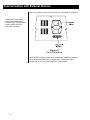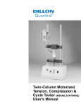
1
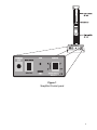
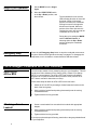
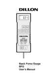
CAUTION
Risk of electrical shock. Do not remove cover. No user serviceable parts inside. Refer servicing to qualified service personnel.
Dillon reserves the right to change
specifications at any time.
02/10/99 SSUSER.P65 PN 29730-0014A Printed in USA
Table of Contents
Table of Contents ........................................................................... i
Specifications................................................................................. ii
Introduction .................................................................................... 1
Installing the SnapShot .................................................................. 1
Unpacking the SnapShot..................................................... 1
Operating the SnapShot ................................................................ 2
Start-up Procedure .............................................................. 2
Speed Setting ...................................................................... 2
Mode Setting ....................................................................... 2
Manual Operation ................................................................ 2
Single Cycle Operation ........................................................ 4
Emergency Stop .................................................................. 4
Force Gauges, Loadcellls and Your Fixturing ................................ 4
Attaching an AFG or BFG ................................................... 4
Attaching a Smart Loadcell ................................................. 4
Precautions .................................................................................... 5
Communication with External Devices........................................... 6
i
Specifications
Load capacity:
220lb (100kg, 1000N)
Power consumption:
150 watts (maximum)
Weight (stand only):
397lb (18kg)
CROSSHEAD MOTION
Travel range:
11.4in (290mm)
Maximum daylight:
17.3in (440mm)
Max headroom
(as in photograph):
13.0in (330mm)
Speed range:
0.5 - 19.7in/min (12.5 - 500mm/min)
Speed accuracy:
±10% of indicated speed
Speed indicated on stand:
Graduated dial
Direction of travel
indicated on stand:
By LED
Limit switch repeatability:
<0.02 in (0.5mm) (speed setting must be
unchanged)
Overrun at top speed:
<0.08in (2mm)
Operating modes:
Manual and single cycle with full speed
crosshead return
Reverse on alarm point:
Yes, with AFG/AFTI and cable (PN497561043)
Reverse on sample break:
Yes, with AFG/AFTI and cable (PN497561043)
SnapShot OPTIONS
Anvil plate:
6.3in (160mm) x 3.94in (100mm)
Female threads 10/32” UNF, 5/16” UNC
Force gauge & dovetail bracket
Smart loadcell, tension block module & AFTI
Simple logging/
plotting PC software:
ii
DataPlot
Introduction
The Dillon SnapShot Tension & Compression Tester is a single column
ballscrew-driven test frame with a load rating of up to 220 lb (1000N).
Complemented with a Dillon loadcell or force gauge, special fixtures and
accessories, it constitutes a key component in force measurement systems
suitable for accurately and reproducibly testing a wide range of products.
Read, understand and follow
all instructions in this manual
before operating the SnapShot.
There is only one standard model of the SnapShot. The dimensions, speed
range and capacity have been carefully optimized to cover the test procedures and specimen sizes most often needed by quality departments within
many sectors of manufacturing industry.
Thank you for choosing the Dillon SnapShot. With correct use it will give
many years of reliable service.
Installing the SnapShot
Unpacking the
SnapShot
If any damage is discovered do
not go any further with installation and do not connect the unit
to a power supply under any
circumstances.
The power supply for the test
frame must have a third-wire
earth ground. Connecting the
test frame to an outlet without
an earth ground is extremely
dangerous and could lead to a
risk of electrocution.
Upon receiving the unit please check for obvious physical damage to the
packaging material and the instrument itself. If any damage is evident, or if
any of the items listed below are missing, please notify your Dillon distributor
immediately.
• This User’s Manual
• Dovetail bracket (fitted to the crosshead)
• Appropriate power cable
• Allen key for crosshead dovetail and safety stop
• Four rubber feet with integral attachment screws, and hex key if
necessary
We strongly recommend you keep all packaging for future shipping requirements. Screw on (hand tighten only) the four rubber feet to the SnapShot.
Be sure you have adequate equipment available to safely lift the test frame
from the packaging. Trying to lift heavy items without adequate assistance
or the correct equipment may lead to accidental personal injury. Be careful
not to damage the limit switch thumbscrews behind the main vertical column.
Once removed from the packaging, place the test frame on a stable work
surface. Inspect the machine for any signs of obvious transit damage.
Check that the inlet voltage corresponds to your electrical installation —
either 220 VAC or 110 VAC. The machine has a label close to the power
connector which advises which voltage it is set for. If the machine does not
correspond to your supply, inform your local distributor.
After all the above points have been checked and confirmed to be correct
you may connect the machine to the power outlet only with the supplied
power cord. When power is applied the power indicator will illuminate. This
shows power is reaching the machine and is ready for use.
1
Operating the SNAPSHOT
Start-up Procedure
Pressing the red ‘Emergency
Stop’ button will, at any time,
stop the crosshead moving.
Note that the both up and down
LEDs will light.
Follow these steps to prepare your SnapShot for use:
1. Set the limit switches (see Figure 1) by turning each thumbscrew
located on the rear of the stand counterclockwise and moving them
approximately two inches either side of the moving crosshead and
retighten. See Figure 1.
2. Be sure your SnapShot is connected to an appropriate power supply.
3. Turn on the power switch shown in Figure 2. If the power bar does not
illuminate, turn the red emergency stop button in a clockwise direction.
Speed Setting
The SnapShot has variable test speed control. Return speed is constant at
the maximum speed. The white pointer on the speed control knobs gives an
indication of the speed setting. Some test standards place particular requirements upon speed accuracy/reproducibility, which may exceed the normal
performance of the SnapShot. Under such circumstances calibration of
each individual test stand may be appropriate.
Mode Setting
The mode switch allows you to choose Manual Control or Single Cycle
settings.
Manual Control - The crosshead will travel at the speed set by the speed
setting while the UP/DOWN switch is held in position.
Release the UP/DOWN switch to stop crosshead travel.
Single Cycle -
Manual Operation
The crosshead will move in the appropriate direction at
the preset speed when the UP/DOWN switch is tripped.
The crosshead will stop when the limit switch is tripped
and the crosshead will return at full speed.
Follow these steps to manually operate the SnapShot:
1. Set the MODE rocker switch to
Manual Control (up position).
2. Set the speed control knob to a
mid-range position (with pointer
close to 12 o’clock).
The crosshead will not move in
a given direction if it is against
a limit switch stop.
3. Hold the START/STOP toggle
switch in either the Up or Down
position…
4. Release the START/STOP switch
to stop the crosshead movement.
2
A red LED will illuminate showing
that the crosshead is moving and
indicating the direction of travel.
Figure 1
SnapShot Control panel
3
Single Cycle Operation
1. Set the MODE switch to Single
Cycle.
2. Move the START/STOP switch
to the Up or Down position, and
then release…
The crosshead will move and the
LED indicating direction of travel will
illuminate. When a limit switch
position is reached, the crosshead
will begin to travel in the opposite
direction at full speed. When the
position of the other limit switch is
reached, the motor will stop and the
crosshead will come to rest.
During the cycle, setting the MODE
switch to Manual Control, or
selecting either the Up or Down
position will stop the crosshead
movement.
Emergency Stop
Press the red Emergency Stop button to stop the crosshead movement at
any time. Both red LEDs light when the stop is engaged. To disengage the
stop button, turn it clockwise or counterclockwise and then release.
Force Gauges, Loadcells and Your Fixturing
Attaching an
AFG or BFG
You will need to attach a force measuring device to your SnapShot. This will
usually be a Dillon Advanced Force Gauge (AFG), a Basic Force Gauge
(BFG), or a smart loadcell. The AFG or AFTI can control the SnapShot
direction via an optional interface cable (PN 49756-1043). See the AFG/
AFTI User’s manual for instructions on setup.
Follow these steps to attach an AFG or BFG to the test frame:
1. Attach an AFG or BFG by screwing a dovetail extension bracket to the
back of the force gauge.
2. Slide it (with the loadcell stud pointing downwards) onto the moving
crosshead dovetail
3. Tighten with the hex key provided.
Attaching a Smart
Loadcell
1. Screw a smart loadcell into a tension block module with appropriate
adapter.
2. Slide it (with the loadcell stud pointing downwards) onto the moving
crosshead dovetail
3. Tighten with the hex key provided.
If you have purchased special fixturing, attach this to the gauge/loadcell and/
or your SnapShot.
4
Precautions
Loadcells and force gauges are delicate pieces of equipment and can easily
be damaged irreparably. One way of doing this would be to drive the crosshead downward until the loadcell (or loadcell stud on the force gauge) hits
something solid.
This is a risk when a user is not yet familiar with operating a new test stand.
Consequently the safety stop has been preset to significantly limit downward
travel of the crosshead. Adjust the limit switches according to your sample
dimensions and testing requirements.
• Make sure operators are
properly trained.
• Wear protective clothing
when destructive testing.
• Leave all machine guards
in place.
• Use safe work practices.
If the stand is equipped with the anvil plate accessory, be sure to align the
anvil fixture location in line with the force gauge you are using. Large and
small capacity gauges have different thread locations. The force must be
applied in line for tests to be accurate and to avoid gauge damage. Loosen
the screws holding the anvil and position the fixture before tightening the
screws.
Be sure to follow these important rules:
Operators should be fully trained on the safe use of this equipment.
The machine can generate forces which can cause serious injury.
Always disconnect the SnapShot from the power source when not in
use to avoid accidental starting of the machine.
Wear appropriate safety protection for your eyes at all times when
using the SnapShot. Extra body protection may be necessary if destructive testing is being done.
Install machine guarding if a risk assessment shows the need for such
measures.
If the machine fails to operate as expected, contact your Dillon supplier for support. Do not use the machine until it has been thoroughly
checked and returned to a safe working condition.
5
Communication with External Devices
There is an external control port at the rear of the SnapShot. See Figure 2.
The AFG/AFTI connector is
covered with a electrostatic
protective cap. This cap should
remain in place when the
connector is not used.
Figure 2
Control interfaces
The AFG/AFTI Interface, shown above, enables the SnapShot to respond,
via the appropriate Dillon cable, to signals from a Dillon AFG or AFTI.
Please refer to your AFG User’s Manual for further details.
6