1
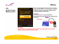
KWT-178AG Wireless Tester
User’s Guide v1.5
Preface
Copyright
There is no any clear or implicit assurance in the user's manual of our
company, including the assurance of selling or installing for the special
purpose. There are rival's volumes to carry on the power to alter or revise in
our company, if alter and forgive me for not issuing a separate notice. You
can’t duplicate any content of this manual by the written permission of our
company.
About the manual
The purpose to use this manual is for install the Wireless Tester. This
manual is including disposing course and method and helping the customer
to solve the unpredictable problem.
2
Index
1.
2.
3.
4.
5.
6.
7.
8.
9.
10.
11.
12.
13.
14.
15.
16.
17.
Product Overview ……………………………………………… 4
Hardware Specification ………………………………………. 5
Functions ……………………………………………………….. 8
External Buttons ………………………………………………. 9
Starting Page ……………………………………………………13
Main Functions ………………………………………………… 14
The Setup Page ………………………………………………... 16
Country Domain List ………………………………………….. 20
Channel Survey ………………………………………………... 26
BSS Survey ……………………………………………………. 30
Connecting Monitor …………………………………………. 36
Roaming Test …………………………………………………. 39
Auxiliary Tools ………………………………………………... 40
Example ………………………………………………………… 47
Trouble Shooting ……………………………………………… 52
Contact Information …………………………………………... 57
Limited Warranty ……………………………………………….58
3
1.
Product
Overview
KWT-178AG (the Tester) is a wireless testing device that operates in
Win CE platform. Supporting 802.11a/b/g/n protocol, it not only provides the
chosen wireless environment with complete information such as the signal quality
of each channel and the numbers of base stations, but also monitors all base
station of channels.
In addition, the Tester can help users to trace the information of selected base
stations, including the encryptions, the packets and the stations connecting to
base station.
The Tester also offers the engineers some practical tools for reference during site
survey or setting.
4
2.
Hardware
Specification
Intel PXA270 520MHz 32 bits RISC Processor
128 MB SDRAM and 128 MB Flash ROM
802.11 A/B/G, 5 dBi Dual Band Detachable Antenna x2
Antenna Connector, RP-SMA Jack
One USB port built in
240 x 320, 3.5” Color TFT Display
1 Numeric Keyboard with LED backlight
Wolfson WM9705 AC’ 97 codec with Touch screen controller
3000mAH, 7.4V Li-Ion battery pack
One rechargeable backup battery
Dimension 192.5mm (L) x 91.3mm / 78mm (W) x 42.2mm / 60.6mm (H)
Weight:560g with Standard Battery Pack
OS. WinCE. NET5.0 Professional
Environmental
Operation: -10~50℃ ; Storage: -20~79℃
Humidity: Operation- 10%~80%
IP54Certificated, IP64 compliant
1.2m (4ft) drop to concrete certificated
1.5m (5ft) drop to concrete, System no broken
5
2a.
Package
Content
Styli
Tester
Dual Band
Antenna x2
Li-ion
Battery
Carrying bag with strap
DC
Adapter
Power
Cord
U Disk
USB Host Cable
6
2b.
Accessories
Model
Connector 1
Connector 2
Description
WC-D0N0-5CT
RP-SMA Plug
N Plug
For Outdoor Antenna
WC-D0D1-5CT
RP-SMA Plug
RP-SMA Jack
For Indoor Antenna
WC-D0C1-5CT
RP-SMA Plug
RP-TNC Jack
For Cisco Antenna
WC-D0S1-5CT
RP-SMA Plug
SMA Jack
For Attenuator (Tester Side)
WC-D0S0-5CT
RP-SMA Plug
SMA Plug
For Attenuator (Normal AP Side))
WC-C0S0-5CT
RP-TNC Plug
SMA Plug
For Attenuator (Cisco AP Side)
WC-N0S0-5CT
N Plug
SMA Plug
For Attenuator (Outdoor AP Side)
Attenuator-S0S1-10
SMA Plug
SMA Jack
Attenuator 10dB
Attenuator-S0S1-20
SMA Plug
SMA Jack
Attenuator 20dB
Attenuator-S0S1-30
SMA Plug
SMA Jack
Attenuator 30dB
7
3.
Functions
Sensitivity
Up to -100 dbm
Instant Power On
Yes
Operation
Easy
Equipment Design
Industrial PDA
Continuous Operation
4 Hrs
Defense
IP64 Water-Proof / Dust-Proof
Passable with dropping to Concrete Ground from 1.5Meters
Package
Dual-Purpose Holster ; Usage for Shoulder and Waist
Data Output
USB / USB host Cable
Signal Strength Test
Yes, All Channels
Usage of Channel
(Quantity of Base Station in each Channel)
Yes
Score of Channels
Yes
Scanning Base Station
A/B/G/N in the same time
Information of Base Station
SSID/BSSID/RSSI, Sorting, Channel Selection
Base Station Tracing
Yes
Information of Specified Base Station
Yes
Roaming-Test Report
Yes
Security’s Detecting
Yes
Clients’ Status of Specified Base Station
Yes
Status of Base Station
Data Rate (54/48/../6/11/../1 Mbps ; Frame (Ctl/Mgt/Data/Error/retry)
Rogue AP Detecting
Yes
Rogue Client Detecting
Yes
Linking Test
Offer the ratio of transition and Revelation of Signal’s Strength
Aux. Tools
Free Space Attenuation ; Power Meter
Effective Range Calculation ; Output Power Translator (mW/ dBm)
Base Station Detector ; Network User Detector
8
4.
External
Buttons
Antenna B for 2.4GHz
Antenna A for 5GHz
Power Button
Scan Button
Scan Button
Power Socket
USB Host
9
Insert the Styli into
The holder
4a.
Touch Pen
Styli
The Styli
Pen Holder
There are 2
Positions for
selection
10
4b.
USB Interface
Antenna B for 2.4GHz
B
Power Socket
Antenna A for 5GHz
A
USB Host
USB Host Cable
USB socket
11
4c.
LED Signal
Battery Status LED
Battery Low
Other hot keys
F1 + F4, Reset System
F1 + F4 + Power, Reset to Factory Default
F2 Back Light Setting,
Push the button to keep the backlight
shining. Press one more time to go back
to original setting.
Battery Charging Status LED
Red: Charging
Green: Charging Completely
12
5.
Starting
Page
The function table will be right on after starting the system.
13
6.
Main
Function
The Tester is designed to offer various
kind of reliable functions to detect,
analyze and observe the assigned
wireless environments for the purpose
of trouble shootings.
With the collected information we can
optimize the best infrastructure or
setup certain Precautions to the
negative impacts that will cause To the
network.
There are 5 main functions for users to quick switching the option:
Basic Setting: Set up the region (Country/Area), time and check the status of Battery
Channel Survey: Information of each channel
BSS Survey: Information of the base station on each channel
Roaming Test: Check if the construction of base station is suitable for roaming
Aux. Tools: Including the Attenuation of Free Space ; Measurement of Power ;
Calculation of Effective Range ; Conversion of power unit (mW/ dBm)
Detection of Base Station ; Detection of Wireless Client
14
6a.
Instant
Function Keys
These keys help users switch to various pages.
Setup
Save
Export
Home
Soft
Keyboard
Setup: <click the button> The Tester will be switched to basic setting page
Save: <click the button> The page and the collected data can be stored
Export: <click the button> The saved files can be exported to external USB disk
Home: <click the button> Switch to main page
Soft Keyboard: <click the button> the keyboard will be showed on the screen
15
7.
The Setup
Page
The setup contains the region (WLAN) settings
and the system settings
1. Region settings:
Choose the proper area. While changing the
settings, please push both “F1” and “F4”
buttons at the same time to save and start the
new setting.
2. System settings:
The page displays battery status, the
configuration of time, date as well as volume,
and tools for firmware upgrading.
And firmware upgrade tools (picture showed as
below)
<NOTICE>
The storage will be filed as the name of date. Please adjust the right time
and date before using the Tester at first.
16
7.
The Setup
Page
Status of battery
Setup for data and time
Control of volume
and sound
17
7a.
Firmware
Update
Steps in upgrading firmware:
1. Connect U disk which contains the file,
wirelesstester.bin, to Tester with USB host cable.
2. Click “Update” button in Basic Setting page, displayed
as the left picture.
3. Click “Update” button
4. After the updating is completed, a new page will show
up as below.
5. Click F1+F4+Power to restart Tester for completing
upgrade.
Copy wirelesstester.bin
to the root directory of U disk
18
7a.
Firmware
Update
6. A caution as left picture will appear on the screen if U
disk is not properly connected or the file wirelesstester.bin
cannot be found, please renew the upgrading.
19
Region
8.
Country
Domain
List (1)
2.4G(B/G)
5G (A)
Albania
1-13
Algeria
1-13
Argentina
1-13
56,60,64,149,153,157,161
Armenia
1-13
36,40,44,48,52,56,60,64
Australia
1-13
36,40,42,44,48,50,52,56,58,60,64,149,152,153,157,160,161,165
Austria
1-13
36,40,44,48
AZERBAIJAN
1-13
36,40,44,48,52,56,60,64
BAHRAIN
1-13
36,40,44,48,52,56,60,64,149,153,157,161,165
BALARUS
1-13
BELGIUM
1-13
36,40,44,48,52,56,60,64,100,104,108,112,116,120,124,128,132,136,140
BELIZE
1-13
149,152,153,157,160,161,165
BOLIVIA
1-13
149,152,153,157,160,161,165
BRAZIL
1-13
36,40,44,48,52,56,60,64,100,104,108,112,116,120,124,128,132,136,140,149,153,157,161,165
BRUNEI
DARUSSALAM
1-13
149,152,153,157,160,161,165
BULGARIA
1-13
36,40,44,48,52,56,100,104,108,112,116,120,124,128,132,136,140
CANADA
1-11
36,40,42,44,48,50,52,56,58,60,64,149,152,153,157,160,161,165
CHILE
1-13
36,40,42,44,48,50,52,56,58,60,64,149,152,153,157,160,161,165
CHINA
1-13
149,152,153,157,160,161,165
COLOMBIA
1-11
36,40,44,48,52,56,60,64,149,153,157,161,165
COSTA_RICA
1-13
20
Region
8.
Country
Domain
List (2)
2.4G(B/G)
5G (A)
CROATIA
1-13
36,40,44,48,52,56,60,64
CYPRUS
1-13
36,40,44,48,52,56,60,64
CZECH
1-13
36,40,44,48,52,56,60,64
DENMARK
1-13
36,40,44,48,52,56,60,64,100,104,108,112,116,120,124,128,132,136,140
DOMINICAN
REPUBLIC
1-11
36,40,42,44,48,50,52,56,58,60,64,149,152,153,157,160,161,165
ECUADOR
1-13
EGYPT
1-13
EL_SALVADOR
1-13
ESTONIA
1-13
36,40,44,48,52,56,60,64,100,104,108,112,116,120,124,128,132,136,140
FAEROE_ISLANDS
1-13
36,40,44,48,52,56,60,64,100,104,108,112,116,120,124,128,132,136,140
FINLAND
1-13
36,40,44,48,52,56,60,64,100,104,108,112,116,120,124,128,132,136,140
FRANCE
1-13
36,40,44,48,52,56,60,64
FRANCE2
1-13
36,40,44,48,52,56,60,64
GEORGIA
1-13
36,40,44,48,52,56,60,64
GERMANY
1-13
36,40,44,48,52,56,60,64,100,104,108,112,116,120,124,128,132,136,140
GREECE
1-13
36,40,44,48,52,56,60,64,100,104,108,112,116,120,124,128,132,136,140
GUATEMALA
1-11
36,40,42,44,48,50,52,56,58,60,64,149,152,153,157,160,161,165
HONDURAS
1-13
HONG_KONG
1-13
36,40,42,44,48,50,52,56,58,60,64,149,152,153,157,160,161,165
HUNGARY
1-13
36,40,44,48,52,56,60,64
36,40,44,48,52,56,60,64
21
Region
8.
Country
Domain
List (3)
2.4G(B/G)
5G (A)
ICELAND
1-13
36,40,44,48,52,56,60,64,100,104,108,112,116,120,124,128,132,136,140
INDIA
1-13
36,40,44,48,52,56,60,64,149,153,157,161,165
INDONESIA
1-13
149,153,157,161,165
IRAN
1-13
149,152,153,157,160,161,165
IRAQ
1-13
149,152,153,157,160,161,165
IRELAND
1-13
36,40,44,48,52,56,60,64,100,104,108,112,116,120,124,128,132,136,140
ISRAEL
1-13
ITALY
1-13
36,40,44,48,52,56,60,64,100,104,108,112,116,120,124,128,132,136,140
JAMAICA
1-13
36,40,44,48,52,56,60,64,100,104,108,112,116,120,124,128,132,136,140
JAPAN
1-14
34,38,42,46
JAPAN1
1-14
34,38,42,46
JAPAN2
1-11
34,38,42,46
JAPAN3
1-14
8,12,16,34,38,42,46,184,188,192,196
JAPAN4
1-14
34,38,42,46
JAPAN5
1-14
34,38,42,46
JAPAN6
1-13
34,38,42,46
JORDAN
1-13
36,40,44,48,149,153,157,161,165
KAZAKHSTAN
1-13
KENYA
1-13
KOREA_NORTH
1-13
149,152,153,157,160,161
22
Region
8.
Country
Domain
List (4)
2.4G(B/G)
5G (A)
KOREA_ROC
1-13
36,40,44,48,52,56,60,64,100,104,108,112,116,120,145,149,153,157,161,165
KOREA_ROC2
1-13
149,153,157,161
KUWAIT
1-13
LATVIA
1-13
LEBANON
1-13
LIBYA
1-13
LIECHTENSTEIN
1-13
36,40,44,48,52,56,60,64,100,104,108,112,116,120,124,128,132,136,140
LITHUANIA
1-13
36,40,44,48,52,56,60,64,100,104,108,112,116,120,124,128,132,136,140
LUXEMBOURG
1-13
36,40,44,48,52,56,60,64,100,104,108,112,116,120,124,128,132,136,140
MACAU
1-13
36,40,42,44,48,50,52,56,58,60,64,149,152,153,157,160,161,165
MACEDONIA
1-13
MALAYSIA
1-13
56,60,64,149,153,157,161
MALTA
1-13
36,40,44,48,52,56,60,64,100,104,108,112,116,120,124,128,132,136,140
MAXICO
1-11
36,40,42,44,48,50,52,56,58,60,64,149,152,153,157,160,161,165
MONACO
1-13
36,40,44,48,52,56,60,64
MOROCCO
1-13
NETHERLANDS
1-13
36,40,44,48,52,56,60,64,100,104,108,112,116,120,124,128,132,136,140
NEW_ZEALAND
1-13
36,40,44,48,52,56,60,64,149,153,157,161,165
NICARAGUA
1-13
36,40,44,48,52,56,60,64,149,153,157,161,165
NORWAY
1-13
36,40,44,48,52,56,60,64,100,104,108,112,116,120,124,128,132,136,140
36,40,44,48,52,56,60,64,100,104,108,112,116,120,124,128,132,136,140
23
Region
8.
Country
Domain
List (5)
2.4G(B/G)
5G (A)
OMAN
1-13
36,40,44,48,52,56,60,64,149,153,157,161,165
PAKISTAN
1-13
PANAMA
1-11
36,40,42,44,48,50,52,56,58,60,64,149,152,153,157,160,161,165
PARAGUAY
1-11
36,40,42,44,48,50,52,56,58,60,64,149,152,153,157,160,161,165
PERU
1-13
149,153,157,161,165
PHILIPPINES
1-13
149,152,153,157,160,161,165
POLAND
1-13
36,40,44,48,52,56,60,64,100,104,108,112,116,120,124,128,132,136,140
PORTUGAL
1-13
36,40,44,48,52,56,60,64,100,104,108,112,116,120,124,128,132,136,140
PUERTO_RICO
1-11
36,40,42,44,48,50,52,56,58,60,64,149,152,153,157,160,161,165
QATAR
1-13
ROMANIA
1-13
RUSSIA
1-13
SAUDI_ARABIA
1-13
SINGAPORE
1-13
36,40,42,44,48,50,52,56,58,60,64,149,152,153,157,160,161,165
SLOVAKIA
1-13
36,40,44,48,52,56,60,64,100,104,108,112,116,120,124,128,132,136,140
SLOVENIA
1-13
36,40,44,48,52,56,60,64,100,104,108,112,116,120,124,128,132,136,140
SOUTH_AFRICA
1-13
36,40,44,48,52,56,60,64,100,104,108,112,116,120,124,128,132,136,140,149,153,157,161,165
SPAIN
1-13
36,40,44,48,52,56,60,64,100,104,108,112,116,120,124,128,132,136,140
SWEDEN
1-13
36,40,44,48,52,56,60,64,100,104,108,112,116,120,124,128,132,136,140
SWITZERLAND
1-13
36,40,44,48,52,56,60,64,100,104,108,112,116,120,124,128,132,136,140
24
Region
8.
Country
Domain
List (6)
2.4G(B/G)
5G (A)
SYRIA
1-13
Taiwan
1-11
THAILAND
1-13
TRINIDAD_Y_TOBAG
O
1-13
36,40,44,48,52,56,60,64
TUNISIA
1-13
36,40,44,48,52,56,60,64
TURKEY
1-13
36,40,44,48,52,56,60,64
UAE
1-13
UKRAINE
1-13
UNITED_KINGDOM
1-13
36,40,44,48,52,56,60,64,100,104,108,112,116,120,124,128,132,136,140
UNITED_STATES
1-11
36,40,42,44,48,50,52,56,58,60,64,149,152,153,157,160,161,165
UNITED_STATES_FC
C49
1-11
36,40,42,44,48,50,52,56,58,60,64,149,152,153,157,160,161,165,188,189,190,192,193,194,196,197
URUGUAY
1-13
149,153,157,161
UZBEKISTAN
1-11
36,40,42,44,48,50,52,56,58,60,64,100,104,108,112,116,120,124,128,132,136,140,149,152,153,157,160,16
1,165
VENEZUELA
1-13
149,153,157,161
VIET_NAM
1-13
YEMEN
1-13
ZIMBABWE
1-13
56,58,60,64,149,152,153,157,160,161
25
9.
Channel
Survey
Select 802.11b/g or 802.11a from the bar.
(Default value is b/g)
Signal Level show the signal strength
on each channel
AP Amount Calculate the total quantities of
the detected base station.
For example: number 4 on channel 1 stands
for that there are 4 base stations on channel
1
Score According to the signal strength,
Tester will score the channels to 3 levels:
Blue one means excellent
Green means middle and
Red means poor
Users may select different Radio Mode in detecting, like the current frequency is
802.11b/g showed above, it might be switched to be 802.11a. The default value is
B/G pattern.
Select the wanted channel, system will lead you to enter the function of selected
channel
26
The saved information
Net Mode
9.
Channel
Survey
B/G
Signal Level
Channel No.
Signal Level
AP Amount
Score
1
-68
4
40
2
-74
1
52
3
-100
0
81
4
-100
0
100
5
-100
0
92
6
-90
3
74
7
-100
0
92
8
-100
0
100
9
-100
0
100
10
-100
0
92
11
-88
4
65
File name: all_bg_channel_survey_time_03_52_12.csv
Click the ‘Save’ button, the following information will be stored:
a. Channel Survey Page
b. All scoring information in each channel
27
This page shows the detailed information of the selected channel:
9a.
The Selected
Channel
a. The red curve on the top of the graph indicates a real-time status of the
wireless signal. The range of sensitivity is from -100 dBm to -10 dBm as
detecting.
b. The table in the middle lists the detailed information for of the base stations
in the detected channel, such as SSID, BSSID, Security and RSSI.
c. Click one of the base stations, the system will lead you to the function of
BSS Survey.
28
The saved information
9a.
The Selected
Channel
Current Channel Signal
Net Mode
Channel Number
b/g
Signal (dBm)
6
-87
Current Channel BSS List
SSID
BSSID
Security
RSSI
Seednet WT II
00:19:CB:51:94:04
Wep
-90
D-link G700AP
00:19:5B:09:C2:64
WPA-PSK-TKIP
-91
victor
00:15:E9:0E:08:7C
Wep
-89
WANG
00:18:F3:7A:9E:E5
WPA-PSK-TKIP
-87
File name: bg_channel_6_time_04_14_19.csv
Click the ‘Save’ button, the following information will be stored:
a. The selected channel page
b. All information of base stations in the present channel, including SSID, BSSID,
Security and RSSI.
29
10.
BSS Survey
All channels
Selected channel
a. This function is to detect the distributing status of base station in each channel.
All base stations are listed on the table to reveal their signal strength and other
related information.
b. User may filter out unnecessary channels to make the detecting more clear.
Only informations of wanted channels are listed on the table, including SSID,
BSSID, Security and RSSI.
30
10.
BSS Survey
c. The Tester is designed to detect any ‘unfriendly’ base station
That is operating in the existed wireless environments.
As it is necessary to recognize whether the disallowed base stations exist in the
surrounding, users may click “ImportMAC” button to check the file APLIST.txt,
that is exported from U disk. Allowed base stations will be showed in yellow, and
disallowed ones will be in red. If APLIST.txt is unseen, all defaults will be revealed
in yellow.
31
The saved information
BSS List
10.
BSS Survey
Channel
SSID
BSSID
Security
RSSI
1
jobehsieh
00:18:84:29:20:0A
WPA-PSK-TKIP
-90
1
asus
00:17:31:26:99:E4
Wep
-65
1
FON_jobehsieh
00:18:84:29:20:09
Open-None
-89
1
NCTU
00:16:01:7F:BC:D1
Open-None
-91
1
eric630218
00:1B:11:26:A8:D6
Wep
-92
11
WLBARGLV2-00-0A-79-B8-8D-35
00:0A:79:B8:8D:35
Open-None
-88
11
default
00:50:FC:F4:7A:56
Wep
-94
11
Hau
00:16:01:98:0F:6B
Wep
-92
11
default
00:0E:2E:F6:63:D9
Wep
-87
Click the ‘Save’ button, the following information will be stored:
a. BSS Survey Page
b. Information of all base stations in the surroundings,
including channel, SSID, BSSID, Security and RSSI.
32
10a.
Exporting
Data
Connect U disk to Tester
The saved files can be exported to the portable USB disk:
a. Connect U disk to the Tester with the USB Host Cable
b. Click ‘Export’ button to export datas from Tester to U Disk
c. If U Disk is not connected to the Tester, a caution will appear on the page,
please plug U Disk in again.
33
10b.
Observation
of The
Selected
Base Station
Base station information
Client list
Base station status
a. This function displays the real status of the selected base stations for detecting
and tracing, such as the continuous performance of signal strength.
b. The page displays 3 main detail information, including the data as well as status
of base station and something about the client connecting to this base station.
If necessary, click “Connect” button, the Tester will connect the base station in
client mode for further detecting.
34
10b.
Observation
of The
Selected
Base Station
Information of the base station:
Wireless Mode
Authorization Method
Identification Code of Wireless Network
Channel
Encryption Method
Base Station ID
Supportive Bandwidth
Information of Clients:
The list to connected clients, including the MAC address, RSSI, Packet information.
Status of Base Station:
Supporting Standard (11A / 11B / 11G / 11N)
Status of packet, including control, management, data and warning included retry times.
Network is supported to be something wrong which having a serious rety.
About:
About showing IP address.
35
11.
Connection
Monitor
Wireless Data Rate
Base Station’s RSSI
Ping Test
Bandwidth
The function is designed to proceed online test, it not only reveals data rate
and signal intensity but also responds the ping reaction of the Tester to base
station so that efficiency of base station can be figured out.
Column Bandwidth reveals the transporting bandwidth between Tester and
the base station that is expected to be tested.
36
11a.
Connection
Configuration
Before connecting to the base station expected to be tested,
users have to previously complete the setup of basic
parameters, including the relevant parameters of base station,
the certification method, the tested IP address and the
Tester’s IP address.
Certification method: Open / Share / WPA / WPA2 /
WPA-PSK /WPA-PSK2
Encryption method: Open >> None / WEP
Share >> None / WEP
WPA
>> AES / TKIP
WPA2 >> AES / TKIP
WPA-PSK >> AES / TKIP
WPA2-PSK >> AES / TKIP
Golden Key Index: Key 1 ~ Key 4
Golden Key Input:
Certification Method:
Enable 802.1x
EAP Type (None / TLS / TTLS / PEAP)
37
11a.
Connection
Configuration
Certification List
Login Name
Password
Relevant setup of Ping
Local IP address
Destination IP address
IP Reference Setting
Use DHCP (Dynamic Host Configuration Protocol)
Use Current IP Address (Use fixed IP address for setting)
Contains IP Network Address, Subnet Mask, Default Gateway
After the connecting is completed, the Tester will display real Data Rate and
Strength. As settings are correct, the Tester will immediately show the
responses that Tester pings on base stations and the real throughput.
38
12.
Roaming
Test
The steps of roaming test:
a. Select the preferred SSID
(Attention: All APs are requested to have the same SSID.)
b. When a SSID is selected, there goes a page that represents the signal
strength and channel of the base stations receiving the same SSID
according to the current location.
c. Based on the mobile location, users observe the signal strength of base
station to judge whether the connection will be interrupted as removing,
or not.
Poor
Poor for
Roaming
Good Good for
Roaming
39
13.
Auxiliary
Tool
This function contains 6 auxiliary tools:
1.
2.
3.
4.
5.
6.
Free Space Loss
Power Meter
Distance Calculation
AP Detector
Client Finder
mW / dBm Conversions
40
13a.
Free Space
Loss
This table offers the calculation of decline in power
under different frequency and range
41
13b.
Output Power
Measurement
The tool is designed to measure the real output
power of base station, to our suggest, connect a
20 dB attenuator at least before measuring to
avoid the damage to the Tester.
Reminder:
A 20dB attenuator is recommended to
be connected and used before the measurement
is started.
Attenuator
AP
Warning:
It will cause the damage to the Tester if an attenuator is not used
before measuring the output power.
42
13c.
Distance
Calculation
Assign different modulation, data rate, output power and antenna gain to
calculate the maximum range (effective distance) between the 2 base stations.
43
13d.
AP Detector
This function assists users to quickly find the base station.
Entering this page, the Tester will list out all base stations, users need to select
the preferred one and click “Searching” button to detect.
The closer the Tester approaches to the preferred base station, the hurrier the
sound from the Tester will be.
Please click “STOP” button to suspend the detecting if need.
44
13e.
Client Finder
This function makes users search the target client quickly. User have to key in
the MAC address of the target client and then click “ Searching” button, the
Tester will find this target client and reveal the results on the page below,
including the status, the MAC address of base station, the signal strength, the
radio mode, the modulation and total packets.
Please click “STOP” button to suspend the detecting if need.
45
13f.
mW / dBm
Converstion
This function provides an instant conversion of mW into dBm
or dBm into mW.
46
14.
Sample
Applications
[Quality Analysis of Wireless Environment]
47
14.
Sample
Applications
[Detecting of the Base Station in the environment]
48
14.
Sample
Applications
[Detecting of the illegal base station]
49
14.
Sample
Applications
[Test of Bridging]
Bridge + Antenna
WiScan + Antenna
50
14.
Sample
Applications
[Test of Antenna Efficiency]
Fixed distance
Alteration to the
antennas.
51
a. Notice before starting the Tester
15.
Trouble
Shooting
@ Charge the battery at least 6 hours before using the Tester which contains 2
rechargeable Li-ION batteries. One of them is the main battery that supplies
electric power to whole system, another is the backup battery that provides
necessary electric power for maintaining the data in Flash ROM. Both the
batteries will charge at the same time while the system is charging.
When the charging light turn green, it means the batteries are finished
charging.
b. How to handle the situation of no display as booting and a red light shows up
above of screen?
@ This might be the problem of starting electric power. Please push F1+F4+Power
button to restart the system several times until the Tester is booted correctly.
52
c. How to deal with the problem of LED light above screen turns red?
15.
Trouble
Shooting
@ This indicates the electric capacity of main battery is in a weak position. Please
charge or replace the battery as soon as possible to keep the work normally
executed.
d. How to solve the problem that a blue page shows up while the testing page
suddenly disappears as using?
@ This is caused by wrong execution of programs. Please push F1+F4 button to
restart the Tester, or execute the step of power off / power on.
e. No messages can be found when scanning the base stations :
@ This often occurs due to a repeated scanning within a short period. It takes 10
seconds for the Tester to make a complete scan, but a hurried scan could
probably enforce the Tester to continue the next scan without ending
previous one, then a programming error might happen. Please restart the
Tester by the step of power off / power on.
53
15.
Trouble
Shooting
f. Upgrading is unavailable
@ Possibilities
1. The firmware has not been copied to the root directory of U disk.
2. Use other USB Flash Disk instead of the U disk attached by the Tester.
3. USB Host cable is broken or connected incorrectly.
4. An error happens to the file name. The correct file name should be
Wirelesstester.bin
g. The files done with the Tester cannot be exported to the U Disk
(Some possibilities):
@ 1. The Disk included in the package should be used in the first place
instead of other USB flash disk.
2. The USB host cable may be broken or has not been installed properly.
3. The U Disk memory is full, in order to preserve more space, some of
the files in the disk should be cleaned and removed, after that please try to
export the files again.
54
15.
Trouble
Shooting
f. Upgrading is unavailable
@ Possibilities
1. The firmware has not been copied to the root directory of U disk.
2. Use other USB Flash Disk instead of the U disk attached by the Tester.
3. USB Host cable is broken or connected incorrectly.
4. An error happens to the file name. The correct file name should be
Wirelesstester.bin
g. Data can not be exported
@ Possibilities
1. Use other USB Flash Disk instead of the U Disk attached by the Tester.
2. USB Host Cable is broken or unconnected correctly.
3. The memory of the U Disk is full, some of files should be cleaned out,
then export the data again
55
15.
Trouble
Shooting
h. How to clear up the problem of firmware’s upgrading incomplete?
@ This is resulted from the insufficient power. Please charge the battery with AC
adapter and restart the Tester again, if it still cannot be booted, push F1+F4 to
restart once more. If it doesn’t work still, please contact the dealer to send the
Tester back to the manufactory.
NOTICE:
To our strong suggestion, please charge the Tester with AC adapter all the time
during the upgrading procedure.
56
16.
Contact
Information
Need to contact Formosa?
Visit us online for information on the latest products and updates to your existing
products at:
http://www.tw-wireless.com
Can't find information about a product you want to buy on the web? Do you want
to know more about networking with Formosa products? Give our advice line a
call or fax your request in to:
Tel: +886-3-5616277
Fax:+886-3-5616275
Don't wish to call? You can e-mail us at:
[email protected]
If any Formosa product proves defective during its warranty period,
you can call the Formosa Return Merchandise Authorization
department for obtaining a Return Authorization Number at:
Tel: +886-3-5616277
Fax:+886-3-5616275
FAE Support
[email protected]
57
17.
Limited
Warranty
This Warranty constitutes the sole and exclusive remedy of any buyer or reseller’s equipment and the sole and
exclusive liability of the supplier in connection with the products and is in lieu of all other warranties, express,
implied or statutory, including, but not limited to, any implied warranty of merchantability of fitness for a particular
use and all other obligations or liabilities of the supplier.
In no even will the supplier or any other party or person be liable to your or anyone else for any damages,
including lost profits, lost savings or other incidental or consequential damages, or inability to use the software
provided on the software media even if the supplier or the other party person has been advised of the possibility
of such damages.
The following are special terms applicable to your hardware warranty as well as services you may use during part
of the warranty period. Your formal Warranty Statement, including the warranty applicable to our Wireless LAN
products, appears in the Quick Installation Guide which accompanies your products.
Duration of Hardware Warranty: One Year
Replacement, Repair or Refund Procedure for Hardware:
If there is an unexpected power failure or operate unsuitable artificially when firmware upgrade. Please contact
with local commercial agent.
If your unit needs a repair or replacement, return it to your dealer/distributor in its original packaging. When
returning a defective product for Warranty, always include the following documents:
1. The Warranty Repair Card
2. A copy of the invoice and proof of purchase.
3. The RMA Report Form (To receive a Return Materials Authorization form (RMA), please
contact the party from whom you purchased the product).
Upon proof-of-purchase we shall, at its option, repair or replace the defective item at no cost to the buyer.
This warranty is contingent upon proper use in the application for which the products are intended and does not
cover products which have been modified without the reseller’s approval or which have been subjected to
unusual physical or electrical demands or damaged in any way.
58