1
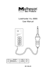
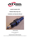
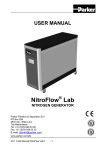
USER’S MANUAL N2-MISTRAL-0 / 25 L/min NITROGEN GENERATOR Rev. 3 - August 2008 MATHESON TRI-GAS 166 Keystone Drive Montgomeryville, PA 18936 Phone: 215-641-2700 Fax: 215-641-2714 Email: [email protected] User’s Manual N2-MISTRAL-0-25L Page 2 / 21 Content 1 2 3 INTRODUCTION 4 1.1 1.2 1.3 1.4 1.5 1.6 1.7 4 4 5 5 5 5 5 HEALTH, SAFETY AND ENVIRONMENTAL ASPECTS 6 2.1 2.2 2.3 2.4 2.5 6 6 6 7 7 5 6 8 General ........................................................................................................................... 8 Separation principle ........................................................................................................ 8 Process parameter ......................................................................................................... 8 Process scheme ............................................................................................................. 9 System components ...................................................................................................... 10 TECHNICAL SPECIFICATIONS 11 4.1 4.2 11 12 General ......................................................................................................................... Performance Table & Air consumption ......................................................................... INSTALLATION 13 5.1 5.2 5.3 5.4 5.5 13 13 13 13 13 Transport ...................................................................................................................... Location ........................................................................................................................ Unpack and check equipment ...................................................................................... Connection to compressed air feed and nitrogen consumer ........................................ Commissioning of a N2-MISTRAL-0-25L ...................................................................... OPERATION 6.1 6.2 6.3 6.4 6.5 7 General ........................................................................................................................... Compressed air .............................................................................................................. Nitrogen and oxygen ...................................................................................................... Safety precautions .......................................................................................................... Environmental aspects ................................................................................................... DESCRIPTION OF THE APPLIANCE 3.1 3.2 3.3 3.4 3.5 4 General ........................................................................................................................... Pictograms in this manual .............................................................................................. Identification and service ................................................................................................ Certificates ...................................................................................................................... Correct use ..................................................................................................................... User instructions ............................................................................................................. Liability ............................................................................................................................ 15 Start-up of N2-MISTRAL-0-25L ..................................................................................... 15 Modes of Operation ............................................................................................................. 15 Stop Operation ............................................................................................................. 16 Trouble shooting ........................................................................................................... 17 Adjustments on PSH .................................................................................................... 18 MAINTENANCE 19 7.1 7.2 7.3 7.4 19 20 21 21 Maintenance scheme ................................................................................................... Replace filter element in AFM40-F02D & AFD40-F02D ............................................... Automatic drain in AFM40-F02D & AFD40-F02D .......................................................... Replace filter & O-rings in AMF250-F02 ......................................................................... User’s Manual N2-MISTRAL-0-25L Page 3 / 21 1. Introduction 1.1 General This manual forms an integral part of the product. The manual describes the installation, daily operation, maintenance and troubleshooting. Content Please read the manual carefully before you start with the operation of the N2-MISTRAL-0. Condition of change Changes to the N2-MISTRAL-0 can only be made after explicit written permission by Matheson TriGas. Non-conformance to this rule, as well as any consequential damage, loss or any costs are the responsibility of the owner & user. Information All information in this manual, including additional drawings and technical descriptions, remains the property of the Matheson Tri-Gas and may not be used (otherwise than for the use of this product), copied, multiplied or published to or for a third party without explicit written permission by Matheson Tri-Gas. 1.2 Pictograms in this manual In this manual the following pictograms are used: Warning A warning shows a hazard that can cause death or serious injury. Follow the instructions. Caution A caution shows a danger that can cause damage to the equipment. Follow the instructions. Warning Risk for death due to suffocation Risk of fire Oxygen-enriched air leads to an increased risk of fire in the event of contact with inflammable products. High-pressure risk Follow the instructions with respect to compressed gasses. Environment Instructions with respect to the environment User’s Manual N2-MISTRAL-0-25L Page 4 / 21 1.3 Identification and Service The identification plate is located on the side of the N2-MISTRAL-0 and shows the characteristics of the generator. For service and technical assistance, please contact your distributor. 1.4 Certificates The N2-MISTRAL-0 meets the following requirements: Subject Applicable standard EC Pressure equipment directive (PED) Sound engineering practice Quality assurance ISO 9001:2000 Environmental care ISO 14001:1996 1.5 Correct use The N2-MISTRAL-0 is intended to make nitrogen out of normal (clean) compressed ambient air. The system is based on gas separating membranes. If the generator is installed in a laboratory with air, polluted by VOCS, solvents or exhaust from GC instruments or any other contaminant, the inlet filters may not be able to remove all of these contaminants and may require replacement more often than recommended later in this manual. In the worst case, the membranes can be damaged. Consequently, Matheson Tri-Gas will not accept any liability for improper use. The N2-MISTRAL-0 is in compliance with the prevailing directives and standards. Only use this N2MISTRAL-0 in a technically perfect condition, in conformity with the purpose as described above. 1.6 User instructions Only a well-trained user(s) is allowed to work on the N2-MISTRAL-0. The user(s) must be aware of hazards related to operating the N2-MISTRAL-0 and processes connected to it. All personnel working on the N2-MISTRAL-0 must have free access to the manuals. 1.7 Liability Matheson Tri-Gas will not accept any liability if: The instructions in this manual are ignored. Replacement parts are used which are not approved by Matheson Tri-Gas. The N2-MISTRAL-0 is operated incorrectly. The system is fed with other gasses than compressed air. The N2-MISTRAL-0 is modified without notification and authorization of Matheson Tri-Gas. Maintenance and repair are not carried out by qualified service engineers and according to the instructions. User’s Manual N2-MISTRAL-0-25L Page 5 / 21 2 Health, safety and environmental aspects 2.1 General Correct use of the N2-MISTRAL-0 nitrogen generator is important for your personal safety and for trouble-free operation. Incorrect use can cause damage to the N2-MISTRAL-0 or lead to incorrect gas supply. Warning 2.2 Please read this manual before you start the installation and putting the generator into operation. Prevent accidents and damage to the N2-MISTRAL-0. Contact your supplier if you detect a problem that you cannot solve with this manual. Use the N2-MISTRAL-0 in accordance with its purpose. Refer to chapter 1.5. Only service-engineers, qualified to work on electric and pneumatic equipment, and properly trained on this equipment, are allowed to do the installation, maintenance and repairs. Do not tamper or experiment with the equipment. Do not exceed the technical specifications for the N2-MISTRAL-0. Refer to chapter 4. Compressed air Warning 2.3 Make sure that the inlet air pressure cannot exceed 12 bar(g) at any time. Make sure that the equipment and the pipes are connected correctly and specified to withstand the applied input air pressure. Depressurise the N2-MISTRAL-0 and the connected systems before you disconnect parts and system. The sudden escape of compressed air can cause serious injury or damage. Do not tamper or experiment with the equipment. Do not exceed the technical specifications for the N2-MISTRAL-0. Nitrogen and oxygen The N2-MISTRAL-0 generates nitrogen as a product. Oxygen enriched air is released as waste. Warning 2.4 Nitrogen can cause suffocation! Oxygen-enriched air leads to increased risk of fire in the event of contact with inflammable products. Make sure that there is adequate ventilation at all times! The N2-MISTRAL-0 can be used for installation in an Exx-classified area. (no electric parts – all pneumatic) Safety precautions Warning Make sure that the ventilation rate is sufficient in the room where the enriched oxygen is ventilated, or lead the enriched air outside. Keep the ambient temperature between 10 and 40 °C (50 to 104 ° F). User’s Manual N2-MISTRAL-0-25L Page 6 / 21 2.5 Install the peripheral equipment, piping and nitrogen storage vessels according to standard procedures. The Matheson Tri-Gas cannot take responsibility for this. Do regular maintenance to the N2-MISTRAL-0, to ensure proper and safe operation. Refer to chapter 7. Make sure that instructions concerning health and safety are compliant with the local legislation and regulations. Environmental aspects The use and maintenance of the N2-MISTRAL-0 does not represent environmental dangers. Most parts are made of metal and can be disposed in the regular way. The packaging of the N2-MISTRAL-0 is 100% recyclable. Make sure that instructions concerning health, safety and environment are compliant with the local legislation and regulations. User’s Manual N2-MISTRAL-0-25L Page 7 / 21 3 Description of the appliance 3.1 General The N2-MISTRAL-0 separates compressed air into nitrogen and an oxygen enriched air stream. The separation system is based on hollow fibre membranes. The produced Nitrogen can be connected directly to the application or can be stored in a Nitrogen storage vessel. In the latter case, the N2-MISTRAL-0 switches on and off at specific pressure levels which can be adjusted, and this with a frequency depending on the nitrogen demand. 3.2 Separation principle Fig.1 A B C Pressurized air inlet Hollow fibre membrane Nitrogen outlet F S Fast permeation Slow permeation Clean ambient air contains nitrogen (78.2%), oxygen (20.8%), Argon (1%), carbon dioxide, water vapour and traces of other inert gases. Pressurized air (A) is led through hollow fibre membranes (B). The various air components diffuse through the porous wall of the membranes. The diffusion rate differs for the various gases: Oxygen and water vapour have a high diffusion rate and diffuse rapidly through the membrane wall. Nitrogen has a low diffusion rate and diffuses slowly through the membrane wall. Pressurized nitrogen is released at the outlet of the membranes (C) which can be stored in a nitrogen storage vessel or directly used in e.g an LCMS. 3.3 Process parameters The nitrogen production depends on following parameters: Flow rate The lower the flow rate of nitrogen, the more oxygen can diffuse through the membrane wall. As a result, the nitrogen produced at the outlet, will be more pure. Adjust the purity of the nitrogen with the flow control valve. Please consult the tables II-III later in this manual for more details on purity, nitrogen production and required air consumption at different feed pressures. User’s Manual N2-MISTRAL-0-25L Page 8 / 21 Temperature The N2-MISTRAL-0 operates optimally at a temperature of about 20-25 °C. If the temperature increases, the pressurised air consumption will also increase. Therefore, do not place the system in a room where the temperature may rise unnecessarily high. Membrane pressure A higher membrane pressure will increase the capacity of the N2-MISTRAL-0. Permeate outlet There must be atmospheric pressure at the permeate outlet. The capacity and the selectivity of the system decrease strongly if the external pressure exceeds the atmospheric pressure. 3.4 Process scheme Fig.2 0.3 μm and 0.01 μm particle size Coalescing filters Carbon filter AMF250-F02 Pneumatically controlled valve Gas separating membranes (only M1 is available in Model-0-25 L/min) FCV Flow control valve V1 Non-return-valve PCV1 pressure regulator PI1, PI2 Pressure gauges PSH Pneumatical pressure switch, controls valve Y1 (* =AFM40-F02D and ** = AFD40-F02D) Air from the external compressor / supply travels through the filters F-01 & F-02 & F-03 and enters the membranes when the pneumatic valve Y1 is closed. This depends on the output pressure Pl2 (gauge visible on the front panel) and is controlled by means of the pressure switch PSH. When the generator leaves the factory, the PSH is set such that valve Y1 opens when the output pressures reaches 7 bar and closes again when the output pressure drops below 6 bar (hysteresis of ca. 1 bar- can be adjusted). The (back) pressure regulator PCV1 is fully open (fully CW). Output flow is adjusted with the needle valve FCV and affects the nitrogen purity. FCV is factory set for 98 % purity at nominal conditions of the corresponding model. The pressure gauge Pl1 is not visible when the front panel is installed. The pressure drops to zero when valve Y1 opens. For more details on operation, please see sections 6.2 & 6.5. The non-return valve V1 is necessary to avoid that the stored nitrogen from a connected buffer tank would be released back into the generator after valve Y1 opens the circuit. F-01*, F-02** F-03 Y1 M1, M2 User’s Manual N2-MISTRAL-0-25L Page 9 / 21 3.5 System components Air control Valve Y1 PSH Pressure gauge Pl2 FCV Pressure regulator PCV1 Filter F-03 Pressure gauge Pl1 Filters F-01 & F-02 Fig.3 User’s Manual N2-MISTRAL-0-25L Page 10 / 21 4 Technical specifications 4.1 General Delivery pressure N2-MISTRAL-0-25L Maximum delivery (output) pressure Inlet pressure minus 1 bar Compressed air Maximum feed pressure bar(g) 12 bar(g) (175 psig) Minimum feed pressure bar(g) 4 bar(g)….(58 psi) Compressed air temperature 10 to 40 º C (50 to 104 º F) Required air purity ISO 8573.1 Class 1.2.1 Dirt, Water,Oil Pressure dew point ≤ 5 º C (41º F) N2 Humidity Dew point suppression: -50 º C (-58º F) Air treatment section 1 µ and 0.1 µ coalescing filter + carbon filter Ambient conditions Temperature 10 to 40°C (50 to 104°F) Noise level Less than 45 dB(A) Dimensions and connections Dimensions (H x W x D) 810 x 290 x 190 mm Net weight 22 kg Connection inlet G¼" Connection outlet G¼" Output 3 Capacity at nominal conditions * 1.5 Nm /hr (25 litres/min) Purity at specified capacity (% by volume) ≥ 98 % N2 * Nominal conditions: feed pressure at inlet 8 bar(g), ambient temperature 20°C, ambient pressure 1013 mbar Parts Standard 1 x N2-MISTRAL-0 unit 1 x Manual Optional Active carbon adsorber for air pre-treatment Table I User’s Manual N2-MISTRAL-0-25L Page 11 / 21 4.2 Performance Table Minimum Production Capacity in Nm3 / hr* Nitrogen Purity % 99 98 97 96 95 BY feed Pressure: 4 bar (g) 0.39 0.65 0.88 1.11 1.40 5 bar (g) 0.48 0.81 1.10 1.39 1.74 6 bar (g) 0.61 1.05 1.42 1.80 2.19 7 bar (g) 0.72 1.22 1.66 2.10 2.56 8 bar (g) 0.82 1.49 1.90 2.40 2.92 9 bar (g) 0.93 1.61 2.19 2.77 3.39 10 bar (g) 1.02 1.74 2.37 3.00 3.65 11 bar (g) 1.12 1.91 2.62 3.33 4.07 12 bar (g) 1.22 2.09 2.87 3.66 4.48 Table II N2 Mistral -0-Standard Factory set. Max. Nitrogen capacity = min. capacity + 30% * at nominal conditions Air consumption Air consumption in Nm3/hr at min. capacity* Nitrogen Purity % 99 98 97 96 95 By feed pressure of :4 bar (g) 2.47 2.80 3.09 3.34 3.63 5 bar (g) 3.08 3.50 3.86 4.17 4.53 6 bar (g) 3.81 4.39 4.83 5.21 5.70 7 bar (g) 4.44 5.12 5.64 6.08 6.65 8 bar (g) 5.08 5.96 6.44 6.95 7.60 9 bar (g) 5.86 6.74 7.46 8.04 8.82 10 bar (g) 6.45 7.32 8.06 8.69 9.50 11 bar (g) 7.41 8.42 9.16 9.98 10.60 12 bar (g) 8.05 9.18 10.00 11.00 11.70 Table III Changes of the relevant parameters will affect the purity of the Nitrogen. Any changes have to be done by qualified service personal from Matheson Tri-Gas or trained personal from our official representatives. Otherwise Matheson Tri-Gas cannot take any responsibility for possible poor performance of the Mistral-0. User’s Manual N2-MISTRAL-0-25L Page 12 / 21 5. Installation 5.1 Transport Warning! 5.2 1. Put the N2-MISTRAL-0 in the original box during transport over longer distances. For qualifications of personnel, refer to chapter 2.1. Location Install the N2-MISTRAL-0 in a location, meeting following requirements: Indoors, fixed to a wall Dry Vibration free No continuous direct radiation by sunlight Away from heat sources Properly ventilated room, refer chapter 2.3 and 2.4 Easy accessibly for operation and service Perform the complete installation procedure again if the N2-MISTRAL-0 is moved to a new location. 5.3 1. 2. 3. 5.4 Unpack and check equipment Open the packaging. Make sure that all components are delivered. Make sure that the supplied compressed air is correct: If the N2-MISTRAL-0 is connected to a house air system, make sure that the compressed air pressure and quality fulfil requirements and that the flow capacity is sufficient. If the N2-MISTRAL-0 is connected to a stand-alone compressor, make sure that the compressor works properly. Refer to the instructions of the compressor supplier. Make sure that the cooler and the water separator of the compressor work correctly. Make sure that the oil 3 content of the compressed air is below 0.01 mg/m . Make sure that the pressurised air dryer is of proper size and that it works fine. Connection to compressed air feed and nitrogen consumer Warning 1. 2. 5.5 1. 2. Make sure that the inlet and outlet tubes are free of dust, particles, metal parts and curls, liquids and grease before you connect the N2-MISTRAL-0. Connect the generator outlet to the application or the storage vessel. For tyre inflation, mostly a special filling gun is used. Connect the compressed air supply to the generator air inlet. Commissioning of a N2-MISTRAL-0 Make sure that the connections are correct and fixed well. Make sure that the compressed air pressure is as high as required.(default 8 bar) User’s Manual N2-MISTRAL-0-25L Page 13 / 21 3. 4 5. Make sure that the instrument has no leaks, which may have arisen due to transport. Remove the front panel and monitor the pressure gauges. Cap off the generator outlet, open the compressed air supply and monitor both pressure gauges. When the output pressure reaches 7 bar (default), the PSH opens valve Y1 and pressure on Pl1 drops to zero. Pressure Pl2 slowly goes down (due to a small consumption in the PSH) and by ca. 6 bar, valve Y1 should close again until the output pressure reaches 7 bar, valve Y1 opens etc….For other pressure settings or modes of Operation, please see section 6.2 -Modes of Operation. 6. Shut off compressed air, re-install the front panel and connect the application or buffer tank 7. The system is ready for use now. Note: When NO buffer tank is used between Mistral-0 and consumer application, the ON/OFF modus should not be used. Indeed, depending on the flow and feed capacity, the frequency (and resulting noise) of the valve Y1 switching may be so high that the user may believe some components are broken, which is actually not the case. However, the fast ON/OFF switching will likely lead to premature failure of some components and should be avoided. User’s Manual N2-MISTRAL-0-25L Page 14 / 21 6 Operation 6.1 1. 2. 3. Start-up of N2- MISTRAL-0 Open the compressed air supply. The system is ready for use now. The system will start to produce nitrogen as soon as the nitrogen outlet is opened. The specified purity will be available according to the air inlet pressure and flow adjustment. Important Note: When the feed pressure is too low (< 0.5 bar), the inlet filters will remain open and air leaves through the automatic drain port! Water vapour from the compressor air will condensate in the filter housing and automatically be released through the drain port. 6.2 Modes of Operation The generator can work in continuous mode or in ON-OFF mode A. Continuous mode. This mode is used when the generator supplies N2 directly to an application. Assume following starting conditions / requirements: 1) Feed pressure of compressed air is 9 bar 2) PSH upper pressure is set for 7 bar (default)-hysteresis 1 bar. 3) the required output pressure is 5 bar. Procedure: Shut off the air supply and remove the front panel in order to have access to the pressure regulator and gauge Pl2. a) Connect a needle valve or flow controller in series with a flow meter (rotameter) to the output of the generator. Open this needle valve / flow controller (NOT the FCV in Fig.2) such that a small flow can be expected. b) Apply the air supply. Since the PSH is set to switch off at 7 bar (default), it will open valve Y1 as soon as the 7 bar is reached and pressure will decrease, valve Y1 closes again etc… c) loosen the lock screw on the pressure regulator and adjust output pressure by turning the knob counter-clockwise to get 5 bar output pressure. As soon as the pressure drops below the 6 bar, the PSH switch will keep valve Y1 closed. Tighten the lock screw. Note: when the PSH switches back and forward between upper and lower setting, short burst of nitrogen will be released through the top of the switch (see Fig.4). This is NORMAL! d) adjust the needle valve to get a flow close to the specified capacity and see if the output pressure remains stable. e) Shut off the air supply and connect the application. Verify correct operation. Assume following starting conditions / requirements: 1) Feed pressure of compressed air is 10 bar 2) PSH upper pressure is set for 7 bar (default)-hysteresis 1 bar. 3) the required output pressure is 8 bar Procedure: a) Connect a needle valve / flow controller in series with a flow meter (rotameter) to the output of the generator. Open the needle valve / flow controller for a small flow. b) Apply the air supply. Since the PSH is set to switch off at 7 bar (default), it will open valve Y1 as soon as the 7 bar is reached and pressure will decrease, valve Y1 closes again etc.. c) Loosen the lock-nut A on the PSH switch (Fig. 4) while holding position of set-screw C with another wrench. Adjust screw B (looking from the top, turning Clockwise increases the switch off pressure setting) such that valve Y1 remains closed. Tighten lock-nut A. User’s Manual N2-MISTRAL-0-25L Page 15 / 21 d) Now adjust the pressure regulator for 8 bar output. Increase flow with the needle valve until specified capacity is reached and see if pressure remains stable. e) shut off air supply ,connect the application and check for proper operation. B. ON-OFF mode. This mode is used in combination with a buffer tank. Assume following starting conditions/requirements: 1) feed pressure of compressed air is 10 bar 2) PSH upper pressure is set for 7 bar (default)-hysteresis 1 bar. 3) the required output pressure (switch OFF) is 8 bar and Switch ON = 7 bar. Shut off the air supply and remove the front panel in order to have access to the pressure regulator and pressure gauges. a) Connect a needle valve / flow controller in series with a flow meter (rotameter) to the output of the generator. Open the needle valve / flow controller for some flow. b) Apply the air supply. Since the PSH is set to switch off at 7 bar (default), it will open valve Y1 as soon as the 7 bar is reached at Pl1. Pressure will decrease, valve Y1 closes again etc… Monitor the output pressure at Pl2. With the pressure regulator PCV1 fully CW (default), pressure Pl1 and Pl2 are similar during the time the valve Y1 is closed. c) Loosen the lock nut A on the PSH switch (Fig.4) while holding nut C with another wrench. Adjust screw B (turning Clockwise increases the switch-OFF pressure setting) such that valve Y1 opens at 8 bar. Tighten lock nut A. d) verify that valve Y1 closes again at ca. 7 bar (Pl2) otherwise repeat the procedure. e) shut off air supply and connect the buffer tank. The tank volume should be big enough to avoid too frequent valve switching. f) Apply air supply and verify for correct operation. 6.3 Stop operation of N2-MISTRAL-0 1. Shut off the compressed air supply before you perform maintenance. 2. Depressurise the system by venting the nitrogen outlet. 3. Make sure that the system is fully depressurised by checking the pressure gauge. TIP: Should the coalescing filters not be fully depressurized, it is possible to de-pressurize these manually by turning the black knob CCW on the drain outlet. Than close again. User’s Manual N2-MISTRAL-0-25L Page 16 / 21 6.4 Trouble shooting Error Delivery of nitrogen too low or absent N2MISTRAL-0 does not automatically switch off Possible cause Possible solution Compressed air supply too low Check/increase the air supply Ambient temperature is too high Lower the temperature, if possible Compressed air temperature is too high Lower the temperature, if possible Air filters are polluted Change or clean the air filters Leak in piping Check for leaks in the piping. Automatic drain is continuously open Check the automatic drain (chapter 7) Nitrogen outlet line is blocked Check/open the outlet line Defective valve Y1 or switch PSH Replace & call service Blockage Check the compressed air supply Feed pressure too low Increase feed pressure Ambient temperature is too high Lower the temperature if possible Compressed air temperature is too high Lower the temperature if possible Air filters are polluted Change or clean the air filters Leak in piping Check for leaks in the piping Nitrogen outlet is open Close outlet Defective valve Y1 or switch PSH Replace & call service Table IV User’s Manual N2-MISTRAL-0-25L Page 17 / 21 6.5 Adjustments on the PSH. Reference is made to Fig.4. The switch-off pressure is adjusted with top screw B. Before an adjustment can be done, it is necessary to loosen lock-nut A while holding nut C with another wrench to avoid changing the hysteris setting. Turning screw B clockwise will increase the set point. When the pressure drops below value = upper set point – hysteresis (default 1 bar), the switch will close valve Y1. Note: This hysteresis can be changed with set - screw C after lock-nut D is released. It is strongly recommended NOT to change this setting as there is NO need for it. Misadjustment can lead to fast ONOFF switching and damage. If settings have been changed and the PSH seems to react improperly, the default settings (7 bar upper - 6 bar lower set point) can be +/- restored by positions of the set-screws as shown in for Fig.4B. Set-screw B Lock-nut A Set-screw C Lock-nut D Fig.4 Distance to top of set-screw B 63.6 mm Fig.4B User’s Manual N2-MISTRAL-0-25L Distance to top of set -screw C 48 mm Page 18 / 21 7 Maintenance 7.1 Maintenance scheme Part Action Frequency Filter Kit P/N MM025-FILT-KIT Replace filter elements Refer to chapter 7.2 & 7.4 Annual or earlier when the pressure loss in each filter becomes ≥ 1 bar. Contains filtering media: p/n MFTR-0299-XX (AFM40P) p/n MFTR-0300-XX (AFD40P) p/n MFTR-0301-XX (AMF-EL250) Filter Kit p/n MM025-FILT-KIT Filtering media P/N MFTR-0299-XX Filtering media P/N MFTR-0300-XX Filtering media P/N MFTR-0301-XX Fig. 5 User’s Manual N2-MISTRAL-0-25L Page 19 / 21 7.2 Replace filter elements in AFM40-F02D & AFD40-F02D 1. 2. 3. 4. 5. 6. 7 8. Close the air supply with input valve. Let the system depressurize until the pressure gauge PI1 in Fig. 2, reads 0 bar. if necessary turn knob (A) CCW (Fig.6) to make sure the filter is depressurized. Than close again. Turn the filter housing (C) counter clockwise -while pushing knob (B) down- until the markings I & II line up, than pull the filter housing (C) from the filter head (E). Unscrew the old filter element (F) - Fig.7 Clean the sieve and the filter housing, if necessary. Place a new filter element (F). Assemble the parts in the opposite direction. Input Open &Close valve Filter head (E) black knob (B) Filter housing (C) Turn knob (A) CCW (open) to depressurize and close again. Fig.6 Automatic drain port with Quick fitting to connect a drain tube. User’s Manual N2-MISTRAL-0-25L Page 20 / 21 Filtering media (F) Fig.7 7.3 Automatic drain When the automatic drain valve remains open when the black knob (A) is in the “Closed (S)” position (fully CW), replacement of the whole filter is recommended. 7.4 Replace filter & O-rings in AMF250-F02 To open the filter housing, remove the 4 screws from the top and replace the elements show in Fig.5 (P/N MFTR-0301-XX). Remove 4 screws from the top to open the housing . Fig.8 User’s Manual N2-MISTRAL-0-25L Page 21 / 21