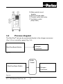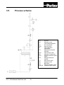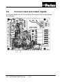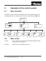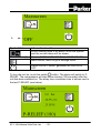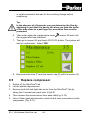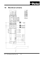
1
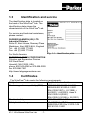
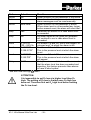
USER MANUAL
®
NitroFlow Lab
NITROGEN GENERATOR
Parker Filtration & Separation B.V.
PO Box 258
4870 AG - Etten-Leur
The Netherlands
Tel: +31 (0)76-508 53 00
Fax: +31 (0)76-508 53 33
E-mail: [email protected]
www.parker.com/pfs
K3.1.142e Manual NitroFlow Lab.1
-1-
© 2009 Parker Filtration & Separation B.V.
All rights reserved
No part of this publication may be reproduced and/or publicized by being printed, photocopied,
placed on microfilm or in any other manner without the prior written permission of Parker
Filtration & Separation B.V.
Parker Filtration & Separation B.V. retains the right to make changes in parts at any point
without first or directly notifying the customer. The contents of this manual can also be
changed without prior warning.
This manual is valid for the NitroFlow® Lab in its standard version. Parker Filtration &
Separation B.V. can therefore not be held liable for specifications of the delivered system that
may deviate from the standard version.
For information concerning adjustments, maintenance or repairs not contained in this manual,
please contact Parker Filtration & Separation B.V.
This manual has been prepared with all possible care, but Parker Filtration & Separation B.V.
cannot accept responsibility for possible errors in this document or for the consequences
thereof.
K3.1.142e Manual NitroFlow Lab
-2-
USER MANUAL ...........................................................................................1
1
INTRODUCTION ...................................................................................5
1.1
1.2
1.3
1.4
1.5
1.6
1.7
2
HEALTH, SAFETY AND ENVIRONMENTAL ASPECTS.....................9
2.1
2.2
2.3
2.4
2.5
3
General.........................................................................................16
Capacity data................................................................................19
Maintenance kit ............................................................................19
INSTALLATION ..................................................................................20
5.1
5.2
5.3
5.4
5.5
5.6
6
General.........................................................................................12
Separation principle......................................................................12
Parts .............................................................................................13
Process diagram...........................................................................14
Process scheme ...........................................................................15
TECHNICAL SPECIFICATIONS.........................................................16
4.1
4.2
4.3
5
General...........................................................................................9
Nitrogen and oxygen ......................................................................9
Electricity ......................................................................................10
Safety precautions........................................................................10
Environmental aspects .................................................................11
DESCRIPTION OF THE APPLIANCE ................................................12
3.1
3.2
3.3
3.4
3.5
4
General...........................................................................................5
Pictograms......................................................................................6
Identification and service................................................................7
Certificates......................................................................................7
Use in accordance with purpose ....................................................8
User instructions.............................................................................8
Liability............................................................................................8
Transport ......................................................................................20
Define location..............................................................................20
Unpack and check equipment ......................................................21
Connect nitrogen consumer .........................................................21
Connecting power.........................................................................21
Connect input and output signals .................................................22
OPERATION OF THE CONTROL SYSTEM ......................................24
6.1
Menu structure..............................................................................24
K3.1.142e Manual NitroFlow Lab
-3-
6.2
Main screen ..................................................................................24
6.3
Settings menu
.........................................................................26
6.3.1
Log on menu
....................................................................27
6.3.2
Alarm settings menu
........................................................28
6.3.3
Pressure switch menu
....................................................30
6.3.4
Options menu
..................................................................31
6.3.5
Local settings menu
.........................................................32
6.3.6
Maintenance menu
..........................................................33
6.3.7
Data logging menu
..........................................................36
7
OPERATION .......................................................................................38
7.1
7.2
7.3
7.4
7.5
8
®
Commisioning NitroFlow Lab......................................................38
®
Start NitroFlow Lab .....................................................................39
Adjusting the purity .......................................................................39
Control of the outlet pressure .......................................................40
®
Stop NitroFlow Lab .....................................................................41
TROUBLESHOOTING ........................................................................42
8.1
Error list ........................................................................................42
8.2
Alarm messages
9
...............................................................43
MAINTENANCE ..................................................................................45
9.1
9.2
9.3
9.4
9.5
9.6
Maintenance scheme ...................................................................45
Replace inlet filter element ...........................................................45
Replace oxygen sensor................................................................47
Calibrate oxygen sensor...............................................................47
Replace compressor.....................................................................48
Software updates..........................................................................50
10
ELECTRICAL SCHEME ..................................................................52
11
INDEX ..............................................................................................53
K3.1.142e Manual NitroFlow Lab
-4-
1
Introduction
1.1
General
®
The NitroFlow Lab is a product of Parker Filtration & Separation B.V. This
manual forms an integral part of the product. The manual describes the
installation, daily operation, maintenance and troubleshooting.
Content
®
Read the manual carefully before you start with the NitroFlow Lab. These
instructions must be thoroughly understood before installing and operating
this product. Failure to operate this product in accordance with the
instructions set forth in this manual and by other safety governing bodies
will void the safety certification of this product. If you have any questions or
concerns, please call your local representative or the technical services
department:
Europe +(44) 1622 7233 00, USA +(1) 800 343 4048
Condition of change
®
No changes may be made to the NitroFlow Lab as supplied, without
explicit prior written permission by Parker Filtration & Separation B.V. Nonconformance to this rule, as well as any consequential damage, loss and
costs are the responsibility of the owner and the user.
Information
All information in this manual, including additional drawings and technical
descriptions, remains the property of Parker Filtration & Separation B.V.
and may not be used (otherwise than for the use of this product), copied,
multiplied or published to or for a third party without explicit prior written
permission by Parker Filtration & Separation B.V.
K3.1.142e Manual NitroFlow Lab
-5-
1.2
Pictograms
In this manual and on the generator, the following pictograms are used:
Warning
A warning shows a hazard that can cause death or
serious injury. Follow the instructions.
Caution
A caution shows a danger that can cause damage to the
equipment. Follow the instructions.
Electricity
High voltage: danger of electric shock.
Warning
Risk for death due to suffocation.
Risk of fire
Oxygen-enriched air leads to an increased risk of fire in
the event of contact with inflammable products.
High-pressure risk
Follow the instructions with respect to compressed
gasses.
Environment
Instructions with respect to the environment.
Read instructions in the manual.
K3.1.142e Manual NitroFlow Lab
-6-
1.3
Identification and service
The identification plate is located on
®
the back of the NitroFlow Lab. The
identification plate shows the
®
characteristics of the NitroFlow Lab.
For service and technical assistance,
please contact:
PARKER HANNIFIN (UK) LTD
Industrial Division
Suite 42, Kent House, Romney Place
Maidstone, Kent ME15 6LH, England
Tel: +44 (0)1622 772440
Fax: +44 (0)1622 772446
For North America:
PARKER HANNIFIN CORPORATION
Filtration and Separation Division
242 Neck Road
Haverhill, MA 01835, USA
phone: 800-343-4048 or 978-858-0505
fax: 978-556-7501
http://www.labgasgenerators.com
1.4
Fig. 1-1: Identification plate
Certificates
®
The NitroFlow Lab meets the following requirements:
Subject
Applicable standard
Electromagnetic compatibility (EMC)
NEN-EN-IEC 61000-6-3:2001
NEN-EN-IEC 61000-6-1:2001
EN 61326(1997) + A1(1998) +
A2(2001) + A3(2003), class A
EN 61000-3-2(2000)
EN 61000-3-3(1995) + A1(2001)
Electrical safety
NEN EN 60204-1:2001
st
Safety for laboratory use
UL 61010A-1 (1 Ed)
CAN/CSA-C22.2 No. 61010-1-04
IEC 61010-1:2001
K3.1.142e Manual NitroFlow Lab
-7-
Safety of pressure equipment
Installation
Quality assurance
Environmental care
1.5
Sound engineering practice
IEC 61010-1 Cat II
ISO 9001:2000
ISO 14001:2004
Use in accordance with purpose
®
The NitroFlow Lab is intended to produce nitrogen out of normal ambient
air. The system is based on gas separation membranes. Each different or
further use will not be in conformity with the purpose. Parker Filtration &
Separation B.V. will not accept any liability for improper use.
®
The NitroFlow Lab is in compliance with the prevailing directives and
®
standards. Only use this NitroFlow Lab in a technically perfect condition, in
conformity with the purpose as described above.
1.6
User instructions
®
Only well-trained personnel are allowed to work on the NitroFlow Lab. The
®
user must be aware of hazards related to operating the NitroFlow Lab and
®
processes connected to the NitroFlow Lab. The user is responsible for the
®
safety of the personnel. All personnel working on the NitroFlow Lab must
have free access to the applicable manuals.
1.7
Liability
Parker Filtration & Separation B.V. will not accept any liability if:
•
The instructions in this manual are ignored.
•
Replacement parts are used which are not approved by the
manufacturer.
•
The NitroFlow Lab is operated incorrectly.
•
The system is fed with other gasses than air.
•
The NitroFlow Lab is modified without notification and authorization of
Parker.
•
Maintenance and repair are not carried out according to the
instructions.
®
®
K3.1.142e Manual NitroFlow Lab
-8-
2
Health, safety and environmental
aspects
2.1
General
®
Correct use of the NitroFlow Lab nitrogen generator is important for your
®
personal safety and for trouble-free functioning of the NitroFlow Lab.
®
Incorrect use can cause damage to the NitroFlow Lab or can lead to
incorrect gas supply.
Warning
• Read this manual before you start the installation and
®
putting into operation of the NitroFlow Lab. Prevent
®
accidents and damage to the NitroFlow Lab.
• Contact your supplier if you detect a problem that you
cannot solve with this manual.
®
• Use the NitroFlow Lab in accordance with its
purpose. Refer to §1.5.
• Only service-engineers, qualified to work on electric
and pneumatic equipment, are allowed to do the
installation, maintenance and repairs. Unqualified
people are not allowed to repair the equipment. Refer
®
to §1.6. Lift the NitroFlow Lab with a forklift. Follow
the legislation and instructions for operating the
forklift.
• Do not tamper or experiment with the equipment. Do
not exceed the technical specifications for the
®
NitroFlow Lab. Refer to chapter 4.
2.2
Nitrogen and oxygen
®
The NitroFlow Lab generates nitrogen as a product. Oxygen enriched air
is released as waste.
Warning
• Nitrogen can cause suffocation!
•
Oxygen-enriched air leads to increased risk of fire in
the event of contact with flammable products. Make
sure that there is adequate ventilation at all times!
K3.1.142e Manual NitroFlow Lab
-9-
•
•
2.3
®
The NitroFlow Lab is not designed for installation in
an Exx-classified area.
®
Do not install the NitroFlow Lab in an area where
explosive mixtures may occur.
Electricity
Warning
• Only service-engineers, qualified to work on electrical
equipment, are allowed to do the installation,
maintenance and repairs.
• Disconnect the main power supply before you do the
maintenance or repair.
®
• If a service-engineer has to work on the NitroFlow
Lab while the electric power it is connected, the
service-engineer must be very careful with respect to
the electric hazards.
2.4
Safety precautions
Warning
• Make sure that the ventilation rate is sufficient in the
room where the enriched oxygen is ventilated, or lead
the enriched air outside. Keep the ambient
temperature between 10 and 35 °C.
• Install the peripheral equipment, piping and nitrogen
storage vessels according to standard procedures.
Parker Filtration & Separation B.V. cannot take
responsibility for this.
®
• Do regular maintenance to the NitroFlow Lab, to
ensure proper and safe operation. Refer to chapter 8.
• Make sure that instructions concerning health and
safety are compliant with the local legislation and
regulations.
K3.1.142e Manual NitroFlow Lab
- 10 -
2.5
Environmental aspects
®
The use and maintenance of the NitroFlow Lab does not include
environmental dangers. Most parts are made of metal and can be disposed
®
in the regular way. The packaging of the NitroFlow Lab is 100%
recyclable. Optimal sizing of buffer tanks and setting of the pressure switch
will result in minimal energy consumption. The lower the delivery pressure,
the longer the lifetime of the system.
According to EC-regulations electrical systems have to be disassembled
and recycled at the end of their life. Parker Filtration & Separation B.V. can
support you in this.
Make sure that instructions concerning health, safety and
environment are compliant with the local legislation and
regulations.
K3.1.142e Manual NitroFlow Lab
- 11 -
3
Description of the appliance
3.1
General
®
The NitroFlow Lab separates compressed air produced by an on-board
compressor into nitrogen and an oxygen enriched air stream. The
separation system is based on membranes.
3.2
Separation principle
B
A
C
H2O - H2
F
O2
N2
S
Fig. 3-1: Separation principle
A
B
C
Pressurized air inlet
Hollow fibre membrane
Nitrogen outlet
F
S
Fast permeation
Slow permeation
Ambient air contains nitrogen (78.1%), oxygen (20.9%), argon (1%), carbon
dioxide, water vapor and traces of other inert gasses. Pressurized air (A) is
led through hollow fibre membranes(B). The various air components diffuse
through the porous wall of the membranes.
The diffusion rate differs for the various gasses:
•
Oxygen and water vapor have a high diffusion rate and diffuse rapidly
through the membrane wall.
•
Nitrogen has a low diffusion rate and diffuses slowly through the
membrane wall.
Pressurized nitrogen enriched air is released at the outlet of the
membranes (E) which can be stored in a nitrogen storage vessel.
K3.1.142e Manual NitroFlow Lab
- 12 -
3.3
Parts
A Nitrogen compressor
B Hollow fiber membrane
and heat exchanger (M)
C Air compressor
D Inlet carbon adsorber (C)
E Purity adjustment valve(FCV)
F Oxygen sensor
G Sample flow control valve (do not
adjust) (FCV)
H Touch screen display
I Pressure control valve (PCV)
J SD-card
K Pressure relief valve (PSV)
L Non-return valve (V1)
K3.1.142e Manual NitroFlow Lab
- 13 -
M Main switch/ circuit
breaker
N Electrical feed cable
O Product outlet /ball valve
P Ventilation outlet
(keep clear)
3.4
Process diagram
®
The NitroFlow Lab can be connected directly to the nitrogen consumer
(Fig. 3-3) or to a buffer vessel (Fig. 3-4).
Nitrogen
Consumer
NitroFlow Basic Mobile
Fig. 3-3
Buffer
Vessel
NitroFlow Basic Mobile
Nitrogen
Consumer
Fig: 3-4
K3.1.142e Manual NitroFlow Lab
- 14 -
3.5
Process scheme
N1
N2
C
LP
RKV
M
PI1
FCV
HP
PCV
PI2
V1
N2
V2
V4
PSV1/2
K3.1.142e Manual NitroFlow Lab
- 15 -
Air inlet
Nitrogen outlet
Inlet carbon adsorber
Air compressor
Start up valve
Gas separation
membrane
Membrane pressure
indicator
Flow control valve
Nitrogen compressor
Nitrogen pressure relief
valve
Nitrogen pressure
indictor
Non return valve
Nitrogen outlet
Ball valve
Depressurisation valve
Pressure relief valves
4
Technical specifications
4.1
General
Delivery pressure
Maximum delivery pressure
8 bar(g)/116 psig
Ambient conditions
Temperature
10 to 35 °C / 50 to 95 °F
Air quality
Normal clean ambient air, relative
humidity < 90%
Max. ambient relative humidity
<80 % to 31°C, 50% at 40°C
Noise level
< 65 dB(A) @ 1 meter/3 ft
Heat dissipation
1000 W (@50 Hz), 1200 W (@60
Hz) 3850 (50Hz)/4625 (60 Hz)
BTU/hr
Dimensions and connections
Dimensions (H x W x D) [mm]
700 x 900 x 310
Dimensions (H x W x D) [inch]
27.6 x 35.4 x 12.2
Net weight
92.5 kg / 204 lbs
Connections
outlet: G ¼ “ / ¼” NPT
Electrical data
1
Voltage/frequency
120Vac/60Hz, 230Vac/50Hz
Power consumption
1400 W
Plug/receptacle
230V/50Hz can be mounted locally
as to local requirements
115V/60Hz: 20A/125 VAC; NEMA 520 straight blade
1
Mains supply voltage fluctuations not to exceed +/- 10% of nominal voltage.
K3.1.142e Manual NitroFlow Lab
- 16 -
Default software settings
Menu
What
Default setting
Logs
Delay-time
180 sec
Local settings
Language
English
Local settings
Pressure
Bar
Local settings
Flow
LPM
Local settings
Purity
%O2
Alarm settings
O2 high
Active: No
Stop: 0
Level: 5
Delay: 30
Alarm settings
O2 low
Active: No
Stop: 0
Level: 0.0
Delay: 30
Alarm settings
Pin high
Active: No
Stop: 0
Level: 13
Delay: 30
Alarm settings
Pin low
Active: No
Stop: 0
Level: 2
Delay: 30
K3.1.142e Manual NitroFlow Lab
- 17 -
Alarm settings
Pout high
Active: No
Stop: 0
Level: 10
Delay: 30
Alarm settings
Pout low
Active: No
Stop: 0
Level: 2
Delay: 30
Pressure switch
P-switch
No
Pressure switch
Unit on
2.0
Pressure switch
Unit off
7.0
Options
Auto restart
No
Options
Remote
No
Options
Pincode
No
Options
Show Flow
No
Parts
®
NitroFlow Lab
1x
1x
®
NitroFlow
Manual
®
Lab
Vac/Hz
Plug
Part numbers NitroFlow Lab
230 / 50
EUR
159.003848
230 / 50
UK
159.004627
120 / 60
USA
159.003868
230 / 60
EUR
159.004404
230 / 60
UK
159.004628
K3.1.142e Manual NitroFlow Lab
- 18 -
4.2
Capacity data
Generator
Nominal production capacity Nlpm*
Purity%
99.9
7.6
NitroFlow
Lab
99.7
12
99.5
13
99
18
98
23
97
26
96
30
95
32
*Capacity at nominal conditions:
•
Ambient temperature: 20 °C /68 °F
•
Ambient pressure: 1013 mbar(a).
4.3
Maintenance parts
Part
Maintenance kit: 1x Carbon adsorber
Oxygen sensor
Part number
159.003754
159.002284
Battery on printed circuit board
159.004270
Fuse on printed circuit board (T1,25A, 250V,
5x20mm)
159004271
Air compressor LP/LP (230V/50Hz)
Air compressor LP/LP (115V/60Hz)
Nitrogen compressor LP/HP (230V/50Hz)
159.003314
159.003368
159.003313
Nitrogen compressor LP/HP (115V/60Hz)
159.003367
K3.1.142e Manual NitroFlow Lab
- 19 -
93
38
5
Installation
®
Follow the paragraphs in this chapter to install the NitroFlow Lab.
5.1
Transport
Warning
®
• Transport the NitroFlow Lab upright.
®
• Put the NitroFlow Lab in the original box to transport
®
the NitroFlow Lab over longer distances.
®
• Lift the NitroFlow Lab with a forklift.
• For qualifications of personnel, refer to §2.1.
5.2
Define location
IMPORTANT
®
• The NitroFlow Lab contains compressors that
generate heat; for optimal performance and lifetime it
is necessary that cooling air can be vented without
resistance. A minimum clearance distance from walls
or other objects of at least 50 cm/ 20 inches on all
sides (back, left, right and top) is a necessity; also
efficient local ventilation at the ventilation outlet is
highly recommended especially when the device is
installed under a bench
®
Install the NitroFlow Lab on a fixed location. The location must meet the
following requirements:
• Minimum clearance of 50 cm on all sides (back, left, right and
top) as to facilitate heat removal
• Indoors
• Dry
• No continuous direct irradiation by sunlight
• Away from heat sources
• Properly ventilated room.
• Easy accessibly for operating and service
K3.1.142e Manual NitroFlow Lab
- 20 -
5.3
Unpack and check equipment
• Open the packaging per instructions on the crate.
• Make sure that all components are delivered. Refer to § 4.1.
5.4
Connect nitrogen consumer
Warning
• Do not connect the power at this time.
• Make sure that the inlet and outlet tubes are free of
dust, particles, metal parts and curls, liquids and
®
grease before you connect the NitroFlow Lab.
Connect the product outlet to the application.
5.5
Connecting power
1. Connect the mains plug to a suitable wall socket with earth connection
2. The control system has in- and output contacts for remote control and
alarm signaling (refer to §5.6).
Warning
The main supply line voltage must be within 10% of
nominal rated voltage for the generator. In case of larger
variations the NitroFlow Lab will stop; continued use
under these circumstances will inevitably lead to motor
damage.
K3.1.142e Manual NitroFlow Lab
- 21 -
5.6
Connect input and output signals
In- and put signals can be connected to the terminal strip on the printed
circuit board.
K3.1.142e Manual NitroFlow Lab
- 22 -
Clamp
ID1
Function
Remote start/stop
Input/output signals
Digital input
Nominal input current: 10 mA
Voltage: internal power
supply
UA1
Oxygen concentration
Analogue output
UA2
Outlet pressure
Input impedance to reach
0 mA – 20 mA: 200 Ohm
K5
Start stop signal to external
booster
K6
General alarm (nc/no)
K7
General alarm (nc/no) (=K6)
K8
Spare
K3.1.142e Manual NitroFlow Lab
- 23 -
Relay
Switch voltage: 48V AC/DC
Switch current: 1A AC/DC
6
Operation of the control system
6.1
Menu structure
The menu structure of the control system is built up as shown below. One
can always go back to a higher level in the menu by pushing the -button.
Main screen
Alarm
Switch on/off unit
Settings
display
Log on
6.2
Set
alarms
Pressure
switch
Options
Local
settings
Maintenance
Main screen
Access:
This is the start-up screen that automatically appears when
the generator is switched on.
Function:
Gives access to the different menus.
K3.1.142e Manual NitroFlow Lab
- 24 -
Data
logging
A
Symbol/data
Information/result
When flashing there is an alarm; touch the symbol
and the current alarm will be shown.
Status of unit (A)
Can be OFF/RUN/STAND-BY/ALARM/P-RELIEF
Menu button, touch to go to settings menu
Switch ON/OFF button, generator will turn ON or
OFF
To turn the unit on, touch the switch -button. The status will switch to PRELIEF. The compressors will start three minutes (180 seconds) after the
unit has been switched on. The delay time countdown time is shown next to
the text P-RELIEF (see below).
K3.1.142e Manual NitroFlow Lab
- 25 -
When the unit is switched on the controller will show:
• Actual outlet pressure
• Actual oxygen or nitrogen level
• Flow indication (when selected, refer to §6.3.4)
6.3
Settings menu
Access:
Touch settings menu button
(refer to §6.2)
Function:
Access to different menus
Symbol
in the main screen
Menu
Access to log on menu (refer to §6.3.1)
Access to alarm settings menu (refer to §6.3.2)
Access to pressure switch menu (refer to § 6.3.3)
Access to options menu (refer to § 6.3.4)
Access to local settings menu (refer to § 6.3.5)
Access to maintenance menu (refer to § 6.3.6)
Access to data logging menu (refer to § 6.3.7)
Returning to previous menu
K3.1.142e Manual NitroFlow Lab
- 26 -
6.3.1
Log on menu
Access:
Touch log on menu button
§6.3)
in settings screen (refer to
ATTENTION: When you start-up the system for a first time
you do not need to enter a PIN CODE
Function:
Protect the settings in the system with a (personal) pin
code.
In the log on menu:
• Enter the default pin code (1234) after selecting PINCODE YES
under the options menu (refer to §6.3.4).
•
Change the default pin code to a personal pin code of 4 digits
(refer to §6.3.4)
•
Return to default factory settings by entering pin code 7833 (refer
to §4.1)
•
In case you lost your pin code, please contact your supplier
Caution:
When returning to factory settings, the alarms, p-switch,
options and settings must be reset. Also the log on
pincode is back to default value 1234
K3.1.142e Manual NitroFlow Lab
- 27 -
6.3.2
Alarm settings menu
Access:
Touch alarm settings menu button
(see § 6.3.2)
Function:
Set different alarms
in settings screen
In the alarm settings menu it is possible to set 6 different alarms.
Screen
1/6
2/6
3/6
4/6
5/6
6/6
Alarm
O2 high
O2 low
Pres. Inlet high
Pres. Inlet high
Pres. Outlet high
Pres. Outlet low
Explanation
oxygen level too high
oxygen level too low
inlet pressure too high
inlet pressure too high
outlet pressure too high
outlet pressure too low
1. To activate an alarm touch button A. When the button is touched
you can select the options YES, AUTO RESET or NO by pressing
the arrow keys
Default all alarms are set to NO, which means they are not
activated; activating the alarms or not is the choice of the
user; alarms do not influence the output and purity.
2. When you select YES or AUTO RESET, the rest of the alarm
parameters that need to be set will pop-up automatically (see
screen below).
A
K3.1.142e Manual NitroFlow Lab
- 28 -
Button
Active
Active
Selection
No
Yes
Result
Alarm function for this parameter is not active
Alarm function for this parameter is active;
alarm messages must be reset manually
Active
Auto reset
Alarm function for this parameter is active;
When alarm level is not exceeded any longer
before manual reset, the alarm will reset itself
Stop
Yes
Generator will switch off in case alarm level
is exceeded
Stop
No
An alarm signal will be given but generator
will continue to run in case alarm level is
exceeded
Level
0-16% O2
For screen 1/6 and 2/6: this is the oxygen- or
100 – 84% N2
nitrogen level* at which the alarm is set.
Level
0-13 BAR*
For screen 3/6 and 4/6.
0-188.5 PSI*
This is the pressure level at which the alarm
is set
Level
0-10 BAR*
For screen 5/6 and 6/6.
0-145 PSI*
This is the pressure level at which the alarm
will appear.
Delay
0-300 sec
Delay time in seconds between the moment
that the alarm level has been exceeded and
signaling; this feature prevents false alarms
in case of short spikes
*see also local settings -menu
ATTENTION:
It is impossible to set O2 low at a higher level than O2
high. The setting of O2-low is limited once O2-high has
been set. Therefore first set O2 high level before setting
the O2 low level.
K3.1.142e Manual NitroFlow Lab
- 29 -
6.3.3
Pressure switch menu
Access:
Touch pressure switch menu button
(refer to § 6.3)
Function:
Set the pressure switch
in settings screen
In the pressure switch menu the levels at which outlet pressure the
generator will switch on and off, can be set. To change the settings, touch
the button in front of the text.
Button
P-switch
P-switch
Unit on
Unit off
Selection
Yes
No
0-10 Bar*/
0-145 PSI*
0-10 Bar*/
0-145 PSI*
Result
Pressure switch is active
Pressure switch is not active
Pressure level at which the unit will switch on
Pressure level at which the unit will switch off
*refer to local settings menu
To determine the correct switch on and off pressure, please check § 7.4.
K3.1.142e Manual NitroFlow Lab
- 30 -
6.3.4
Options menu
Access:
Press option menu button
§6.3)
Function:
Set different options
in settings screen (refer to
ATTENTION:
All options are default set to NO. Options do not affect the
output and purity.
Button
Auto R.
Selection
Yes
Auto R.
No
Remote
Yes
Remote
No
Pincode
Yes
K3.1.142e Manual NitroFlow Lab
Result
After a power failure the unit will
automatically restart itself and return to the
same situation/status.
After a power failure the unit will not start
automatically. Unit needs to be restarted
manually.
Unit can be switch on and off from a remote
location. Only select Yes after connecting
the printed circuit board to an external
device.
Unit cannot be controlled from a remote
location.
Settings are instantly protected with a pin
code. Return to log on menu
and enter
the default pin code 1234.
- 31 -
Pin code
Pin code
No
Change
Show Flow
Show Flow (D)
Yes
No
6.3.5
Settings can be changed without a pin code
Pin code can be changed to a personal 4
digits code. (In case you forget your
personal code, consult your supplier)
Flow rate will be displayed in main screen
Flow rate will not be displayed.
Operate to adjust date and time
Local settings menu
Access:
Touch local settings menu button
(refer to § 6.3)
Function:
Set data to local requirements
in settings screen
Depending on the local situation it is possible to change the setting
accordingly.
Button
Language
Pressure
Selection
English, Francais, Deutsch,
Nederlands, Español
BAR/PSI*
Flow
LPM/CFM
Purity
%N2/%O2
Result
Text in the screen will appear
in the chosen language.
Pressure indications will
appear in the chosen setting
Flow will appear in the chosen
setting
Purity will appear in nitrogen
(%N2) or oxygen (%O2)
percentage
* Select BAR, to display temperature in °C. Select PSI to display temperature in °F.
K3.1.142e Manual NitroFlow Lab
- 32 -
6.3.6
Maintenance menu
Access:
Touch maintenance menu button
(refer to § 6.3)
in settings screen
Function:
Shows maintenance status and offers calibration
possibility.
The maintenance menu consists of 5 different screens. Each screen
displays maintenance status or calibration buttons.
SCREEN 1/5
Data
Type
Version
O2 lifetime
Filter life
Explanation
Shows type of generator this unit is
Software revision number
Month-year when O2-sensor needs to be changed (3
years from data of order)
Hours countdown from 1 year to 0 hrs
K3.1.142e Manual NitroFlow Lab
- 33 -
SCREEN 2/5
Data
Total
Explanation
Total running hours of the generator
SCREEN 3/5
Data
Outlet
Inlet
C Inlet
Explanation
Outlet pressure in either BAR or PSI
Inlet/compressor pressure in either BAR or PSI
Compressed air inlet temperature in °C or °F
K3.1.142e Manual NitroFlow Lab
- 34 -
SCREEN 4/5
Data
Remote
Explanation
YES or NO
Shows whether remote control option is on or off
SCREEN 5/5
Button
O2 – 20.9%
Flow Factor
Explanation
Calibrate O2 sensor to 20.9% (refer to §9.4 for detailed
explanation)
Only visible when selected Show Flow in the options
menu
(refer to §6.3.4) and when the unit is running.
K3.1.142e Manual NitroFlow Lab
- 35 -
Replace Filter
Replace O2 cell
6.3.7
Calibrate the flow by entering the flow measured with an
external flow meter.
When a filter has been replaced during maintenance,
this button can be touched and the countdown for the
new filter is set. System asks for confirmation. In
maintenance screen 1/5 the filter lifetime should read
8000 hr.
When an O2 cell has been replaced during
maintenance, this button can be touched and a new
date to replace the O2 cell is set. System asks for
confirmation. In maintenance screen 1/5 the O2 lifetime
should read 3 year ahead from date of changing.
Data logging menu
Access:
Press data logging menu button
(refer to § 6.3)
Function:
Read the logged (saved) data
in settings screen
Alarms as well as status of the sensors are saved on the SD-card. The time
between the logging (saving) of this data to the memory card can be
chosen in the data-logging menu.
Button
Interval
Selection
30-3600
K3.1.142e Manual NitroFlow Lab
Result
Time in seconds between the logging
(saving) of alarm data
- 36 -
Shows all the alarms that have been
saved on the memory drive (see below)
C
A
B
Button
A
B
C
Explanation
Date and time of alarm incident
Alarm description
The number of logged alarms
It is also possible to read the logged data from the SD-card on a computer.
To read the files:
1. Switch off the unit.
2. Remove the SD-card
3. A new folder is saved on the SD-card every month. Each folder
contains a almxxxx.csv and a logxxx.csv file.
4. Select the files needed.
5. Open the data-files with an Excel spread sheet
6. Place the SD-card back in the unit.
7. Switch the unit back on.
CAUTION:
Please check the alarm, p-switch, options and settings
before you restart the unit.
The unit cannot run without the SD-card. This will
generate an alarm (SD-card failed).
K3.1.142e Manual NitroFlow Lab
- 37 -
7
Operation
7.1
Commisioning NitroFlow® Lab
1. Make sure that the connections are correct and fixed properly.
®
2. Switch on the NitroFlow Lab with the switch at the back of the
generator (refer to §3.3).
3. Then touch the ON/OFF button
the front of the generator.
on the touch screen display in
CAUTION
Don’t use sharp objects to operate the screen.
®
4. It will take about 3 minutes before the NitroFlow Lab will start to
run. The countdown in seconds is shown on the display.
IMPORTANT
®
The NitroFlow Lab must be run with sheet metal covers
mounted on the unit; not doing so will affect the heat
management of the system and shut down the
compressors; prolonged running without sheet metal
covers will shorten the life of the appliance and can lead
to irreparable damage
5. Check the inlet pressure level in the maintenance
-menu (screen
3/5); in case this exceeds a level of 4.5 bar(g), the unit must be
switched off and checked for blockades on the outlet. When a
cause cannot be found, stop running the system and contact your
supplier.
6. Check whether the connections of the tubing between the
®
NitroFlow Lab and the application are free of leaks.
7. When the outlet is blocked the delivery pressure must not be higher
than 8 bar(g); the excess nitrogen is vented via an internal
pressure relief valve or the unit is switched off in case of no
nitrogen demand.
K3.1.142e Manual NitroFlow Lab
- 38 -
8. The purity of the NitroFlow Lab is factory set as required. To adjust
the oxygen content, adjust the purity control valve FCV. Refer to
§7.3 for instructions.
9. The pressure control of the NitroFlow Lab is factory set as required.
Two modes of pressure control are possible.
7.2
•
Switching on and off depending on the outlet pressure, max.
switch-off pressure = 8.0 bar(g).
•
Continuous operation; excess produced nitrogen is vented.
Maximum nitrogen pressure 8.0 bar(g). Refer to §7.4 for
instructions.
Start NitroFlow® Lab
1. Move the switch on the back of the NitroFlow Lab to the ONposition (up).
®
2. Press on the NitroFlow Lab with the ON/OFF button on the touch
screen panel (refer to §6.2).
3. There is a 3 minute delay between stop and restarting the
generator.
®
4. The NitroFlow Lab will deliver nitrogen instantaneously.
7.3
Adjusting the purity
The purity of the output can be read on the main screen.
1. The purity is determined by
measuring the residual oxygen
content in the nitrogen outlet.
2. To change the purity, change the
setting of the purity adjustment
valve (refer to § 3.3) (left valve
behind removable upper front
panel)
3. First unlock the needle valve by
loosening the hexagonal lock nut
on its spindle. (Fig. 7-1)
4. Turning the valve clockwise will
result in a decrease of the
oxygen level and vice versa. The
K3.1.142e Manual NitroFlow Lab
- 39 -
Fig. 7-1 Purity-adjustment-valve
oxygen level can be read on the main screen of the display.
ATTENTION
The response time of the measurement is slow. Change
the flow in small steps of a quarter turn per step and wait
until the display reading changes.
Do not close the flow control valve fully.
Adjusting the purity must preferably be done when the
system is at normal operating temperature after it has
run for some time (1-2 hrs)
Adjusting the purity must be done while all sheet metal
is mounted on the appliance
5. Once the desired purity has been reached, fasten the lock not on the
spindle of the purity control valve securely. Make sure you do not
change the setting.
ATTENTION
Fastening the lock nut too tightly can have an influence
on the purity of the output
7.4
Control of the outlet pressure
®
The outlet pressure of the NitroFlow Lab can be controlled as follows.
®
Excess nitrogen will be vented; NitroFlow Lab will run continuously. The
-function must be off.
• Close the ball valve V2 (refer to §3.3) at the outlet while the
system is running.
• Remove the right side panel
• Remove locking screw in knob of PCV;
• Pull the knob of the back pressure valve PCV out and turn it
such that the outlet pressure on the touch screen reads 8.0
bar(g)/116 psig at maximum. The lower the pressure is set the
better for energy consumption reasons and compressor life.
• Push the knob of the back pressure valve PCV and lock it with
the crew
• Open the ball valve V2 at the outlet.
K3.1.142e Manual NitroFlow Lab
- 40 -
7.5
Stop NitroFlow® Lab
1. Press the ON/OFF button to switch the unit OFF (in case it is
operating).
2. Switch off the power switch before you perform maintenance.
3. Make sure the system is depressurized; check the internal pressure
(screen 3/5)
level in the maintenance menu
4. When you restart afterwards there is a 3 minutes delay before it starts
again.
K3.1.142e Manual NitroFlow Lab
- 41 -
8
Troubleshooting
8.1
Error list
Error
No start and
no display
Possible cause
Main switch is off
Possible solution
Switch main ON and push
power switch ON.
No power to supply outlet
Check electrical panel circuit
breaker.
Delivery of
Ambient temperature is too
nitrogen too high
low or absent
Lower the temperature, if
possible
Check whether the minimum
clearance between the
®
NitroFlow Lab and the walls
is large enough.
Inlet carbon adsorber filter is Replace the inlet filter
polluted
®
Switch on the NitroFlow Lab
Leak in piping
Check for leaks in the piping.
Nitrogen outlet line is
blocked.
Temperature is too high
Check/open the outlet line
A.3.
Residual
oxygen
content too
high
®
NitroFlow Lab is switched
off
• Ambient temperature is too
high (over 35°C/ 95°F).
• In-/outlet gratings are
clogged.
• Cooling fans are not or
insufficiently functioning.
• Compressors are
overloaded.
Pressure in nitrogen storage Reset pressure switch levels
vessel over 8 bar(g) because
of erroneous setting of
pressure switch
Ambient temperature lower Increase temperature or
than normal
readjust purity (refer to §7.3)
K3.1.142e Manual NitroFlow Lab
- 42 -
Error
Generator
shuts down
and goes to
stand-by
Possible cause
Purity setting has changed
over time
Leak in piping
Possible solution
Readjust purity (refer to §7.3)
Reached pressure limit
setting, if option activated
Reset pressure switch limits
or deactivate option (refer to
§6.3.3)
Display
Outside of preset parameter
message
limits
with audible
alarm
Table 8-1: Error list
8.2
Check for leaks in the piping.
Refer to § 8.2
Alarm messages
When the Nitrogen Out symbol (A)
in the main screen is flashing, it
means that an alarm is occurring. To see which alarm is occurring, touch
the symbol for more information.
A
Default all alarms that can be set, are set to NO. This
means they are not activated
.
What happens
Oxygen level too high
K3.1.142e Manual NitroFlow Lab
Alarm description
O2 high
- 43 -
Default
Off
Oxygen level too low
Inlet pressure too high
Inlet pressure too low
Outlet pressure too high
Outlet pressure too low
Inlet temperature too high
Inlet temperature too low
Membrane pressure sensor fails
Outlet pressure sensor fails
Inlet temperature sensor fails
Status of temperature of
compressor box 1
Status of temperature of
compressor box 2
Oxygen sensor needs to be
calibrated
O2 low
P-inlet high
P-inlet low
P-outlet high
P-outlet low
T-inlet high
T-inlet low
P-mem sensor fail
P-Outlet sensor fail
T-Inlet sensor fail
Temp comp1
Off
Off
Off
Off
Off
On
On
On
On
On
On
Temp comp2
On
Calibrate O2 cel
On
When an alarm is displayed there are two options:
1. Accept
2. Reset
When ACCEPT is touched, the alarm sound will disappear while the alarm
level is still exceeded. If the alarm is not resolved the alarm message will
appear again in 24 hours. This function gives you some time to work on the
solution.
When RESET is touched the alarm status is cleared. However, if the alarm
still exist it will appear again after the delay time that has been entered in
the alarm settings menu
(refer to § 6.3.2) has passed.
K3.1.142e Manual NitroFlow Lab
- 44 -
9
Maintenance
9.1
Maintenance schedule
Part
Filters
Action
Replace carbon adsorber
Frequency
• 1x per year
Oxygen sensor
Replace oxygen sensor
•
1x per 3 years
Oxygen sensor
Calibrate oxygen sensor
•
1x per year
Air compressor (LP/LP)
Replace on failure
•
expected life
>>8000 hrs
Nitrogen compressor
(LP/HP)
Replace on failure
•
expected life
>8000 hrs
Battery on PCB
Replace on failure
•
expected life
>5 years
Table 9-1: Maintenance schedule
9.2
Replace inlet filter element
1. Switch off the NitroFlow® Lab.
2. Let the system depressurize.
3. Take off the upper part of the front panel of the NitroFlow Lab
(refer to Fig. 9-1). No tools are required.
4. Unscrew the two screws on top of the front panel (refer to Fig.
9-2).
Fig. 9-1
K3.1.142e Manual NitroFlow Lab
Fig. 9-2
- 45 -
5. Open the front panel (refer to Fig. 9-3).
6. Disconnect the plug from the printed circuitboard (refer to Fig.
9-4).
Fig. 9-4
Fig. 9-3
7. Disconnect the tubing from the inlet filter (refer to Fig. 9-5).
8. Loosen the screws of the brackets (refer to Fig. 9-6).
Fig. 9-5
Fig. 9-6
9. Slide out the inlet filter and replace it with the new one. Follow
the steps in reverse order.
®
10. Switch the NitroFlow Lab back on.
K3.1.142e Manual NitroFlow Lab
- 46 -
9.3
Replace oxygen sensor
®
1. Switch off the NitroFlow Lab.
A B C
D E
F
2. Remove the front cover above the
®
touch screen from the NitroFlow Lab
(no tools required)(refer to Fig. 9-1).
3. Carefully remove the sensor cap (E).
Do not pull the tube.
4. Unscrew the screw ring (D).
5. Disconnect connector (A).
6. Install the new sensor (C).
®
Fig. 9-7: Replace oxygen sensor
7. Switch on the NitroFlow Lab.
8. Calibrate the oxygen sensor. Refer to §9.4
9.4
Calibrate oxygen sensor
1. Switch the unit off by
touching the front switch off
2.
3.
4.
5.
A B C
D
E
F
button
(refer to §6.2).
Let the system depressurize
Remove the sensor cap (E)
and expose the sensor to
ambient air.
Wait for 60 seconds.
Caution:
The sample flow is factory
preset by with FCV3 and
Fig. 9-8: Calibrate oxygen sensor
normally should not be
adjusted. Tampering with
this valve will have a major affect on the operation of the
generator.
If the sample flow needs to be verified, connect a low flow meter
coming out of tube (F) and measure flow rate. Flow Rate should be
300 cc/minute. If Flow Rate needs to be adjusted, unlock the
locking nut and turn black adjustment knob of the Sample Flow
Valve (FCV3). Counter clockwise increases the flow, clockwise
decreases the flow. Note: This is a very sensitive adjustment, turn
K3.1.142e Manual NitroFlow Lab
- 47 -
in small increments and wait for the resulting change before
readjusting.
Tip:
In the absence of a flowmeter one can determine the flow by
adjusting it such that it is barely felt when you hold the outlet
of the tube close to a wet finger tip; excessive flow must be
prevented
6. Then enter again the maintenance menu
, screen 3/5 wait until
the oxygen level has stabilized.
7. Then go to screen 5/5 and touch O2 20.9% button. The system will
ask for confirmation. Select YES.
8. Reconnect the tube (F) and the sensor cap (E) with the sensor (C).
9.5
Replace compressor
®
1. Switch off the NitroFlow Lab.
2. Let the system depressurize.
®
3. Remove both left and right-side cover from the NitroFlow Lab by
taking the 2 screws from each side. (Fig.9-9)
4. Then remove the second cover from each side(Fig. 9-10).
5. Use a 19mm open-end wrench to undo all bull nose connections to the
compressor. (Fig. 9-11).
K3.1.142e Manual NitroFlow Lab
- 48 -
Fig. 9-9 – unscrew side
panels
Fig. 9-10 – remove
second cover
Fig. 9-11 undo bull nose
connections
6. Use a 13mm spanner to unscrew the four bolts holding the
compressors to the unit on both sides.(Fig. 9-12)
7. Use a 10mm spanner to push the ring in with the plastic tube. Hold the
spanner while pulling away the tube. (Fig. 9-13)
8. Use an 8mm spanner to push ring in with the pipe. Hold the spanner
while pulling away the pipe (Fig. 9-14)
Fig. 9-14 – pull away pipe
Fig. 9-12 – unscrew bolts
from compressors
Fig. 9-13 – pull away pipe
9. Disconnect the multi-pin plug from the socket by squeezing the clips on
each side. (Fig. 9-15)
10. Lift and withdraw the compressor assembly from the unit (Fig. 9-16).
K3.1.142e Manual NitroFlow Lab
- 49 -
11. Remove the new compressor from it s packaging. Remove the transit
support blocks. (Fig. 9-17)
Fig. 9-15 – disconnect
multi-pin plug
Fig. 9-16 – remove
compressor
12. Remove the pipe fitting, which can be
disposed of. (It’s only included for
manufacturer’s use). (Fig. 9-18)
13. Install the new compressor in reverse order
of removal.
14. Retain compressor packaging to ship old
compressor (if necessary).
15. Check for leaks before re-assembly.
9.6
Fig. 9-17 – remove
transit support blocks
Fig. 9-18 – remove pipefitting
Software updates
The issue number of the software version for the controller of the NitroFlow
can be found in the maintenance -menu (refer to §6.3.6). When Parker
Filtration & Separation would update the software in the future you can
have full advantage of that. A new version can be put on the control system
by following the instructions below.
1.
2.
3.
4.
5.
Switch the unit off.
Allow the system to depressurize.
Remove the SD-card
Place the SD-card in a card reader connected to a computer
On the SD-card are 2 bin files: io.bin & lcd.bin. Just for safety you
could save the old contents of the SD-card on your computer.
6. Replace the old files with new versions, which you receive from
Parker.
7. Replace the SD-card in the control unit.
8. Switch the power back on.
K3.1.142e Manual NitroFlow Lab
- 50 -
9. Now the controller is updating, while beeping.
10. Turn the power off and on when the display shows “turn power
off/on”.
11. Now the display is updating, while beeping.
12. Once the beeping stops the system is updated.
K3.1.142e Manual NitroFlow Lab
- 51 -
10
Electrical scheme
K3.1.142e Manual NitroFlow Lab
- 52 -
11
Index
Air quality .................................16
Alarm messages ......................42
Alarm settings menu ................27
Ambient air...............................12
Ambient conditions...................16
capacity....................................19
Caution.......................................6
Certificates .................................7
Check equipment .....................21
Connect power.........................21
Connections .............................16
Control panel............................23
Data logging menu...................35
Default settings ........................17
Delivery pressure .....................16
Dimensions ..............................16
Electrical data ..........................16
Electrical scheme.....................50
Electricity..............................6, 10
Environment...............................6
Environmental aspects.............11
Error list....................................41
High Pressure ..........................16
High-pressure risk......................6
Identification plate ......................7
inlet filter...................................44
Installation................................20
Introduction ................................5
Liability .......................................8
Local settings menu .................31
Location ...................................20
Log on menu ............................26
K3.1.142e Manual NitroFlow Lab
Maintenance.............................44
Maintenance kit ........................19
Maintenance menu...................32
Net weight ................................16
Nitrogen......................................9
nitrogen consumer ...................21
Noise level................................16
outlet pressure .........................39
Oxygen.......................................9
Oxygen enriched air ...................9
Oxygen sensor
calibration .............................46
Oxygen-enriched air...................9
Parts.................................. 14, 44
Pictograms .................................6
Power consumption .................16
Pressure switch menu..............29
Process scheme.......................15
relative humidity .......................16
Replace
oxygen sensor ......................46
Risk of fire ..................................6
Safety precautions ...................10
Separation principle .................12
Settings menu ..........................25
Technical specifications ...........16
Temperature.............................16
Transport..................................20
Troubleshooting .......................41
User instructions ........................8
Voltage/frequency ....................16
Warning........................... 6, 9, 10
- 53 -