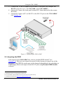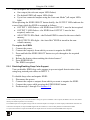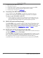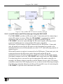
1
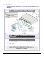
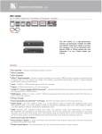
Kramer Electronics, Ltd.
USER MANUAL
Model:
VM-114H4C
2 Input 1:4 HDMI DA/4x CAT5 Outputs
Contents
Contents
1
2
2.1
3
3.1
3.2
3.3
3.4
3.5
4
5
5.1
5.2
Introduction
Getting Started
Quick Start
Overview
About HDMI—General Description
Using Shielded Twisted Pair Cable
About the Power Connect™ Feature
Defining EDID
Recommendations for Best Performance
Defining the VM-114H4C
Using the VM-114H4C
Connecting the VM-114H4C
Acquiring the EDID
5.3
5.4
Connecting to the VM-114H4C via RS-232
RS-232, IR Control and Pass-through
10
10
Wiring the Twisted Pair RJ-45 Connectors
Technical Specifications
Default Communication Parameters
Default EDID
Kramer Protocol 2000
15
15
16
16
17
5.2.1
5.4.1
5.4.2
6
7
8
9
10
Disabling/Enabling Deep Color Support
RS-232 Control and Pass-through Using the VM-114H4C
Local IR Control and IR Pass-through Using the VM-114H4C
1
1
2
3
4
4
5
5
5
6
7
7
8
9
10
11
Figures
Figure 1: VM-114H4C Front Panel
Figure 2: VM-114H4C Rear Panel
Figure 3: Connecting the VM-114H4C
Figure 4: VM-114H4C RS-232 Control and Pass-through
Figure 5: VM-114H4C IR Control and Pass-through Example One
Figure 6: VM-114H4C IR Control and Pass-through Example Two
Figure 7: VM-114H4C IR Control and Pass-through Example Three
Figure 8: CAT 5 PINOUT
6
7
8
11
12
13
14
15
i
Contents
Tables
Table 1: VM-114H4C Front Panel Features
Table 2: VM-114H4C Rear Panel Features
Table 3: Technical Specifications of the VM-114H4C
Table 4: Default Communication Parameters
Table 5: Protocol Definitions
Table 6: Instruction Codes for Protocol 2000
ii
6
7
15
16
17
18
KRAMER: SIMPLE CREATIVE TECHNOLOGY
Introduction
1
Introduction
Welcome to Kramer Electronics! Since 1981, Kramer Electronics has been
providing a world of unique, creative, and affordable solutions to the vast range of
problems that confront the video, audio, presentation, and broadcasting
professional on a daily basis. In recent years, we have redesigned and upgraded
most of our line, making the best even better! Our 1,000-plus different models now
appear in 11 groups 1 that are clearly defined by function.
Congratulations on purchasing your Kramer Desktop VM-114H4C, which is ideal
for:
• Home theater, presentation and multimedia applications
• Rental and staging
The package includes the following items:
• VM-114H4C 2 Input 1:4 HDMI DA/4x CAT5 Outputs
• Power adapter (12V DC)
• Kramer RC-IR3 infrared remote control transmitter (including the required
batteries and a separate user manual2)
• This user manual 2
2
Getting Started
We recommend that you:
• Unpack the equipment carefully and save the original box and packaging
materials for possible future shipment
• Review the contents of this user manual
• Use Kramer high performance high resolution cables 3
1 GROUP 1: Distribution Amplifiers; GROUP 2: Switchers and Matrix Switchers; GROUP 3: Control Systems; GROUP 4:
Format/Standards Converters; GROUP 5: Range Extenders and Repeaters; GROUP 6: Specialty AV Products; GROUP 7: Scan
Converters and Scalers; GROUP 8: Cables and Connectors; GROUP 9: Room Connectivity; GROUP 10: Accessories and Rack
Adapters; GROUP 11: Sierra Products
2 Download up-to-date Kramer user manuals from http://www.kramerelectronics.com
3 The complete list of Kramer cables is available from http://www.kramerelectronics.com
1
Getting Started
2.1
Quick Start
This quick start chart summarizes the basic setup and operation steps of the
VM-114H4C.
2
KRAMER: SIMPLE CREATIVE TECHNOLOGY
Overview
3
Overview
The high quality VM-114H4C is a switcher/distribution amplifier for HDMI and TP
(Twisted Pair) signals. It reclocks and equalizes one of two selectable input signals
and distributes it to four TP outputs.
In particular, the VM-114H4C:
• Supports up to 1.65Gbps bandwidth per graphic channel (DGKat) 1
• Can read and store, in non-volatile memory, the default EDID, or the EDID 2
block from one or a mix 3 of the output display devices, so it can then
provide the EDID information to the source even if the display device is not
connected
• Features I-EDIDPro™ Kramer Intelligent EDID Processing™ – Intelligent
EDID handling & processing algorithm ensures Plug and Play operation for
HDMI systems
• Supports 3D Pass-through, Deep Color 4, x.v.Color™ and uncompressed
audio channels (Dolby TrueHD, DTS-HD)
• Is HDCP compliant
• Features LEDs indicating the selected input and active output
• Supports IR remote control and has a remote IR 3.5mm mini jack
• Is 12V DC fed and is housed in a Kramer Desktop enclosure
1 Suitable for resolutions up to UXGA at 60Hz, and for all HD resolutions
2 EDID is Extended Display Identification Data (see Section 3.4 for a more detailed definition)
3 The EDID acquired is a weighted average of all the connected outputs. For example, if several displays with different resolutions are
connected to the outputs, the acquired EDID supports all the resolutions, as well as other parameters included in the EDID
4 On the HDMI input
3
Overview
3.1
About HDMI—General Description
High-Definition Multimedia Interface (HDMI) is an uncompressed all-digital 1
audio/video interface, widely supported in the entertainment and home cinema
industry. It delivers the highest high-definition image and sound quality.
In particular, HDMI 2:
• Provides a simple 3 interface between any audio/video source, such as a settop box, DVD player, or A/V receiver and video monitor, such as a digital
flat LCD/plasma television (DTV), over a single lengthy 4 cable
• Supports standard, enhanced, high-definition video, and multi-channel
digital audio 5 on a single cable
• Transmits all ATSC HDTV standards and supports 8-channel digital audio,
with bandwidth to spare to accommodate future enhancements and
requirements
• Benefits consumers by providing superior, uncompressed digital video
quality via a single cable 6 and user-friendly connector
• Is backward-compatible with DVI (Digital Visual Interface)
• Supports two-way communication between the video source (such as a
DVD player) and the digital television, enabling new functionality such as
automatic configuration and one-button play
HDMI has the capacity to support:
• Existing high-definition video formats (720p, 1080i and 1080p @60Hz), as
well as standard definition formats such as NTSC or PAL
3.2
Using Shielded Twisted Pair Cable
Kramer engineers have developed special twisted pair cables to best match our
digital twisted pair products; the Kramer: BC-DGKat524 (CAT 5 24 AWG), the
Kramer BC-DGKat623 (CAT 6 23 AWG cable), and the Kramer BC-DGKat7a23
(CAT 7a 23 AWG cable). These specially built cables significantly outperform
regular CAT 5/CAT 6 /CAT 7a cables.
1 Ensuring an all-digital rendering of video without the losses associated with analog interfaces and their unnecessary digital-to-analog
conversions
2 HDMI, the HDMI logo and High-Definition Multimedia Interface are trademarks or registered trademarks of HDMI licensing LLC
3 With video and multi-channel audio combined into a single cable, the cost, complexity, and confusion of multiple cables currently
used in A/V systems is reduced
4 HDMI technology has been designed to use standard copper cable construction at up to 15m
5 HDMI supports multiple audio formats, from standard stereo to multi-channel surround-sound. HDMI has the capacity to support
Dolby 5.1 audio and high-resolution audio formats
6 HDMI provides the quality and functionality of a digital interface while also supporting uncompressed video formats in a simple, costeffective manner
4
KRAMER: SIMPLE CREATIVE TECHNOLOGY
Overview
The VM-114H4C supports a range of up to 90m (295ft) at 1080i/SXGA or up to
30m (98ft) at 1080p/UXGA on shielded BCP-DGKat524 cable; 90m (295ft) at
1080i or up to 70m (230ft) at 1080p/UXGA on shielded BCP-DGKat623 cable.
You can daisy-chain up to six devices with the maximum overall distance between
the first and last devices being cumulative and limited by the cable type used.
3.3
About the Power Connect™ Feature
The Power Connect™ feature here means that only one unit in a system, the
transmitter or receiver, can be connected to a power source when the devices are
within 90m (270ft) of each other. The Power Connect™ feature applies as long as
the cable can carry power. The distance does not exceed 90m on standard CAT 5
cable, for longer distances, heavy gauge cable should be used 1.
!
3.4
Warning:
Using a TP cable that is incorrectly wired will
cause permanent damage to the device
Defining EDID
The Extended Display Identification Data (EDID 2) is a data-structure provided by
a display, to describe its capabilities to a graphics card (that is connected to the
display’s source). The EDID enables the VM-114H4C to “know” what kind of
monitor is connected to the output. The EDID includes the manufacturer’s name,
the product type, the timing data supported by the display, the display size,
luminance data and (for digital displays only) the pixel mapping data.
3.5
Recommendations for Best Performance
To achieve the best performance:
• Connect only good quality connection cables, thus avoiding interference,
deterioration in signal quality due to poor matching, and elevated noise
levels (often associated with low quality cables)
• Avoid interference from neighboring electrical appliances and position your
VM-114H4C away from moisture, excessive sunlight and dust
1 CAT 5 cable is still suitable for the video/audio transmission, but not for feeding the power at these distances
2 Defined by a standard published by the Video Electronics Standards Association (VESA)
5
Defining the VM-114H4C
4
Defining the VM-114H4C
Figure 1 and Table 1 define the front panel the VM-114H4C.
Figure 1: VM-114H4C Front Panel
Table 1: VM-114H4C Front Panel Features
#
1
2
3
4
5
6
7
8
9
10
Feature
IR Remote Control Sensor
IR LED
Function
Sensor for the remote control IR transmitter
Lights yellow when receiving signals from the IR remote control
transmitter
REMOTE IR 3.5mm Mini Jack
Connect to a remote infrared sensor
READ Button
Press (when one of the input LEDs is flashing to indicate a
selected input) to read the selected EDID (see Section 5.2)
EDID Buttons SELECT Button Press repeatedly to cycle through the inputs to select an input from
which to read the EDID. The relevant LED flashes (see
Section 5.2)
1
The relevant LED lights green when an acceptor is connected to
the output 1
2
OUTPUT LEDS
3
4
POWER LED
Lights green when the unit receives power
INPUT SELECTOR Button
Press to select an input. The relevant input LED lights
Lights green when HDMI input 1 is selected
IN1 (HDMI) LED
Input
LEDs
IN2 (CAT5) LED
Lights green when the TP input 2 is selected
Figure 2 and Table 2 define the rear panel VM-114H4C.
1 Also lights or flashes during EDID setup (see Section 5.2)
6
KRAMER: SIMPLE CREATIVE TECHNOLOGY
Using the VM-114H4C
Figure 2: VM-114H4C Rear Panel
Table 2: VM-114H4C Rear Panel Features
#
11
12
13
14
15
Feature
RS-232 9-pin D-sub (F)
Connector
12V DC Power Connector
IN1 (HDMI) Input
HDMI Connector
Inputs
IN2 (CAT5) Input
RJ-45 Connector
OUT 1
OUT 2
TP RJ-45 Output
Connectors
OUT 3
Function
Connect to a PC or remote controller
Connect to the +12V DC power adapter, center pin positive
Connect to an HDMI source
Connect to a TP source (for example, PT-571 HDMI Line
Transmitter, VM-114H2C or VM-114H4C)
Connect to the TP acceptors (for example, PT-572+ HDMI Line
Receiver, VM-114H or VM-114H4C)
OUT 4
5
Using the VM-114H4C
This section describes how to connect the VM-114H4C (see Section 5.1) and how
to use the EDID SELECT button (see Section 5.2).
5.1
Connecting the VM-114H4C
To connect 1 the VM-114H4C as illustrated in the example in Figure 3:
1. Connect the HDMI source (for example, a DVD player) to the IN 1 (HDMI)
connector.
2. Connect the TP source (for example, a PT-571 HDMI Line Transmitter 2,
another VM-114H2C or a VM-1114H4C) to the IN 2 (CAT5) connector.
1 Switch off the power on each device before connecting it to your VM-114H4C. After connecting your VM-114H4C, switch on its
power and then switch on the power on each device
2 Another example is the PT-573 Twisted Pair Line Transmitter
7
Using the VM-114H4C
3. Connect the TP RJ-45 outputs to up to four TP acceptors (for example, the
PT-572+ Line Receiver 1, the VM-114H or the VM-114H2C).
4. (Optional) Connect the front panel remote IR 3.5mm mini jack to the remote
IR sensor.
5. (Optional) Connect a PC via RS-232 to the RS-232 port on the VM-114H4C
(see Section 5.3).
Figure 3: Connecting the VM-114H4C
5.2 Acquiring the EDID
Each input on the VM-114H4C has a factory default EDID loaded 2 (see
Section 3.4). This lets you connect the power before having to connect one of the
acceptors. The EDID for each input can be changed independently by uploading an
EDID binary file to each input via the RS-232 port using Kramer EDID Sender
software 3.
1 Alternatively the PT-574 Twisted Pair Line Receiver
2 The VM-114H4C reads the EDID, which is stored in the non-volatile memory
3 Available for download from http://www.kramerelectronics.com
8
KRAMER: SIMPLE CREATIVE TECHNOLOGY
Using the VM-114H4C
1
You can acquire the EDID from:
• One output (the relevant output LED flashes)
• The default EDID (all output LEDs flash)
• Up to four connected outputs using the Auto-mix Mode 2 (all output LEDs
light)
When pressing the EDID SELECT button briefly, the OUTPUT LEDs indicate the
source from which the EDID is acquired as follows:
• OUTPUT 1 LED flashes—the EDID from OUTPUT 1 was the last acquired
• OUTPUT 2 LED flashes—the EDID from OUTPUT 2 was the last
acquired, and so on
• All OUTPUT LEDs flash—the Default EDID is stored in the non-volatile
memory
• All OUTPUT LEDs light—the Auto-Mix2 EDID is stored in the nonvolatile memory
To acquire the EDID:
1. Connect the power.
2. Connect the output(s) from which you want to acquire the EDID.
3. Press and hold the EDID SELECT button to cycle through to the required
output.
4. Release the button when reaching the desired source 3.
5. Press EDID READ.
The EDID is acquired.
5.2.1 Disabling/Enabling Deep Color Support
You can disable EDID deep color support to prevent signal deterioration when
using long twisted pair cables on INPUT 2.
To disable deep color and acquire EDID:
1. Disconnect the power.
2. Connect the output or outputs from which you want to acquire the EDID.
3. Connect the power while pressing the EDID READ button.
4. Perform steps 3 through 5 in Section 5.2.
1 This is usually done only once, when the machine is being set up in an installation. Once acquired, the EDID is saved in non-volatile
memory and further acquisition is not necessary
2 The EDID acquired is a weighted average of all the connected outputs. For example, if several displays with different resolutions are
connected to the outputs, the acquired EDID supports all the resolutions, as well as other parameters included in the EDID
3 If you set the machine to acquire the EDID from an output that is not connected, the default EDID will be acquired
9
Using the VM-114H4C
To enable deep color and acquire EDID:
1. Disconnect the power.
2. Connect the output or outputs from which you want to acquire the EDID.
3. Connect the power while pressing the EDID SELECT button.
4. Perform steps 3 through 5 in Section 5.2.
5.3
Connecting to the VM-114H4C via RS-232
You can connect to the VM-114H4C via an RS-232 connection using, for
example, a PC. Note that a null-modem adapter/connection is not required.
To connect to the VM-114H4C via RS-232:
• Connect the RS-232 9-pin D-sub rear panel port on the product unit via a
9-wire straight cable (only pin 2 to pin 2, pin 3 to pin 3, and pin 5 to pin 5
need to be connected) to the RS-232 9-pin D-sub port on your PC
5.4
RS-232, IR Control and Pass-through
The VM-114H4C can be controlled via RS-232 and infrared. Depending on how
the RS-232 and IR connections are configured dictates whether the device will
respond to control signals or transparently pass them through to another receiver or
transmitter. Three examples in Sections 5.4.2.1, 5.4.2.2 and 5.4.2.3 of various
configurations illustrate this functionality.
5.4.1 RS-232 Control and Pass-through Using the VM-114H4C
As shown in Figure 3, you can connect a PC (or other serial controller) directly to
the VM-114H4C to control the VM-114H4C.
The VM-114H4C also transparently passes bidirectional RS-232 signals over the
CAT 5 cable from the TP-573 transmitter to the TP-574 receiver. For example, a
PC connected to the RS-232 port on the TP-573 can control an RS-232controllable device (for example, a projection screen) connected to the TP-574.
10
KRAMER: SIMPLE CREATIVE TECHNOLOGY
Using the VM-114H4C
Figure 4: VM-114H4C RS-232 Control and Pass-through
5.4.2 Local IR Control and IR Pass-through Using the VM-114H4C
The VM-114H4C provides an IR sensor and a 3.5mm mini jack for connecting a
remote IR emitter or sensor. When the VM-114H4C is connected to suitable
transmitters and receivers (for example, the TP-573 and TP-574), the
VM-114H4C can act as a pass-through for IR control signals, allowing remote
control of multiple devices using multiple IR remote controllers.
When there is no IR sensor or emitter connected to the IR Remote 3.5mm mini
jack, all signals received by the IR sensor on the front panel are passed to the
transmitter and receiver bi-directionally over the CAT 5 cable allowing control of
remote devices.
When an IR sensor or emitter is connected to the IR Remote 3.5mm mini jack, the
connection between the IR sensor on the front panel and the IR on the
transmitter/receiver is broken so that any signal received by the IR sensor on the
front panel remains local to the VM-114H4C and controls only the VM-114H4C.
To control any device you need to use the appropriate IR remote controller, for
example, the Kramer remote controller controls Kramer devices, the LCD remote
controller controls the LCD display and so on, as shown in the following examples.
The following examples illustrate just three of the possible ways of connecting the
VM-114H4C to provide local and remote IR control.
11
Using the VM-114H4C
5.4.2.1 IR Local Control and Pass-through Example One
The configuration is shown in Figure 5.
Figure 5: VM-114H4C IR Control and Pass-through Example One
A DVD player is connected to the TP-573 transmitter via an IR emitter.
An LCD display is connected to the TP-574 receiver via an IR emitter.
Both the TP-573 and the TP-574 are connected to the VM-114H4C via TP
cabling.
To control a device, point the appropriate remote control for the device at the
VM-114H4C IR sensor.
12
KRAMER: SIMPLE CREATIVE TECHNOLOGY
Using the VM-114H4C
5.4.2.2 IR Local Control and Pass-through Example Two
The configuration is shown in Figure 6.
Figure 6: VM-114H4C IR Control and Pass-through Example Two
An IR sensor is connected to the TP-573 transmitter.
An LCD display is connected to the TP-574 receiver via an IR emitter.
Both the TP-573 and the TP-574 are connected to the VM-114H4C via TP
cabling.
To control the LCD display, point the LCD display remote control either at the
TP-573 IR sensor or at the VM-114H4C IR sensor. To control the VM-114H4C,
point the Kramer remote control at the VM-114H4C IR sensor.
13
Using the VM-114H4C
5.4.2.3 IR Local Control and Pass-through Example Three
The configuration is shown in Figure 7.
Figure 7: VM-114H4C IR Control and Pass-through Example Three
The first DVD player (player 1) is connected to the TP-573 transmitter via an IR
emitter.
The second DVD player (player 2) is connected to the VM-114H4C via an IR
emitter.
An IR sensor is connected to the TP-574 receiver.
Both the TP-573 and the TP-574 are connected to the VM-114H4C via TP
cabling.
To control DVD player 1, point the DVD player 1 IR remote control at the TP-574
IR sensor. To control DVD player 2, point the DVD player 2 IR remote control at
the TP-574 IR sensor. To control the VM-114H4C, point the Kramer remote
control at the VM-114H4C IR sensor.
14
KRAMER: SIMPLE CREATIVE TECHNOLOGY
Wiring the Twisted Pair RJ-45 Connectors
6
Wiring the Twisted Pair RJ-45 Connectors
This section defines the TP pinout, using a straight pin-to-pin cable with RJ-45
connectors.
i
Note, that the cable Ground shielding must be connected/soldered to
the connector shield.
Figure 8: CAT 5 PINOUT
EIA /TIA 568B
PIN
7
Wire Color
1
Orange / White
2
Orange
3
Green / White
4
Blue
5
Blue / White
6
Green
7
Brown / White
8
Brown
Pair 1
4 and 5
Pair 2
1 and 2
Pair 3
3 and 6
Pair 4
7 and 8
Technical Specifications
Table 3 lists the technical specifications 1 of the VM-114H4C.
Table 3: Technical Specifications of the VM-114H4C
INPUTS:
OUTPUTS:
BANDWIDTH:
COMPLIANCE WITH
HDMI STANDARD:
CONTROLS:
INDICATOR LEDs:
POWER SOURCE:
DIMENSIONS:
WEIGHT:
ACCESSORIES:
OPTIONS:
1 HDMI Connector
1 TP on an RJ-45 Connector
4 TP on RJ-45 Connectors
Supports up to 1.65Gbps bandwidth per graphic channel (DGKat)
Supports HDMI and HDCP
Input select button, EDID select button, panel lock button, RS-232, local
and remote IR controls
IR communication, Power, IN 1 HDMI, IN 2 CAT5, OUTPUT 1, 2, 3 and 4
12V DC, 2A
21.5cm x 16.3cm x 4.4cm (8.5in x 6.4in x 1.7in) W, D, H
0.9kg (1.98lbs) approx.
Power supply, RC-IR3 infrared remote control transmitter
HDMI/HDMI male to male cables, RK-1 19” rack adapter
1 Specifications are subject to change without notice
15
Default Communication Parameters
8
Default Communication Parameters
Table 4 lists the default communication parameters for the VM-114H4C.
Table 4: Default Communication Parameters
RS-232
Protocol 2000
Baud Rate:
Data Bits:
Stop Bits:
Parity:
Command Format:
Example (Output 1 to Input 1):
9
9600
8
1
None
HEX
0x01, 0x81, 0x81, 0x81
Default EDID
The factory default EDID is listed below.
Monitor
Model name............... VM114H4C
Manufacturer............. KRM
Plug and Play ID......... KRM0114
Serial number............ 505-707455010
Manufacture date......... 2009, ISO week 10
------------------------EDID revision............ 1.3
Input signal type........ Digital
Color bit depth.......... Undefined
Display type............. RGB color
Screen size.............. 520 x 320 mm (24.0 in)
Power management......... Standby, Suspend, Active off/sleep
Extension blocs.......... 1 (CEA-EXT)
------------------------DDC/CI................... n/a
Color characteristics
Default color space...... Non-sRGB
Display gamma............ 2.20
Red chromaticity......... Rx 0.674 - Ry 0.319
Green chromaticity....... Gx 0.188 - Gy 0.706
Blue chromaticity........ Bx 0.148 - By 0.064
White point (default).... Wx 0.313 - Wy 0.329
Additional descriptors... None
Timing characteristics
Horizontal scan range.... 30-83kHz
Vertical scan range...... 56-76Hz
Video bandwidth.......... 170MHz
CVT standard............. Not supported
GTF standard............. Not supported
Additional descriptors... None
Preferred timing......... Yes
Native/preferred timing.. 1280x720p at 60Hz (16:10)
Modeline............... "1280x720" 74.250 1280 1390 1430 1650 720 725 730 750 +hsync +vsync
Standard timings supported
720 x 400p at 70Hz - IBM VGA
640 x 480p at 60Hz - IBM VGA
640 x 480p at 75Hz - VESA
800 x 600p at 60Hz - VESA
800 x 600p at 75Hz - VESA
1024 x 768p at 60Hz - VESA
1024 x 768p at 75Hz - VESA
16
KRAMER: SIMPLE CREATIVE TECHNOLOGY
Kramer Protocol 2000
1280 x 1024p at 75Hz - VESA
1280 x 1024p at 60Hz - VESA STD
1600 x 1200p at 60Hz - VESA STD
1152 x 864p at 75Hz - VESA ST
10
Kramer Protocol 2000
This RS-232 communication protocol uses four bytes of information as defined
below. The default data rate is 9600 baud, with no parity, 8 data bits and 1 stop bit.
Table 5: Protocol Definitions
MSB
LSB
DESTINATION
INSTRUCTION
0
D
N5
N4
N3
N2
N1
N0
7
6
5
4
3
2
1
0
1
I6
I5
I4
I3
I2
I1
I0
7
6
5
4
3
2
1
0
1
O6
O5
O4
O3
O2
O1
O0
7
6
5
4
3
2
1
0
1
OVR
X
M4
M3
M2
M1
M0
7
6
5
4
3
2
1
0
1st byte
INPUT
2nd byte
OUTPUT
3rd byte
MACHINE NUMBER
4th byte
1st BYTE:
Bit 7 – Defined as 0.
D – “DESTINATION”:
0 - for sending information to the switchers (from the PC);
1 - for sending to the PC (from the switcher).
N5…N0 – “INSTRUCTION”
The function that is to be performed by the switcher(s) is defined by the INSTRUCTION (6 bits). Similarly, if a function is performed
via the machine’s keyboard, then these bits are set with the INSTRUCTION NO., which was performed. The instruction codes are
defined according to the table below (INSTRUCTION NO. is the value to be set for N5…N0).
2nd BYTE:
Bit 7 – Defined as 1.
I6…I0 – “INPUT”.
When switching (ie. instruction codes 1 and 2), the INPUT (7 bits) is set as the input number which is to be switched. Similarly, if
switching is done via the machine’s front-panel, then these bits are set with the INPUT NUMBER which was switched. For other
operations, these bits are defined according to the table.
3rd BYTE:
Bit 7 – Defined as 1.
O6…O0 – “OUTPUT”.
When switching (ie. instruction codes 1 and 2), the OUTPUT (7 bits) is set as the output number which is to be switched. Similarly, if
switching is done via the machine’s front-panel, then these bits are set with the OUTPUT NUMBER which was switched. For other
operations, these bits are defined according to the table.
4th BYTE:
Bit 7 – Defined as 1.
Bit 5 – Don’t care.
OVR – Machine number override.
M4…M0 – MACHINE NUMBER.
Used to address machines in a system via their machine numbers. When several machines are controlled from a single serial port, they
are usually configured together with each machine having an individual machine number. If the OVR bit is set, then all machine
numbers will accept (implement) the command, and the addressed machine will reply.
For a single machine controlled via the serial port, always set M4…M0 = 1, and make sure that the machine itself is configured as
MACHINE NUMBER = 1.
17
Kramer Protocol 2000
Table 6: Instruction Codes for Protocol 2000
Note: All values in the table are decimal, unless otherwise stated.
INSTRUCTION
DEFINITION FOR SPECIFIC INSTRUCTION
#
INPUT
1
61
62
DESCRIPTION
SWITCH VIDEO
IDENTIFY MACHINE
DEFINE MACHINE
NOTE
OUTPUT
Set equal to video input
which is to be switched
(0 = disconnect)
Set equal to video output which is 2
to be switched
(0 = to all the outputs)
1 - video machine name
3 - video software version
9 - protocol 2000 version
0 - Request first 4 digits
1 - Request first suffix
2 - Request second suffix
3 - Request third suffix
10 - Request first prefix
11 - Request second prefix
12 - Request third prefix
13
1 - number of inputs
2 - number of outputs
1 - for video
2 - for audio
14
NOTES on the above table:
NOTE 2 - These are bi-directional definitions. That is, if the switcher receives the code, it will perform the instruction; and if the
instruction is performed (due to a keystroke operation on the front panel), then these codes are sent. For example, if the HEX code
01
85
88
83
was sent from the PC, then the switcher (machine 3) will switch input 5 to output 8. If the user switched input 1 to output 7 via the front
panel keypad, then the switcher will send HEX codes:
41
81
87
83
to the PC.
When the PC sends one of the commands in this group to the switcher, then, if the instruction is valid, the switcher replies by sending to
the PC the same four bytes that it was sent (except for the first byte, where the DESTINATION bit is set high).
NOTE 13 - This is a request to identify the switcher/s in the system. If the OUTPUT is set as 0, and the INPUT is set as 1, 2, 5 or 7, the
machine will send its name. The reply is the decimal value of the INPUT and OUTPUT. For example, for a 2216, the reply to the request
to send the audio machine name would be (HEX codes):
7D
96
90
81 (i.e. 128dec+ 22dec for 2nd byte, and 128dec+ 16dec for 3rd byte).
If the request for identification is sent with the INPUT set as 3 or 4, the appropriate machine will send its software version number.
Again, the reply would be the decimal value of the INPUT and OUTPUT - the INPUT representing the number in front of the decimal
point, and the OUTPUT representing the number after it. For example, for version 3.5, the reply to the request to send the version
number would be (HEX codes):
7D
83
85
81 (i.e. 128dec+ 3dec for 2nd byte, 128dec+ 5dec for 3rd byte).
If the OUTPUT is set as 1, then the ASCII coding of the lettering following the machine’s name is sent. For example, for the VS7588YC, the reply to the request to send the first suffix would be (HEX codes):
7D
D9
C3
81 (i.e. 128dec+ ASCII for “Y”; 128dec+ ASCII for “C”).
NOTE 14 - The number of inputs and outputs refers to the specific machine which is being addressed, not to the system. For example, if
six 16X16 matrices are configured to make a 48X32 system (48 inputs, 32 outputs), the reply to the HEX code
3E
82
81
82 (ie. request the number of outputs)
would be HEX codes
7E
82
90
82
ie. 16 outputs
18
KRAMER: SIMPLE CREATIVE TECHNOLOGY
19
For the latest information on our products and a list of
Kramer distributors visit www.kramerelectronics.com
where updates to this user manual may be found.
We welcome your questions, comments and feedback.
Safety Warning:
Disconnect the unit from the power supply before
opening/servicing.
Caution
Kramer Electronics, Ltd.
Web site: www.kramerelectronics.com
E-mail: [email protected]
P/N: 2900-000645 REV 5