1
ELCD SERIES
INTRODUCTION
ALCD is Serial LCD module which is controlled through Serial communication. Most of existing LCD adopts Parallel
communication which needs lots of control lines and complicated control. On the other hand, ALCD adopts Serial
communication which needs only one or two lines to transmit data and display it on LCD. In addition, ALCD allows
users to use LCD with easy even they don’t have comprehensive knowledge of LCD module.
GENERAL DESCRIPTION
l
l
l
l
Various size from 16x2 lines to 20x4lines
3lines-interface (GND, 5V, RX)
5V level of RS232C protocol (select one of 19200 and 4800 baud rate)
Built-in functions such as location-control, screen-clear, cursor management and etc.
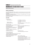
MODEL
Model
Range of display
Backlight
ELCD-162
16 BY 2
N/A
ELCD-162-BL
ELCD-164
16 BY 2
16 BY 4
LED
N/A
ELCD-164-BL
16 BY 4
LED
ELCD-204
ELCD-204-BL
20 BY 4
20 BY 4
N/A
LED
ELCD-162-BIG
16 BY 2
N/A
ELCD-162-BIG-BL
16 BY 2
LED
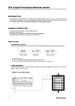
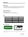
LAYOUT & OUTLINE
RX
+5V
GND
JP1
ERX
<Piicture-1> Front view
<Picture-2> Rear view
When JP1 is cut, baud rate is 4800. Otherwise, baud rate is 19200. Factory default is that JP1 is shorted. (JP1 is jumper
type in some model)
1
COMFILE Technology
ELCD SERIES
ERX is port receiving ±10V of RS232 signal directly. You can make direct control from PC with connection shown as the
following picture.
PC RS232 (9 PIN)
ELCDxxx
RX
3
+5V
2
GND
1
1
RD 2
TD 3
4
GND 5
+5V
6
7
8
9
ERX
DIMENSION
80
36
31
13.6
75
64.5
2.5PIE
ELCD162 or ELCD162-BL
ELCD164 or ELCD164-BL
98
122
93
76
24
44
37
60
55
25.2
115
99
2.5PIE
ELCD204 or ELCD204-BL
Comfile Technology
ELCD162-BIG or ELCD162-BIG-BL
2
ELCD SERIES
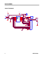
CIRCUIT DRAWING
+5V
+5V
R1
J1
R
1
2
R2
R
J2
+5V
3
2
1
CON3
4800/19200
U1
1
2
3
4
5
6
7
8
9
RA2
RA3
RTCC
MCLR
VSS
RB0
RB1
RB2
RB3
RA1
RA0
OSC1
OSC2
VDD
RB7
RB6
RB5
RB4
18
17
16
15
14
13
12
11
10
1
2
3
RESONATER
+5V
PIC16C711
+5V
X1
GND
X2
R5
1
2
3
4
5
6
7
8
9
10
11
12
13
14
15
16
VSS
VDD
VO
RS
R/W
E
B0
B1
B2
B3
B4
B5
B6
B7
A
K
R3
R
R4
R
LCD
J4
3
COMFILE Technology
ELCD SERIES
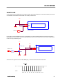
HOW TO USE
Connect 3kines connector attached to LCD module to HOST. (Microcontroller and PC can be used as HOST), and connect
5V and GND, connect RX line to TX terminal of PC or I/O port of PICmicro.
+5V
+5V
1
2
3
GND
+5V
RX
ELCD module
I/O Port
If you need to connect to RS232C port of PC or other devices, you have to organize extra level conversion circuit as the
following picture. Because that ±10V flows through RS232C line, you need to convert it into 5V level. If you use ERX port, it
is same as using the following circuit.
+5V
VCC_CIRCLE
+5V
VCC_CIRCLE
10K ohm
1
2
3
RS232C TX
GND
+5V
RX
NPN
10Kohm
ELCD module
Send 5V level of signal in the forms of 8bit, NONE parity, 1 STOP bit to RX terminal of ELCD module.
Bit Time
5V
GND
Start B0 B1
Comfile Technology
B2 B3
B4
B5 B6 B7 Stop
4
ELCD SERIES
Bit Time determines baud rate. When Bit Tine is 52mS, related baud rate is 9200. When 104mS, then 4800 baud rate. To
display characters on ELCD screen, you have to send data in the forms of command and data. For instance, when you
send LOCATE command, you have to send 0A1H, command code, first, and send two bytes of location data (X axis, Y
axis) continuously.
A0
0
0
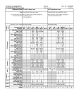
The following table describes command code and format of ELCD.
Command
(Hexadecimal)
A0
A3 01
A1 X Y
A2 String 0
Execution
time
Description
A0
1
10mS
Initialize LCD
There needs 10mS of delay at least after sending
command.
A3 01
2
Clear LCD screen
Display location is set at (0,0) automatically.
A1 01 01
3
Appoint location of display
(X axis is from 0 to 20. Y axis is from 0 to 3)
variable
Display characters on LCD screen
“0” must be sent at end of string. (End Code)
A2 41 42 00
A3 0C
A3 0C
2
Cursor OFF
A3 0E
A3 0E
2
Cursor ON (Default)
10
Eight character code, from 8 to 15, is available for
user-defined area. By sending certain BITMAP
data to the area, users can display special codes.
A4 Code Data 8
5
Transmitte
d bytes
Example
A4 08 03 01 0B
A0 AA A3 80 30
COMFILE Technology
ELCD SERIES
USAGE IN PICBASIC
Because that PICBASIC has dedicated command for control serial LCD, users don’t have to take care of LCD command
code. They can use serial LCD module with ease by only LOCATE, PRINT, CLS, etc. (Refer to PICBASIC databook for
detailed information). Refer to the following simple example.
SET PICBUS HIGH
CLS
LOCATE 0,0
PRINT “SERIAL LCD MOD.”
LOCATE 9,1
PRINT “COMFILE”
HOW TO USE USER-DEFINED AREA
ELCD has eight user-defined areas and users can stored certain BITMAP data in the area, and display on LCD screen.
In order the process, PICBASIC uses BUSOUT command. The following example show how to display arrow mark on
LCD. (BITMAP has 5*8 of size.)
SET PICBUS HIGH
LCDINIT
BUSOUT &HA5,8,0,0,0,15,15,0,0,0
BUSOUT &HA5,9,0,&H10,&H18,&H1C,&H1C,&H18,&H10,0
LOCATE 0,0
PRINT 8,9
USAGE WITH PICMICRO (ASSEMBLY LANGUAGE)
The following example is to control serial LCD by PICmicro in Assembly language. Although some devices which have
built-in UART such as PIC16C7X can make it by hardware TX function, it is recommended to make it by software. In
order to execute the following program, RX terminal of serial LCD must be connected to port0 of PORTB. (Device is
PIC16C711 using 4MHz clock)
; The delay time used in the following program is for execution at 48 baud rate, 4MHz.
: If you execute it at 19200 baud rate, you should adjust the delay time.
; When you execute the program, 16x2 of serial LCD displays follows;
;
LINE 1 : COMFILE TECHNOLO
;
LINE 2 : LCD CONTROLLER..
LIST
;
;
;
INDIR
RTCC
PC
STATUS
FSR
PORTA
PORTB
PCLATH
EQU
EQU
EQU
Comfile Technology
P=16C711, F=INHX8M
FILE DEFINITION
EQU
EQU
EQU
03H
EQU
05H
06H
EQU
00H
01H
02H
; PAGE 0
04H
0AH
6
ELCD SERIES
OPTIONR
PCL
TRISA
TRISB
VARIABLE
VARIABLE
VARIABLE
VARIABLE
VARIABLE
EQU
EQU
EQU
EQU
LOOP_CNT
BF1
DELAY_TIMER =
DELAY1_TIMER
FETCH_SEQ =
#DEFINE
01H
02H
05H
06H
=
=
0CH
0DH
=
0FH
0EH
10H
IO_TX
;
;
;
; PAGE 1
PORTB,0
BIT DEFINITION
CF
DC
ZF
PD
TO
RP0
EQU
EQU
EQU
EQU
EQU
EQU
.0
.1
.2
.3
.4
.5
; STATUS
RBIF
INTF
RTIF
RBIE
INTE
RTIE
EEIE
GIE
EQU
EQU
EQU
EQU
EQU
EQU
EQU
EQU
.0
.1
.2
.3
.4
.5
.6
.7
; INTCON REGISTER
INTEDG
RBPU
EQU
EQU
.6
.7
;
;
;
MAIN ROUTINE
ORG
GOTO
GOTO
GOTO
GOTO
0
SIJAK
SIJAK
SIJAK
SIJAK
SIJAK
RAM_CLEAR
MOVLW
MOVWF
RAM_1
CLRF
INCF
BTFSS
GOTO
BSF
MOVLW
MOVWF
7
0CH
FSR
INDIR
FSR
FSR,6
RAM_1
STATUS,RP0
B'00000000'
TRISA
COMFILE Technology
ELCD SERIES
MOVLW
MOVWF
MOVLW
MOVWF
BCF
CLRF
B'00000000'
TRISB
B'00001111'
OPTIONR
STATUS,RP0
PCLATH
;----------; MAIN PROC
;----------MOVLW
CALL
MOVLW
CALL
0A0H
TX_PROC
.200
DELAY_US
; LCD initialization command
MOVLW
CALL
MOVLW
CALL
MOVLW
CALL
0A1H
TX_PROC
00H
TX_PROC
00H
TX_PROC
; LOCATE 0,0
MOVLW
CALL
0A2H
TX_PROC
; String command (PRINT)
BTFSC
GOTO
CALL
CALL
INCF
GOTO
CLRF
MOVLW
CALL
FETCH_SEQ,4
NEXT_01
DATA0_TBL
TX_PROC
FETCH_SEQ
NEXT_0
FETCH_SEQ
00H
TX_PROC
MOVLW
CALL
MOVLW
CALL
MOVLW
CALL
0A1H
TX_PROC
00H
TX_PROC
01H
TX_PROC
MOVLW
CALL
0A2H
TX_PROC
NEXT_1
BTFSC
GOTO
CALL
CALL
INCF
GOTO
FETCH_SEQ,4
NEXT_11
DATA1_TBL
TX_PROC
FETCH_SEQ
NEXT_1
NEXT_11
CLRF
MOVLW
CALL
GOTO
FETCH_SEQ
00H
TX_PROC
MAIN_LOOP
; Enable Watch-dog ,1:8
; DELAY aroud 600US
MAIN_LOOP
LINE_0
NEXT_0
NEXT_01
; ROW 0
; COL 0
; End of string
LINE_1
Comfile Technology
8
ELCD SERIES
DATA0_TBL
MOVF
ANDWF
ADDWF
RETLW
RETLW
RETLW
RETLW
RETLW
RETLW
RETLW
RETLW
RETLW
RETLW
RETLW
RETLW
RETLW
RETLW
RETLW
RETLW
FETCH_SEQ,W
0FH
PC
'C'
'O'
'M'
'F'
'I'
'L'
'E'
''
'T'
'E'
'C'
'H'
'N'
'O'
'L'
'O'
MOVF
ANDWF
ADDWF
RETLW
RETLW
RETLW
RETLW
RETLW
RETLW
RETLW
RETLW
RETLW
RETLW
RETLW
RETLW
RETLW
RETLW
RETLW
RETLW
FETCH_SEQ,W
0FH
PC
'L'
'C'
'D'
''
'C'
'O'
'N'
'T'
'R'
'O'
'L'
'L'
'E'
'R'
'.'
'.'
MOVWF
MOVLW
MOVWF
BCF
CALL
CLRWDT
RRF
BTFSS
BCF
BTFSC
BSF
CALL
DECFSZ
GOTO
BSF
CALL
BF1
.8
LOOP_CNT
IO_TX
DELAY_ONE
DATA1_TBL
TX_PROC
TX_1
9
; Because 8BIT transmission,
BF1
STATUS,CF
IO_TX
STATUS,CF
IO_TX
DELAY_ONE
LOOP_CNT
TX_1
IO_TX
DELAY_ONE
COMFILE Technology
ELCD SERIES
RETURN
DELAY_ONE
MOVLW
;MOVLW
DELAY_US
MOVWF
DL_0
DECFSZ
GOTO
RETURN
END
; 4800-> 208US Delay(64) , 192000->52US Delay (14)
.14
; 19200 Baud Rate
.64
; 4800 Baud Rate
DELAY_TIMER
DELAY_TIMER
DL_0
USAGE WITH PICMICRO (C LANGUAGE)
If you use C language, you can control serial LCD much simpler. The following example is for controlling serial LCD by
CCS-C (PICmicro C-compiler, CCS) (Device is PIC16C711 using 4MHz clock)
#include <16c711.h>
#use delay(clock=4000000) // When 4MHz
#use rs232(baud = 19200, xmit = PIN_B1, rcv= PIN_B0)
#byte TRISB = 0x85
#byte PORTB = 5
void main()
{
char i;
TRISB = 1;
delay_ms(200);
// Wait for initialization of LCD
printf("%c%c",0xa3,0xa1);
// cls
while(1) {
printf("%c%c%c",0xa1,0,0);
// locate 0,0
printf("%cCOMFILE SERIAL %c",0xa2,0);
printf("%c%c%c",0xa1,0,1);
// locate 0,1
printf("%cLCD MODULE%d %c",0xa2,i,0);
i++;
}
}
Comfile Technology
10