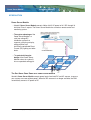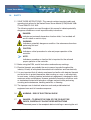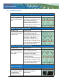
1
Power Server Module
Installation and User’s Manual
Model 1600-C2 DC Power Supply and
Model 1600-C2-24 V AUX DC Power Supply
16 Channel, Class 2, 24 VDC Output
Please contact Customer Support at 1-800-24VOLTS for further information.
Copyright 2012 all rights reserved by Nextek Power Systems, Inc. in the United States and in other countries throughout the world.
Power Server Module
Installation Manual
TABLE OF CONTENTS
ABOUT NEXTEK POWER SYSTEMS
3
INTRODUCTION / OVERVIEW
4
1.0
SAFETY
5
2.0
STANDARDS & REQUIREMENTS
6
3.0
REGULATORY INFORMATION
6
4.0
TRAINING
7
5.0
FEATURES
8
6.0
SPECIFICATIONS
9
7.0
GENERAL REQUIREMENTS
10
8.0
WARNINGS / CAUTIONS
12
9.0
INSTALLATION PROCEDURE
14
9.1 Preparing the Power Server Module for Mounting
14
9.2 Installing the Power Server Module in a Suspended
Ceiling Application
14
9.3 Installing the Power Server Module onto the Grid
15
9.4 Installing the Power Server Module in a Flat Surface
Application
16
9.5 Making the Electrical Connections for the Power Server
17
9.6 Wiring the DC AUX Input Only Included with
Model 1600-C2-24V AUX
20
9.7 Turn on Main Power
22
10.0 CONTROL AND MONITORING
23
11.0 TROUBLESHOOTING
25
12.0 NOTES
27
For more information:
2
Nextek Power Systems
461 Burroughs Street
Detroit, Michigan 48202
Tel: 313-887-1321
Toll free: 1 (877) 24-VOLTS
Fax: 313-887-9433
www.nextekpower.com
[email protected]
Copyright 2012 all rights reserved by Nextek Power Systems, Inc. in the United States and in other countries throughout the world.
Power Server Module
Installation Manual
ABOUT NEXTEK POWER SYSTEMS
Nextek Power Systems AC/DC integration technology represents a breakthrough in onsite electrical management, combining the availability of AC power with the quality and
efficiency of a DC supply.
NEXTEK PRODUCT BENEFITS
•
Easy conversion of AC lighting fixtures to DC-powered units
•
Easy conversion of AC grid power into DC power for commercial building
applications
•
Highly efficient management of peak loads
•
Future-proof lighting and other systems to be developed
•
Nextek Power Systems Direct Coupling® Technology, directly connects clean
power generated at a building to its electronic loads inside cutting down on overall power consumption, boosts electricity generated and stored on-site, and
delivers a robust renewable energy ready network.
DISCLAIMER
Nextek Power Systems has made every reasonable effort to ensure the accuracy of the
information in this catalog. Nextek Power Systems does not guarantee that the
information is error free, nor do we make any other representation, warranty or
guarantee that the information is accurate, correct, reliable or current. Nextek Power
Systems, Inc. reserves the right to make any adjustments to the information contained
herein at any time without notice. The specifications in this catalog are for reference
purposes only and are subject to change without notice. Consult Nextek Power Systems
for the latest design specifications. All trademarks are either the exclusive property of
Nextek Power Systems, Inc. or other companies. Copyright © 2012 by Nextek Power
Systems, Inc. in the United States and other countries throughout the world.
Copyright 2012 all rights reserved by Nextek Power Systems, Inc. in the United States and in other countries throughout the world.
3
Power Server Module
Installation Manual
INTRODUCTION
Power Server Module
• Nextek’s Power Server Module converts 208 or 240 V AC power to 24 V DC through 16
individual Class 2 outputs. The Power Server Module has a wireless remote control and
monitoring system.
• The system advantage of the
Power Server Module is a
safe, low-voltage DC
distribution system that
supports quick plug-and-play,
energy efficient and
individually controllable Direct
Current (DC) lighting and other
loads.
• The patented triangular
design of the Power Server
Module makes for a clean fit
into a suspended ceiling grid.
The Sun Never Goes Down on a Power Server Module
Nextek’s Power Server Module accepts power inputs from both DC and AC sources, to ensure
your systems are never without power. When the DC resource is no longer available, the PSM
automatically converts AC power to DC.
4
Copyright 2012 all rights reserved by Nextek Power Systems, Inc. in the United States and in other countries throughout the world.
Power Server Module
1.0
Installation Manual
SAFETY
1.1 SAVE THESE INSTRUCTIONS– This manual contains important safety and
operating instructions for the Nextek Power Server Module (PSM) Model 1600C2 and 1600-C2-24 V AUX.
The following symbols are used throughout this manual to indicate potentially
dangerous conditions or mark important safety instructions:
DANGER:
Indicates an imminently hazardous situation which, if not avoided, will
result in death or serious injury.
WARNING:
Indicates a potentially dangerous condition. Use extreme caution when
performing this task.
CAUTION:
Indicates a critical procedure for safe and proper operation of the
controller.
NOTE:
Indicates a procedure or function that is important for the safe and
proper operation of the controller.
1.2 Before using the PSM, read all instructions and cautionary markings.
1.3 Electrical hazards are probably the most common hazards throughout the
industry. Virtually all workplaces have electrical installations and use electricity.
1.4 It is very important that all industry employees be familiar with electrical hazards
and know how to protect themselves when working on, near, or with electricity.
In most cases, industry electrical and electronic equipment is designed for both
maximum safety and efficiency. However, potentially hazardous conditions such
as inadvertent contact with hazardous voltages may exist while performing
servicing and maintenance, handling materials, or cleaning.
1.5 The improper use of electrical extension cords and portable electrical
equipment can result in hazardous exposure.
1.6
WARNING - RISK OF ELECTRICAL SHOCK
1.7
DANGER – TO REDUCE THE RISK OF FIRE OR ELECTRIC
SHOCK, CAREFULLY FOLLOW THESE INSTRUCTIONS
1.7.1 Disconnect power to the receptacle before installing or removing the unit.
Copyright 2012 all rights reserved by Nextek Power Systems, Inc. in the United States and in other countries throughout the world.
5
Power Server Module
1.0
Installation Manual
SAFETY
When removing receptacle cover screw, cover may fall across plug pins
or receptacle may become displaced.
1.8 INSTALLATION SAFETY PRECAUTIONS
1.8.1 Mount the PSM indoors. Prevent exposure to the elements and do not
allow water to enter the unit.
1.8.2 Power connections must remain tight to avoid excessive heating from a
loose connection.
1.8.3 Use properly sized conductors and circuit interrupters.
1.8.4 The PSM output is to be connected to DC circuits only.
2.0
STANDARDS AND REQUIREMENTS
2.1 All AC and DC cable types must meet all local and national codes
2.2 Shut off all AC breakers before installing any unit into the field
2.3 Torque all the Power Server Module wire lugs and ground terminals to 16 inchpounds (1.8Nm).
2.4 AC wiring to Power Server Module
2.4.1 Use a minimum of 12 AWG, 3 conductor cables to reduce losses and
ensure high performance. The terminal block is restricted to a maximum
of 4 AWG conductor.
2.4.2 Copper wiring must be rated at 60°C or higher.
2.4.3 A disconnect device must be incorporated in the field wiring.
2.4.4 The Power Server Module must be protected by a circuit breaker.
3.0
REGULATORY INFORMATION
NOTE: This section contains important information for safety and
regulatory requirements.
3.1 The PSM should be installed by a qualified technician according to the electrical
rules of the country in which the product will be installed.
3.2 Nextek PSM units comply with the following EMC standards:
6
3.2.1 UL 2043
3.2.4 UL 2577
3.2.2 UL 1310
3.2.5 ROHS
3.2.3 UL 1012
3.2.6 EMerge
Copyright 2012 all rights reserved by Nextek Power Systems, Inc. in the United States and in other countries throughout the world.
Power Server Module
3.0
Installation Manual
REGULATORY INFORMAITON
3.3 FCC Requirements:
This device complies with Part 15 of the FCC rules. Operation is subject to the following two
conditions: (1) This device may not cause harmful interference, and (2) this device must accept
any interference received, including interference that may cause undesired operation.
Changes or modifi cations not expressly approved by Nextek Power Systems, Inc. for
compliance could void the user’s authority to operate the equipment.
Note:
This equipment has been tested and found to comply with the limits for a Class B digital device,
pursuant to Part 15 of the FCC rules. These limits are designed to provide reasonable protection
against harmful interference in a residential installation. This equipment generates, uses, and
can radiate radio frequency energy and, if not installed and used in accordance with the
instruction manual, may cause harmful interference to radio communication. However, there is
no guarantee that interference will not occur in a particular installation. If this equipment does
cause harmful interference to radio or television reception, which can be determined by turning
the equipment on and off, the user is encouraged to try to correct the interference by one or
more of the following measures:
4.0
•
Reorient or relocate the receiving antenna.
•
Increase the separation between the equipment and receiver.
•
Connect the equipment into an outlet on a circuit different from that to which the receiver is
connected.
•
Consult the dealer or an experienced radio/TV technician for help.
INSTALLATION QUALIFICATIONS
4.1 Installation work and electrical wiring of permanently-connected power units
must be performed only by qualified service personnel in accordance with all
applicable codes and standards, including fire-rated construction.
Copyright 2012 all rights reserved by Nextek Power Systems, Inc. in the United States and in other countries throughout the world.
7
Power Server Module
5.0
Installation Manual
POWER SERVER MODULE FEATURES
• Patented triangular design makes for a
clean fit into a suspended ceiling grid for
ease of installation and removal of
ceiling tiles.
• Easy conversion of AC lighting fixtures
to DC-powered systems
• Easy conversion of AC grid power into
DC power for commercial building
applications
• Highly efficient management of peak
loads
• Converts 208 or 240 VAC power to 24
VDC through 16 individual Class 2
outputs. Includes a wireless remote
control and monitoring system
• Complete continuity of alternative
energy sources such as PV, micro
turbines and fuel cells
• Safe, low-voltage DC distribution that
allows quick plug-and-play, energy
efficient and individually controllable DC
lighting and other loads
• Complete continuity of supply through
the seamless integration of available
rechargeable batteries
AC wire
knockouts
DC wire
knockouts
• Unlike conventional installations utilizing
DC to AC inverters that must be shut
down in the event of a grid power failure
(anti-islanding), the Nextek system can
stay on and continue to support the DC
loads by combining all available DC
sources.
Channels 1-16
output terminals
ZigBee
communication
System
status
Wireless
antenna
Power LED
Mounting
feet
Mounting
feet
8
Fan
Copyright 2012 all rights reserved by Nextek Power Systems, Inc. in the United States and in other countries throughout the world.
Power Server Module
6.0
Installation Manual
TECHNICAL SPECIFICATIONS
• UL2043 - Fire Test for Heat and Visible Smoke
Release for Discrete Products and Their
Accessories Installed in Air-Handling Spaces
• UL1310 - Class 2 Power Units
• UL1012 - Power Units Other Than Class 2
• UL2577 - Suspended Ceiling Grid Low Voltage
Lighting Systems
• EmergeAlliance® Registered
• RoHS compliant
MECHANICAL
Dimensions
Weight
Mounting Orientation
Audible Noise
Operational Environmental Limits
Storage Environmental Limits
Construction
Installation
PSM 1600-C2 and 1600-C2-24V AUX
see diagram above
21.1 lbs.
Flat horizontal surface – using rubber feet
Ceiling grid – using plastic grid interconnects
Less than 15 dBA
Temperature Range: 0° to 49°C
Humidity: 90% RH non-condensing
Vibration: Low-Frequency 10-55 Hz
Temperature Range: -40° to 60°C
Humidity: 95% RH non-condensing
(transport and storage in protective container)
Vibration: Low-Frequency 10-55 Hz
Made of 20 gauge steel, manufactured in U.S.A.
When installed in a suspended ceiling, installation requires a
minimum of 12” from the top of the ceiling grid to the deck.
ELECTRICAL
Input Power
AUX Input Power
Output Per Channel
208 – 240 VAC single phase, 13.5 A max., 50/60 HZ
24.0 – 24.5 VDC, 65 A max.; Model 1600-C2-24V AUX only
24 VDC ± 5%
95 W maximum current limited to 3.96 A continuous
Rated impulse current – 80 A for .2 mSec
Efficiency
Quiescent power = 7W; 90% @ 240 VAC input; 1500 W output
Wireless Communication
Provided through a ZigBee® module series (XBee Series2®)
and a Nextek Power Systems software interface (PS Manager).
See PS Manager manual for functionality and usage.
Copyright 2012 all rights reserved by Nextek Power Systems, Inc. in the United States and in other countries throughout the world.
9
Power Server Module
7.0
Installation Manual
GENERAL REQUIREMENTS
7.1 Every work environment should provide a safe place for every employee, which
includes protecting the employee from electrical hazards such as fault currents
to ground.
7.2 When an electrical ground fault occurs, the current flows through the path
having minimum impedance to ground. It is imperative that an employee does
not inadvertently become the conductor of the current.
7.3 Two approved methods of protecting the worker from a ground fault, in addition
to other requirements for equipment-grounding conductors, are:
7.3.1 Use of ground fault circuit interrupters (GFCI)
7.3.2 An assured equipment grounding conductor program
7.4 Installers should be advised:
7.4.1 These installation instructions are for use by qualified personnel only.
NOTE: Installers must reference the National Electric Code (NEC)
sections
250 or 690, when required, to ensure proper system wiring and
7.4.2 The equipment contains DC voltages.
grounding compliance. In addition, all state and federal Occupational
Safety and Health Administration (OSHA) guidelines and regulations
must be followed.
NOTE: Installers must reference the specific site scope and project
drawings
for additional information and considerations, including the
system layout and any related electrical drawings.
7.4.3 The mounting location is important to the performance and operating life
of the controller. The environment must be dry and protected from water
ingress. If required, the controller may be installed in a ventilated
enclosure with sufficient air flow. Never install the PSM in a sealed
enclosure.
7.4.4 The installation is straightforward, but it is important each step is done
correctly and safely. A mistake can lead to dangerous voltage and
current levels. Be sure to carefully follow each instruction in this section.
Read all instructions first before beginning installation.
7.4.5 The installation instructions are for installation of a negative grounded
system. National Electrical Code (NEC) requirements are noted on
occasion for convenience, however the installer should have a complete
understanding of NEC and UL requirements for photovoltaic installations.
10
Copyright 2012 all rights reserved by Nextek Power Systems, Inc. in the United States and in other countries throughout the world.
Power Server Module
7.0
Installation Manual
GENERAL REQUIREMENTS
7.5 Recommended Tools
7.5.1 Standard construction and electrical tools along with basic electrical
safety and testing instruments are required for the installation of the
combiner box. This installation requires the following:
#2 and #0 Phillips screwdriver
7/16" wrench
Torque wrench (inch-pounds)
Wire strippers
Copyright 2012 all rights reserved by Nextek Power Systems, Inc. in the United States and in other countries throughout the world.
11
Power Server Module
8.0
Installation Manual
WARNINGS / CAUTIONS
WARNING - Shock Hazard
8.1 The Nextek Power Server Module AC connection should only be performed by
trained service personnel.
8.2 The Nextek Power Server Module is designed to keep its external surface
temperature from rising more than 30°C above the ambient temperature.
8.3 Treat any conductors and parts of electric equipment as energized that have
been de-energized, but have not been properly locked or tagged out and tested
to a zero energy state.
LOCKOUT/TAGOUT MUST ALWAYS BE USED.
8.4 Nextek Power Server Module specifications:
Outputs: 24 VDC, 95 VA per channel for 16 channel(s)
AC Inputs: 208 - 240 VAC, 50/60 Hz
For 277 VAC, a Nextek Power Systems’ Auto-Transformer Model
NOTE:
277-240AT or equivalent is required. (see Section 7.6 for 277 VAC
DC input: 24.0 – 24.5 VDC Max – Only included with Model 1600-C2-24V AUX
connection).
8.5 AC connections are made inside the Nextek Power Server
Module at the terminal blocks.
8.6 The Nextek Power Server Module does not come with the AC supply
cable. AC supply must be provided from 3 conductors of 12 AWG minimum.
Refer to Table 8.1 for list of acceptable equivalent cords. The terminal block is
restricted to a maximum of 4 AWG conductor.
Basic Cord Type Other Suitable Types
TS TST
SP-2 SPE-2, SPT-2
SP-3 SPE-3, SPT-3
SV SVE, SVO, SVOO, SVT, SVTO, SVTOO
SJ SJE, SJO, SJOO, SJT, SJTO, SJTOO
SE SE, SO, SOO, ST, STO, STOO
Table 8.1 Suitable Cord Types
12
Copyright 2012 all rights reserved by Nextek Power Systems, Inc. in the United States and in other countries throughout the world.
Power Server Module
8.0
Installation Manual
WARNINGS / CAUTIONS
8.7 There are no operator adjustable voltage selectors in this system for 24 VDC.
8.8 To complete the assembly, the mounting legs must be installed prior to grid
installation. Follow installation procedure to install and power up the system.
Copyright 2012 all rights reserved by Nextek Power Systems, Inc. in the United States and in other countries throughout the world.
13
Power Server Module
9.0
Installation Manual
INSTALLATION PROCEDURE
9.1 Preparing the Power Server Module for Mounting
9.1.1 Turn off all main power before starting this project, using the Lock Out
Tag Out method. Refer to the facility electrical drawings to identify the
mounting locations and any specific electrical location requirements or
special instructions. You must mount the Power Server Module in an easy
accessible position/location.
9.1.2 In the shipping container there
are:
• (4) mounting legs
• (8) 1/4” nuts
• (1) front panel cover
• (4) overhead drop ceiling grid
mounting clips
• (4) rubber table top feet
9.1.3 Attach the mounting legs to the
Nextek Power Server Module by
sliding the legs over the side wall
studs.
9.1.4 Place the nut onto each stud and
hand tighten using a 7/16" wrench.
Torque all (8) 1/4" nuts to 48 inchpounds (5.4 Nm)
9.1.5 Attach the mounting legs to the Nextek Power
Server Module in four locations.
9.2 Installing the Power Server Module in a Suspended Ceiling Application
9.2.1 Specifications for Suspended Ceiling Mating shall be as follows:
9.2.1.1 The grid shall be rated “Heavy Duty” in conformance to ASTM
C635.
9.2.1.2 The material of construction shall be hot-dipped galvanized
steel.
14
Copyright 2012 all rights reserved by Nextek Power Systems, Inc. in the United States and in other countries throughout the world.
Power Server Module
9.0
Installation Manual
INSTALLATION PROCEDURE
9.2.1.3 The grid shall be capable of supporting four times (4X) the
weight of this unit.
9.2.1.4 The top section of the grid to
which the plastic feet clips mate
shall be nominally 0.250 inches
wide and 0.625 inches high.
See Figure 9.2.
9.2.1.5 The suspended grid system
should be installed in
conformance to ASTM C636
9.3 Installing the Power Server Module onto the Grid
9.3.1 When installed in a suspended ceiling,
Figure 9.2
installation requires a minimum of 12”
from the top of the ceiling grid to the deck, dependent on adjacent
obstructions.
9.3.2 Place the Power Server Module on the ceiling grid channel. Mark the
location of the stands on the grid with a marker. Lift the Power Server
Module up and place the clips in the marked location. Bring the Power
Server Module back to original position such that the Power Server
Module legs will be right over the clips. Press down on the Power Server
Module to snap in place.
CAUTION: WHEN PLACING THE POWER SERVER ON THE CEILING
GRID, ENSURE THAT TWO OF THE LEGS ARE MOUNTED ON A
MAIN BEAM FOR THE CEILING GRID WHILE THE OTHER TWO LEGS
ARE MOUNTED ON A CROSS GRID BEAM.
Main Power Grid
*
*
*
*
NOT APPROVED:
Mounting locations incorrect.
2 legs are not on a main
power rail with hanger wire.
APPROVED:
Mounting locations correct. 2
legs are on a main power rail
with hanger wire.
* Hanger wire location
Copyright 2012 all rights reserved by Nextek Power Systems, Inc. in the United States and in other countries throughout the world.
15
Power Server Module
9.0
Installation Manual
INSTALLATION PROCEDURE
9.3.3 The Power Server Module can be mounted onto the rail at a distance of
4.063” from the main railing Tee-To-Tee connection.
9.3.4 Position of Power Server Module installation is in accordance with
suspension system installed to ASTM C636.
9.3.5 If required by local zoning laws, the following mounting attachment points
can be used:
9.3.5.1 One (1) hanger wire (suspension wire) of 10 to 12 gauge soft
annealed wire can be used on top of each leg.
9.3.5.2 One (1) hanger wire shall be attached to every other leg of the
Power Server Module and attached to the overhead bracing
structure above. These wires are taut or tight as required by
local zoning ordinance. Refer to the image below:
9.3.5.3 Another hanger wire shall be attached to every other leg of the
Power Server Module and attached to the drop ceiling grid
below. These wires are tight or taut as required by local zoning
ordinance. Refer to the image below:
9.3.5.4 All wire ties are to be three tight turns around itself within three
inches. Refer to the image below:
Minimum 3 twists
Minimum 3"
(76mm)
Connects to drop
ceiling grid
9.3.5.5 Must conform with all local and other authorities having jurisdiction.
9.4 Installing the Power Server Module in a Flat Surface Application
9.4.1 Install the rubber feet onto the bottom of the legs.
CAUTION: WHEN PLACING THE POWER SERVER ON A TABLE OR
FLAT SURFACE, ENSURE THAT THE PLASTIC CLIPS ARE NOT
USED AND THE RUBBER FEET ARE PLACED OVER THE BOTTOM
OF THE LEGS TOUCHING THE TABLE TOP.
16
Copyright 2012 all rights reserved by Nextek Power Systems, Inc. in the United States and in other countries throughout the world.
Power Server Module
9.0
Installation Manual
INSTALLATION PROCEDURE
9.5 Making the Electrical Connections for the Power Server
The power server module may be wired directly to 208 or 240 VAC
service
only. For 277 VAC service, the Power Server Module
NOTES:
1.
colors listed below are provided as guidance only for
Conductor
installations in the United States. It is the installer’s responsibility
should be ordered as the 277 Volts Input PSM 1600-C2 *Auto
Transformer Included* as described in section 9.5.3
2.
to follow all local and national codes.
9. 5.1 For 208 VAC service
NOTE: NO NEUTRAL: There is no Neutral (usually White or
Gray) conductor required for 208 VAC service. If a Neutral
conductor exists in the cable, it must be capped off and not used
BOTH at the Power Server AND at the circuit breaker panel.
9.5.1.2 A 2-pole single throw breaker must be used at the breaker panel
to ensure that if the breaker trips, both L1 and L2 are not live at
the Power Server Module.
9.5.1.3 Remove 4 screws from left side
front panel and remove the panel.
9.5.1.4 Insert AC cable through hole on top left side
of the Power Server Module. Use a flex
relief/clamp (not provided) to position the
cable in hole and to protect it from sharp
edges.
9.5.1.5 The supply circuit shall contain two of the three phases of a
208Y VAC service (Usually Black, Red or Blue) and one Earth
Ground conductor (usually Green). Connect one of the AC
phases to the terminal block located inside the open panel to the
position marked L1 and the other AC phase to L2. It does not
matter which phase goes to L1 or L2. Connect the Earth Ground
conductor to the Terminal Block at the position marked GND.
Copyright 2012 all rights reserved by Nextek Power Systems, Inc. in the United States and in other countries throughout the world.
17
Power Server Module
9.0
Installation Manual
INSTALLATION PROCEDURE
9.5.1.6 Torque all (3)
terminal block set
screws to 16 inchpounds (1.8Nm).
9.5.1.7 Replace the front panel with four
screws.
9.5.2 For 240 VAC Service
NOTE: NO NEUTRAL: There is no Neutral (usually White or
Gray) conductor required for 240 VAC service. If a Neutral
conductor exists in the cable, it must be capped off and not used
BOTH at the Power Server AND at the circuit breaker panel.
9.5.2.1 A 2-pole single throw breaker must be used at the breaker panel
to ensure that if the breaker trips, both L1 and L2 are not live at
the Power Server Module.
9.5.2.2 Remove 4 screws from left side
front panel and remove the panel.
9.5.2.3 Insert AC cable through hole on top left side
of the Power Server Module. Use a flex
relief/clamp (not provided) to position the
cable in hole and to protect it from sharp
edges.
9.5.2.4 The supply circuit shall contain two of the three phases of a
208Y VAC service (Usually Black or Red) and one Earth Ground
conductor (usually Green). Connect one of the AC phases to the
terminal block located inside the open panel to the position
marked L1 and the other AC phase to L2. It does not matter
18
Copyright 2012 all rights reserved by Nextek Power Systems, Inc. in the United States and in other countries throughout the world.
Power Server Module
9.0
Installation Manual
INSTALLATION PROCEDURE
which phase goes to L1 or L2. Connect the Earth Ground
conductor to the Terminal Block at the position marked GND.
9.5.2.5 Torque all (3)
terminal block set
screws to 16 inchpounds (1.8Nm).
9.5.2.4 Replace the front panel with four
screws.
9.5.3 For 277 VAC Service
9.5.3.1 The PSM cannot connect to 277 VAC directly at this time.
Instead, Power Servers meant for connection to 277 VAC should
be ordered as a 277 Volts Input PSM 1600-C2 *Auto
Transformer Included*.
9.5.3.2 Follow the Installation Instructions that came with the Nextek
AutoTransformer Model 277-240AT. [The two hot outputs of the
Auto-Transformer L1/3 and L4 and the Ground wire will be the
inputs to the Power Server Module.]
9.5.3.3 A 2-pole single throw breaker must be used at the breaker panel
in front of the Nextek Auto-Transformer to ensure that if the
breaker trips, both L1 and L2 are not live at the Nextek AutoTransformer and Power Server Module.
9.5.3.4 Remove 4 screws from left side
front panel and remove the panel.
Copyright 2012 all rights reserved by Nextek Power Systems, Inc. in the United States and in other countries throughout the world.
19
Power Server Module
9.0
Installation Manual
INSTALLATION PROCEDURE
9.5.3.5 Insert AC cable from Nextek Auto-Transformer
Model 277-240AT through hole on top left side
of the Power Server Module. Use a flex
relief/clamp (not provided) to position the
cable in hole and to protect it from sharp
edges.
9.5.3.6 The two hot outputs of the Auto-Transformer L1/3 and L4 and
the Ground wire will be the inputs to the Power Server Module.
Connect these two hot wires from the Auto-Transformer (L1/3
and L4) to the terminal block located inside the open panel to
the positions marked L1 and L2 on the Power Server Module. It
does not matter which wire goes to L1 or L2. Connect the Earth
Ground conductor from the Auto-Transformer to the Terminal
Block at the position marked GND on the Power Server module.
9.5.3.7 Torque all (3)
terminal block set
screws to 16 inchpounds (1.8Nm).
9.5.2.4 Replace the front panel with four
screws.
9.6
Wiring the DC AUX Input Only Included with Model 1600-C2-24V AUX
WARNINGS:
AUX input must not be capable of sinking current from the Power
Server Module.
The input is unidirectional and cannot be used as an output.
A battery cannot be directly connected to the AUX input terminals.
Caution at the DC terminals must be taken because up to 75 amps
of current is available to back feed at the AUX input terminals.
20
Copyright 2012 all rights reserved by Nextek Power Systems, Inc. in the United States and in other countries throughout the world.
Power Server Module
9.0
Installation Manual
INSTALLATION PROCEDURE
Two conductor cables rated for 80 amps must be used.
Only use Nextek Power Systems approved equipment that has back
feed prevention capability.
9.6.1 Remove 4 screws from left side front panel
and remove the panel.
9.6.2 Insert D.C. wiring through hole on the top right side of
Power Server Module Use a flex relief/clamp (not
provided) to position the cable in hole and to protect it
from sharp edges.
9.6.3 Connect the two DC supply wires to the terminal block located inside the
open panel in the following order: Negative (Black) AUX-, Positive (Red)
AUX+. The input is rated for 24.0 – 24.5 VDC, 65 A max.
NOTES:
Torque both terminal set screws to 16 inch-pounds (1.8Nm).
Color of insulation on the wires may differ.
No Neutral connection is required.
If an additional conductor is present, cap off
the wire inside the Power Server Module and
circuit breaker or local junction box.
9.6.4 The Power Server Module has an 80 amp single pole circuit breaker
mounted on the front panel which disconnects the DC input supply from
the AUX inputs only. Make sure the breaker is set to “On” before using the
AUX as a source.
9.6.5 Replace the front panel with four screws.
Copyright 2012 all rights reserved by Nextek Power Systems, Inc. in the United States and in other countries throughout the world.
21
Power Server Module
9.0
Installation Manual
INSTALLATION PROCEDURE
9.7 Turn on Main Power.
(Go to section 10.0 Controls and Monitoring for start up mode and system checks.)
9.7.1 Channel Status (LEDs check):
Green – ON
Off – OFF
Red – Over current
Orange – Short circuit
9.7.2 Power ON light:
Green – ON
Off – OFF
9.7.3 System Status lights:
Flashing Green – OK
Flashing Red – System
fault
9.7.4 Zigbee Associate lights:
Orange – Not associating
Flashing – Associating
9.7.5 Rectifier Status:
Green – System running
Red – System in standby – startup /
shutdown mode
Off – Off
NOTES:
9.7.6 The Power Server Module has 16 channels. Each channel delivers 95 VA
continuous.
The Power Server Module total power output is rated to 1520W max.
Each output channel is connected to a single section of a grid using a
server to grid cable (not provided).
If two channels are connected to a single grid, then both channels will be
automatically turned off, until the problem has been corrected.
22
Copyright 2012 all rights reserved by Nextek Power Systems, Inc. in the United States and in other countries throughout the world.
Power Server Module
10.0
Installation Manual
CONTROL AND MONITORING
10.1 PC-Based Monitoring and Control
10.1.1 To install the enclosed Zigbee USB stick, please use the following files
included on the enclosed disc:
Install Zigbee
How to Install a Zigbee USB Stick and Run PS Manager
Zigbee USB Stick Drivers – Windows Vista and Beyond
Zigbee USB Stick Drivers – Windows XP
10.1.2 To install and run the enclosed PS Manager monitoring and control
software, please use the following files:
PSmanager_Setup_version.exe to install PS Manager on the computer
PS Manager Software Guide for instructions on how to use PS Manager.
10.1.3 PS Manager software is available for controlling and monitoring the
output of each channel independently. Monitoring and reporting the state
of the inputs and outputs is as follows:
10.1.3.1 Channel Status (OK, Disabled, Inrush, Over current, Short
Circuit)
10.1.3.2 Channel Load in Watts
10.1.3.3 Channel output voltage max since last poll
10.1.3.4 Channel output voltage low since last poll
10.1.3.5 Channel output current max since last poll
10.1.3.6 Channel output current low since last poll
10.1.3.7 Graphical representation of each output with respect to both
voltage and power
10.1.3.8 Input Currents (Rectifier) provision for measurement will be
provided for total-input current sensors
10.1.3.9 Housekeeping voltages
10.1.3.10 Internal power supply voltages
10.2 Start-Up System Check
Output status LEDs labeled and located adjacent to their respective output.
System startup check as follows:
10.2.1
Turn power on to the Power Server Module
Copyright 2012 all rights reserved by Nextek Power Systems, Inc. in the United States and in other countries throughout the world.
23
Power Server Module
10.0
Installation Manual
CONTROL AND MONITORING
10.2.2
Channels 1–16: flicker on at different colors
10.2.3
3 beeps at 1 second intervals.
10.2.4
Channels 1–16: all turn green on
10.2.5
Channels 1–16: sequentially turn off and stay off
10.2.6
Channels 1–16: all turn off
10.2.7
Channels 1–16: sequentially turn red and stay red
10.2.8
Channels 1–16: all turn red on
10.2.9
Channels 1–16: sequentially turn red off and stay off
10.2.10 Channels 1–16: all turn off
10.2.11 Channels 1–16: flash green on then off sequentially
10.2.12 Channels 1–16: all turn off
10.2.13 Channels 1–16: all green (System OK)
24
Copyright 2012 all rights reserved by Nextek Power Systems, Inc. in the United States and in other countries throughout the world.
Power Server Module
11.0
Installation Manual
TROUBLESHOOTING
11.1 Visual Status Display
System status is indicated by 4 different types of LED indicators on the master
controller as follows:
11.1.1 Power LED:
Green – On
Off – Off
11.1.2 System Status:
Flashing Green – On
Flashing Red – Signifies an error
11.1.3 Zigbee Association:
Orange – Not associating
Flashing Orange – Associating
11.1.4 Channel Status:
Off – Off
Green – On
Orange – Over current
Red – Short circuit
11.2 Common Problems
Problem: Power LED off
Possible Casue
Possible Solution
No power going to the
Power Server Module.
• Check to make sure the power
feed cable wires are connected to
the terminal block under the front
cover.
No power going to the
Power Server Module.
• Check to make sure the LED on
the back of the housing is green.
• Circuit Breaker to the Power
Server Module is tripped.
Copyright 2012 all rights reserved by Nextek Power Systems, Inc. in the United States and in other countries throughout the world.
25
Power Server Module
11.0
Installation Manual
TROUBLESHOOTING
Problem: System Status LED Flashing Red
Possible Casue
Possible Solution
One of the channels has • Check the channel status LEDs to
an issue with the output
ensure that all are green. If one is
load.
red or orange, remove the
connector from the Power Server
Module and check the load.
• If PS Manager is available, review
the status of each channel.
Problem: Channel Status LED Red
Possible Casue
Possible Solution
One of the channels has • Remove the load from the Power
a short circuit issue with
Server Module channel by
the output load.
disconnecting the connector. If the
channel LED turns green, check
the load for a short circuit.
• If the channel LED remains red,
then call Nextek Customer Service.
• If PS Manager is available, review
the status of each channel.
Problem: Channel Status LED Orange
Possible Casue
Possible Solution
One of the channels has • Remove the load from the Power
exceeded the maximum
Server Module channel by
power output capacity of
disconnecting the connector. If the
the channel.
channel LED turns green,
redistribute the load to prevent an
over load condition.
• If the channel LED remains orange,
then call Nextek Customer Service.
• If PS Manager is available, review
the status of each channel
Problem: As additional loads are connected to the Power Server Module, it
causes a shut down.
Possible Casue
Possible Solution
The main power feed to • Check to ensure the main power
the Power Server Module feed meets the required
may be below the
specifications.
required specification.
26
Copyright 2012 all rights reserved by Nextek Power Systems, Inc. in the United States and in other countries throughout the world.
Power Server Module
12.0
Installation Manual
NOTES
Copyright 2012 all rights reserved by Nextek Power Systems, Inc. in the United States and in other countries throughout the world.
27
For more information:
Nextek Power Systems
461 Burroughs Street
Detroit, Michigan 48202
www.nextekpower.com
Tel: 313-887-1321
Toll free: 1 (877) 24-VOLTS
Fax: 313-887-9433
[email protected]