1
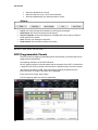
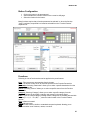
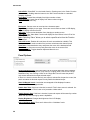
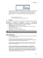
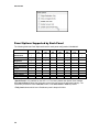
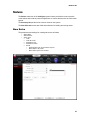
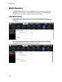
SIERRA VIDEO Mediator-EC 934001-00 User’s Manual Mediator-EC® SYSTEM CONTROL User’s Manual Sierra Video P.O. Box 2462 Grass Valley, CA 95945 Tel: (530) 478-1000 Fax: (530) 478-1105 Email: [email protected] Version 1.01 Publication Date: January 2013 The information contained in this manual is subject to change by Sierra Video Regulatory Warnings & Safety Information The information in the following section provides important warnings and safety guidelines for both the operator and service personnel. Specific warnings and cautions may be found throughout this manual. Please read and follow the important safety precautions noting especially those instructions relating to risk of fire, electrical shock and injury to persons. Any instructions in this manual that require opening the equipment cover or enclosure are intended for use by qualified service personnel only. To reduce the risk of electrical shock, do not perform any servicing other than what is contained in the operating instructions unless you are qualified. Warnings Heed all warnings on the unit and in the operating instructions. Disconnect AC power before installing or removing device or servicing unit. Do not use this product in or near water. This product is grounded through the grounding conductor of the power cord. To avoid electrical shock, plug the power cord into a properly wired receptacle before connecting inputs or outputs. Route power cords and other cables so that they are not likely to be damaged, or create a hazard. Dangerous voltages exist at several points in this product. To avoid personal injury, do not touch unsafe connections and components when the power is on. Have qualified personnel perform safety checks after any completed service. To reduce risk of electrical shock, be certain to plug each power supply cord into a separate branch circuit employing a separate service ground. Operate only with covers and enclosure panels in place – Do Not operate this product when covers or enclosure panels are removed. This is an FCC class A product. In a domestic environment, this product may cause radio interference, in which case the user may be required to take necessary measures. Use the proper AC voltage to supply power to the controller frame. When installing equipment, do not attach the power cord to building surfaces. Cautions Sierra Video Cautions (continued) Use only the recommended interconnect cables to connect the controller to other frames. Follow static precautions at all times when handling the equipment. Power this product only as described in the installation section of this manual. Leave the sides of the frame clear for air convection cooling and to allow room for cabling. Slot and openings in the frame are provided for ventilation and should not be blocked. Only an authorized Sierra Video technician should service the unit. Any user who makes changes or modifications to the unit without the expressed approval of Sierra Video will void the warranty. If installed in a closed or multi-unit rack assembly, the operating ambient temperature of the rack environment may be greater than the room ambient temperature. Therefore, consideration should be given to installing the equipment in an environment compatible with the manufacturer’s maximum rated ambient temperature (TMRA). Installation of the equipment in a rack should be such that the amount of air flow required for safe operation of the equipment is not compromised. Other connections between peripherals of this equipment may be made with low voltage non-shielded computer data cables. Network connections may consist of non-shielded CAT 5 cable. FCC Notice This equipment has been tested and found to comply with the limits for a Class A digital device, pursuant to Part 15 of the FCC rules. These limits are designed to provide reasonable protection against harmful interference when the equipment is operated in a commercial environment. This equipment generates, uses, and can radiate radio frequency energy and, if not installed and used in accordance with the instruction manual, may cause harmful interference to radio communications. Operation of this equipment in a residential area is likely to cause harmful interference in which case the user will be required to correct the interference at the expense of the user. The user may find the following publication prepared by the Federal Communications Commission helpful: “How to Identify and Resolve Radio-TV Interference Problems” (Stock number 004-000-00345-4). Available exclusively from the Superintendent of Documents, Government Printing Office, Washington, DC 20402 (telephone 202 512-1800). Warning Changes or modifications not expressly approved by the party responsible for compliance to Part 15 of the FCC Rules could void the user’s authority to operate the equipment. Mediator-EC Power Supply Cords Use only power cord(s) supplied with the unit. If power cord(s) were not supplied with the unit, select as follows: For units installed in the USA and Canada: select a flexible, three-conductor power cord that is UL listed and CSA certified, with individual conductor wire size of #18 AWG, and a maximum length of 4.5 meters. The power cord terminations should be NEMA Type 5-15P (three-prong earthing) at one end and IEC appliance inlet coupler at the other end. Any of the following types of power cords are acceptable; SV, SVE, SVO, SVT, SVTO, SVTOO, S, SE, SO, SOO, ST, STO, STOO, SJ, SJE, SJO, SJOO, SJT, SJTOO, SP-3, G, W. For units installed in all other countries; select only a flexible, three-conductor power cord, approved by the appropriate safety organization of your country. The power cord must be Type HAR (Harmonized), with individual conductor wire size of 0.75 mm². The power cord terminations should be a suitably rated earthing-type plug at one end and IEC appliance inlet coupler at the other end. Both of the power cord terminations must carry the certification label (mark) of the cognizant safety organization of your country. A non-shielded power cord may be used to connect AC power to every component and peripheral of the system. Connect an external 16 AWG or larger wire from earth ground to the chassis of the system as designated by the earth ground symbol. North American Power Supply Cords This equipment is supplied with North American power cords with molded grounded plug (NEMA15P) at one end and molded grounding connector (IEC 320-C13) at the other end. Conductors are CEE color coded, light blue (neutral), brown (line), and green/yellow (ground). Operation of the equipment at voltages exceeding 130VAC will require power supply cords that comply with NEMA configurations. International Power Supply Cords If shipped outside North America, this equipment is supplied with molded ground connector (IEC 320-C13) at one end and stripped connectors (50/5mm) at the other end. Connections are CEE color coded, light blue (neutral), brown (line), and green/yellow (ground). Other IEC 320-C13 type power cords can be used if they comply with safety regulations of the country in which they are installed. EMC Regulatory Notices Federal Communications Commission (FCC) Part 15 Information: This device complies with Part 15 of the FCC standard rules. Operation is subject to the following conditions: This device may not cause harmful interference This device must accept any interference received including interference that may cause undesirable operations. Delivery Damage Inspection Carefully inspect the frame and exterior components to be sure that there has been no shipping damage. Table of Contents Overview Introduction Features 1 1 1 Installation Introduction Rack Mounting the Mediator-EC Frame Dimensions & Weight Connecting Peripherals AC Power Connection 3 3 3 4 5 5 User Interface Launching and Logging In GUI Layout 7 7 8 Configure Overview Users and Groups Users Groups Archive Routing Switchers Summary Add Routing Switcher Changing Routing Switcher Configurations General Layers Names Hardware Panels Summary Add Panel Non-Programmable Panels SCP-Programmable Panels SCP-112 Panels Panel Options Supported by Each Panel Button Function per Panel Console Design Add Console General Look and Layout Source Buttons Destination Buttons 9 9 10 10 13 14 14 14 14 20 20 21 22 23 23 24 24 26 29 30 31 32 32 33 33 33 33 Level Buttons Other Buttons Advanced Salvos Multi-Viewers System Network Serial Categories Router Mapping Logging Backup and Restore tab Analyze Config Factory Defaults 33 33 34 35 36 37 37 37 37 38 38 38 38 38 Manage Introduction Overview Routing Switchers Hardware Panels Multi-Viewers Advanced Network Logging Software Update System Control 39 39 39 40 42 42 43 43 43 43 44 Operate Introduction GUI Console Operation Source based Switching Destination based Switching Level Buttons and Indicator Bulbs Break-away Switching Salvos and Preset Recalls 45 45 47 47 47 47 48 49 Troubleshooting Technical Support 51 52 Specifications Dimension Details 53 54 Warranty 55 Contents - 1 Sierra Video 1 Chapter Overview Introduction The Sierra Video Mediator-EC system controller provides a central control point for video and audio routing, distribution and monitoring systems employing the powerful MediaNav® System Control software. The control interface is accessible from any PC, Mac, tablet or phone with a web browser. Features • CONFIGURE with the Intuitive GUI • • • Routing Switchers, Remote Control Panels, GUI consoles MANAGE using Simple Tools • Routing Switchers: crosspoints, names • Monitor hardware panels, multi-viewers, routing switchers OPERATE Easily with any Web Browser • Source, Destination, Level and Preset selections • Trigger routing switcher salvos and multi-viewer layout recalls 1 Sierra Video • • • • • • • • • 2 Hierarchical and modular to manage & control small or large systems; routing switchers, multi-viewers, and other devices Designed for today’s mobile environments • Point-and-click • Touch-and-click • Remote access Browser-based Graphical User Interface • No software application to load • Supports Windows, MAC, iPad and smart phones Intuitive, easy to use and configure GUI Allows the switching of multiple routing switchers from a single UI Control from hardware control panels or from a web based GUI User access control with powerful security layer Scalable from small to large systems Recall layouts on Sierra View Multi-viewers Sierra Video Installation 2 Chapter Introduction Installation instructions for the Mediator-EC Routing Switcher Controller frame follow. Rack Mounting the Mediator-EC Frame Carefully inspect the frame to ensure that there has been no shipping damage. Make sure all shipping material is removed from the controller frame. The controller frame described in this manual can be rack mounted in a standard 19" (RU) EIA rack assembly and includes rack "ears" for the ends of the front of the frames. It does not require spacing above or below the unit for ventilation. To rack mount the controller frame, simply place the unit's rack ears against the rack rails of the rack, and insert proper rack screws through each of the holes in the rack ears. Always rack mount the controller frame prior to plugging the unit into a power receptacle or attaching any cables. 3 Sierra Video CAUTION! The operating temperature range of this product is 0 to 40ºC. Do not exceed the maximum (40ºC) or minimum (0ºC) operating temperature of the air surrounding the frame. If installed in a closed or multi-rack assembly, the operating ambient temperature of the rack environment may be greater than the room ambient temperature. Therefore, consideration should be given to installing the equipment in an environment compatible with the manufacturer’s maximum rated ambient temperature. Dimensions & Weight Dimensions (W x H x D) 480 x 44 x 288 mm (19" x 1.7" x 11.4") Net Weight 3.6 kg / 7.92 lb *See the chapter “Specifications” for dimension details. 4 Mediator-EC Connecting Peripherals 10/100/1000 RS-232 Control Base T Ethernet Connectors Connectors Power Switch Power Connection Mini XLRs RS485 Control Panels Not Used The Ethernet port labeled LAN 1 defaults to IP address 192.168.1.225. The port labeled LAN 2 Defaults to DHCP operation and must get its IP address from a DHCP server. Both Ethernet port configurations can be changed through the web pages. There are two RS-232 ports available for serial control of up to two routers. AC Power Connection The power supply has a universal AC input 100VAC- 240VAC. Voltage selection is not necessary because the power supply senses the correct AC input automatically. Connect an external 16 AWG or larger wire from earth ground to the chassis of the system as designated by the earth ground symbol. CAUTION! Only an authorized Sierra Video technician can service the controller unit. Any user who makes changes or modifications to the unit without the expressed approval of the manufacturer will void the warranty. 5 Sierra Video 3 Chapter User Interface Launching and Logging In The MediaNAV application is accessed on one of the supported web server platforms using any web browser over a LAN or WiFi connection. In the URL web address field on the browser, enter the IP address of the Mediator EC, then log in (the default IP address is 192.168.1.225 and admin default password is “password”) as follows: IP Address “admin” “password” Support Clicking the Support button presents contact information for Sierra Video including web address, phone numbers, email address, and shipping address. 7 Sierra Video GUI Layout The GUI for the MediaNAV application comprises three separate sections for primary system features; Configure, Manage, and Operate. Detailed information on these sections is included in the later chapters of this manual. The three primary system feature buttons are located at the top of the page in the title bar. The subsections to the primary system features are accessed by a row of round buttons immediately below the primary section buttons. A set of menus and sub menus that are relevant to the selected system feature and subsection is accessed by the tabs located on the left side of the page. Dark grey indicates a top menu Red indicates a selected top menu Light grey indicates a sub menu indicates a selected sub menu The current user Login is displayed at the right side of the title bar, to the left of the Exit icon. Page management buttons are located at the bottom of the page for functions such as Save, Cancel, Refresh, etc. Primary System Features Feature Subsections Menu Tabs Page Management 8 Exit Logged In As Sierra Video Configure 4 Chapter Overview This is the home page for users with Configure privileges after logging in. This page provides basic information about the current configuration including the name of the controller, model of the controller, MediaNAV application version, and a summary listing the numbers of Users, Groups, Routing Switchers, Hardware Panels, Consoles, Salvos and Multi-Viewers in the current configuration. There are no hyperlinks on this page. 9 Sierra Video Users and Groups This subsection of the Configure feature allows the user to create, edit, and archive users and groups. The tabs in the left pane present pages for configuration of Users, Groups and Archives. Users Selecting the Users tab in the pane at the left side of the window provides a Users List of all added and activated users. Links are provided for the following functions: 10 Add a New User Edit User Duplicate User Deactivate and Archive Mediator-EC Add a New User This page allows the addition of a new user with input of user profile information such as Login and password credentials, and personal contact information. The only required profile information is Login and Password. Assign Consoles To allow the user being added to have access to existing control consoles using the Operate feature, select any or all consoles in the Available consoles box under Assign Consoles and click the arrow button pointing to the Allowed access box. The consoles listed in the Allowed access box will be visible to the new user under the Operate button in the title bar at the top of the window. Groups Select any or all groups listed in the Available groups box and move them to the Member of box to enable privileges for access to system features that are assigned to the selected groups. System Features (right half of page) If the Configure checkbox is not checked, then: • When this user logs in, the Configure button in the title bar at the top of the window will not appear. • All of the checkboxes below Configure will be disabled (grayed out) and not checked. 11 Sierra Video If the Configure checkbox is checked, then: • When this user logs in, the Configure button at the top of the window will appear and the user will have access to the Configure>Overview page. • All of the checkboxes below Configure will be enabled so that the user configuring privileges will be able to check/uncheck each of these independently. If the Manage checkbox is not checked, then: • When this user logs in, the Manage button at the top of the window will not appear. • All of the checkboxes below Manage will be disabled (grayed out) and not checked. If the Manage checkbox is checked, then: • When this user logs in, the Manage button will at the top of the window appear and the user will have access to the Manage->Overview page. • All of the checkboxes below Manage will be enabled so that the user will be able to check/uncheck each of these independently. Operate Checkbox If the Operate checkbox is not checked, then: • When this user logs in, the Operate button at the top of the window will not appear. If the Operate checkbox is checked, then: • When this user logs in, the Operate button at the top of the window will appear and the user will have access to any assigned GUI consoles. Save and Cancel These two buttons are located at the bottom of the page. Selecting Save will save all the current profile and system feature selections and return to the User List page. Selecting Cancel will abandon all changes since entering the user settings page and return to the User List. Edit User This link is active only if a user in the current User List is selected. The link recalls all of the selected user’s profile and system feature privileges that were previously saved. Any of the settings can be changed and saved, returning to the User List. Clicking on Cancel will abandon the changes and return to the User List. Deactivate & Archive This link is active only if a user in the current User List is selected. This link removes the selected user from the User List and puts their profile information in the user archive, which is accessed using the Archive tab in the pane at the left side of the page. 12 Mediator-EC Groups Selecting the Groups tab at the left side of the page presents a list of current user groups in a Groups List. The links on this page are the same as those described for the Users tab, above, and the links have the same function, except for Delete Group instead of Deactivate and Archive User. The Edit Group and Add a New Group buttons open pages that have similar information as the Edit User and Add a New User pages described above. The right half of the page provides settings for system features, all are the same as for the User pages, but apply to the group being added or edited. The left half of the page allows creation of the group name, and has assignment boxes similar to the User page. These are for assignment of Consoles to the group, and assignment of users to the group. The assignment of users to a group is interactive with the Edit User and Add a New User pages, such that changes in either the Group Profile or the User Profile will affect the assignment in the other. 13 Sierra Video Archive Selecting the Archive Tab will present a page that lists all users that have been deactivated and archived. To reactivate a user, select the user, and then click the Activate button near the top of the page. Routing Switchers The Routing Switchers subsection of the Configure system feature allows configuration of all current Sierra Video routing switchers. Third party routing switcher control is also supported (contact Sierra Video customer support for more information). Summary The Summary tab presents all configured routing switcher’s summarized information including name, model, location, connection type, layer count and status. Add Routing Switcher This tab starts a wizard like process that allows the user to configure a new routing switcher. There are 3 configuration pages and one confirmation page that will be stepped through using the “next” button at the bottom of the pages. There is also a “back” button in case you need to go back to prior pages. Information on these pages is not lost when you step forwards or backwards STEP 1: Add Routing Switcher Properties 14 Mediator-EC -Give the routing switcher a name -Select routing switcher model -Router location (opt.) -Router description (opt.) - Define connection type -Select protocol -Set IP address of routing switcher -Set Port of routing switcher -Test the connection -Click Next Connection: The Connection portion of page will be ‘hidden’ if the selected routing switcher model is ‘Virtual Routing Switcher’ • For routing switchers with an Ethernet connection, click the Ethernet button for Connection type. Enter the desired Ethernet address and port number. There is a “Test Connection” button that can be used to verify communication at this point. If selected model is a Sierra Video routing switcher, the protocol will be ‘Sierra Video Host’ and cannot be changed. • o o If the user selects the “Test Connections” button results will be as follows: Successful: ‘Connection test succeeded.’ Failure: ‘Connection test failed. Check that settings are correct and routing switcher is connected.’ For routing switchers with a serial connection, click the Serial button for Connection type, and make the proper selections for the following parameters. Note There is no “test connection” button for serial control. 15 Sierra Video • Protocol choices will be: o ‘Sierra Video Host’ o Additional protocols available in future releases • Serial Line choices will be: o On the Mediator-EC, the serial line cannot be modified o On the Ponderosa Control Card, the choices are RS-422 RS-232 Note: If “Virtual Routing Switcher” is the model selected or if a Serial Connection, then the Test Connection button will not be shown. The Virtual Routing Switcher selection is for demos or training only. STEP 2: Add Router Layers The second step in configuring a new routing switcher adds one or more layers to the routing switcher. This step includes creation or selection of the following parameters: • Layer Number • Layer Name • Quantity of Inputs • Quantity of Outputs • Signal Type, • Level and Level Name Multiple layers and levels can be created. Details about this step are as follows: 16 Mediator-EC Limits: • Layer number values can range from 1 to 128. • Layer name and level name limited to 20 characters. o The table will be populated with a single layer row. • Delete Layer is disabled when there is only one level in the table. • Read from Router o This button does not appear for a virtual routing switcher or if the connection is serial. o If the read succeeds, the Layer name displayed will be the “Level Name” in Sierra Host protocol. The protocol limits this name to 6 characters. The routing switcher may have a longer level name BUT the protocol will truncate it to 6 characters. • Add Level Name o Click on this button to add a Level Name. A Level Name must be added in order to select a level, unless one already exists in the configuration. Behaviors: Step 3: Add Router Mapping Default selections for STEP 3: 1. If sources and destinations already exist, the second radio button, “Add the selected levels to existing sources and destinations.” will be selected. Otherwise the first radio button will be selected to create new sources and destinations. 17 Sierra Video 2. When “Add the selected levels to existing sources and destinations.” is selected, “Also add new sources and destinations if needed.” will be checked by default. These selections allow these levels to use previously configured sources and destinations, and if the new level has more sources or destinations than already exist, those are added. Selecting the proper mapping: • • • 18 Add new sources and destinations for the selected levels. o The Source Name format will be “Src n” where “n” equals the highest Source Number of the current sources, plus one. Numbers continue incrementing by one up to the maximum number of Inputs defined for the new layers. If no sources already exist, the first source will be named “Src 1.” o The Destination Name format will be “Dst n” where n equals the highest Destination Number of the current sources, plus one. Numbers continue incrementing by one up to the maximum number of Outputs defined for the new layers. If no destinations already exist, the first destination will be named “Dst 1.” Add the selected levels to existing sources and destinations. o This selection will add to the existing sources so that the Source Names in the new levels are the same as the existing Source Names up to the maximum number of existing sources. If the number of new sources exceeds the number of existing sources and they must be included in the new levels, the box for “Also Add new sources and destinations if needed.” must be checked. o This selection will add to the existing destinations so that the Destination Names in the new levels are the same as the existing Destination Names up to the maximum number of existing destinations. If the number of new destinations exceeds the number of existing destinations and they must be included in the new levels, the box for “Also Add new sources and destinations if needed.” must be checked. o Some errors can occur in the following cases: A level is already in use on a source or destination. There are not enough preexisting source or destination values to add the maximums to. No Mapping: This selection will not do any mapping. Manual mapping can be done using menus to be described in following sections of this manual. Mediator-EC STEP 4: Confirm Configuration STEP 4 is the final step allowing review of the selections made in the previous steps. To make changes to the settings, simply click the Back button to the proper page and make the changes before clicking the Finish button. If all of the selections are correct, clicking the Finish button will save the settings for the new routing switcher. A results box will drop down indicating whether the configuration was saved successfully. If successful, a “Reboot” dialog will be displayed. If the user chooses “Reboot Later,” the Manage>Overview page will show that a restart is needed as a reminder. If the Cancel button is clicked a warning dialog warns that the routing switcher configuration will be discarded. 19 Sierra Video Changing Routing Switcher Configurations On the Configure>Routing Switchers page below the Add Routing Switcher tab on the left are tabs for all routing switchers that have been configured. Clicking on a routing switcher tab reveals sub-tabs that can be selected when making modifications to routing switcher configurations. General This tab reveals a page that lists various configuration parameters for the selected routing switcher in editable fields. Parameters can be added or changed for the routing switcher Name, Model, Location, Description and Connection settings. The routing switcher can also be deleted from the MediaNAV configuration. 20 Mediator-EC Layers This tab reveals a page that lists various configuration parameters for the selected routing switcher. Clicking on Edit Layer opens a menu with Layer parameters in editable fields. Click on Edit Layer – This page allows modification of five layer parameters, including Number, Name, Inputs, Outputs, and Signal Type. Or, click on Add Layer – This page allows a new layer to be added to the selected routing switcher. A new level can be added as well. 21 Sierra Video Names This tab allows the user to create or modify names for Sources and Destinations, Levels and Categories for the selected level. It’s also possible to add more Categories to the configuration. Warning: Due to display limitations of remote control panels, it is recommended that I/O names do not exceed 8 characters (including spaces). If you are using an SCP-20 remote control panel do not exceed 6 characters. 22 Mediator-EC Hardware Panels The Hardware Panels subsection allows most Sierra Video hardware control panels to be configured. In particular, the SCP panels which are highly programmable with a wide selection of functions that can be assigned to any push-button on the control surface. The non-programmable hardware control panels can be given a name, a location, allowed destinations, and allowed levels. In every case a graphical image of each panel is displayed, which is used for push-button selection for function assignment on the programmable control panels. Summary The Summary tab provides a list of panels connected to the Mediator and the Status of the panel connection. Information about each panel is displayed, including name, ID, model, location, and template name. If the panel is detected but not in the configuration then status will show a hyperlink “Add New” that can be clicked on to start the configuration process. Click on “Refresh” to force the Mediator to check for panels connected to the system. Clicking on “Add New” will take you to the “Add Panel” page. 23 Sierra Video Add Panel If you have clicked on “Add New” from the summary page, the panel type detected by mediator EC will be displayed. Note: Panels that are not connected to the system may be “pre-configured” from this page. Details are at the end of this section. Non-Programmable Panels While the buttons on the non-programmable cannot be programmed for specific functions or I/Os, the panel can be given a name, a location, allowed destinations, and allowed levels. The following example is for a single bus panel. Note: The Model Number can be found on the serial number tag on the rear of the panel. Enter a panel name. The ID number is set via DIP switches on the panel and may not be changed via software. Enter a location (not required), Warning: Each panel must have its own unique ID number. To change ID number, refer to the specific control panel’s manual. 24 Mediator-EC Once a model is selected, an image of that model will display. If the correct image displays, click on “Apply”. This will take you to a page allowing you to configure the destination (destinations for XY panels), allowed levels, and tally level (which level the button lights will follow). 25 Sierra Video Select the allowed level or levels. Select the tally level (only 1 level can be selected). Select the destination(s) you want this panel to control. Actions Cancel- will return the page to the default or previously saved settings. Delete Panel- will remove the panel from the system. Save as Template- will save the settings as a template that can be used to configure similar panels in the system. Save- will save your settings for this panel. Send to Panel- will send these settings to the panel Note: Be sure to “Save” before “Send to Panel” SCP-Programmable Panels The SCP panels are highly programmable with a wide selection of functions that can be assigned to any push-button. The following example is for an SCP-240 panel. All SCP panels program in a similar nature with the exception of the SCP-112 which has a “Special Push” function. Details of this function are described at the end of this section. After entering the panel’s model, name and location (optional) as described in the previous section, an image of the panel will be displayed. If this is the correct image, press “Apply”. From this page the panel my now be programmed. 26 Mediator-EC Button Configuration Click on the button to be programmed. Select whether the “function” will be on the normal or shift page. Select the function for the button. Many functions require that a function parameter be selected i.e. when the function “Level” is selected, a specified level must be selected from the “Function Params” dropdown list. Functions Following is a list of functions that can be applied to the panel buttons. None- This removes any programming from the button. Level- The button will turn on or off the level specified on the Function Params list. Destination- Selecting “Destination” allows you to select a specific destination from the Function Params list. Source- Selecting “Source” allows you to select a specific source from the Function Params list. Category- Selecting “Category” allows you to select a specific category from the Functions Params list (provided a category was entered in the names page). Index- If you are using a category naming method, categories are normally followed with an index (i.e. 1,2,3…..or A,B,C…..) enter an index number in the Function Params window. Take- Initiates command Select- Moves cursor Shift- The shift function similar to a standard computer keyboard, allowing you to program another set of functions, names, or actions. 27 Sierra Video Select/Shift- “Select/Shift” is a dual mode function. Pressing once is the “Select” function (moves cursor). Holding down the button is the “Shift” function similar to a standard computer keyboard. Scroll Back- Causes lists to display from higher number to lower. Scroll Forward- Causes lists to display from lower number to higher. Clear- Clears current entry. Backspace- Causes cursor to move back one character space. Page- Changes display to next page. If there are more levels than show in LCD display, Page will display next set of levels. Dest Lock- Locks current destination from changing to another source. Salvo Menu- The “Salvo Menu” function will display the list of Salvos in the LCD of the panel for selection. Salvo- Selecting “Salvo” allows you to select a specific salvo from the Function Params list. Select All Levels- Enables all levels Note; all levels are enabled as a default. This function restores all levels to enable if the previous switch was other than all levels. Clear Dest- Clears destination entry and places the cursor in the destination field. Clear Source- Clears source entry and places the cursor in the source field. Name vs Number- Toggles between Alpha and Numeric sort. Panel Options Single Distination Only- Any control panel can be a single destination panel if desired. If the panel is to be a “Single Bus” (only controls 1 output), place a check in the “Single Destination Only” box. Placing a check in the “Single Bus” box will cause the panel to only access and switch the single selected output. If there is no check in the box and only one output is selected for the panel to control, the panel can status the blocked outputs but only switch the selected output. Show UnMapped Levels- Levels that are unmapped will be displayed in status. Unchecked will hide unmapped levels. Enable Auto Take- If this box is checked, router will “Take” when source is selected. Unchecked will require a “Take” button to be pressed to initiate switch. Enable Numeric Sort- If this box is checked, inputs and outputs will be sorted by number rather than by name. Sorting by name is alphabetic. Display Brightness- Changes the brightness of the LCD display. Select Holddown Mode- There are 3 choices of the “Holddown” mode. 28 Mediator-EC When level button is held down for 3 seconds it will cycle through a series of enabled and disabled. In the 2-Way Cycle mode, holding down the level button toggles between all on to only the selected on. 3-Way Cycle Mode, holding down the level button toggles between selected on, all on, and selected off others on. Disable toggles the level on or off. Select the allowed level or levels. Select the destination(s) you want this panel to control. Actions Cancel- will return the page to the default or previously saved settings. Delete Panel- will remove the panel from the system. Save as Template- will save the settings as a template that can be used to configure similar panels in the system. Save- will save your settings for this panel. Send to Panel- will send these settings to the panel Note: Be sure to “Save” before “Send to Panel” SCP-112 Panels The SCP-112 control panel programs similar to the other SCP panels but with the added function “Special Push” option. The SCP-112 has a “Special Push Page” that can be enabled to increase the functionality options (see the Panel Properties section). Factory default is “Special Push” enabled. The “Special Push” row is ideal for category names. *If “Special Push” is enabled the action of the button becomes the first push command with the “First Push” row of buttons becoming the subsequent commands until “Take”, “Select”, or “Clear” is pushed. These panels were designed to allow for maximum flexibility in the categorization of buttons. A button can have multiple functions depending how it is programmed and where the user is in the sequence of pushes. As an example, the first push on a button could write “VTR” on the display. The second push on the same button could add a “1” to “VTR” as a suffix so we would see “VTR1” on the display. The Second Push row would remain enabled until either the “Shift”, “Clear”, or the “Take” button were selected and would force the panel into a different set of actions. 29 Sierra Video Panel Options Supported by Each Panel The following table lists Panel Options allowed for each panel configuration in MediaNAV. Function Allowed Destinations Allowed Levels Display Brightness Numeric Sort Holddown Mode Show Unmapped Levels Single Dest Only Auto Take Special Push* Tally Level** SCP-20 SCP112 SCP132 SCP150 SCP224 SCP240 SCW116 804xxx √ √ √ √ √ √ √ √ √ √ √ √ √ √ √ √ √ √ √ √ √ √ √ √ √ √ √ √ √ √ √ √ √ √ √ √ √ √ √ √ √ √ √ √ √ √ √ √ √ √ *Special Push is only available on the SCP-112. The factory default has Special Push enabled. With Special Push enabled, the first button press in the row selects the assigned Category. The next button presses will call the Normal function, until Take, Select or Clear is pushed. **Tally Level selects which level a Pushbutton panel’s lamps will follow. 30 Mediator-EC Button Function per Panel The functions in the following table are selected under Button Configuration. This only applies to SCP programmable control panels. SCP-20, -112, Function -132, -224, -240 SCP150 None √ √ Level √ √ Level number Destination √ √ Destination number Source √ √ Source number Function Category Params Comments List of configured categories √ Index √ 8 Character ASCII Take √ Select* √ Shift* √ Select/Shift* √ Applies to all shift lvls Scroll Back √ LED Display function Scroll Forward √ LED Display function Clear √ LED Display function Backspace √ LED Display function Page √ LED Display function Applies to all shift lvls Applies to all shift lvls √ List of created PINs √ Salvo Menu √ Salvo √ √ √ √ Select All Levels Applies to all shift lvls √ Dest Lock √ Src/Dst name or number Global password (PIN) = 9999 LED Display function Salvo number Clear Dst √ LED Display function Clear Source √ LED Display function Name vs Number LED Display function √ *Select toggles between fields in the display with a press and release. Shift changes button functions to shifted modes with a press and hold. 31 Sierra Video Console Design The Console Design subsection of the MediaNAV interface provides tools for creating a variety of GUI control consoles that run on MediaNAV. The initial page shown will be the add console page if no consoles exist. If consoles do exist it will show the general page of the first console shown in the tabs. Add Console The initial page accepts preliminary settings including the console name, allowing selection of a New configuration, or one that is a Copy from Existing console. After selecting the remaining preliminary settings, click Apply to reveal the additional console configuration selections: 32 Mediator-EC The various settings used to configure the GUI consoles are accessed with several tabs: General o Description o Status Only o Enable Auto-Take Look and Layout o o Theme Lake Blue Quartz Granite Labels and text for Sources, Destinations, Levels, and Other buttons o “Other” buttons are typically salvos and multi-viewer layout recalls. Levels Breakaway settings Show “All Levels” button Show “Clear Levels” Button Levels button text Take button text Source Buttons o Add or delete source buttons in the console o Create “Display Text” to be displayed on each source button Destination Buttons o Add or delete destination buttons in the console o Create “Display Text” to be displayed on each destination button Level Buttons o Add or delete level buttons in the console o Create “Display Text” to be displayed on each level button Other Buttons o Add “Lock dest”, salvo, blank, or layout-recall buttons to the “Other Buttons” area of the console There must be salvos created and saved in the system available for selection. 33 Sierra Video o Create “Display Text” to be displayed on each button in the “Other Buttons” area of the console. Users and Groups o Add or delete Users and Groups allowed access to the console being configured. Advanced o 34 Enable Source Based switching Mediator-EC Salvos The Salvos subsection of the Configure system feature provides the tools required to create salvos and recalls of preset configurations on various devices such as multi-viewer layouts. The Summary tab provides a list of salvos saved on the system. The New Salvo tab reveals text fields and selections for building and saving salvos. New Salvo The parameters and settings for creating salvos are as follows: o o o Salvo Name Salvo Number Action Type Take Take All Levels Destination Lock Destination Unlock Recall o Recall presets such as mutli-viewer layouts o Multi-viewer to be preset o Multi-viewer layout to be recalled 35 Sierra Video Multi-Viewers The Multi-Viewers subsection of the Configure system feature allows configuration of properties like Name, Model, Location and Ethernet Connection. The Summary tab provides a list of multi-viewers configured and saved on the system. Add Multi-Viewer Multi-viewers on an Ethernet network can be accessed and controlled from the MediaNAV GUI. The connection to a multi-viewer can be established on the Add Multiviewer page. When a connection to a multi-viewer is established, MediaNAV provides a link to the multi-viewer configuration webpage that resides on the multi-viewer. The multi-viewer configuration page will open on another tab of your browser. 36 Mediator-EC Advanced The Advanced subsection of the Configure system feature provides several tabs for configuring various system parameters including Network and Serial connections, Categories, Router Mapping, Logging, Factory Defaults, and the ability to analyze the system configuration. System This tab displays the MediaNAV Controller name, the model of the controller, the software release version, System time and date, and the controller serial number. Network Provides settings to disable the network connections, enable DHCP, or manually set the IP address of the connections. Serial For setup of COM1 or COM3 for serial control of peripheral devices with serial interfaces. Note that the settings on this page can’t be change for ports that are being used by a routing switcher. Categories Categories can be created to filter sources, destinations, or more specific source or destination categories to assist in filtering of specific kinds of devices on inputs or outputs of a routing switcher. 37 Sierra Video Router Mapping • • • Levels o Assign levels and create new levels Sources o Source mapping allowing assignment of sources to a layer and a level. Destinations o Destination mapping allowing assignment of destinations to a layer and a level. Logging The logging features of MediaNAV allow for several levels of detail, for several different perspectives which include devices, hardware panels, users, interfaces, and others. The levels of detail for each of these perspectives are as follows: • • • • • • Errors Warnings System Events Transactions Communications Events Debug Each of these levels is cumulative, such that Warnings includes Errors, System Events includes Errors and Warnings, etcetera. Backup and Restore tab This valuable feature helps prevent the need to rebuild all configurations in the event of corruption or loss of data. It’s also useful for creating various configurations for systems that may be used in different venues or for various applications, such as for staging and rentals. The Backup function allows the entire configuration to be saved in a file on any storage media available to the browsing computer. The Restore function, of course, loads the desired backup file to the current system configuration. Analyze Config This tab runs a useful diagnostic and provides a list of potential issues related to the current system configuration. Factory Defaults This tab provides access to a button that will reset the configuration of the system to factory defaults. Clicking on Restore factory default configuration will cancel any changes to the configuration and reboot the controller. Warning! Clicking Restore factory default configuration will delete all devices, consoles, added users, added groups, and restore default IP and serial communication settings. 38 Sierra Video Manage 5 Chapter Introduction The Manage system feature provides a more limited access to device configurations than are available in the Configure feature pages. The Manage features are used primarily for checking status of devices on the system and includes some basic control functions. It also provides the ability to update MediaNAV or control panel software. The subsections of the Manage system feature are Overview, Routing Switchers, Hardware Panels, Multi-viewers, and Advanced. Overview The Overview subsection of the Manage system feature primarily provides system status. This webpage includes a Device Summary, which lists all of the types of devices in the system. The Number Configured, Number Present, and the general Status of the devices are listed. At times an action will be needed on the MediaNAV system. When this situation occurs, the Action Needed section will appear with the required action specified on a button in that section. If the Action Needed button (labeled Reboot System in the example below) is pressed, an Are you sure message will appear. If the user answers yes, then the action will be taken. Note that the Action Needed button will be grayed out if the user does not have Manage->Advanced permissions. 39 Sierra Video Routing Switchers The Routing Switchers subsection of the Manage system feature provides a list of configured routing switchers, and displays their current status when the Summary tab is selected When a routing switcher tab is selected two sub-tabs are revealed, General and Crosspoints. The General tab provides a list of parameters related to the selected routing switcher, which includes Overall Status, Model, Connection Type and Software Version. 40 Mediator-EC Crosspoints When the Crosspoints sub-tab is selected, a set of crosspoint controls are revealed. These controls allow switching of individual inputs to outputs, taking a range of inputs to an output, diagonal takes of same input number to same output number, and reverse diagonal takes of highest input number to lowest output, second highest input to second lowest output, etc. The diagonal and reverse diagonal also allow an offset to be entered. 41 Sierra Video Hardware Panels The Hardware Panels subsection of the Manage system feature has a single menu tab, Summary, revealing a page with the Panel Summary, which includes a link to update panel software, and a list of all of the panels configured on the MediaNAV control system. The parameters included for each panel are Panel Name, ID Number, Model, Location, Software Version, and Status. Multi-Viewers The Multi-Viewers subsection of the Manage system feature has a single menu tab, Summary, revealing a page with the Multi-Viewer List, which includes a list of all of the multi-viewers configured on the MediaNAV control system. The parameters included for each multi-viewer are Name, Model, IP Address, Software Version, and Status. 42 Mediator-EC Advanced The Advanced subsection of the Manage system feature contains management features that are more specific to the control system and software updates. The menu tabs on the left side of the page are Network, Logging, Software Update, and System Control. Network The Network tab includes parameters and status of the network and includes network host information: Name, Mode, IP Address, Subnet mask, Gateway, Speed, and Status. Logging This tab includes just two buttons, one to download the logs, and another to delete the logs. Clicking Download Logs immediately downloads a ZIP folder of text files containing logged data. Warning! Clicking Delete Logs immediately deletes all logs. Software Update This tab reveals tabs for sub-menus, MediaNAV and Hardware Panels, which reveal menus that can be used to update the software for the MediaNAV controller and for the Sierra Video programmable SCP hardware control panels. 43 Sierra Video System Control The System Control tab presents a page with controls for managing certain system functions. Clicking on the proper button allows the user to shutdown or reboot the system, restart the application or restart all hardware panels. 44 Sierra Video Operate 6 Chapter Introduction The Operate system feature accesses all of the MediaNAV GUI consoles that are allowed by the user’s permissions. The GUI consoles can be configured to control routing switchers and recall presets such as multi-viewer layouts. The interface allows the user to switch any of the sources to any of the destinations. Any source can be connected to any or all destinations but each destination can only be connected to a single source. The web page GUI console empowers full control of the routing switcher. There are currently three different styles, or “skins,” that can be selected for console configurations, Lake Blue, Quartz, and Granite, as shown in the following examples: Lake Blue 45 Sierra Video Quartz Granite 46 Mediator-EC GUI Console Operation Source Based vs. Destination Based Switching One source can be routed to multiple different destinations, but any destination can only route from a single source. Both a source and a destination can route multiple levels together, such as video plus two channels of stereo audio, each on its own level. There are two different modes of operation allowed that allow these routing schemes. One, called source-based switching, allows the user to first select a source and desired levels, and then select one or more destinations for that source and its enabled levels. The other mode, called destination based switching, allows the user to select the destination and the desired levels, and a source to be routed. The instructions for setting one or the other switching mode are included in the Configure chapter earlier in this manual. Source based Switching 1. Select a source 2. Select level(s) to be switched 3. Select one or more destinations (In auto take mode, the switch will occur immediately) 4. If Auto-Take mode is not enabled the Take button will be red – press take to initiate the switch. All selected destinations will be switched to the selected source when take is pressed. Destination based Switching 1. Select a destination 2. Select the level(s) to be switched 3. Select a source (In auto take mode, the switch will occur immediately.) 4. If Auto-Take mode is not enabled the Take button will be red – press Take to initiate the switch. Level Buttons and Indicator Bulbs The Level buttons are located on the top right side of the console. Only the levels that are enabled for each console are visible and selectable. The levels are color coded in small indicator “bulbs” allowing identification of which levels are present and selected on the Source and Destination buttons. 47 Sierra Video Destination-Based Console Indications On a console configured for destination-based switching, if a source is not assigned to a level in the Configure pages the “bulb” will be clear, or if the level is not selected on the console for that source (see Breakaway below), the “bulb” will be clear, allowing the button color behind to show through. For destinations on a destination-based console, if a destination is not assigned to a level in the Configure pages, the level bulb will be grey. Source Destination Level not configured Level not selected clear grey clear N/A Level configured and selected color of level color of level Source-Based Console Indications On a console configured for source-based switching, if a source is not assigned to a level in the Configure pages, the bulb will be grey. For destinations on a source-based console, if the destination is not assigned to a level in the Configure pages, or if a level on the selected source is not enabled, the bulb will be clear, allowing the button color behind to show through. Source Destination Level not configured Level not selected grey clear N/A clear Level configured and selected color of level color of level The common rule for both cases is that unassigned or unselected level bulbs are grey for the sources when in source-based mode, and for the destinations when in destinationbased mode. Break-away Switching Before making a selection that will result in a take of the selected source and destination(s), ensure that the Level buttons in the top right side of the console are properly enabled. Some consoles may not have any level buttons, as in the case of a single-destination console. For example, if only a video switch is desired when there are also two audio levels, deselect the audio levels as shown below: The All Levels button (if present) will enable all levels. The Clear Levels button (if present) will disable all levels. 48 Mediator-EC Salvos and Preset Recalls Salvos and Recalls are programmed as described in Configure>Salvos earlier in this manual. Salvos and Recalls are assigned to each console as described in Configure>Console Design>Other Buttons earlier in this manual. To fire a Salvo, click on the desired salvo or recall button. The salvo or recall will fire when the button is pressed. Salvos in the MediaNAV GUI consoles operate like salvos on the Sierra Video SCP control panels, in an auto-take mode without the need to press the Take button. 49 Sierra Video 7 Chapter Troubleshooting Front Panel Indications Power Solid State Drive Power LED- Indicates power is applied to the Mediator. Solid State Drive- Indicates when the solid state drive is being read or is storing data. This light will come on when unit is booting up then extinguish when ready. The Solid State Drive is a non-mechanical storage device. NOTES: If the following recommended actions still do not result in satisfactory operation, please consult your Sierra Video Dealer. Power and Indicators Problem No power Remedy Confirm that power connections are secured at the controller and at the receptacle. Make sure the receptacle is active, with the proper mains voltage. Confirm power switch (on back of unit) is ON. 51 Sierra Video Control Problem No control of Routing Switcher from the controller platform Remedy Unable to control a device Can’t open the MediaNAV GUI from my browser Confirm the correct wiring of the connecting cable. Be sure to use a standard null modem 9 pin serial cable for serial connections and standard CAT V or CAT VI Ethernet cable for Ethernet connections. Confirm that the baud rate of your controller (i.e. Mediator) COM port is set to the same as that of your Routing Switcher (9600-Baud factory default). Confirm that the proper COM port is selected in the control software. Use a terminal emulator program to send **!! commands and check for **OK!! response. If you do not receive **OK!!, the problem is with the routing switcher. Check device status on the appropriate routing switcher, panel, or multiviewer summary pages to make sure all are reporting OK. Is the device connected and powered up? IP / serial settings correct? Use the analyze configuration feature to help discover the problem. Try rebooting the device. Try rebooting MediaNAV. Mediator powered up? o Is the power LED on the Mediator blinking? (This indicates boot up failure). o When power cycling Mediator – leave power off for at least 30 seconds before turning back on. Ethernet connection OK? o Cables connected? o IP settings correct? Check both MediaNAV and the PC you are opening it from. o Network settings correct? Technical Support Sierra Video has made every effort to insure that your unit has been fully tested and is configured to your order specifications. If problems arise that cannot be resolved, please contact the Sierra Video technical support department. Sierra Video factory – (530) 478-1000 Email – [email protected] 52 8 Sierra Video Chapter Specifications Mechanical Operating Temperature 0c – 40c (32F – 104F) Dimensions 480 x 44 x 288 mm (19" x 1.7" x 11.4") Weight 3.6 kg / 7.92 lb Electrical AC Input Range 100-240V, 50-60Hz Power 60W Communication Ethernet (2) 10/100/1000 Base-T (RJ45) The Ethernet port labeled LAN 1 defaults to IP address 192.168.1.225. The port labeled LAN 2 is set for DHCP operation and must get its IP address from a DHCP server. Serial Ports (2) RS-232/422 (DB-9) RS-485 Mini-XLR (2) For remote control panels- looped 53 Sierra Video Dimension Details mm [inches] 54 Sierra Video Warranty 9 Chapter A. General Buyer assumes all responsibility for ascertaining the suitability of Sierra Video (hereinafter "SVS") products for Buyer's intended use. No product sold by SVS is designed or manufactured for use in any manner or under any conditions other than those described in SVS's instruction manuals and other printed material for each particular product. If any product is used or applied in a manner or under conditions not specifically authorized by such written materials or if any product is used by unqualified or improperly trained personnel, Buyer agrees that SVS shall have no liability of any kind arising from such use, and Buyer agrees to indemnify and hold SVS harmless from any claims of third parties arising from such use, and Buyer shall provide SVS with counsel of SVS's choice to defend against such claims. B. Limited Warranty 1. This limited warranty applies only to the original purchaser and is non-transferable. This limited warranty begins on the date of purchase and will be in effect for seven (7) years for new equipment and for three (3) years for "Factory Refurbished" equipment. Power Supplies and fans are warranteed for three (3) years from the date of purchase for new equipment and two (2) years for “Factory Refurbished” units, from the date of purchase. Buyer must obtain a Return Material Authorization ("RMA") number from SVS prior to returning a product for repair. If, in SVS' sole discretion, the product is found to be defective during the term of this warranty, SVS will at its option: (a) provide free replacement parts, and/or (b) repair the unit at an SVS facility. During the warranty period, SVS will make every reasonable effort to support critical emergencies by supplying no-cost loan equipment while the defective unit is being repaired. SVS will provide replacement parts and/or factory service at no charge. Buyer bears the cost of shipping products returned to SVS under this warranty. SVS will bear the cost of shipping repaired products or replacement parts to the Buyer. This limited warranty shall not apply to any of SVS's goods which have been altered or which have been subjected to misuse, mishandling, improper storage or negligence. The aforementioned provisions do not extend the original warranty period of any goods which have been replaced by SVS. This limited warranty shall not apply to any goods not of SVS's manufacture, Buyer to be entitled only to the warranty set forth in the original manufacturer's limited warranty. 55 THIS LIMITED WARRANTY IS EXPRESSED IN LIEU OF ALL OTHER WARRANTIES, EXPRESS, IMPLIED OR STATUTORY, INCLUDING WITHOUT LIMITATION THE IMPLIED WARRANTIES OF MERCHANTABILITY AND OF FITNESS FOR A PARTICULAR PURPOSE, AND ALL OTHER OBLIGATIONS OR LIABILITIES ON SVS'S PART. SVS neither assumes nor authorizes any other person to assume for SVS any other liabilities in connection with the sale of products of its own manufacture. 2. SVS's liability hereunder on any claim of any kind, except as set forth herein for any loss, injury to person or property or damage, shall in no case exceed the price allocable to the goods which give rise to such claim. 3. In no event shall SVS be liable for any damages or injuries to person or property if any goods do not meet the above limited warranty, including, without limitation, incidental expenses or consequential or special damages, except as set forth in such limited warranty. The foregoing states the exclusive remedy of Buyer and the exclusive liability of SVS for any breach of the foregoing limited warranty. C. Cancellation Except as provided in paragraph B immediately above, all sales are final, and Buyer may cancel this order or return products only upon written consent of SVS. D. General In the event of a breach of any of the terms hereof, the non-breaching party shall be entitled to recover all of its costs, fees, and expenses, including, without limitation, reasonable attorney's fees, from the breach party incurred as a result of such breach, regardless of whether or not a suit is actually filed to enforce the terms hereof. The provision hereof shall be governed by the laws of the State of California (excluding its choice of law provisions). The headings are for convenience only and do not limit or amplify the terms and provisions hereof. In case any one or more of the provisions set forth herein shall be held to be invalid, illegal, or unenforceable in any respect, the validity, legality, and enforceability of the remaining provisions contained herein shall not in any way be affected or impaired thereby. No waiver, alteration, or modification of any of the provisions hereof shall be binding unless in writing and signed by an authorized Officer of SVS. NOTE: All products returned to SVS for service must have prior approval. Return authorization requests may be obtained from your SVS dealer. 56