1
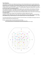
Offsetting Adapter
for the
microTargeting® Drive System
For use with
with Leksell® or Radionics® Stereotactic Frames
Leksell 66-FA-LX-01
Radionics 66-FA-RD-01
User Manual
Copyright© 2001-2002 FHC, Inc. All rights reserved
FHC
FHC Inc., 1201 Main Street, Bowdoin, ME 04287 USA
Phone: 207-666-8190 · US & Canada: 800-326-2905 · Fax: 207-666-8292
E-mail: [email protected] · Website: http://www.fh-co.com
A989-03 Rev C 8/29/06
"Crafted in Maine to be the world's best!"
1
Offsetting Adapter
for the microTargeting Drive System
User Manual A989-03
This User Manual is intended to supplement the User Manual for the microTargeting® Drive
System, A989. The basic instructions for the use of the microTargeting® Drive and its electrode system are documented there and should be read and referred to along with this Manual. Additional information for users of the microTargeting® Drive Accessories (Encoder and
Power Assist with Encoder) is available in User Manual A989-01.
Disclaimer: FHC, Inc. does not accept liability for injury or damage to equipment that may result
from misuse of the microTargeting Drive system or its components.
Tradenames and Trademarks: The names microTargeting® and mT are registered trademarks of
FHC, Inc. All other trademarks and tradenames that appear in this manual are hereby acknowledged.
Copyright Notice: This document and parts thereof must not be reproduced or copied by any
means without the express written consent of FHC, Inc. The contents of this document may not be
used for any unauthorized purpose, and contravention of Copyright will be prosecuted.
CAUTION:
Federal law (USA) restricts this device to sale, distribution, and use by, or on the order of, a
physician.
2
Table of Contents
0 Declarations
0.1 Conditions for use
0.2 Symbols used
1 Operational Manual
1.1 Features, description, and abbreviated procedure
1.2 Operating environment
1. 3 Inventory
1.4 Specifications
2 Reference Manual
2.1 General Information
2.2 Installation and Functional Checkout
2.3 Operational Information
2.3.1 sterilization
2.4 Scheduled Maintenance
3
0.1 - Conditions for use
Intended Use
When used with the microTargeting® Drive System, the Offsetting Adapter adds additional positive functionality to allow
a neurosurgeon to position intracranial microelectrodes, stimulating electrodes, DBSTM electrodes, lesion electrodes or
other instruments more easily and accurately during neurosurgical procedures
Indications For Use
The Offsetting Adapter does not change the Indications For Use of the microTargeting® Drive System:
The microTargeting ® Drive System is intended to be used with commercially available stereotactic systems for
neurosurgical procedures which require the accurate positioning of microelectrodes, stimulation electrodes, or other
instruments in the brain or nervous system.
Warnings
Compatibility
The microTargeting® Offsetting Adapter is specifically designed to be used with the microTargeting® Drive System and
compatible stereotactic frame systems. Use with other components or systems is not authorized and may result in
mechanical failure or injury.
Disassembly
Field disassembly of components beyond the major assemblies as described in this manual may affect calibration and
function. Components requiring repair should be returned to the manufacturer for overhaul or replacement.
Precautions
Storage
Store the mechanical components of the microTargeting Offsetting Adapter at normal room temperatures between –34°
C (-29°F) and 57°C (135°F). Do not expose to temperatures below –34°C (-29°F ) or greater than +70°C (158°F), or a
relative humidity of less than 10% or more than 100%, including condensation, or an atmospheric pressure less than
500 hPa or greater than 1060 hPa for long-term storage.
Component failures
While a high degree of reliability is designed into the system, unexpected failure of components is always possible if
improper storage or handling occurs.
Handling and use
Handle the microTargeting® Offsetting Adapter and its accessories with extreme care. These components may be
damaged if excessive force or incorrect handling occurs.
CAUTION:
Federal law (USA) restricts this device to sale, distribution, and use by, or on the order of, a physician.
0.2 Symbols used on the Labeling, and in this Manual
Information, Caution or Warning:
Warning or caution notices, using the symbol at the left, or bold
type highlighting denote a potential hazard to the health and
safety of users or patients or a need for special attention or care
to be taken. These notices clearly state the nature of the respective hazard and the means by which it can be avoided
4
1.1 Features, Description, Concept and Abbreviated Procedure
Trajectory Positioners and Offsetting Adapter
Offsetting is a unique feature of the mT Drive System available for some stereotactic systems that allows repeatable
parallel track investigation of an area 10 mm in diameter centered on the initial selected trajectory. The Trajectory Positioners are assembled to the provided stereotactic frame system Offsetting Adapter by sliding the long round end of the
Positioner into the Adapter mounting hub, rotating the Positioner until the shoulder engages the recess in the hub, then
pushing the Positioner fully home. The Positioner is then secured by locking it into place with the thumb knob located
on the periphery of the Adapter. The Center Positioner is identified by having only one “tongue” and a rounded surface
opposite it. This rounded surface should be located facing the frame arc when installing the Positioner, or may be rotated 45 degrees either side of this initial position. The Center Positioner will allow nine separate tracks to be investigated (as outlined below ). The Offset Positioner has four tongues. It is installed in the same way, but may be installed
in the hub in any of eight 45 degree positions. Due to frame geometry, a suitable combination of Drive Mount and Positioner location must be used. By assembling the offset positioner to the Drive Mount in one of the available four positions, all of the offsets in the hub may be used without frame interference. (Note: The Drive and electrodes must be
removed to install or rotate the Positioners.) The arrows marked on the tongues of the Offset Positioner indicate the
direction of the 3 mm offset built into the Offset Positioner when installed. Thus 5 x 8 + 9 = 49 parallel track positions
are available in a 10 mm diameter column. This is shown in the figure above and described below. (Note: If it is anticipated that the Offset Positioner will be used, a 14 mm burr hole will be required, and the location of the burr
hole should be carefully determined to allow the full capability of the offsetting feature to be used. )
Center Pattern
3mm Offset
Orthogonal
3mm Offset
Euclidean
Available tracks
14mm Burr Hole
3mm Offset
Postioner
SA8-57-01
Center Positioner
Sa8-56-01
Offsetting Adapter
(Leksell)
Sub24-02
Offsetting Adapter
(Radionics)
SA8-11-01
5
1.2 Operating Environment
The mechanical components of the Offsetting Adapter are designed to be used in the normal operating room
environment, and require no special handling or care exceptional to other mechanical devices used in that
environment. Section 2.3, Operational Information, gives specific instructions on use, care and maintenance.
1.3 Inventory
66-FA-LX-01 Leksell Offsetting Frame Adapter
Sub 24-02 Leksell Offset Adapter
SA8-56-01 mT-DS Center Positioner
SA8-57-01 mT-DS Offset Positioner
66-FA-RD-01 Radionics Offsetting Frame Adapter
SA8-11-01 Radionics Offset Adapter
SA8-56-01 mT-DS Center Positioner
SA8-57-01 mT-DS Offset Positioner
1.4 Specifications
Medical grade stainless steel, hard coat anodized aluminum, and USP Class VI Radel
6
2 Reference Manual
2.1 Reference Information
2.1.1 Shipping/Storage Containers
The corrugated and plastic unit packages used for shipping and storage of these Devices are not
intended to be used during sterilization, but only as a protective case during shipping and receiving.
We recommend saving the containers for future use.
2.1.2 Receiving Inspection
FHC products are factory checked and calibrated but should be carefully inspected before use.
If any exterior damage to the shipping carton is noted, the instrument should be inspected for
obvious physical damage. The contents of each package should be physically checked against the
inventory list in Section 1.4 and the packing list to determine shortages or errors in inventory.
2.1.3 Warranty
All FHC microTargeting® products are unconditionally guaranteed against defects in workmanship for one
year from date of shipment as long as they have been exposed to normal and proper use. Additional
warranty periods are optionally available through service contract. Please contact our Service Department
before attempting any repairs or alterations as any alterations or modifications by other than FHC personnel
will void any guarantee or obligations.
2.1.4 Policies
1. TECHNICAL SUPPORT: It is our policy to provide our customers with the most comprehensive technical
support in the industry. Technical support, including a yearly site visit and telephone or email support , is
provided for the one year warranty period. Additional support, including upgrades, is available after this period
through optional one or three year service contracts. If any questions arise or problems occur, we encourage
you to call or write and we promise to promptly and comprehensively respond to your requirements.
Technical support not covered by warranty or service contract will be charged at an hourly or daily rate, and if
travel is required, this will be at customer expense.
2. TRADE-UP POLICY: It is our policy to offer customers trade-up ability as new and/or expanded capabilities
for their instruments are announced. Please contact our Sales Department for information.
2.1.5 Service/Repairs
Should service be required, please contact our Service Department for return instructions (207-666-8190).
Carefully pack the instrument before returning. All returns must be clean and free of biological
contamination. Use the original packing material or its equivalent to prevent shipping damage. Warranty or
service contract replacement of defective or damaged components will be accomplished by the most
expeditious method available.
Please include a note indicating:
1.
2.
3.
4.
5.
The model number, serial number, and purchase date of the instrument.
The name of the Purchaser
The name and contact information of a person to contact if questions arise.
The "symptoms" indicating that repair is necessary.
A statement that the instrument is being shipped free of any biological contamination
If the instrument is not covered by the warranty or service contract, a quotation will be forwarded to the
sender detailing the repairs necessary and charges, before repair is begun.
7
2.2 Installation and Functional Checkout
Positioners and Offsetting Adapter
Always check the
securing Thumbscrews and knobs
to prevent loosening and movement
of the Drive and
other components.
Attachment to the frame
The Offsetting Adapter and Positioners should be sterilized along with the rest of the mT Drive reusable components.
After sterilization, just prior to surgery, the Offsetting Adapter should be attached to the stereotactic frame, using sterile
assembly procedures. The vertical scale portion of the Leksell Offsetting Adapter will replace the Leksell upper instrument holder, and will be set at the normal zero point. The Radionics Offsetting Adapter is inserted in the frame instrument holder. The Adapters will only attach to the frame in one position, due to their geometry or by aligning the setscrew
attachment position. This ensures that all of the additional components of the system are always installed in the correct
configuration, and that the Drive will be closely aligned with patient anatomy.
2.3 Operational Information
Drive Mount use with Positioners
The mT Drive Mount is the interface between the the microTargeting® Drive and the assembled Trajectory Positioner
and Offsetting Adapter in the frame. It provides a mounting pylon for the Drive and positions it at the correct distance
from the entry point to use standard microTargeting® electrodes. When using the Center Positioner it is normally
mounted so that its rounded front face and tongue profile match the Center Positioner profile (this ensures Drive alignment to the frame or stereotactic system). When using the Offset Positioner, the Drive Mount is normally installed so
that its rounded front surface is facing or no more than 45 degrees from the frame arc, regardless of the position of the
Offset Positioner in the hub. (Note: The Drive Mount can be theoretically be installed in any of four 90 degree positions on the Offset Positioner without changing the possible tracks, however, anatomy or apparatus will make
using the non-standard positions with the rounded face 90 degrees from or in other positions relative to the
frame arc difficult or impossible. All 49 tracks may be accessed using the three standard orientations of the
Drive Mount by using the proper combination of the Offset Positioner and Drive Mount position.) To install the
Drive Mount on the Positioner, slide the Drive Mount over the shorter round protrusion of the Positioner, pushing down
until the Drive mount meets the Positioner flange. A slight rotation may be necessary to align the setscrew location in
the Mount to the Positioner engaging slot. The Mount is then secured to the Positioner using the set screw on its side.
Note: the Drive Mount and Positioner can remain assembled to the Drive when removing it from the Offsetting Adapter
by simply loosening the Hub thumb screw. This allows the Drive to be removed and repositioned very quickly.
8
Track Selection
Track selection of the Drive is accomplished by selecting one of the lettered locations on the hub and orienting the appropriate Positioner to that location. (If a functional targeting formula is used in the planning software based on AC, PC
and mid-plane, and if the stereotactic frame has been carefully positioned, the tracks will be closely aligned with patient
anatomy as shown in conventional atlases). The Center Positioner has a white line on the forward edge of the “tongue”
to indicate which location the Positioner is aligned to. The Offset Positioner is aligned by pointing the four arrows on the
top face of the “tongue” to the appropriate location.
The Center Positioner allows for investigation of nine separate tracks. The selected, or center, trajectory remains constant regardless of orientation. Four parallel tracks at 2mm orthogonal offset are achieved with alignment to locations
A,C,E and G (designated as the black dots below) and four additional 45 degree 2mm Euclidean tracks at locations
B,D,F and H (designated as red). Frame geometry may limit available positions to three, but the other five are redundant
to available positions.
The Offset Positioner can be oriented in any of eight directions yielding an additional forty tracks.
Locations A,C,E and G offset the entire five hole matrix 3mm orthogonal to the origin (orange, green, yellow and blue).
While locations B,D,F and H (purple, gray, olive, turquoise) offset the matrix 3mm in 45 degree locations. All the offsets
are available by using a suitable combination of the four Offset Positioner to Drive Mount possibilities.
The dimensioned grid below can be utilized to determine the precise location of all available track changes. Choose the
position and track closest to the desired grid move
Example: Assuming location A is anterior and location G is lateral.
Q: Select a track that is 3.0mm Anterior and 2.0mm Lateral to the origin.
A: The Lateral most hole of the offset positioner oriented to location A (left most, orange).
9
microTargeting® Drive
To install the microTargeting® Drive to the assembled Positioners and Drive Mount, slide the zeroed Drive
onto and down the pylon until it meets the Drive Mount. Any interference or rough movement could mean
that the securing thumb screws are not backed out far enough. The Drive is secured to the Mount by tightening the securing screws for the pylon and at the front of the Drive foot. Always check to make sure that all
of the assembled components are secured firmly and that they are fully engaged with each other, as
depth accuracy and stability may be affected by incomplete engagement.
Use of the Hub , Positioners, and Drive Mount
Previous sections discuss the assembly and principles behind these components, and should be read to familiarize personnel with their correct assembly.
The Adapter should have been attached to the frame after sterilization prior to surgery.
It is now possible to determine the location of the burr hole by using the Center Positioner and the Verification
Probe. Insert the Verification Probe through the central hole of the Positioner placed in the Adapter and Hub
on the frame. This should touch the skin directly on the trajectory line, and this position can be marked. Make
an incision. A suitable retractor can then be applied. To be exactly sure of burr hole location, mark the skull
by again using the Verification Probe. The burr hole is then made. NOTE: A small pilot hole or indentation helps to facilitate exact positioning of the burr hole. Every effort should be made to prevent slippage or walking of the burr hole device or perforator. This is critical since a mislocated burr hole can
interfere with the trajectory or offset track capability of the mT Drive, requiring enlarging of the opening later.
The Center Positioner, which will be centered on the selected trajectory, can remain fitted to the Hub now, or
it can be optionally removed and fitted to the Drive Mount. This is a matter of user preference, but the assembled Drive Mount and Positioner, with or without the microdrive, are conveniently removed or attached to the
Hub and frame as an assembly.
10
Use of the microTargeting Drive and electrodes with offsetting
Directions for the use of the microTargeting® Drive system are found in the basic User Manual, A989. There
are some minor differences in procedure if offsetting is used and they are included in the below directions.
At this point, the burr hole has been created, and the Drive and electrodes have been preset as necessary
for the target as described in the relevant sections of the basic manual. The Adapter has been attached to
the frame, and the Drive Mount and Center Positioner assembly is in place and secured either in the Drive or
the Adapter and frame. If a Motor Assist or Encoder Drive Accessory is to be used, it will have been attached to the Drive in its sterile sleeve and zeroed as described in User Manual A989-01.
Assemble the microTargeting® Drive, Drive Mount and Center Positioner to the Adapter and frame and secure all locking screws. Test for looseness.
Depending on the insertion tube and electrode system used, assemble the correct components to the Drive
System and insert the insertion tubes and electrodes.
Warning: Never move the insertion tube in the brain unless its stylet or a microelectrode and spacer
or a DBS™ lead is inside it to act as an obturator. Never insert the insertion tube in the Drive without
the carrier in place as it may extend beyond the target area and cause injury .
Record cellular activity as desired until a satisfactory recording is obtained indicating the tip of the microelectrode is at a target region. If the results of the investigation of the central track are unsatisfactory or inconclusive, additional investigations of the 4 remaining tracks in the Matrix are possible without removing the Drive
from the frame as described below.
(Single Electrode System) Remove the IT/electrode combination and use another of the remaining possible
Matrix tracks by reinserting the IT with stylet, then the spacer and microelectrode. There is no need to retract
or move the Drive except as desired to further record along the new track at target depth.
(Array Electrode System) Additional tracks may be investigated without removing the insertion tubes already
in the Matrix, though it may be advisable to temporarily remove the electrode connections to provide working
space. The carrier clamp should be loosened to allow easy insertion of the new IT with its stylet, then retightened after the desired number of additional IT’s are in place. Check all the IT’s before retightening the clamp
to ensure they are bottomed against the clamp. If the Drive has been retracted, return it to a position suitable
to begin recording. Insert the mT electrodes and proceed as before with recording.
If additional investigation of the 4 mm column is desired, the electrodes, tubes and Drive may be removed
and the Center positioner rotated 45 degrees to allow investigation of 4 more tracks.
If investigation of the 9 available tracks in the 4 mm column of the Matrix is inconclusive, the mT Drive system
with offsetting feature allows the offsetting of the Matrix by 3 mm in eight 45 degree increments from the original trajectory. This is done by changing the Center Positioner for the Offset Positioner. (The principles of the
Trajectory Positioners are described above) This change requires that all IT’s and electrodes be removed,
and that the Drive, Drive Mount, and Central Positioner be removed from the hub. The Offset Positioner then
replaces the Central Positioner in the assembly. It is up to the Surgeon, based on his judgment of the results
of the initial recording session, to determine the best direction to offset the Drive and 5 track matrix. The 3
mm offset of the Positioner will allow investigation of tracks up to 5 mm radius from the original central track,
and will additionally access tracks between the initial tracks spaced at 2 mm on center. When in place in the
assembly, the arrows visible on the top surface of the Offset Positioner will indicate the direction of the 3 mm
offset in relation to the original trajectory pattern. Replace the assembled Drive, Drive Mount, and Offset
Positioner in the hub, secure, and proceed as before with recording.
When the target area has been identified, proceed with Lesioning or DBS™ placement.
11
2.3.1 Sterilization
Validated Sterilization Protocols
Steam autoclaving:
minimum temperature, wrapped: 132 ° C
cycle time gravity: 10 min; cycle time prevacuum: 4 min
minimum dry time: 0 min
EtO Gas:
preconditioning:
temperature, wrapped: 54+/- 2 ° C
relative humidity: 40 +/- 20%
vacuum set point: 1.5 psia
steam partial pressure: 2.18psia
preconditioning set point: 2.37psia
preconditioning time: 1 hr
sterilization:
temperature wrapped: 54+/- 2 ° C
relative humidity: 40 +/- 20%
pressure set point: 8.87 psia
EtO concentration: 725 +/- 25 mg/L
gas exposure time: 2 hr
detoxification and drying time: 12 hr
Unwrapped Gravity Steam Sterilization (Flash): to be used only during the surgical procedure in the event components
become contaminated:
temperature set point: 132 ° C
half cycle time: 5 min
minimum dry time: 0 min
Following sterilization, before reassembling the components, use a damp sterile distilled water cloth to wipe off the surfaces
to prevent residue build up.
Users should be aware that the effects of unvalidated sterilization protocols could result in damage to the components
and affect their functioning or performance. The microTargeting® Drive System is not validated for use with alternative
sterilization protocols, and FHC does not recommend or endorse their use. Users with questions regarding this safety
issue should contact FHC’s Technical Service Department at 1-207-666-8190.
2.4 Scheduled Maintenance
The Offsetting Adapter is designed to match the microTargeting® Drive maintenance schedule. It should be inspected
visually prior to each use for physical damage, missing screws or poor fit due to wear or residue buildup. If any component shows wear or damage that could interfere with proper function, please contact the manufacturer for repair or replacement. (See 2.1.5) None of the components require lubrication of any kind.
12