1
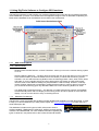
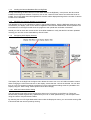
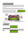
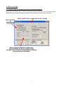
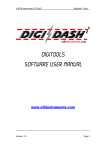
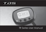
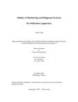
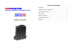
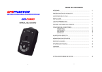
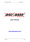
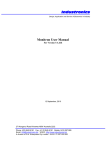
DD2-LITE GPS Upgrade - User Guide
Thank you for purchasing the GPS upgrade option for your DD2-Lite. The GPS system enables two main
functions:
1. Traffic Safety Camera Alert Function
2. GPS based Lap timing function for Track / Test or Race days.
The system also enables the following information to be shown on the LCD display: a) Compass Heading
and Bearing; b) Altitude; c) UTC Satellite Date and Time (you can select either the on-board clock or GPS
data using DigiTools Software) and d) GPS Speed.
Important Note – under the “General” tab in the DigiTools Configure menu, the speed shown on the Display can either be
derived from the hall-effect speed sensor supplied or from the satellite information received by the GPS receiver. If using GPS
to indicate vehicle speed on the DigiDash, please note the following:
a) SPEED SHOWN IS UNADJUSTED AND SHOWS THE ACTUAL TRUE SPEED OF THE VEHICLE
b) SPEED IS ONLY INDICATED WHEN THE RECEIVER HAS A CLEAR VIEW OF THE SKY – PASSING UNDER BRIDGES OR
DRIVING THROUGH TUNNELS WILL INHIBIT THE SATELLITE SIGNAL AND INCUR LOSS OF SPEED INDICATION.
1. Introduction
The DD2-Lite wiring harness incorporates a white 9-way RS232 communication port (DD2 COM Port) on a
flying lead. This is used for communication with the DigiTools software supplied, or for connecting a GPS
Receiver module. This connector can either be directly plugged in to a laptop or via the USB/Serial
Converter cable (if your laptop does not have a 9-pin RS232 port) for initial configuration using the DigiTools
software.
By default, the DD2-Lite is configured with the DD2 COM Port set to communicate with the DigiTools
software using a laptop. This is to enable the user to firstly configure the DigiDash to suit the vehicle
parameters. In order to configure these parameters please refer to the Quickstart Guide and/or User Manual
on the CDROM supplied.
Please note that once the DigiDash has been configured using the DigiTools software the GPS
receiver must be plugged into the white 9-pin connector and the DD2 COM Port Mode set to 1Hz GPS
in order to use the GPS system. Please refer to section 2.1 for more information.
GPS Display Screens
The following instructions assume that you have connected you DD2-Lite to a laptop PC and have already
configured the DD2-Lite to suit your vehicle (speed, rpm, gear ratios, general warning alarm settings etc.).
1
1.1 Using DigiTools Software to Configure GPS functions
The DigiTools software is used to define your preferred settings when using GPS and for keeping the traffic
camera database up to date. The camera tab in the DigiDash Configure menu is dedicated to uploading the
latest camera database file to the DigiDash and for setting user preferences.
1.1.1
GPS Camera Options
1.1.2
Control Config
• “Enable Gatso Camera Detector on Dash” Checkbox - allows you to turn the camera warning system
on or off.
• “Camera Warning Distance” – The drop down box allows the user to set the radius of a circle around
each camera location (in effect the distance from the camera) in metres that the warning system
activates. You can select the warning distance from the following presets: 100m, 200m, 300m, 500m
and 999m. If you are regularly driving in built-up areas with a high density of traffic enforcement
cameras, then a lower distance setting may be preferable to reduce overlap. However, motorway
driving at higher speeds may necessitate to greater distance setting in order to allow more time for
you to react to the warning given. By default the DD2-Lite is set to a warning distance of 300m.
• “On Detect Flip to Warning Screens” – On detection of a traffic enforcement camera, the DigiDash
will automatically switch the LCD display to the warning screen and force Speed on to the red LED
display. You can turn this function off by unchecking this box.
1.1.3
Database File Manager
The DD2-Lite comes pre-loaded with the latest camera database file supplied by Pocket GPS World. In order
to keep your camera database up to date please register with www.pocketgpsworld.com for which there is a
small subscription fee.
This database includes seven types of traffic enforcement camera:
GATSO; MOBILE; TEMPORARY; REDLIGHT; SPECS (average speed);
TRUVELO and MONITRON. For more detailed information regarding the
types of cameras in use please refer to the Pocket GPS World website.
2
1.1.4
Loading the Camera Database File into DigiTools
Having downloading the latest file from Pocket GPS World in the DigiDash (*.cam) format, the file must be
loaded into the DigiTools software. To do this, click on the “Load from Disk” button and select the file to be
loaded. The Pocket GPS World and DigiDash file versions will be displayed along with the number of camera
locations in the database.
1.1.5
Uploading the Camera database to the DD2-Lite
The database must now be uploaded or written to the DigiDash Display. With the DigiDash switched on and
connected to your laptop, clock on the “Write to DigiDash” button and the database file will be uploaded. The
information box in the DigiTools will show the progress of the upload and verification of the data.
Should you wish to check the current version of the DD2 database or verify that the file has been uploaded
correctly you can click on the “Dash Memory Check” button.
1.1.6
Configuring GPS Display Screens
The Display Tab in the DigiTools Configure menu allows the user to turn on or off LCD information screens.
When changing the LCD screens shown on the display, ensure that the “Lite” tab is selected. You can then
turn on or off LCD screens according to preference. Once configured the settings must be uploaded to the
Display using the “Write Config” button (bottom left of above image).
1.1.6.1 AUX Lite Camera Alarm Setting
The AUX warning light LED can be configured to show one of 3 functions on the DD2 Lite. These are:
Neutral Gear (for bike engined cars); Speed Alarm (for over or under speed warning – set the speed value
using the “Alarms” tab) and Camera Alarm.
By selecting the Aux LED Light Mode radio button under the Display tab menu, you can set this warning LED
to illuminate with the camera proximity warning.
3
2. GPS Hardware & DD2 Display Setup
Once configuration of the DigiDash has been completed using the DigiTools software, the GPS receiver
must be plugged into the white 9-pin connector on the DD2-Lite wiring harness.
The system requires that the Garmin GPS Receiver be plugged into the 9-way connector (COM Port) on the
DD2-Lite harness in order to receive signals from the numerous satellites that orbit the Earth. The user must
then change the DD2 Display COM Port mode to 1Hz GPS mode (see 2.2 below).
2.1 Installing the GPS Receiver
The GPS receiver module must be fixed to the vehicle such that it has an unobstructed view of the sky.
The M3 threaded hole on the bottom side of the receiver can be used to fix the module in place, or Velcro
can be used should you wish to easily remove the receiver on a regular basis. The GPS receiver also
encompasses a powerful magnet for fixing to ferrous surfaces.
2.2 Changing the Display COM Port Mode Setting
(Default = DigiTools)
To change the DD2-Lite COM Port Mode from the default DigiTools setting to 1Hz GPS, switch on the DD2Lite and hold down buttons A & B on the Display for 2 seconds to enter the set-up menu screens. By
pressing button A on the display, the DigiDash will cycle through the menu screens on the LCD display. The
COM Port Mode menu screen is the second screen that can be selected and looks like this:
Press button B to edit the COM Port setting and you should see the following LCD display:
Press Button B to cycle through the COM Port Mode options. These options are: DigiTools; GPS 1Hz, GPS
5Hz or SIM GPS. The GPS 1Hz mode should be selected as shown:
Press button A - (Ok) – to enter the setting and hold down buttons A & B together for 2 seconds to exit setup mode. You will be asked if you wish to exit set-up mode – press button A to exit.
Your DD2-Lite is now ready for use with the GPS receiver.
2.3 GPS Status Indication
By switching on ignition and powering up the DigiDash, the system will then begin to acquire the nearest
satellites in order to obtain its position. The GPS related information screens will indicate the status of the
system by showing:
!
?
A
= GPS receiver not connected
= GPS connected but receiver not recognised / communication problem (check DD2 COM Port Mode)
= GPS receiver connected and acquiring satellite positions
4
3. Summary of GPS Information Screens
3.1 Traffic Enforcement Camera Proximity Alert
On switching on ignition and powering up the DigiDash, the GPS receiver will begin scanning the sky to
locate the nearest satellite positions. Note that on powering up for the first time, the receiver module may
take a few minutes to locate and lock on to these satellites and obtain its position. Subsequent warm up
times will be much faster and this period will take only a few seconds unless the vehicle has been left for a
long period of time.
If the traffic camera system has been enabled the DD2 will begin scanning the area for speed and traffic
enforcement cameras. By pressing button A to cycle through the LCD display information screens, the
following screen will indicate the number of cameras within an radius of approximately 1 kilometre.
Should the vehicle enter an area within which a camera is located, the
following LCD information screen will be displayed and speed is
forced onto the red LED display. These screens will be displayed for
the duration that the vehicle remains with the specified area of the
camera. These screens will revert to their original settings upon the vehicle leaving the area. If the AUX
warning light is configured to show camera alarm, this will also illuminate for the same period:
The LCD screen will indicate the type of camera, the distance to the camera in metres, and the speed limit of
the camera’s location.
3.2 Additional GPS information
3.2.1
Latitude and Longitude
This shows the vehicles current location in terms of latitude and longitude:
3.2.2
Speed, Heading and Altitude
The screen shown below provides your compass bearing, compass direction, speed in miles per hour and
altitude in metres above sea level. Please note that the speed indicated is the actual, true speed of the
vehicle.
5
4. GPS Lap Timing
4.1 Configuring DD2-Lite for GPS Lap Timing using DigiTools Software
Please refer to the image below. In order to use the GPS receiver for lap timing, you must ensure that the
DD2 is configured to use it for lap timing purposes, as an alternative to using an infra red system.
6
4.2 Using the GPS Lap Timing System
The GPS lap timing system is very simple to use and it will only take a few minutes for you to familiarise
yourself with using the system for the first time.
4.2.1
Hardware Setup
Included in the GPS package is the manual lap timing button “C” harness. This button should be plugged into
the DD2 “lap trigger” connector on the main harness. Once connected, this button is used to store the GPS
positions of the start line and 3 intermediate splits.
4.2.2
Setting the Start Line / Intermediate Split Time Co-ordinates
The system requires the user to drive round the circuit, pressing the manual button C to store the GPS coordinates to memory:
a) As you cross the start / finish line, press the manual button C and the following screen will be displayed.
The co-ordinates of this location will be stored in memory, and the
next time this position is passed the system begins timing your first
lap.
b) As you drive round the circuit you can divide the lap into 4 sectors. You simply press the button C to set
the GPS location to trigger each split timer:
The DD2 will indicate your performance in relation to previously recorded split times as you lap the circuit.
First the first lap, +9.99s will be shown as there are no previously recorded split times, but your second lap
will indicate whether you as faster or slower than your previous (or best) lap.
c) When the session has finished, you can select the LST / BST screen on the LCD to see your best (BST)
lap time, and by pressing button B on the display, cycle through your recorded laps. These lap times will
be stored indefinitely until you hold down button B for 2 seconds and reset the timers.
d) To begin a new session at a different location, simply repeat the above process to commit the new GPS
locations to memory.
5. Disclaimer
SPEED CAMERA WARNING DATABASE:
ETB Instruments Limited do not guarantee that all fixed or mobile cameras are in the database pre-loaded
on the DigiDash. Therefore we give no representation or warranty as to the accuracy of the content of the
database either expressed or implied and assume no responsibility for errors or omissions. The database is
for informational purposes only. It must be understood that by the ever changing nature the medium, the
database will always have discrepancies. ETB Instruments Limited disclaim all liability in respect of such
information and its provision. ETB Instruments Limited shall not be liable for any loss or damages, speeding
fines or points on your licence suffered as a result of any use of the database, including but not limited to
direct loss or consequential loss.
The Speed Camera Warning Database pre-loaded on the DigiDash system is issued under licence from
PocketGPSWorld.com and is provided on an "as is" and "as available" basis. By using the DigiDash system
which utilises the PocketGPSWorld.com database you agree to be bound by the terms and conditions of the
PocketGPSWorld.com database set out on their website. Please refer to the PocketGPSWorld.com website
for full terms and conditions of use.
7