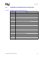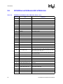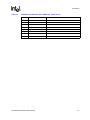
1
SCSI/Ethernet IQ Module
Board Manual
March 1998
Order Number: 272924-003
Information in this document is provided in connection with Intel products. No license, express or implied, by estoppel or otherwise, to any intellectual
property rights is granted by this document. Except as provided in Intel’s Terms and Conditions of Sale for such products, Intel assumes no liability
whatsoever, and Intel disclaims any express or implied warranty, relating to sale and/or use of Intel products including liability or warranties relating to
fitness for a particular purpose, merchantability, or infringement of any patent, copyright or other intellectual property right. Intel products are not
intended for use in medical, life saving, or life sustaining applications.
Intel may make changes to specifications and product descriptions at any time, without notice.
Designers must not rely on the absence or characteristics of any features or instructions marked "reserved" or "undefined." Intel reserves these for
future definition and shall have no responsibility whatsoever for conflicts or incompatibilities arising from future changes to them.
The IQ Module may contain design defects or errors known as errata which may cause the product to deviate from published specifications. Current
characterized errata are available on request.
Contact your local Intel sales office or your distributor to obtain the latest specifications and before placing your product order.
Copies of documents which have an ordering number and are referenced in this document, or other Intel literature may be obtained by calling 1-800548-4725 or by visiting Intel’s website at http://www.intel.com.
Copyright © Intel Corporation, 1998
*Third-party brands and names are the property of their respective owners.
SCSI/Ethernet IQ Module Board Manual
Contents
1
Introduction ................................................................................................................................1-1
1.1
1.2
1.3
1.4
2
Overview................................................................................................................................... 1-1
Features.................................................................................................................................... 1-1
Specifications............................................................................................................................ 1-1
Related Information .................................................................................................................. 1-2
1.4.1 Ordering Information .....................................................................................................1-2
1.4.2 Third-Party Vendor Contact Information .......................................................................1-2
1.4.3 Intel Documentation ......................................................................................................1-2
1.4.4 "Electronic" Information ................................................................................................1-3
1.4.5 Intel Customer Support Contacts..................................................................................1-3
Installation ..................................................................................................................................2-1
2.1
2.2
3
Installation On A Host ............................................................................................................... 2-1
Jumper Configuration ............................................................................................................... 2-1
Hardware Description ............................................................................................................3-1
3.1
3.2
3.3
3.4
3.5
3.6
3.7
3.8
3.9
3.10
3.11
4
4.1
4.2
4.3
4.4
5
5.1
5.2
5.3
5.4
5.5
5.6
Introduction ............................................................................................................................... 3-1
Specifications............................................................................................................................ 3-2
Ethernet Ports........................................................................................................................... 3-2
82557 Ethernet Controller......................................................................................................... 3-2
DP83840 and DP83223 Physical Layer Devices...................................................................... 3-3
Ethernet Port LEDs................................................................................................................... 3-3
Ethernet Port Connectors ......................................................................................................... 3-3
SCSI Ports ................................................................................................................................ 3-3
53C875 SCSI Controller ........................................................................................................... 3-4
SCSI Port Connectors .............................................................................................................. 3-4
SCSI Port Termination .............................................................................................................. 3-4
Programming Information ....................................................................................................4-1
Introduction ............................................................................................................................... 4-1
Ethernet Ports........................................................................................................................... 4-1
Ethernet Address Assignments ................................................................................................ 4-2
SCSI Ports ................................................................................................................................ 4-3
Connectors .................................................................................................................................5-1
SCSI/Ethernet IQ Module Connector........................................................................................ 5-1
Ethernet Port Connectors ......................................................................................................... 5-3
SCSI Port Connectors .............................................................................................................. 5-3
Assembly Drawing .................................................................................................................... 5-4
SCSI/Ethernet IQ Module Board Components ......................................................................... 5-5
SCSI/Ethernet IQ Module Bill of Materials................................................................................ 5-6
SCSI/Ethernet IQ Module Board Manual
iii
Figures
2-1
2-2
3-1
5-1
SCSI/Ethernet IQ Module Installation on Host ..........................................................................2-2
Host (left) and SCSI/Ethernet IQ Module (right) ........................................................................2-3
SCSI/Ethernet IQ Module Block Diagram..................................................................................3-1
SCSI/Ethernet IQ Module Assembly Drawing ...........................................................................5-4
Tables
1-1
1-2
1-3
1-4
3-1
3-2
4-1
5-1
5-2
5-3
5-4
5-5
iv
Related Third-Party Information ................................................................................................1-2
Related Intel Documentation .....................................................................................................1-2
Related Electronic Information ..................................................................................................1-3
Intel Customer Support Telephone Numbers ............................................................................1-3
SCSI/Ethernet IQ Module Interface Signal Assignment ............................................................3-2
SCSI/Ethernet IQ Module Power Requirements .......................................................................3-2
Device Number Assignment ......................................................................................................4-1
SCSI/Ethernet IQ Module Connector Pinout .............................................................................5-1
100BaseTx Connector ...............................................................................................................5-3
SCSI Port Connectors ...............................................................................................................5-3
SCSI/Ethernet IQ Module, Component Description ..................................................................5-5
SCSI/Ethernet IQ Module, Bill of Materials................................................................................5-6
SCSI/Ethernet IQ Module Board Manual
Introduction
1.1
1
Overview
The SCSI/Ethernet IQ Module extends the I/O capabilities of its host board by providing two
Ethernet and two SCSI ports. The SCSI/Ethernet IQ Module connects to the IQ Module Interface
on the host board. The module may be hosted on an Intel IQ80960RP PCI card.
The IQ Module Interface supports up to four PCI devices. The standard signals defined for 32-bit
PCI edge connectors are used for IQ Modules, with some exceptions. See the IQ80960RP
Evaluation Platform User’s Guide for more information on the IQ Module Interface.
1.2
Features
• Two 10/100BaseTx type Ethernet ports, based on Intel’s 82557 Fast Ethernet PCI Bus
Controller, National Semiconductor’s DP83840 Ethernet Physical Layer Device and National
Semiconductor’s DP83228 High Speed Networking Transceiver.
• Two 16-bit Ultra SCSI (40 Mbps) SCSI ports based on the Symbios Logic* SYM53C875
PCI-SCSI I/O Processor with UltraSCSI.
1.3
Specifications
Host Clock Signal:
• 33 MHz Maximum
Physical Characteristics:
• Length x Width x Height: 7.00" x 4.25" x 0.625"
• Occupies only one IQ Module Location
• Occupies only one PCI slot when installed on a PCI host
SCSI/Ethernet IQ Module Board Manual
1-1
Introduction
1.4
Related Information
1.4.1
Ordering Information
When ordering the SCSI/Ethernet IQ Module, refer to the module’s product code name
"IQSCSIFENET".
1.4.2
Third-Party Vendor Contact Information
In addition to the printed technical documentation — the "traditional" collection of product
information — Intel is providing technical (and other) information to you electronically via
FaxBACK, Application Bulletin Board Service (BBS) and Worlwide Web (WWW). The following
subsections identify related technical information, sources for electronic file download, and
technical support.
Table 1-1. Related Third-Party Information
Company
Product
Contact
Symbios Logic
SYM53C875 PCI-SCSI I/O Processor with UltraSCSI
Data Manual
PCI Special Interest Group
PCI Local Bus Specification Revision 2.1
(800) 334-5454
(800) 433-5177 (US)
(503) 693-6232 (Int’l)
(503) 693-8344 (FAX)
National Semiconductor
1.4.3
DP83840 Ethernet Physical Layer Device
DP83223 High Speed Networking Transceiver
(800) 272-9959
Intel Documentation
Documentation is available from you local Intel Sales Representative or Intel Literature Sales.
Intel Corporation
PO Box 5937
Denver, CO 80217-9808
(800) 548-4725
Table 1-2. Related Intel Documentation
Document Title
IQ80960RP Evaluation Platform User’s Guide
1-2
Order #
272913
SCSI/Ethernet IQ Module Board Manual
Introduction
1.4.4
"Electronic" Information
Up-to-date product and technical information is available electronically from these sources.
Table 1-3. Related Electronic Information
Intel’s World-Wide Web (WWW) Location:1
http://www.intel.com/
FaxBACK Service:
US and Canada
Europe
World-Wide
800-628-2283
+44(0)793-496646
916-356-3105
Application Bulletin Board Service:
up to 14.4 Kbaud line, World-Wide
916-356-3600
dedicated 2400 Kbaud line, World-Wide
916-356-7209
Europe
1
1.4.5
+44(0)793-496340
Intel’s presence on the WWW is evolving rapidly; file locations may have changed after this manual was printed. If
you are not finding the desired information, contact Customer Support for assistance.
Intel Customer Support Contacts
Table 1-4. Intel Customer Support Telephone Numbers
Customer Support (US and Canada):
Country
800-628-8686
Literature
Technical Support
Contact Local Distributor
61-2-975-3300
Australia
National
008-257-307
Sydney
Belgium, Netherlands, Luxembourg
61-3-810-2141
010-4071-111
010-4071-111
Canada
800-468-8118
Contact Local Distributor
Finland
358-0-544-644
358-0-544-644
France
33-1-30-57-70-00
33-1-30-57-72-22
Germany
49-89-90992-257
Israel
Hardware: 49-89-903-8529
Software: 49-89-903-2025
972-3-498080
972-3-548-3232
39-02-89200950
39-02-89200950
Contact Local Distributor
0120-1-80387
Sweden
46-8-7340100
46-8-7340100
United States
800-548-4725
800-628-8686
Italy
Japan
SCSI/Ethernet IQ Module Board Manual
1-3
Installation
2.1
Warning:
2
Installation On A Host
Static discharge can severely damage integrated circuits. The host board and SCSI/Ethernet IQ
Module should only be handled with proper static protection. SCSI/Ethernet IQ Modules should
always be installed with power to the host board OFF. Mounting or dismounting a module with the
host power ON could permanently damage the circuitry on the module.
Refer to the SCSI/Ethernet IQ Module’s host board user’s manual for mounting locations.
To install the SCSI/Ethernet IQ Module (Figure 2-1) proceed with the following steps:
1. Remove the corresponding blank mounting bracket from the host board.
a. For PCI hosts, a PCI bracket for the SCSI/Ethernet IQ Module is supplied with the
module. The PCI bracket is mounted to the host board using two small slotted screws, also
supplied.
2. SCSI/Ethernet IQ Modules mount “face down”, that is, with the component side of the module
facing the component side of the host.
a. Hold the module upside down over the host board.
b. Carefully tip the 10/100BaseTx connector of the module through the opening in the host
mounting bracket.
c. Rotate the opposite (120-pin connector) edge of the module downward.
d. Align the module and host connectors.
e. With the module and host aligned, press the two assemblies together, fully mating the
connectors.
3. Secure the mounting hardware, four nylon screws hold the module to spacers on the host.
2.2
Jumper Configuration
There are two jumpers on the SCSI/Ethernet IQ Module, located near the SCSI port connectors.
Each jumper controls active termination for its SCSI port. The default position is ON, where
termination is connected. See Chapter 3 for more information about SCSI port termination. See
Chapter 5 for the location of the termination jumpers.
SCSI/Ethernet IQ Module Board Manual
2-1
Installation
Figure 2-1. SCSI/Ethernet IQ Module Installation on Host
Replacement Mounting Bracket
10/100BaseTx Connector
(angle down and through bracket opening
before mating IQ module connectors)
SCSI/Ethernet IQ Module Board
Mounting Spacers
IQ Module Connectors
Host Board
2-2
SCSI/Ethernet IQ Module Board Manual
SCSI/Ethernet IQ Module Board Manual
i
U25
FW80960RP-33
FFFFFFFF A0
MECHANICAL SAMPLE
[M][C] 1994 ’ 5
I960®
Frequency and
VPP switches
SW1
U3
U4
U1
U2
U5
Flash Memory
IQ Module Connector
1234
Connect this edge connector to your
system’s PCI slot
J3
Emulator Connector
J4
J6
J8
J1
CR3 CR4
J2
DRAM SIMM
Attach SIMMs in connectors at 45° angle
U22
U31
CR1 CR2
User LEDs
(red)
RS-232
Serial Port
Installation
Figure 2-2. Host (left) and SCSI/Ethernet IQ Module (right)
OFF
2-3
3
Hardware Description
3.1
Introduction
This chapter describes the hardware and general operation of the SCSI/Ethernet IQ Module. The
VLSI circuits are not described in detail. The user should consult the manuals and data sheets listed
in Section 1.4, “Related Information” on page 1-2, for a detailed description of these devices.
Connectors are not covered in detail in this chapter, see Chapter 5, “Connectors”, for more
information. Consult Chapter 4 for software and programming information. The SCSI/Ethernet IQ
Module has four PCI devices, two PCI-Ethernet controllers and two PCI-SCSI controllers. The
Ethernet controllers are Intel’s 82557 Fast Ethernet PCI Bus Controller. The SCSI controllers are
Symbios Logic’s SYM53C875 PCI-SCSI I/O Processor with UltraSCSI.
Figure 3-1. SCSI/Ethernet IQ Module Block Diagram
IQ
I/F
Ethernet
Controller
Intel 82557
IQ
I/F
Ethernet
Controller
Intel 82557
IQ Module
Connector
Physical
Ethernet
Isolation
Transformer
MII Layer Device
and
I/F
Transceiver
DP83840
DP83223
Pulse* PE68515
Physical
10/100BaseTx
Connector
Ethernet
Isolation
Transformer
MII Layer Device
I/F
and
Transceiver
DP83840
DP83223
Ethernet
Port A
Pulse PE68515
Ethernet
Port B
10/100BaseTx
Connector
Active Termination
IQ
I/F
SCSI
Port A
Ultra SCSI
Controller
68 Pin SCSI Connector
Symbios 53C875
Active Termination
IQ
I/F
SCSI
Port B
Ultra SCSI
Controller
68 Pin SCSI Connector
Symbios 53C875
A block diagram of the SCSI/Ethernet IQ Module is shown in Figure 3-1. As the block diagram
shows, all four ports are independent.
To support up to four devices on the SCSI/Ethernet IQ Module interface, the host board supplies
four clock, arbitration and interrupt signals to the IQ connector. Additionally, the host board does
not provide IDSEL signals to the SCSI/Ethernet IQ Module interface for PCI configuration cycles.
As shown in Table 3-1, the SCSI/Ethernet IQ Module connects AD16 through AD19 to IDSEL.
The clock, arbitration, and interrupt resources are assigned as shown in Table 3-1.
SCSI/Ethernet IQ Module Board Manual
3-1
Hardware Description
Table 3-1.
SCSI/Ethernet IQ Module Interface Signal Assignment
SCSI/Ethernet IQ
Module Port
E-Net port A
Clocking
Arbitration
CLK-A
REQ0/GNT0
AD16
Interrupt
IRQ-A
E-Net port B
CLK-B
REQ1/GNT1
AD17
IRQ-B
SCSI port A
CLK-C
REQ2/GNT2
AD18
IRQ-C
SCSI port B
CLK-D
REQ3/GNT3
AD19
IRQ-D
3.2
Specifications
Table 3-2.
SCSI/Ethernet IQ Module Power Requirements
Voltage
3.3
IDSEL
Current Typical
Current Maximum
+3.3 V
0A
0A
+5 V
4.05 A
5.11 A
+12 V
0A
0A
-12 V
0A
0A
Ethernet Ports
Both Ethernet ports are 10/100BaseTx type based on Intel’s 82557 Fast Ethernet PCI Bus
Controller, National Semiconductor’s DP83840 Physical Layer Device and National
Semiconductor’s DP83223 High Speed Networking Transceiver.
The 82557 is the core component of the Ethernet interface. It uses a PCI bus interface to
communicate with the host, and a MII (Media Independent Interface) to communicate with a
physical layer device.
3.4
82557 Ethernet Controller
The 82557 contains a 32-bit PCI bus master interface that interacts with the host memory to access
data for transmission or deposit received data.
The 82557 has large transmit and receive FIFOs that are unidirectional and independent of each
other. The FIFOs provide temporary storage area for frames as they are received or transmitted.
The FIFOs allow the 82557 to withstand long PCI latencies without losing incoming data or
corrupting outgoing data.
The interface on the 82557 for FLASH support is not used on the SCSI/Ethernet IQ Module. The
EEPROM interface has a serial EEPROM attached and is used to store the port’s Ethernet address.
3-2
SCSI/Ethernet IQ Module Board Manual
Hardware Description
3.5
DP83840 and DP83223 Physical Layer Devices
The National Semiconductor DP83840 and DP83223 provide the physical layer interface function
for a 100BaseTx or 10BaseT Ethernet network.
The host side of the DP83840 connects to the Ethernet controller using the IEEE MII (Media
Independent Interface). The DP83840 does not have a separate host interface; internal registers are
accessed using the MII. The 100Mbps line side of the DP83840 connects to the DP83223 which in
turn connects to the Ethernet isolation transformer. The 10Mbps line side of the DP83840 connects
directly to the Ethernet isolation transformer.
When receiving, the DP83840 and DP83223 physical layer pair recover data and clock from the
incoming signals. The recovered data stream is then decoded and output to the Ethernet controller
through the MII. When transmitting, the physical layer pair receive binary data from the MII, then
encode and transmit that data to the network.
The SCSI/Ethernet IQ Module configures the DP83840 to perform auto-negotiation per IEEE
802.3u. Auto-negotiation ensures that the highest performance protocol will be selected based on
the ability of the SCSI/Ethernet IQ Module link partner.
3.6
Ethernet Port LEDs
Each Ethernet port on the SCSI/Ethernet IQ Module has four LEDs driven by the DP83840 that
provide a visual indication of network status:
• The LED labeled “LNK” indicates link status.
• The LED labeled "ACT" indicates network activity. The "ACT" LED blinks when there is
transmit or receive activity.
• The LED labeled "100" is on continuously when the port is connected to a 100 Mbps network.
• The LED labeled "FDX" indicates full duplex mode status. The LED is on continuously when
in full duplex mode.
3.7
Ethernet Port Connectors
The Ethernet ports on the SCSI/Ethernet IQ Module connect to a dual, shielded RJ45 (modular
phone type) connector that conforms to the 10/100BaseTx specification. The connector pin-out can
be found in Chapter 5. The Ethernet ports are indicated on the SCSI/Ethernet IQ Modules front
panel and on the assembly drawing in Chapter 5.
3.8
SCSI Ports
Both SCSI ports are single-ended 16-bit UltraSCSI (40 Mbps) SCSI ports based on the Symbios
Logic SYM53C875 PCI-SCSI I/O Processor with UltraSCSI. The 53C875 is the core component
of the SCSI interface. It uses a PCI interface to communicate with the host and connects directly to
the SCSI bus.
SCSI/Ethernet IQ Module Board Manual
3-3
Hardware Description
3.9
53C875 SCSI Controller
The 53C875 is an intelligent SCSI host adapter which includes a high performance SCSI core, a
32-bit PCI bus master DMA core and an integrated SCSI SCRIPTS processor.
The SCSI core supports the 8- or 16-bit data bus. It supports UltraSCSI synchronous transfer rates
up to 40 Mbps, SCSI-2 synchronous transfer rates up to 20 Mbps and asynchronous transfer rates
up to 10 Mbps on a 16-bit SCSI bus.
The 32-bit PCI bus master DMA core is tightly coupled to the SCSI core through the SCRIPTS
processor, which supports uninterrupted scatter/gather memory operations. A 536 byte FIFO
allows the 53C875 to support up to 128 longword bursts across the PCI interface.
The SCRIPTS processor executes complex SCSI bus sequences independently of the host CPU.
Algorithms written in SCSI SCRIPTS control the actions of the SCSI and DMA cores and are
executed from the host boards RAM.
3.10
SCSI Port Connectors
Each SCSI port connects to a 68-pin high density D-type connector on the top edge of the
SCSI/Ethernet IQ Module PCB. These connectors conform to the "non-shielded connector" of the
SCSI-2 and UltraSCSI extension of the SCSI-3 specification. The pin-out of these connectors
conforms to the "connector contact assignments for the single ended primary bus" of the SCSI-2
and UltraSCSI extension of the SCSI-3 specification. The SCSI port connector pin-outs can be
found in Chapter 5.
3.11
SCSI Port Termination
The SCSI specification calls for all signals not defined as RESERVED, GROUND or TERMPWR
to be terminated at each end of the cable. Additionally, the UltraSCSI extension of the SCSI-3
specification requires active termination in single ended UltraSCSI systems. The SCSI/Ethernet IQ
Module uses an integrated active terminator device that has reduced line capacitance for operation
at UltraSCSI transfer rates.
If the SCSI/Ethernet IQ Module SCSI port is not at either end of the SCSI cable, then the
termination must be disconnected. A two position jumper near each SCSI port connector is used to
disconnect or turn off the active termination. The jumper shunt in the ON position connects the
termination and the jumper shunt in the OFF position disconnects the termination.
3-4
SCSI/Ethernet IQ Module Board Manual
4
Programming Information
4.1
Introduction
This chapter provides software and programming information for the SCSI/Ethernet IQ Module.
This chapter does not contain a complete list of all registers in all devices. The user should consult
the manuals and data sheets listed in Section 1.4, “Related Information” on page 1-2, for a detailed
description of registers and configuration information. See Chapter 3 for hardware and general
operation of the SCSI/Ethernet IQ Module.
The SCSI/Ethernet IQ Module connects to the IQ Module Interface of its host board. The IQ
Module Interface is a 32-bit PCI bus conforming to the PCI Local Bus Specification Revision 2.1,
with exceptions noted in the host board users manual and Chapter 3.
For PCI Type 0 configuration cycles, the device number assignment is as shown in Table 4-1.
Table 4-1.
Device Number Assignment
SCSI/Ethernet IQ Module Port
4.2
IDSEL
Device
E-NET Port A
AD16
Number 5
E-NET Port B
AD17
Number 6
E-NET Port C
AD18
Number 7
E-NET Port D
AD19
Number 8
Ethernet Ports
The 82557 establishes a shared memory communication system with the host CPU. This shared
memory is divided into three parts: the Control/Status Registers (CSR), the Command Block List
(CBL) and the Receive Frame Area (RFA). The CSR resides on-chip and can be accessed by either
I/O or memory cycles, while the rest of the 82557 memory structures reside in system (host)
memory. The first 8 bytes of the CSR is called the System Control Block (SCB). The SCB serves
as a central communication point for exchanging control and status information between the host
CPU and the 82557.
The host software controls the state of the 82557 Command Unit (CU) and Receive Unit (RU) (for
example Active, Suspended, Idle) by writing commands to the SCB. The 82557 posts the status of
the CU and RU in the SCB Status word and indicates status changes with an interrupt. The SCB
also holds pointers to a linked list of action commands called the CBL and a linked list of received
resources called the RFA.
Parameters which must be established prior to making the 82557 operational included internal
configuration values (established using the Configure Command) and assigning an individual
Ethernet address (using the Individual Address Setup Command). Note that the aforementioned
shared memory communication architecture must be established prior to the execution of 82557
action commands. Refer to the 82557 manual for further information regarding device
configuration.
SCSI/Ethernet IQ Module Board Manual
4-1
Programming Information
4.3
Ethernet Address Assignments
The ethernet address is pre-programmed at the factory and is stored in the on-board serial
EEPROM. The following describes the ethernet address assignment.
To provide a unique ethernet address for all IQ modules with Ethernet ports, an algorithm has been
established that combines the IQ module number, the port number and the board’s serial number.
The Ethernet address is a six byte number. The first three bytes are assigned to Cyclone
Microsystems and are fixed at:
$ 00 80 4D
The last three bytes are broken into three binary fields:
b XXXX XXXX YYZZ ZZZZ ZZZZ ZZZZ
The first binary field, XXXX XXXX is the Module ID, in Hex. The SCSI/Ethernet IQ Module ID
is 73 converted ($49).
The second binary field, YY is the port number. For the SCSI/Ethernet IQ Module there are two
ethernet ports:
E-Net Port A, YY = 00
E-Net Port B, YY = 01
The third binary field, ZZ ZZZZ ZZZZ ZZZZ is the modules serial number converted to hex. For
example, if the module serial number is 1234 then:
1234d = $4D2
ZZ ZZZZ ZZZZ ZZZZ = 00 0100 1101 0010
The complete ethernet address for an SCSI/Ethernet IQ Module with serial number 1234 would be:
E-Net Port A = $ 00 80 4D 44 04 D2
E-Net Port B = $ 00 80 4D 49 44 D2
4-2
SCSI/Ethernet IQ Module Board Manual
Programming Information
4.4
SCSI Ports
This section defines specific setup requirements for the SYM53C875 processors to ensure proper
operation of the SCSI/Ethernet IQ Module. To use Ultra SCSI capabilities of the SYM53C875, it is
necessary to enable the clock doubler. This involves properly configuring registers STEST1
(register 4DH), STEST3 (register 4FH), and SCNTL1 (register 01H) of the SYM53C875. See the
SYM53C875 PCI-SCSI I/O Processor with UltraSCSI Data Manual for further information.
The default operating mode for the SCSI ports is 8-bit, 10 Mbps transfer rate. The SYM53C875
supports both wide-SCSI (16-bit) and Ultra SCSI, resulting in a maximum potential transfer rate of
40 Mbps (16-bit). Operation in wide and/or Ultra SCSI modes requires negotiation with the
initiator or target. See the SCSI specification for the SCSI message system definition.
The Synchronous Clock Conversion Factor bits SCF2, SCF1, and SCF0 (bits[6:4]) of SCSI
Control Three Register (SCNTL3, register 03H) should be set to match the data transfer period
negotiated with the target. For transfer periods of 100 ns or greater, set to 0,1,1 to divide the SCLK
frequency of 80 MHz by 2 (for a 40 MHz clock input internally to the SYM53875). For transfer
periods of less than 100 ns, set these bits to 0,0,1 to divide SCLK by 1. Set the Clock Conversion
Factor bits CCF2, CCF1, and CCF0 (bits[2:0]) to 1,0,1.
Note:
The SCSI/Ethernet IQ Module uses a 40 MHz external SCLK which is doubled by the
SYM53C875 to support UltraSCSI functions.
Host bus parity checking should not be used. The MPEE bit (bit 3) of the Chip Test Four (CTEST4,
register 21H) should be left at its default value of 0.
The SCSI Differential Mode bit DIF (bit 5) of the SCSI Test Register 2 (STEST2, register 4EH)
should be left at its default value of zero. The SCSI/Ethernet IQ Module uses the single-ended
transceiver pins of the SYM53C875.
SCSI/Ethernet IQ Module Board Manual
4-3
5
Connectors
5.1
SCSI/Ethernet IQ Module Connector
IQ Modules use an AMP Champ 0.050" FH board-to-board connector with 120 pins. AMP plug
P/N 176380-4 is located on the host platform and attaches to receptacle AMP P/N 176372-5. This
connector combination allows for a 12 mm (0.472") board-to-board spacing.
Table 5-1.
SCSI/Ethernet IQ Module Connector Pinout
Pin
Signal
Pin
Signal
1
S_TRST
61
-12 V
2
+12 V
62
S_TCK
3
S_TMS
63
GND
4
S_TDI
64
N/C
5
+5 V
65
+5 V
6
S_INTA
66
+5 V
7
S_INTC
67
S_INTB
8
+5 V
68
S_INTD
9
CLK_C
69
S-REQ3
10
+5 V
70
S_REQ1
11
CLK_D
71
S_GNT3
12
GND
72
GND
13
GND
73
GND
14
S_GNT1
74
CLKA
15
S_RST
75
GND
16
+5 V
76
CLKB
17
S_GNT0
77
GND
18
GND
78
S_REQ0
19
S_REQ2
79
+5 V
20
S_AD30
80
S_AD31
21
3.3 V (1)
81
S_AD29
22
S_AD28
82
GND
23
S_AD26
83
S_AD27
24
GND
84
S_AD25
25
S_AD24
85
3.3 V (1)
26
S_GNT2
86
S_C/BE3
27
3.3 V (1)
87
S_AD23
28
S_AD22
88
GND
SCSI/Ethernet IQ Module Board Manual
5-1
Connectors
Table 5-1.
SCSI/Ethernet IQ Module Connector Pinout (Continued)
Pin
Pin
Signal
29
S_AD20
89
S_AD21
30
GND
90
S_AD19
31
S_AD18
91
3.3 V (1)
32
S_AD16
92
S_AD17
33
3.3 V (1)
93
S_C/BE2
34
S_FRAME
94
GND
35
GND
95
S_IRDY
36
S_TRDY
96
3.3 V (1)
37
GND
97
S_DEVSEL
38
S_STOP
98
GND
39
3.3 V (1)
99
S_LOCK
40
N/C
100
S_PERR
41
N/C
101
3.3 V (1)
42
GND
102
S_SERR
43
S_PAR
103
3.3 V (1)
44
S_AD15
104
S_C/BE1
45
3.3 V (1)
105
S_AD14
46
S_AD13
106
GND
47
S_AD11
107
S_AD12
48
GND
108
S_AD10
49
S_AD9
109
GND
50
S_C/BE0
110
S_AD8
51
3.3 V (1)
111
S_AD7
52
S_AD6
112
3.3 V (1)
53
S_AD4
113
S_AD5
54
GND
114
S_AD3
55
S_AD2
115
GND
56
S_AD0
116
S_AD1
57
+5 V
117
+5 V
58
N/C
118
N/C
59
+5 V
119
+5 V
60
+5 V
120
+5 V
1.
5-2
Signal
3.3 V pins are decoupled to ground with 0.01 µF capacitors to provide AC return paths.
SCSI/Ethernet IQ Module Board Manual
Connectors
5.2
Ethernet Port Connectors
The Ethernet ports on the SCSI/Ethernet IQ Module connect to a dual, shielded RJ45 (modular
phone type) connector that conforms to the 10/100BaseTx specification.The pinout for each
Ethernet port is shown in Table 5-2.
Table 5-2.
100BaseTx Connector
Pin
Signal
Description
1
TX+
Output
2
TX-
Output
3
RX+
Input
4
Not Used
5
Not Used
6
5.3
RX-
Input
7
Not Used
8
Not Used
SCSI Port Connectors
Each SCSI port connects to a 68-pin high-density D-type connector on the top edge of the
SCSI/Ethernet IQ Module. These connectors conform to the "non-shielded connector" of the
SCSI-2 and UltraSCSI extension of the SCSI-3 specification. These connectors pinouts conform to
the "connector contact assignments for the single ended primary bus" of the SCSI-2 and UltraSCSI
extension of the SCSI-3 specification. The SCSI port connector pinout is shown in Table 5-3.
Table 5-3.
SCSI Port Connectors
Pin
Signal
Pin
Signal
Pin
Signal
Pin
Signal
1
Ground
35
-DB12
18
TERMPWR
52
TERMPWR
2
Ground
36
-DB13
19
N/C
53
N/C
3
Ground
37
-DB14
20
Ground
54
Ground
4
Ground
38
-DB15
21
Ground
55
-ATN
5
Ground
39
-DBP1
22
Ground
56
Ground
6
Ground
40
-DB0
23
Ground
57
-BSY
7
Ground
41
-DB1
24
Ground
58
-ACK
8
Ground
42
-DB2
25
Ground
59
-RST
9
Ground
43
-DB3
26
Ground
60
-MSG
10
Ground
44
-DB4
27
Ground
61
-SEL
11
Ground
45
-DB5
28
Ground
62
-C/D
12
Ground
46
-DB6
29
Ground
63
-REQ
13
Ground
47
-DB7
30
Ground
64
-I/O
14
Ground
48
-DBP0
31
Ground
65
-DB8
15
Ground
49
Ground
32
Ground
66
-DB9
16
Ground
50
Ground
33
Ground
67
-DB10
17
TERMPWR
51
TERMPWR
34
Ground
68
-DB11
SCSI/Ethernet IQ Module Board Manual
5-3
Connectors
5.4
Assembly Drawing
The layout or assembly drawing is shown in Figure 5-1. This figure can be used to identify
Ethernet Ports A & B and SCSI Ports A & B. This figure also shows the location of the SCSI
terminator jumpers.
Q1
Q4
Q3
CR1
CR2 TP1 TP2
C8
U6
+
R11 R12
U7
L1
L2
C7
ETHERNET
PORT B
+
R10
C6
U2
C5
R8 R5
U8
J1
U1
R7
U5
C4
ETHERNET
PORT A
R2 R3
U4
C3
R4 Q2
R9 R6
U13
C1
R1
C2
Figure 5-1. SCSI/Ethernet IQ Module Assembly Drawing
+
J2
SCSI PORT B
TERMINATION CONTROL
FOR SCSI PORT B
5-4
+
U13
C14
R19
U17
F2
R22
U16
CR5
CR6
U15
R20 C11
C16
R23
U12
U18
J3
Z2
Z1
0307B
ASSEMBLY TOP
270-0370-02
IQ70
C6
F1
Q8
U4
J4
U5
R9 R6
C12
Q7
C15
U14
Q6
R21
R14
Q5
R8 R5
TP4
R13
TP3
C10
CR3
CR4
C9
U9
SCSI PORT A
TERMINATION CONTROL
FOR SCSI PORT A
SCSI/Ethernet IQ Module Board Manual
Connectors
5.5
SCSI/Ethernet IQ Module Board Components
Table 5-4.
SCSI/Ethernet IQ Module, Component Description
Component
Function
J1
10/100BaseTx, Dual-modular connector, Ethernet A & B
J2
68-pin Connector, SCSI Port B
J3
68-pin Connector, SCSI Port A
J4
120-pin Connector, IQ Module Interface
U1
Microchip* 93C46, Serial EEPROM
U2
Microchip 93C46, Serial EEPROM
U3
Kyocera* HC-1-TSE 50 MHz, TTL Oscillator
U4
National Semiconductor, DP83223, Transceiver
U5
National Semiconductor, DP83840, Physical Layer Device
U6
Intel 82557, Ethernet Controller
U7
Intel 82557, Ethernet Controller
U8
Pulse Engineering, PE-68515, Isolation Transformer
U9
Pulse Engineering, PE-68515, Isolation Transformer
U10
National Semiconductor, DP83223, Transceiver
U11
National Semiconductor, DP83840, Physical Layer Device
U12
Symbios Logic, 53C875, UltraSCSI Controller
U13
Symbios Logic, 53C875, UltraSCSI Controller
U14
Kyocera* HC-1-TSE 40 MHz, TTL Oscillator
U15
Unitrode, UCC5618, UltraSCSI Terminator
U16
Unitrode, UCC5618, UltraSCSI Terminator
U17
Unitrode, UCC5618, UltraSCSI Terminator
U18
Unitrode, UCC5618, UltraSCSI Terminator
Z1
Terminator Jumper, SCSI Port A
Z2
Terminator Jumper, SCSI Port B
SCSI/Ethernet IQ Module Board Manual
5-5
Connectors
5.6
SCSI/Ethernet IQ Module Bill of Materials
Table 5-5.
SCSI/Ethernet IQ Module, Bill of Materials (Sheet 1 of 2)
Quantity
5-6
Part
Reference
2
93C46
U1, U2
1
OSC50 MHz
U3
2
DP83223A
U4, U10
2
DP83840
U5, U11
2
82557
U6, U7
2
PE-68515
U8, U9
2
53C875
U12, U13
1
OSC40 MHz
U14
4
UCC5618
U15, U16, U17, U18
2
SMT_BEAD, 2743019447
L1, L2
10
BEAD_1206, BLM31A02PT
L3, L4, L5, L6, L7, L8, L9, L10, L11, L12
2
1N4001
CR5, CR6
8
CMPT4401
Q1, Q2, Q3, Q4, Q5, Q6, Q7, Q8
1
CONN8TJ-SHL2
J1
2
CONN68
J2, J3
1
CONN_IQ_PCI
J4
2
FUSE2A
F1, F2
2
JUMP3X1
Z1, Z2
2
LED2HIGH
CR1, CR2, CR3, CR4
29
CAP, C, 1206, 0.1 µF
C1, C8, C10, C15, C16, C17, C18, C19, C20, C21, C22, C28,
C29, C30, C34, C35, C37, C38, C40, C42, C46, C47, C52,
C53, C54, C55, C57, C58, C67
16
CAP, C, 1206, 0.01 µF
C2, C3, C4, C6, C9, C13, C23, C26, C33, C36, C39, C41,
C43, C45, C51, C56
4
CAP, C, 1206, 10 pF
C24, C25, C49, C50
4
CAP, C, 1206, 1000 pF
C12, C31, C32, C48
10
CAP, T, 3528, 6.8 µF
C27, C44, C59, C60, C61, C62, C63, C64, C65, C66
2
CAP, T, 7343, 22 µF
C5, C11
2
CAP, T, 7343, 33 µF
C7 C14
2
R, 1/8W, 1206, 3.3 Kohm, 5%
R39, R40
4
R, 1/8W, 1206, 10 Kohm, 5%
R1, R22, R23, R24
16
R, 1/8W, 1206, 10 ohm, 5%
R14, R31, R34, R41, R48, R51, R52, R53, R54, R67, R68,
R69, R78, R79, R80, R82
3
R, 1/8W, 1206, 22 ohm, 5%
R25, R26, R83
4
R, 1/8W, 1206, 39 ohm, 5%
R13, R32, R33, R81
6
R, 1/8W, 1206, 47 ohm, 5%
R35, R36, R37, R85, R86, R87
SCSI/Ethernet IQ Module Board Manual
Connectors
Table 5-5.
SCSI/Ethernet IQ Module, Bill of Materials (Sheet 2 of 2)
Quantity
Part
Reference
8
R, 1/8W, 1206, 75 ohm, 5%
R55, R56, R57, R58, R63, R64, R65, R66
8
R, 1/8W, 1206, 000 ohm, 5%
R42, R43, R49, R50, R70, R71, R76, R77
12
R, 1/8W, 1206, 120 ohm, 5%
R5, R6, R15, R16, R44, R45, R46, R47, R59, R62, R73, R74
12
R, 1/8W, 1206, 200 ohm, 5%
R8, R9, R17, R18, R27, R28, R29, R30, R60, R61, R72, R75
2
R, 1/8W, 1206, 510 ohm, 5%
R38, R84
4
RNC4R8P, 4.7 Kohm, 5%
R2, R10, R11, R19
4
RNC4R8P, 10 Kohm, 5%
R3, R7, R12, R20
2
RNC4R8P, 470 ohm, 5%
R4, R21
SCSI/Ethernet IQ Module Board Manual
5-7