1
MON960
Debug Monitor
User’s Guide
Order Number: 484290-006
Revision
Revision History
Date
-001
Original Issue.
01/93
-002
Updated for V1.1 release.
02/93
-003
Revised for MON960 release 2.0.
05/94
-004
Revised for MON960 release 2.1.
11/94
-005
Revised for MON960 release 3.0.
12/95
-006
Revised for MON960 release 3.1.
01/97
In the United States, additional copies of this manual or other Intel literature may be obtained by writing:
Literature Distribution Center
Intel Corporation
P.O. Box 7641
Mt. Prospect, IL 60056-7641
Or you can call the following toll-free number:
1-800-548-4725
In locations outside the United States, obtain additional copies of Intel documentation by contacting your local Intel sales
office.
Intel Corporation makes no warranty of any kind with regard to this material, including, but not limited to, the implied
warranties of merchantability and fitness for a particular purpose. Intel Corporation assumes no responsibility for any errors
that may appear in this document. Intel Corporation makes no commitment to update nor to keep current the information
contained in this document.
Intel Corporation assumes no responsibility for the use of any circuitry other than circuitry embodied in an Intel product.
No other circuit patent licenses are implied.
Intel software products are copyrighted by and shall remain the property of Intel Corporation. Use, duplication or disclosure
is subject to restrictions stated in Intel’s Software License Agreement, or in the case of software delivered to the government,
in accordance with the software license agreement as defined in FAR 52.227-7013.
No part of this document may be copied or reproduced in any form or by any means without prior written consent of Intel
Corporation.
Intel Corporation retains the right to make changes to these specifications at any time, without notice.
Contact your local sales office to obtain the latest specifications before placing your order.
*
Other brands and names are the property of their respective owners.
printed on
recycled paper
Copyright 1993-1995, 1997. Intel Corporation. All rights reserved.
Contents
Preface
Purpose..............................................................................ix
Audience ............................................................................ix
Notational Conventions ......................................................ix
Contents.............................................................................xi
Customer Service...............................................................xiii
Related Publications ..........................................................xiii
Chapter 1 Getting Started
Host System Requirements................................................1-1
Preparing for Installation on UNIX......................................1-2
Installing on UNIX Hosts ....................................................1-2
Preparing for Installation in Windows .................................1-4
Installing on Windows Hosts ..............................................1-4
What’s Next?......................................................................1-4
Chapter 2 Overview
Product Summary ..............................................................2-1
Monitor Features ...........................................................2-2
Components of the Monitor ...........................................2-2
Downloading ......................................................................2-5
Serial Download ............................................................2-6
Parallel Download..........................................................2-6
PCI Download ...............................................................2-7
Board Configurations .........................................................2-7
MONDB TCP/IP Communications Support ........................2-8
ApLink Support ..................................................................2-9
iii
MON960 Debug Monitor User's Guide
Chapter 3 Using the Monitor
Purpose..............................................................................3-1
Connecting to the User Interface........................................3-1
Setting Breakpoints ............................................................3-2
Displaying Memory.............................................................3-3
Trace Events ......................................................................3-4
Loading MON960 Into Flash ..............................................3-5
Downloading MON960 to an Evaluation Platform..........3-6
PCI80960DP Evaluation Platform..................................3-6
IQ80960RP Evaluation Platform....................................3-9
Chapter 4 Monitor Commands
Elements of the Command Language................................4-1
Names ...........................................................................4-1
Addresses......................................................................4-1
Numbers ........................................................................4-2
Overview of Commands .....................................................4-2
Alphabetical Command Reference.....................................4-5
Chapter 5 Retargeting the Monitor
Types of Source Files.........................................................5-1
Code Areas Affected by Retargeting..................................5-2
Modifying Board-specific Files............................................5-3
Board-specific Files ............................................................5-4
board.h ..........................................................................5-4
board_hw.c ....................................................................5-5
Memory Configuration ...................................................5-11
Creating the ROM Image ...................................................5-15
Edit the Makefile ............................................................5-16
Copy the Linker-directives File.......................................5-17
Configure the Makefile...................................................5-17
Make the Monitor Files Using a Make Utility ..................5-22
iv
Contents
Produce New EPROMs .................................................5-23
Install the New EPROMs ...............................................5-23
Debugging the Monitor.......................................................5-24
Verifying Monitor Operation...........................................5-24
Troubleshooting Host-target Serial Communication
Problems .....................................................................5-25
PCI Retargeting .................................................................5-27
Board Initialization..............................................................5-28
Routines in leds_sw.c ........................................................5-29
Serial Device Driver Routines ............................................5-35
Routines in 82510.c and 16552.c ......................................5-37
Routines in flash.c..............................................................5-38
Local Routines in flash.c................................................5-42
Routines in paradrvr.c ........................................................5-43
Parallel Download Example Code .................................5-44
Chapter 6 Theory of Operation
System Initialization ...........................................................6-1
Faults .................................................................................6-5
Stacks ................................................................................6-6
Program Execution.............................................................6-8
System Calls ......................................................................6-9
High Speed Downloading...................................................6-12
Parallel Download..........................................................6-12
PCI Download ...............................................................6-14
Monitor Core Source ..........................................................6-16
Variables .......................................................................6-16
Routines ........................................................................6-17
User Interface Source ........................................................6-20
Host Interface Source ........................................................6-21
Host-target Communications System .................................6-21
Serial Device Driver .......................................................6-22
v
MON960 Debug Monitor User's Guide
Communications Packet Structure.................................6-22
Serial Autobaud .............................................................6-24
MON960 Support for PCI Communication .........................6-24
Chapter 7 The MON960 Application Environment
Purpose..............................................................................7-1
Execution Environment ......................................................7-1
System Procedure Table ...............................................7-1
Fault Table.....................................................................7-2
Interrupt Table ...............................................................7-2
Control Table .................................................................7-2
Monitor Stacks...............................................................7-3
Changing the Environment ............................................7-3
Libraries .............................................................................7-8
libll .................................................................................7-8
libmon ............................................................................7-9
Compiling an Application Program .....................................7-12
Interrupts ............................................................................7-13
Debugging Interrupt Routines ............................................7-14
Faults and Interrupts While Executing................................7-16
i960 Processor Cache Invalidation by MON960.................7-16
System Calls ......................................................................7-17
Reserved Registers............................................................7-18
Linking the Monitor with an Application ..............................7-22
Chapter 8 Host Debugger Interface (HDI)
Purpose..............................................................................8-1
Types and Variables ..........................................................8-3
Imported Routines..............................................................8-10
Host Debugger Interface Library Routines (HDIL)..............8-12
HDIL Support for PCI Communication................................8-48
vi
Contents
Appendix A
Target Board Notes
Cyclone Evaluation Boards ................................................A-1
PCI80960DP Evaluation Boards ...................................A-1
IQ80960RP Evaluation Boards......................................A-2
Appendix B
MONDB Execution Utility
TCP/IP Communication......................................................B-2
Hardware Requirements................................................B-3
Software Requirements .................................................B-3
Server Semantics ..........................................................B-3
Client Semantics............................................................B-4
PCI Communication ...........................................................B-4
Hardware Requirements................................................B-4
Software Requirements — PCI Driver Installation .........B-5
Mechanics .....................................................................B-5
Semantics......................................................................B-6
Example ........................................................................B-6
Serial communication.........................................................B-6
Hardware Requirements................................................B-6
Windows PCI Download.....................................................B-7
Hardware Requirements................................................B-7
Mechanics .....................................................................B-7
Windows Parallel Download...............................................B-8
Hardware Requirements................................................B-8
Mechanics .....................................................................B-8
UNIX Parallel Download ................................................B-9
Hardware Requirements................................................B-10
Mechanics .....................................................................B-10
Selecting the Parallel Port On Your UNIX Host .............B-10
Default Serial and Parallel Port Devices ............................B-12
vii
MON960 Debug Monitor User's Guide
Invocation Syntax...............................................................B-13
TCP/IP Options..............................................................B-13
PCI Options ...................................................................B-14
Parallel Download Options ............................................B-15
Communication Protocol Options ..................................B-16
Serial Communication Options ......................................B-17
MONDB Commands...........................................................B-19
Examples of Using MONDB ...............................................B-21
Windows PCI Downloading ...........................................B-21
UNIX Parallel Downloading (SPARCstation 5) ..............B-21
Communicating from UNIX Hosts at 57600 or
115200 Baud ...............................................................B-22
Index
Figures
2-1
2-2
5-1
5-2
6-1
6-2
MON960 Structure.....................................................2-3
TCP/IP Server/Workstation Communication..............2-8
Memory Map for Cyclone i960 Sx/Kx/Cx/Jx/Hx
Boards .....................................................................5-14
Memory Map for IQ80960RP Cyclone Boards...........5-15
Stack Switch..............................................................6-7
MON960 System Call Sequence ...............................6-10
4-1
4-2
4-3
4-4
5-1
5-2
5-3
5-4
Execution and Break Commands ..............................4-3
Memory Access Commands......................................4-4
Monitor Environment Commands ..............................4-5
ApLink Support Commands.......................................4-5
List of Board Names and Abbreviations ....................5-2
Minimum makefile Symbols .......................................5-19
Optional makefile Symbols ........................................5-20
LED Symbols.............................................................5-22
Tables
viii
Contents
5-5
5-6
5-7
5-8
6-1
6-2
6-3
8-1
A-1
A-2
A-3
A-4
B-1
B-2
Define Symbols for LED Use.....................................5-31
Arguments for fatal_error() ........................................5-33
LED Display for fatal_error()......................................5-33
Pause Times for Pause Routine................................5-35
Monitor Initialization Routines ...................................6-3
Packet Field Values ..................................................6-23
pcidrvr.c Routines......................................................6-25
Error Codes...............................................................8-4
Cyclone Board DIP Switches ....................................A-1
Cyclone Board LEDs .................................................A-2
Cyclone Board DIP Switches ....................................A-3
Cyclone Board LEDs .................................................A-3
Default Serial Port Devices .......................................B-12
Default Parallel Port Devices.....................................B-12
ix
Preface
Purpose
This manual describes the MON960 debug monitor. It is written for
engineers designing systems based on i960 processors. Look in your
Getting Started with the i960 Processor Development Tools manual for a
complete list of i960 processor and tool manuals.
Audience
To use this product, you must be familiar with your host operating system,
the architecture of the i960 processor, and i960 processor program
development tools. This manual assumes that you know techniques for
writing and debugging software, though not necessarily using Intel
debugging tools.
Notational Conventions
The following notational and terminology conventions are used throughout
this manual:
i960 Cx/Jx/Hx processor
refers generically to the following
i960 processors:
• CA, CF
• JA, JD, JF
• HA, HD, HT
xi
MON960 Debug Monitor User's Guide
i960 Kx processor
refers generically to the i960 KA, KB,
SA, and SB processors
target processor
refers to the i960 processor on the
target board. This processor can be
any of the following i960 family:
• CA, CF
• JA, JD, JF
• HA, HD, HT
• KA, KB
• SA, SB
• RP
this type style
indicates an element of syntax, a
reserved word, a keyword, a filename,
computer output, or part of a program
example. The text appears in
lowercase unless uppercase is
significant.
l is lowercase letter L in examples
1 is the number 1 in examples
O is the uppercase letter O in examples
0 is the number 0 in examples
xii
This type style
indicates the exact characters you type
in examples.
This type style
indicates a place holder for an
identifier, an expression, a string, a
symbol, or a value. Substitute one of
these items for the place holder.
[]
means the syntactic symbols enclosed
by the braces are optional.
Preface
{}
means you must select one, and only
one, of the syntactic symbols enclosed
in the braces.
|
means exclusive or. Select only one of
the syntactic items on opposite sides of
the bar.
Contents
This guide includes the following chapters:
Preface
This preface describes the contents of this user's guide.
Chapter 1: Getting Started
The Getting Started chapter explains how to install MON960 files. Read
this chapter if you plan to retarget the monitor, update existing monitor
files, or build tools in CTOOLS from source.
Chapter 2: Overview
Chapter 2 describes how the components of the monitor function together
to support software debugging.
Chapter 3: Using the Monitor
Chapter 3 describes the user interface and how to perform simple
debugging tasks.
Chapter 4: Monitor Commands
Chapter 4 details the MON960 commands in alphabetical order.
xiii
MON960 Debug Monitor User's Guide
Chapter 5: Retargeting the Monitor
Chapter 5 explains how to modify the source files and create a monitor
specific to your target board.
Chapter 6: Theory of Operation
Chapter 6 describes the MON960 source code, its structure and uses.
Chapter 5 describes how to modify the source code to run on an i960
processor board. You need the information in this chapter only if you are
using the monitor on an evaluation board other than a Cyclone or Cyclone
PCI.
Chapter 7: The MON960 Application Environment
Chapter 7 explains how to set up your debug environment.
Chapter 8: Host Debugger Interface (HDI)
This chapter describes the Host Debugger Interface (HDI). It is used by
debuggers to control a remote target board based on the i960 processor.
Appendix A: Target Board Notes
This appendix provides information specific to target boards the monitor
supports.
Appendix B: MONDB Execution Utility
This appendix describes the MONDB utility, which enables a host system
to download and execute an application program on a target board.
xiv
Preface
Customer Service
If you need service or assistance with the MON960 debug monitor, see
Chapter 3 of the Getting Started with the i960 Processor Development
Tools guide.
Related Publications
This manual contains the information needed to use the MON960 debug
monitor. Chapter 2 of your Getting Started guide lists the titles and brief
descriptions of related manuals and books. For information on ordering
Intel publications, contact your local Intel sales office or write to the Intel
Literature Sales Department, P.O. Box 7641, Mt. Prospect, IL 60056-7641
or call 1-800-548-4725.
xv
3
Getting Started
1
The following sections describe installing the MON960 files on UNIX*
and Windows* 95/Windows NT* 4.0 host systems.
Host System Requirements
The amount of disk space required to install the MON960 files depends on
which product components you choose to install. To install MON960 with
source code on UNIX or Windows requires approximately 10 megabytes.
On a UNIX host, you can opt not to install source; installing the MON960
files on UNIX without source requires approximately seven megabytes.
On Windows, you must install the source code.
Why Install the Source and ROM Hex Files
MON960 is available as a separate product, and is also included in the
CTOOLS software development toolset. MON960 includes source code
and ROM hex files for the evaluation boards identified in Chapter 2.
Typically, you install MON960 files for one of three reasons:
1. You are already using MON960 with an Intel or Cyclone evaluation
board and want to update your version of MON960.
2. You plan to modify the MON960 source code for your target
environment.
3. You plan to build tools in CTOOLS from source. Source for the
HDIL and HDILCOMM libraries, used to build gdb960 and MONDB,
also resides on the MON960 installation media.
1-1
1
MON960 Debug Monitor User's Guide
Preparing for Installation on UNIX
1. Back up any previously installed versions of the MON960 files.
2. Determine the installation directory for the MON960 files. It should
be the same directory in which you installed CTOOLS. Ensure that
you have write permission on this directory.
If you want to install the new MON960 release files in an existing
intel960 directory, you must first remove MON960 from this
directory.
If you want to retain the MON960 files in an existing directory,
either move them or choose another location in which to install
the new version.
3. Determine your interrupt key sequence (usually Ctrl-C) by using
stty.
4. Determine the name of your system's tape device.
5. Place the installation tape in the tape device.
6. Decide if you need to install source code for MON960, or ROM
image files. The installation script prompts you to enter this
information.
Source code for the MON960 monitor allows you to modify the
monitor for your target environment.
MON960 ROM image files provides the monitor for use on Intel
evaluation boards.
NOTE. You can repeat the installation program later if you need
components of MON960 that you omit during the initial installation.
Installing on UNIX Hosts
1. Change directory (cd) to an empty or temporary directory.
2. Extract the installation script from the tape device, using the tape
device name you determined in step 4 (above). Enter:
tar xvf tape_device install.mon
1-2
Getting Started
1
3. To save time during tape scanning, watch for the message:
x install.mon, num bytes, num media blocks
After you see this message, you may optionally enter your interrupt
key sequence, using the sequence you determined in step 3 (above)
and continue to the next step.
4. Execute the installation program. Enter:
./install.mon
5. When prompted for the installation directory, specify the directory in
which to install MON960. Entering a Carriage Return specifies the
default /usr/local/intel960. You can also specify a full path
name to install the MON960 files in a custom location (e.g.,
/usr/projects/p1/ctools).
6. If the directory you specify has files in it, a warning similar to the
following appears:
WARNING: Directory dirname is not empty.
Attempting to install will corrupt your files.
Do you wish to proceed (y/n)?
Default is [n]
Entering y may overwrite or remove the old files in the directory and
may cause an installation failure. If you enter n, the installation script
prompts you for a new location to install the MON960 files.
The installation script continues, prompting you for the following
information:
Tape device (default provided)
Host and operating system (table provided)
Whether or not to install source code for MON960 (default and
table provided)
Whether or not to install source code for MON960 ROM images
During installation, the system displays several progress indicator
messages related to the renaming of files. No action is required in
response to these messages. A message notifies you when the installation
is complete.
1-3
1
MON960 Debug Monitor User's Guide
If you want MON960 to be owned by root with a Group ID of bin, have
your system administrator make that change now.
Preparing for Installation in Windows
Determine the installation directory for the MON960 files. By default, the
installation program places the files in C:\intel960. You can also
specify a custom directory when the installation program prompts you. (If
you want to save a previous version of the MON960 files, you must copy
it to a different directory, or specify a different installation directory for
the new version.)
Installing on Windows Hosts
To install the MON960 files on a Windows host, insert Disk 1 into your
diskette drive and enter drive:install. Respond to the prompts as
appropriate for your installation.
What’s Next?
If your target board is one supported by MON960, go to Chapter 3, Using
the Monitor. If your target board is not supported, go to Chapter 5,
Retargeting the Monitor.
1-4
Overview
2
Product Summary
This manual describes the MON960 Debug Monitor. This monitor can
help you debug software for embedded systems based on the i960
processor. The monitor resides on an i960 processor target board and lets
you control the operation of the processor on that board.
With the monitor, you can test your hardware by displaying and changing
memory, displaying and changing registers, and disassembling memory.
You can also test your software by downloading application programs,
then stepping through the program, tracing values, and setting breakpoints.
The monitor offers two ways to communicate:
1. Using a communications program on your host computer, or using a
terminal through a serial cable. This interface gives you the full
capabilities of the MON960 monitor, but is available only with serial
communication.
2. With a software debugger, such as gdb960, using a software interface
called the Host Debugger Interface (HDI). This option lets you
choose either PCI or serial communication channels, plus access to the
full capabilities of the software debugger. The gdb960 software
debugger is part of CTOOLS960 and GNU/960.
You can also download and execute programs with the MONDB
execution utility (provided with MON960) running on a host system.
MONDB is discussed in Appendix B of this guide.
2-1
2
MON960 Debug Monitor User's Guide
Monitor Features
The monitor user interface supports the following features:
• Memory Display. You can display memory in several forms,
including floating-point numbers.
• Disassembly. You can display memory as assembler instructions.
• Memory modification. You can modify bytes and 32-bit words in
memory.
• Register display and modification.
• Stepping. You can single-step through program execution.
• Breakpoints. You can set two instruction breakpoints with most i960
processors. In addition, you can set two data breakpoints for the i960
Cx, Jx, and RP series processors. The i960 Hx series processors
supports six instruction and data breakpoints.
• Serial or PCI communication. Host debuggers can interface with the
monitor through a serial cable or PCI bus.
• Downloading. You can download application programs to RAM,
flash, or EEPROM.
• Parallel Downloading. When using serial communication, you can
also download application programs over a parallel cable for greater
speed in downloading. Parallel download is described in Chapter 2.
• A single low-level library supplied by MON960. You do not need
board-specific libraries to manage timers, flash memory, and other
features.
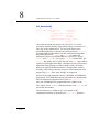
Components of the Monitor
This section describes each component of the monitor and the host
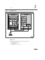
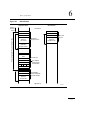
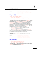
software that interfaces to the monitor. Figure 2-1 illustrates the monitor
components and their interfaces.
2-2
2
Overview
Figure 2-1
MON960 Structure
Target System
Host System
Monitor
MONDB
or
Core
Debugge r
Inte rfa ce Libra ry
Host De bugger
Inte rpre te r
Messa ge
La y er
User
Inte rfa ce
La y er
Communicatio n
Pa cket
Driv e r
Host
Inte rfa ce
Communicatio n
Pa cket
Driv e r
Dev ice
Te rminal
Driv e r
Emula to r
Dev ice Driv e r
Terminal
A5315-01
Monitor Core
The monitor core controls the basic operations of the monitor:
• initializing the processor
• starting execution
• handling faults and trace events
2-3
2
MON960 Debug Monitor User's Guide
•
•
•
saving and restoring user registers, setting and clearing hardware
breakpoints
reading and writing to user memory
handling runtime requests from the application
When the terminal interface or host interface needs to take steps that affect
the application, it calls the Core to perform the action. This arrangement
enables the monitor to operate consistently, regardless of the interface
used.
The user registers are copied into a global array when the application
stops, and they can be accessed by any part of the monitor. However, all
access to user memory is performed by calls to the Core. In this way,
access operations to user memory are controlled. For example, each call
to write to user memory is checked to see if it affects EEPROM, and then
the appropriate routine is called. For detailed information about the
monitor core, refer to Chapter 6, Theory of Operation.
User Interface
The User Interface (UI) is the monitor code that communicates with a
terminal. The User Interface parses ASCII commands from the user and
calls the monitor core to complete the requested actions. It translates
information or status from the Core into ASCII output.
Host Debugger Interface Library
The Host Debugger Interface Library (HDIL) implements the Host
Debugger Interface (HDI), which is described in Chapter 8. This interface
provides a high-level abstraction of the target. It can be linked into any
80960 debugger that uses the Host Debugger Interface to access its
execution environment.
The library generates messages to the target to perform actions required by
calls. In addition, it:
• maintains a software breakpoint table.
• maintains a memory cache.
• maintains a register cache.
2-4
Overview
•
•
2
handles runtime service requests from the application while it is
running.
provides a mechanism to interrupt the application while it is running.
The software breakpoint table is used for the following purposes:
• When the debugger requests user memory, the library replaces any
software breakpoints in the memory with the original code.
• When a software breakpoint is encountered, the library adjusts the IP
back to the address of the breakpoint.
• When execution is resumed after a software breakpoint is
encountered, the library (in cooperation with the target) restores the
original instruction, steps over the instruction, restores the breakpoint,
and continues execution, if appropriate.
Host Interface
The host interface processes messages from HDIL. It interprets the
command code, extracts the arguments from the message, and calls the
monitor core to complete the required actions. It responds to HDIL with a
message containing the status of the command and any results.
Downloading
The monitor and HDIL support downloading programs to a target using
one of three communication media:
1. serial
2. parallel
3. PCI bus
Of these three, only serial download is available from the monitor's user
Interface.
2-5
2
MON960 Debug Monitor User's Guide
Serial Download
Serial download is automatically available from any host debugger that
supports serial communication. Serial download is also available from the
User Interface with the following restrictions:
• A communications or terminal emulation program that supports
Xmodem transfer protocol must be used to connect to the UI, and
• The UI only downloads programs in Common Object File Format
(COFF). (ELF and b.out formats are not supported.) Furthermore, the
UI only downloads COFF programs with object records in littleendian host and target byte order.
Regardless of whether a debugger or the UI is used for serial download,
the target must provide a serial port connector and hardware to which the
monitor's serial communication API has been ported. With regard to
debuggers, HDIL must have been modified for the host's serial I/O API.
Appropriate hosts include:
• AIX* 3.2
• HP-UX* 9.X
• Solaris* 2.4
• SunOS* 4.1.X
• Windows 95 and Windows NT
Parallel Download
Host debuggers may choose to augment serial communication with
parallel download. The target must provide a parallel port connector and
hardware to which the monitor's parallel download API is ported.
Additionally, HDIL must have been modified for the host's parallel I/O
API. Appropriate hosts include:
• AIX 3.2
• HP-UX 9.X
• Solaris 2.4
• SunOS 4.1.X
• Windows 95 and Windows NT
2-6
2
Overview
Windows parallel download rates of as much as 40 Kbytes per second are
possible, while some UNIX hosts support more than 200 Kbytes per
second.
PCI Download
The PCI bus typically provides download transfer rates that range from
hundreds of Kbytes per second for small programs to more than one
Mbyte per second for large programs.
PCI download is available to any host debugger that supports PCI
communication. Host debuggers may choose not to support PCI
communication, but rather to augment serial communication with PCI
download.
These are the requirements for using PCI communications:
• The target must provide PCI hardware to which the monitor's PCI
communication API is ported.
• The host must provide a PCI bus and PCI-compliant BIOS.
• HDIL must have been modified for both the host and target's PCI I/O
API.
Currently, only the Cyclone PCI 80960DP, target and Windows host
combination meets these requirements.
Board Configurations
The monitor supports the following target boards:
Processor Board Name
Board Abbreviations
•
(CYSX, CYKX, CYCX, CYJX,
CYHX)
•
Cyclone EP80960BB, PCI80960DP
(Sx, Kx, Cx, Jx, Hx)
Cyclone IQ80960RP (RP)
CYRP
Note: This guide refers to the Cyclone and Cyclone PCI boards as the Cyclone boards.
To use the monitor on a target board other than those listed, you must first
modify, or retarget, the monitor program for your board. Steps for
completing that task are described in Chapter 5, Retargeting the Monitor.
2-7
2
MON960 Debug Monitor User's Guide
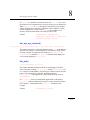
MONDB TCP/IP Communications Support
With version 3.1 of MONDB, a host can share an evaluation board with
another workstation. The host workstation must run the MONDB server
software along with the software shown in Figure 2-2. The remote
workstation communicates with the server via TCP/IP to access the
evaluation board. When needed, the server downloads the remote
workstation’s code to the evaluation board via PCI or serial connection.
For more information on using this feature, see Appendix B.
Figure 2-2
TCP/IP Server/Workstation Communication
Target System
Server
Monitor
MONDB
Server
Core
Interface Library
Host Debugger
Interpreter
Message
User
Interface
Layer
Communication
Packet
Driver
Layer
Host
Interface
Communication
Client
MONDB
or
Debugger
Interface Library
Host Debugger
Layer
Communication
Packet
Packet
Driver
Driver
Device
TCP/IP
Driver
Driver
Device Driver
A5317-01
2-8
Overview
2
ApLink Support
MON960 supports ApLink, a software and hardware debug probe for the
i960 processors. Because ApLink includes the MON960 debug monitor
on board, it makes i960 processor software development as simple as selfhosted development on a PC or workstation. By using ApLink, you avoid
having to port software or design specialized hardware into the target
system to use the monitor. Note that Intel does not ship ApLink source
code in standard MON960 releases. For more information on ApLink,
contact your local Intel sales representative.
ApLink works with source-level debuggers, such as gdb960. The sourcelevel debugger must support the Host Debugger Interface Library (HDIL).
2-9
3
Using the Monitor
3
Purpose
This chapter explains how to use the MON960 debug monitor’s user
interface (UI) to perform simple debugging tasks. You can connect the
target board to a terminal and use the monitor to set breakpoints, step
through programs, and examine memory and processor registers. You can
also use the monitor with a host system running a terminal program and
download application programs using Xmodem protocol.
If you are using a Cyclone evaluation board as your target, the source and
hexadecimal files that contain MON960 have been built for you and reside
in the directory you specified during installation. You need only produce
new EPROMs from the hexadecimal files and install those EPROMs on
your target board. The Specifying Build Options section, in Chapter 5, has
information about producing new EPROMs for your target board.
Connecting to the User Interface
Complete these steps:
1. Connect a serial cable from the host system to the target board. See
your target board documentation for details.
2. Run any standard terminal emulation program such as Windows
Terminal, and connect to the port where the target board cable is
connected.
3-1
3
MON960 Debug Monitor User's Guide
3. Set your communications settings to the following:
•
9600 to 115,200 baud
•
Data bits = 8
•
Stop bits = 1
•
No parity
•
Flow control = XON/XOFF
4. Enter six carriage returns (<Enter>).
MON960 responds with an invocation header and a command prompt.
You are now ready to enter any of the commands described in the sections
that follow.
Setting Breakpoints
The monitor enables you to set instruction breakpoints using the break
command with the address of the instruction. For example, the following
command sets an instruction breakpoint at address 80000040H:
=>break 80000040
You can set up to two instruction breakpoints on the i960 Sx, Kx, Cx, Jx,
and RP processors. The Hx processor supports six instruction breakpoints.
Enter break with no address to display current breakpoints.
Enter delete [address] to delete a breakpoint.
The break command sets a hardware instruction breakpoint using the
breakpoint register in the processor. This type of breakpoint stops
execution after the instruction is executed. See the break command in
Chapter 4 for more information on hardware instruction breakpoints.
You can also set software breakpoints, which stop before executing the
instruction where they are set. The monitor itself has no command to set
software breakpoints. Instead, software breakpoints are handled by the
3-2
3
Using the Monitor
host system via the Host Debugger Interface Library (HDIL). See the
Host Debugger Interface Library section in Chapter 8 for more
information on the HDIL. You can also set a software breakpoint
manually using the User Interface, as follows:
1. Replace the instruction where you want to break with a mark or
fmark instruction.
2. After execution stops at the breakpoint, replace the fmark instruction
with the original instruction word and set the instruction pointer back
to that instruction.
3. Single-step over the instruction with the step command. If you want
to retain the breakpoint, replace the instruction with the fmark
instruction again.
If you are using the i960 Cx, Jx, or RP processor, up to two data
breakpoints are available as well. If you are using the i960 Hx, six data
breakpoints are available. This type of breakpoint stops execution when
an address you specify with the bdata command is either read from or
written to. See the bdata command in Chapter 4 for more information on
data breakpoints.
Displaying Memory
The monitor's memory-display commands let you display memory in
several different formats, ranging from single bytes to quad words.
The following command displays four bytes of memory, beginning at
80000004h, and displays printable ASCII characters within those four
bytes.
=>dbyte 80000004#4
08008004 : 63
08008005 : 61
08008006 : 67
08008007 : 68
c
a
g
h
3-3
3
MON960 Debug Monitor User's Guide
The following command displays four quad words of memory beginning
at 80000010h:
=>dquad 80000010#4
08008010 : 080064e8
08008020 : 5c601e01
08008030 : 080064e8
08008040 : 5c601e01
8c603000
6563028c
8c603000
6563028c
00001000
5ca81615
00001000
5ca81312
5908408c
8a0a3200
5908408c
8c083000
Each memory-display command uses a single memory-access instruction
to access memory. For example, the dquad command invokes a fourword burst fetch on the burst bus of the i960 processor. The memory
display address must be aligned on a natural boundary.
The dasm command lets you disassemble i960 instructions stored in
memory. The monitor displays valid instructions in assembly-language
format, and invalid instructions in the assembly format .word with the
invalid instruction following in hexadecimal.
See Chapter 4 for more information on memory display commands.
Trace Events
The step command single-steps and breaks after every instruction. The
monitor also supports the following types of instruction traces:
3-4
Branch trace
breaks every time a branch is taken. A
conditional branch must take the branch
for a branch trace to occur. Branch-andlink instructions do not cause a branch
trace to occur. The trace branch on
command turns on branch tracing.
Call trace
breaks after any type of call or branchand-link instruction. The next
instruction to be executed is the first
instruction in the routine that was called.
The trace call on command turns on
call tracing.
3
Using the Monitor
Return trace
breaks any time a return instruction is
executed. No return trace is generated
for a return from a branch and link. The
trace return on command turns on
return tracing.
Supervisor call trace
breaks on supervisor calls that cause the
processor to change from user mode to
supervisor mode. The monitor, by
default, leaves your program running in
supervisor mode, so there is no mode
change and this trace fault does not
occur. If the program changes to user
mode and then does supervisor calls, this
trace fault occurs if the supervisor call
trace is enabled. A supervisor return to
user mode also triggers a supervisor
trace event. The trace supervisor on
command enables supervisor call
tracing.
After issuing a trace command, use the go command to continue executing
the program. When a trace event occurs, program control returns to the
monitor so you can look at memory or registers and determine the state of
the program. See Chapter 4 for more information on the trace command.
Loading MON960 Into Flash
Some i960 processor-based boards contain flash memory that you can use
to run MON960. For example, the Cyclone boards with Cx, Hx and Jx
CPU modules have flash memory. These boards are designed so that the
flash memory can appear at memory locations E0000000H and
F0000000H. You can load the flash memory with a PROM programmer
just like an EPROM, or you can load it while it is in the board. To load
MON960 into flash memory while it is in the board, you must have
another program or monitor installed that can do that. For example, if you
3-5
3
MON960 Debug Monitor User's Guide
are using the Cyclone board with a Cx CPU module, and you have a
previous version of MON960 installed in the CPU module, you can use it
to load the current MON960 into the expansion flash sockets.
Downloading MON960 to an Evaluation Platform
The sections that follow provide step-by-step instructions for updating the
version of MON960 in the PCI80960DP and IQ80960RP evaluation
platforms assuming a PC host enviroment.
PCI80960DP Evaluation Platform
NOTE. In order to write to flash on your Cyclone base board, you need a
12 volt power supply. Also, These instructions are used with the
CTOOLS 5.0 and MON960 3.1 toolsets and later.
1. Identify the flash on the Cyclone base board.
A blank flash chip ships on each Cyclone evaluation baseboard in
socket U22. To write MON960 to flash, you must move the blank
flash from socket U22 to socket U27.
2. Set the Cyclone baseboard voltage to 12 volts.
Locate the four-position DIP switch labeled S1. Flip S1.1 to the ON
position. This enables VPP to the Cyclone base board flash.
3. Power up the Cyclone evaluation base board.
Locate the four-pin connector that interfaces to a secondary power
supply labeled J6. Three of the connector pins connect to +5 VDC,
+12 VDC and ground. (On the PCI-SDK Platform, +12 VDC and
+5 VDC power is supplied through the edge connector.)
3-6
3
Using the Monitor
4. Edit Version.c. (Optional only if you rebuild MON960 from
source.)
•
Change directories to where the version.c file resides. The
default installation directory for CTOOLS is:
\intel960\src\mon960\common
Version.c contains the following information:
const char mon_version_byte =
nn;
/* version n.n = nn */
const char base_version[] = "MON960 n.n.n";
const char build_date[] = __DATE__;
•
Change the file contents to reflect that this is your version of
MON960. For example, change
const char base_version[] = "MON960 n.n.n";
to:
const char base_version[] = "MY MON960";
•
Save Version.c.
5. Build the new MON960 from source (optional).
By default the source for MON960 is located at:
c:\intel960\src\mon960\common. You may use the pre-built version of
MON960 there, or build a custom verion. To create a custom version:
•
Copy makefile.xxx to
c:\intel960\src\mon960\common\makefile.
where xxx is one of the following make files
makefile.ic (ic960 interface, COFF format)
makefile.ice (ic960 interface, ELF format)
makefile.gnu (gcc960 interface, COFF format)
makefile.gne (gcc960 interface, ELF format)
3-7
3
MON960 Debug Monitor User's Guide
•
Issue the commands:
nmake -f makefile cyhx
This creates a file called cyhx.fls.
1. Write the flash.
To write the flash, use the mondb.exe utility located in the
intel960\bin\ directory. If you are going to use the pre-built
MON960 files, they are located in the intel960\roms directory. For
example, if you used the default installation directory and are using
the pre-built MON960 files for the 80960Hx, enter:
mondb -ser com1 -par lpt1 -ef -ne c:\intel960\roms\cyhx.fls
The options in this command are:
-ser com1
use serial port 1
-par lpt1
use parallel port 1
-ne
no execute
-ef
erase flash
cyhx.fls
input flash filename
Note also that if you built a version of MON960 from the source code
as described previously, the cyhx.fls file will be located in the
c:\intel960\src\mon960\common\ directory.
2. Set board voltage back to +5 VDC.
Locate the four-position DIP switch labeled S1. Flip S1.1 to the OFF
position. This disables VPP to Cyclone EP base board flash and
protects your flash. Note that the PCI80960DP and i960 Hx
evaluation platforms do not boot when VPP is enabled and MON960
is running from the evaluation board flash.
3. Set board to boot from U27 socket.
Locate the four-position DIP switch labeled S1. Set S1.3 ROMSWAP
to the ON position. This exchanges the addresses of the CPU Module
3-8
3
Using the Monitor
ROM and the base board ROMs. When the switch is OFF the
processor boots from the CPU Module ROM; when the switch is ON
the processor boots from the base board ROMs.
4. Reset base board.
Locate the reset button labeled S2. Use this button to manually reset
the Cyclone base board and boot from the base board ROMs.
IQ80960RP Evaluation Platform
1. Identify the flash on the Cyclone base board.
A blank flash chip ships on each Cyclone evaluation baseboard in
socket U4. To write MON960 to flash, you must add a blank flash in
socket U3.
2. Set the Cyclone baseboard voltage to 12 volts.
Locate the four-position DIP switch labeled SW1. Flip SW1.1 to the
ON position. This enables VPP to the Cyclone base board flash.
3. Power up or reset the host to resest the Cyclone base board.
On the IQ80960RP Platform, +12 VDC and +5 VDC power is
supplied through the edge connector.
4. Edit Version.c. (Optional only to rebuild MON960 from source.)
•
Change directories to where the version.c file resides. The
default installation directory for CTOOLS is:
\intel960\src\mon960\common
Version.c contains the following information:
const char mon_version_byte =
nn;
/* version n.n = nn */
const char base_version[] = "MON960 n.n.n";
const char build_date[] = __DATE__;
3-9
3
MON960 Debug Monitor User's Guide
•
Change the file contents to reflect that this is your version of
MON960. For example, change
const char base_version[] = "MON960 n.n.n";
to:
const char base_version[] = "MY MON960";
•
Save Version.c.
5. Build the new MON960 from source (optional).
By default the source for MON960 is located at:
c:\intel960\src\mon960\common. You may use the pre-built version of
MON960 there, or build a custom verion. To create a custom version:
•
Copy makefile.xxx to
c:\intel960\src\mon960\common\makefile.
where xxx is one of the following make files
makefile.ic (ic960 interface, COFF format)
makefile.ice (ic960 interface, ELF format)
makefile.gnu (gcc960 interface, COFF format)
makefile.gne (gcc960 interface, ELF format)
•
Issue the commands:
nmake -f makefile cyrp
This creates a file called cyrp.fls.
6. Write the flash.
To write the flash, use the mondb.exe utility located in the
intel960\bin\ directory. If you are going to use the pre-built
MON960 files, they are located in the intel960\roms directory. For
example, if you used the default installation directory and are using
the pre-built MON960 files for the 80960RP, enter:
mondb -ser com1 -ef -ne c:\intel960\roms\cyrp.fls
3-10
3
Using the Monitor
The options in this command are:
-ser com1
use serial port 1
-ne
no execute
-ef
erase flash
cyrp.fls
input flash filename
Note also that if you built a version of MON960 from the source code
as described previously, the cyrp.fls file will be located in the
c:\intel960\src\mon960\common\ directory.
7. Set board voltage back to +5 VDC.
Locate the four-position DIP switch labeled SW1. Flip S1.1 to the
OFF position. This disables VPP to Cyclone EP base board flash and
protects your flash.
8. Set board to boot from U3 socket.
Locate the four-position DIP switch labeled SW1. Set SW1.3
ROMSWAP to the ON position. This exchanges the addresses of the
U4 and U3 ROMs. When the switch is OFF the processor boots from
the U4 ROM; when the switch is ON the processor boots from the
U3 ROM.
9. Reset the base board.
Reset the base board by rebooting the host PC. There is no reset
switch on the IQ80960RP evaluation board.
3-11
Monitor Commands
4
This provides you with detailed information on the MON960 commands,
including the elements of the command language, on overview of the
commands, as well as a complete command reference.
Elements of the Command Language
The elements of the command language include names, addresses, and
numbers, as described in the following sections.
Names
Names include command names and options. The monitor parses the
command line using only the first two characters of names. Therefore,
you can enter just the first two letters of each command or option. For
example, the following two commands are equivalent:
=>trace branch on
=>tr br on
Register names cannot be abbreviated.
Addresses
Addresses used in commands are hexadecimal and are accepted either
with or without a leading zero.
4-1
4
MON960 Debug Monitor User's Guide
Numbers
Numbers used in display commands, other than addresses, are decimals
unless otherwise noted. The default number of items displayed (for
example, bytes or words) is one, unless you specify a number.
Overview of Commands
Below is a listing of all MON960 commands, in their abbreviated forms:
ap
ap
ap
ap
bd
br
cf
da
db
dc
dd
de
di
di
do
dq
dp
ds
dt
ef
fi
fl
fr
fx
go
he
la
lm
mb
mc
md
4-2
en
sw
rs
wt
[address]
[address]
[address] #instructions
address [#bytes]
address [#characters]
address [#doublewords]
address
address [#words]
register
[offset]
address [#quadwords]
address [#shortwords]
address
address1 address2 worddata
address [#longreals]
address [#reals]
address [#extendedreals]
[address]
[command]
register value
register value
address
region value
address hex-value
4
Monitor Commands
md
mo
mo
po
pm
pp
pt
ps
qu
rb
re
rs
st
tr
ve
register hex-value
address [#words]
register
[address] [hex value]
bus# device# [function#]
[address] [hex value]
[address]
[address]
[option [on|off]]
Tables 4-1 through 4-4 group the MON960 commands according to
function and give a brief description of each command.
Table 4-1
Execution and Break Commands
Entry
Description
bdata
Sets a data breakpoint.
break
Sets an instruction breakpoint.
delete
Deletes a breakpoint.
go
Starts program execution.
pstep
Single steps one instruction or procedure.
step
Single steps one instruction.
trace
Sets trace options.
4-3
4
MON960 Debug Monitor User's Guide
Table 4-2
4-4
Memory Access Commands
Entry
Description
cflash
Checks flash memory.
dasm
Displays memory as assembler instructions.
dbyte
Displays memory in bytes.
dchar
Displays memory as ASCII characters.
ddouble
Displays memory in double words.
display
Displays memory or registers.
download
Downloads a program.
dquad
Displays memory in quad words.
dshort
Displays memory in short words.
dtriple
Displays memory in triple words.
eflash
Erases flash memory.
fill
Fills memory.
flong
Displays long real floating point numbers.
freal
Displays real floating point numbers.
fxreal
Displays extended real floating point numbers.
la
Sets a logical memory address register.
lm
Sets a logical memory mask register.
mbyte
Modifies one byte of memory.
mc
Sets a memory configuration register.
md
Modify register or one word of memory.
modify
Modifies memory or registers.
posttest
Runs the target post test.
registers
Displays registers.
4
Monitor Commands
Table 4-3
Table 4-4
Monitor Environment Commands
Entry
Description
help or ?
Displays help on monitor commands.
rb
Reboots the target board and communications link.
rs
Resets the target board.
version
Displays the monitor version.
.
Repeats the previous command.
ApLink Support Commands
Entry
Description
ap en
Modifies bits in the ApLink mode register.
ap sw
Moves an ApLink monitor from its boot-up region to a new
memory region.
ap rs
Manipulate an ApLink-compatible monitor.
ap wt
Alphabetical Command Reference
The MON960 commands are listed in alphabetical order. The entries
include the command syntax and examples of using the commands. The
examples include output from the monitor.
4-5
4
MON960 Debug Monitor User's Guide
ap en
ap en bit value
This command modifies bits in the ApLink mode register. It should only
be used in conjunction with an ApLink-compatible target. The valid range
of the bit parameter is 2-4 and the valid range of the value parameter is
0-1.
Bit 2 - Enable ApLink
(Active Low)
Bit 3 - Enable Timer interrupts
(Active Low)
Bit 4 - Enable Serial Break interrupt
(Active Low)
Refer to the ApLink User's Guide for further details.
Example
=> ap en 3 0
ap sw
ap sw mode region
This command moves an ApLink monitor from its boot-up region to a new
memory region and simultaneously switches to one of ApLink's supported
modes. The valid range of the region parameter is 1-1e; the valid range of
the mode parameter is 1-2.
For mode 2, all of the ApLink hardware except the ROM emulation
SRAM is moved to the new address region. The user can then download
new startup code into the SRAM from the IMI region.
4-6
Monitor Commands
4
For mode 1, all of the ApLink hardware is moved to the new address
region so that the user's startup code in the IMI region can be tested from
ROM. Refer to the ApLink User's Guide for further details.
Example
=> ap sw 2 2
ap rs
ap wt
ap rs
ap wt
These commands are used to manipulate an ApLink-compatible monitor
that meets the following preconditions:
1. It is modes 1 or 2, and
2. It has a new IMI in ROM or downloaded in the appropriate processor
boot region.
ap wt causes the monitor to configure itself internally in user mode (e.g.,
application mode) and then wait for a hardware reset. ap rs causes the
monitor to configure itself in user mode and then immediately reset the
target from the new IMI.
NOTE. ap wt causes the monitor to wait indefinitely for a target
hardware reset. In other words, the UI does not prompt for further input
until you complete a manual hardware reset.
4-7
4
MON960 Debug Monitor User's Guide
bdata
bd [address]
The bd command sets a data breakpoint at the specified address. The
monitor stops execution when the specified address is either read from or
written to. This command applies only to the i960 Jx/Cx/RP processors,
which have two hardware data breakpoints. The i960 Hx processor
supports six breakpoints. If you omit an address, the monitor displays the
current data breakpoints. To delete a data breakpoint, use the delete
command.
Example
=>bd 801c000
break
br [address]
The br command sets an instruction breakpoint. The address must be on
an instruction boundary. You can set up to two instruction breakpoints on
the i960 Kx, Sx, Cx, Hx, and Jx processors. Enter br with no address to
display all current breakpoints. To delete a breakpoint, use the delete
command.
Example
=>br 8008000
4-8
4
Monitor Commands
cflash
cf
The cf command checks to see if the flash memory is blank. When it is
not blank, the monitor displays the first and last addresses of programmed
memory and the total size of the flash memory.
Example
=>cf
Flash is programmed between 0x10000000 and 0x10005820
EEPROM size is 0x20000
dasm
dasm [address] #instructions
The dasm command disassembles instructions beginning at the specified
address. The default address is the current instruction pointer. The
address must be on a word boundary.
Example
=>da 8008000 2
08008000 : 5c601e01
08008004 : 6563028c
mov 1, r12
modpc r12, r12, r12
4-9
4
MON960 Debug Monitor User's Guide
dbyte
db address [#bytes]
The db command displays memory in bytes beginning at the specified
address. The display includes ASCII characters, if printable.
Example
=>db 8008006 2
08008006 : 63
08008007 : 65
c
e
dchar
dc address [#characters]
The dc command displays memory as ASCII characters.
Example
=>dc A000C000 10
A000C000 : ..FC..-x..
4-10
Monitor Commands
4
ddouble
dd address [#doublewords]
The dd command displays memory in double words at the specified
address. The address must be aligned on a two-word boundary.
Example
=>dd 8008000 2
08008000 : 5c601e01 6563028c
08008008 : 5ca81615 8c083000
delete
de address
The de command deletes an instruction breakpoint (for the Jx/Cx/Hx
processor, a data breakpoint) at the specified address.
Example
=>de 8008000
4-11
4
MON960 Debug Monitor User's Guide
display
di address [#words]
The di command displays memory in words beginning at the specified
address. The address must be aligned on a word boundary.
Example
=>di 8008000 2
08008000 : 5c601e01
08008004 : 6563028c
di register
The di command displays the contents of the specified register. The
registers command displays the valid register names.
Example
=>di pfp
pfp : 0801c500
download
do [offset]
The do command downloads a COFF file using the Xmodem protocol.
The offset is added to each word in the COFF file to form the actual load
address. This feature enables you to download position-independent code,
or download code to EEPROM that can be jumpered for different
addresses. When the monitor downloads a COFF file, it automatically sets
the IP to the start address given in the file.
4-12
Monitor Commands
4
Example
=>do
Downloading
(Invoke local download here. Bring
the host side into the foreground
running Xmodem and download the
file.)
-- Download complete -Start address is : 8008000
Downloading Flash Memory
The monitor supports programming flash memory when it is available on
the target board. Any memory-write command or download command
programs the flash memory when the address falls within the memory
space of the flash. The monitor checks to see that the flash memory is
erased before attempting to program it. If the flash is not erased, the write
fails.
dp
dp
Displays the current PRCB address.
4-13
4
MON960 Debug Monitor User's Guide
dquad
dq address [#quadwords]
The dq command displays memory in quad words beginning at the
specified address. The address must be aligned on a four-word
boundary.
Example
=>dq 80008000
08008000 : 5c601e01 6563028c 5ca81615 8c083000
08008010 : 080064e8 8c603000 00001000 5908408c
dshort
ds address [#shortwords]
The ds command displays memory in short words beginning at the
specified address. The address must be aligned on a two-byte boundary.
Example
=>ds 8008000 2
08008000 : 1e01
08008002 : 5c60
4-14
Monitor Commands
4
dtriple
dt address
The dt command displays memory in triple words beginning at the
specified address. The address must be aligned on a four-word
boundary. This alignment indicates that you can display only one triple
word at a time.
Example
=>dt 8008000
08008000 : 5c601e01 6563028c 5ca81615
eflash
ef
The ef command erases flash memory. The monitor prints an error
message if the board does not support flash memory or the flash memory
cannot be erased.
fill
fi address1 address2 worddata
The fi command fills memory from address1 to address2 with the
word value of worddata. If address1 = address2 then the monitor fills
one word at address1. The address1 must be aligned on a word
boundary.
4-15
4
MON960 Debug Monitor User's Guide
Example
=>fi 8008000 800800c a5a5a5a5
flong
fl address [#longreals]
The fl command displays long real (64-bit) floating-point numbers
beginning at the specified address. The address must be aligned on a
two-word boundary.
Example
=>fl 8008000 2
08008000 : 2.46506565e180
08008008 : -0.10557101e-249
freal
fr address [#reals]
The fr command displays real (32-bit) floating-point numbers beginning
at the specified address. The address must be aligned on a word
boundary.
Example
=>fr 8008000
08008000 : 6.02300001e23
4-16
Monitor Commands
4
fxreal
fx address [#extendedreals]
The fx command displays extended real (80-bit) floating-point numbers
beginning at the specified address. Although extended real numbers are
10 bytes, they must be aligned on quad word boundaries.
Example
=>fx 8008000 2
08008000 : 5.03696464e 19
08008010 : 6.40306565e 84
go
go [address]
The go command begins execution at the specified address. Enter go with
no address to begin execution at the current IP. When the monitor
downloads a COFF file, it automatically sets the IP to the start address
given in the file. See Chapter 7 for more information on program
execution.
Example
=>go 10008000
4-17
4
MON960 Debug Monitor User's Guide
help
he [command]
The he command displays help for a specified command. If you omit a
command, the monitor displays a summary of all commands.
Example
=>he rs
rs
Resets the board.
la
la regno value
The la command sets the contents of the specified logical memory
address register to the designated value. The valid range of regno is 0-1.
This command is valid for Jx/Hx processors only. Both command
arguments are assumed to be hex constants.
NOTE. It is important for consistent monitor operation that you use this
command correctly.
Example
=>la 0 a0000002
4-18
Monitor Commands
4
lm
lm regno value
The lm command sets the contents of the specified logical memory mask
register to the designated value. The valid range of regno is 0-1. This
command is valid for Jx/Hx processors only. Both command arguments
are assumed to be hex constants.
NOTE. It is important for consistent monitor operation that you use this
command correctly.
Example
=>lm 0 f0000001
mbyte
mb address
The mb command modifies one byte of memory. The memory address is
designated in hexadecimal. When the monitor displays the specified
address, you can enter a value in hexadecimal (34 in the example).
Example
=>mb 2800800c
2800800c : 34
4-19
4
MON960 Debug Monitor User's Guide
mcon
mc region value
The mc command sets the memory configuration register for the specified
region to the specified value. The valid range of region is 0 to 0xf. This
command is valid for the Cx/Hx/Jx processors only. When used for the Jx
processor, the region is automatically divided by two to map to the
supported range of that processor. Both command arguments are assumed
to be hex constants.
NOTE. It is important for consistent monitor operation that you use this
command correctly.
Example
=>mc a 800000
modify data
md address | register hex-value
The md command modifies one word in memory. When the monitor
displays the current value of the specified address, you can enter a new
value. Press Enter to leave the location unchanged.
Example
=>md 801c000 15
0801c000 : 00000002 : 5
0801c004 : 00000100 :
This example changes the contents of 0801c000 to 5 and leaves the
contents of 0801c004 unchanged.
4-20
Monitor Commands
4
Programming Flash Memory. The monitor supports programming
flash memory if it is available on the target board. Any memory-write
command or download command programs the flash memory when the
address falls within the memory space of the flash. The monitor checks to
see that the flash memory is erased before attempting to program it. If the
flash is not erased, the write fails.
md register hex-value
Modifies the specified register. When the monitor displays the current
value of the register, you can enter a new value. Press Enter to leave the
register unchanged. The monitor cannot modify floating-point registers
from the user interface.
The registers command displays the valid register names.
The register value is not changed until the application program resumes
execution.
NOTE. The mb and mo commands are not allowed in MONDB using the -d
option. Use the md command instead.
Example
=>md g0 12ffff78
4-21
4
MON960 Debug Monitor User's Guide
modify
mo address [#words]
The mo command modifies one or more words in memory. When the
monitor displays the current value of the specified address, you can enter a
new value. Press Enter to leave the location unchanged.
Example
=>mo 801c000 2
0801c000 : 00000002 : 5
0801c004 : 00000100 :
This example changes the contents of 0801c000 to 5 and leaves the
contents of 0801c004 unchanged.
Programming Flash Memory. The monitor supports programming
flash memory if it is available on the target board. Any memory-write
command or download command programs the flash memory when the
address falls within the memory space of the flash. The monitor checks to
see that the flash memory is erased before attempting to program it. If the
flash is not erased, the write fails.
mo register
Modifies the specified register. When the monitor displays the current
value of the register, you can enter a new value. Press Enter to leave the
register unchanged. The monitor cannot modify floating-point registers
from the user interface.
The registers command displays the valid register names.
The register value is not changed until the application program resumes
execution.
4-22
Monitor Commands
4
Example
=>mo r10
r10 : 00008000 : 1
po
po
[follow menu steps if applicable]
The po command runs the target’s power-on self test. The menus step you
through tests for each hardware component of the board. For more
information about setting up diagnostics, refer to Chapter 5 in this guide.
pstep
ps [address]
The ps command steps over a procedure. If the instruction is call,
callx, calls, bal, or balx, the entire called procedure is executed and
execution stops before the next instruction after the procedure. Otherwise,
one instruction is executed. When execution stops, the monitor displays
the next instruction to be executed.
Since this command uses a software breakpoint, which requires updating
the instructions, do not use it if the code is in ROM. If you do try to use it
in ROM code, the monitor reports a write verification error and does not
start execution.
4-23
4
MON960 Debug Monitor User's Guide
pm
pm [address] [hex value]
Displays the PCI shared memory space at offset address or writes a word
at offset address.
Example
=>pm 0:1234
pt
pt [address] [hex value]
Displays the PCI register space at offset address or writes a word to the
register at offset address.
Example
=>pt 0:1234
4-24
Monitor Commands
4
pp
pp bus# device# [function#]
Displays the PCI config space for the PCI device specified by the bus,
device, and function numbers. This option is for use with an i960 RP
processor only.
Example
=>pp 0 E 0
qu and rb
qu/rb
The qu or rb command resets the target board and leaves it waiting for
autobaud from a host or terminal. If you want to continue using a
terminal, press Enter two or three times to initiate the monitor sign-on. rb
is retained for compatibility. See also the rs and rb commands.
4-25
4
MON960 Debug Monitor User's Guide
registers
re
The re command displays the contents of all registers.
Example
=>re
g0 :
g4 :
g8 :
g12:
00000000
00000000
00000000
00000000
g1 :
g5 :
g9 :
g13:
00000000
00000000
00000000
00000000
g2 :
g6 :
g10:
g14:
00000000
00000000
00000000
00000000
g3 :
g7 :
g11:
fp :
00000000
00000000
00000000
0801c540
pfp:
r4 :
r8 :
r12:
pc :
0801c500
00000000
00000000
00000000
001f0003
sp :
r5 :
r9 :
r13:
ac :
0801c580
00000000
00000000
00000000
3b001001
rip:
r6 :
r10:
r14:
tc :
08000004
00000000
00000000
00000000
00000000
r3 :
r7 :
r11:
r15:
00000000
00000000
00000000
00000000
fp0:
fp1:
fp2:
fp3:
0.000000e
0.000000e
0.000000e
0.000000e
0
0
0
0
rs
rs
The rs command resets the target board. This command retains the
current baud rate and prints the monitor sign-on. It does not leave the
target waiting for autobaud. See also the rb command.
4-26
4
Monitor Commands
step
st [address]
The st command single-steps one instruction starting at the current IP or
specified address. When execution stops, the monitor displays the next
instruction to be executed.
Example
=>st 8000000
08000004 : 6563028c
modpc r12, r12, r12
trace
tr [option [on|off]]
The tr command turns a trace option on or off as follows:
branch
breaks every time a branch is taken.
call
breaks after any type of call or branch-and-link
instruction.
return
breaks any time a return instruction is executed.
supervisor
breaks on supervisor calls from user mode.
To display the current value of all trace options, enter trace. Enter
trace option without on or off to display the status of the specified
option.
To start execution with the specified trace options, use the go command.
4-27
4
MON960 Debug Monitor User's Guide
Example
=>tr br on
branch trace on
call trace off
return trace off
supervisor trace off
version
ve
The ve command displays the MON960 version number.
4-28
Retargeting the Monitor
5
This chapter explains how to retarget the MON960 debug monitor to run
on a non-Intel board. Intel boards include the Cyclone and Cyclone PCI
(refer to Table 5-1). This chapter also explains how to produce new
EPROMs for supported boards.
To retarget the monitor, you modify Intel-supplied source files to specify
addressing for your board's memory configuration. You can then use a
make utility to build a revised monitor that runs on your target board. This
chapter describes the following steps to retarget the monitor:
1. copying and modifying the board-specific source files
2. editing the makefile
3. copying the linker-directives file
4. configuring the makefile
5. making the monitor files
6. producing and installing new EPROMs containing the monitor
program
7. verifying monitor operation (if in User Interface mode)
Types of Source Files
The source code for the monitor is in the mon960/common directory. The
monitor contains three classifications of files as follows.
• files pertaining to all i960 processor targets (board-independent)
• files that depend on the target type (board-specific)
• hardware-specific files, such as the 82c54 and 85c36 timers
5-1
5
MON960 Debug Monitor User's Guide
When you retarget, you usually change the board-specific files, and you
may add hardware-specific files. In this manual, board is a place holder
for the name of your board. The following table lists the supported board
names with the abbreviations that can substitute for board:
Table 5-1
List of Board Names and Abbreviations
Processor Board Name
Board Abbreviations
•
(CYSX, CYKX, CYCX, CYJX,
CYHX)
•
Cyclone EP80960BB, PCI80960DP
(Sx, Kx, Cx, Jx, Hx)
Cyclone IQ80960RP (RP)
CYRP
Note: This guide refers to the Cyclone and Cyclone PCI boards as the Cyclone boards.
Code Areas Affected by Retargeting
When you retarget the monitor, the following areas of code may require
modification:
• memory configuration, which includes the following:
memory configuration in monboard.ld
bus configuration in board.h (for the Cx/Jx/Hx/RP only)
hardware-dependent addresses and constants in board.h
•
•
5-2
For more information, refer to the Memory Configuration section later
in this chapter.
board-specific data in board_hw.c, which includes the following,
described in the Board-specific Data section:
processor architecture, variable arch
architecture name, variable char arch_name[]
board name, variable char board_name[]
hardware-dependent routines, including, but not limited to:
the device-driver routines in 82510.c or 16552.c, described in
the Serial Device Driver Routines section
the LED routines in leds_sw.c, described in the Routines in
leds_sw.c section
5
Retargeting the Monitor
the routines for using flash memory, described in the Routines in
flash.c section
the parallel and PCI download routines. The parallel download
routines are described in the Routines in paradrvr.c section. For
information on the PCI download routines, see the section titled
MON960 Support for PCI Communication in Chapter 6.
The following sections discuss the portions of the monitor code that
require modification, and suggest modifications to that code.
Modifying Board-specific Files
To retarget the monitor for your board:
1. Duplicate the board-specific files that best match your hardware,
renaming these files to identify your target board. For use in these
examples, let's say your target is a Fred board containing an i960
Cx chip.
File Name
Contents and Example
board.h
hardware addresses and values
Example: copy cycx.h and rename it fred.h
board_hw.c
board name, architecture name, initialization,
reset, and hardware interface routines
Example: copy cycx_hw.c and rename it
fred_hw.c
monboard.ld
monitor linker-directives file for the board
Example: copy moncycx.ld and change it to
monfred.ld.
2. Modify the new board-specific files to support your target.
3. Select or add the hardware-specific files that support your target
board's features. Hardware-specific files are in the boardindependent MON960 source code.
5-3
5
MON960 Debug Monitor User's Guide
4. Change the makefile to reflect your new board name and the files
you selected to support it. Refer to the section later in this chapter
titled Creating the ROM Image.
5. Use the make command to build your retargeted MON960 files.
Refer to the section titled Creating the ROM Image later in this
chapter.
Board-specific Files
board.h
board.h, the board-specific include file, contains the following
information:
• constants that specify information about your board's hardware
addresses. You must change these constants to describe the target
board.
• constants you must define in order to use the monitor's flash memory
routines. Refer to the section later in this chapter titled Routines in
flash.c.
• constants that specify some of the fields of the boot control table (for
the i960 Cx/Jx/Hx/RP processors only). The boot control table fields
specified in board.h determine the board's bus configuration. Refer
to the next section, board_hw.c, for more information on those
constants.
• if your board uses the 82510 UART, definitions of constants that
support its use. Refer to the Serial Device Driver Routines section for
more information.
Note: If your board uses another serial device, you must provide the
driver to support it.
• if your board uses the 16552 DUART, definitions of constants that
support its use. Refer to the Serial Device Driver Routines section for
more information.
5-4
5
Retargeting the Monitor
•
•
•
#define values used by the routines in leds_sw.c . Those routines
are used to access and manipulate the LEDs on the board. Refer to
the section Routines in leds_sw.c for more information.
if your board supports parallel download, definitions of constants that
support its use. Refer to the section in this chapter titled Routines in
paradrvr.c for more information.
if you use the timer driver 82c54.c (EPCX) or 85c36.c (CYCX),
definitions of the following values that support its use:
Value
TIMER_BASE
CRYSTAL_TIME
TIMER_0_VECTOR
Setting
base address for timer chip
timer clock input frequency in MHz
interrupt vector set by MON960, e.g.
0XD2
TIMER_1_VECTOR
interrupt vector set by MON960, e.g.
0XC2
TIMER_0_IRQ
TIMER_1_IRQ
TIMER_0_OFFSET
TIMER_1_OFFSET
interrupt pin used by this timer
interrupt pin used by this timer
register address offset for each timer
register address offset for each timer
board_hw.c
Variables
The board_hw.c file contains variables that specify information about
your board. You must change the contents of these variables to describe
the target board.
5-5
5
MON960 Debug Monitor User’s Guide
Variable
Description
int arch
arch specifies the processor
architecture. The value of arch must be
one of the following:
• ARCH_CA
• ARCH_HX
• ARCH_JX
• ARCH_RP
The value of arch is used by the
monitor and host to determine what
registers and other capabilities your
board has.
If your target has a CA or CF processor,
use ARCH_CA . These values are defined
in hdi_arch.h in hdil/common . Do
not add an architecture type since the
host-side debuggers depend on these
values.
char arch_name[]
arch_name contains the name of the
processor architecture (Cx, Jx, Hx, or
RP). The name is printed in a banner
across the screen when the monitor
starts up.
char board_name[]
board_name contains the name you
specified for your board. The name
prints in a banner across the screen
when the monitor starts up.
char target_common_name[] target_common_name is a shortened
version of board_name[] .
target_common_name is reported to
debuggers using the
hdi_get_monitor_config() service.
5-6
5
Retargeting the Monitor
ADDR unwritable_addr
unwritable_addr is the address of a
read-only memory location that does not
fault the processor or hang the target
hardware when written to. This
information is reported to debuggers via
the hdi_get_monitor_config()
service. Set this variable to -1 if an
unwritable address is not available.
A date string, located in bld_date.c , prints in the banner when the
monitor starts up. You may use this variable to track retargeting code
revisions.
For the i960 Jx/Cx/Hx/RP processor, the file board_hw.c also contains
the boot control table. This table is declared const because it must be in
ROM, where it is read during processor initialization. During Monitor
initialization, it is copied to RAM, so the monitor may change fields as
required during operation. The fields of the control table that specify the
bus configuration are specified using defined constants from board.h. If
you need to change the bus configuration, do so in that file. Make any
other changes to the control table either in board_hw.c, or at runtime in
init_hardware .
5-7
5
MON960 Debug Monitor User's Guide
Routines
The board_hw.c file contains the following initialization routines that you
might need to change when retargeting the monitor:
void init_hardware(void)
int get_int_vector(int)
void init_imap_reg(PRCB *)
void board_reset(void)
int clear_break_condition(void)
void board_go_user(void)
void board_exit_user(void)
These routines isolate target-hardware dependencies in the monitor. If
necessary, modify these files to conform to the capabilities of your target
board. Below is an explanation of each routine in board_hw.c.
init_hardware()
void init_hardware(void)
This routine initializes the target board. The routine writes the processor
interrupt control registers with values applicable to the board. It also
initializes other board resources. See the programmer's reference manual
for your processor for information on programming the interrupt control
registers.
Before calling the init_hardware() routine, the monitor establishes
most of its own default variables. Thus, the values of these default
variables can be changed, if necessary, in the init_hardware() routine.
The init_hardware() routine must not initialize any hardware devices
that are not required for the operation of the monitor. Initializing these
other devices should be left to the application that is downloaded to the
target board once the monitor is running.
5-8
Retargeting the Monitor
5
get_int_vector()
int get_int_vector(int)
This routine returns the vector number of the interrupt that is generated
when a break is received by the serial port. The argument is not used.
When the Host Debugger needs to interrupt the application, it sends a
break signal to the target system. You can program a universal
asynchronous receiver transmitter (UART) to generate an interrupt when it
receives a break. The priority of this interrupt must be as high as possible
to ensure that the debugger can interrupt the application and regain control
even when the processor is running at high priority. If possible, use
priority 31 for the Kx version and NMI for the Jx/Cx/Hx/RP version.
This feature is not necessary for the basic operation of the monitor. If
get_int_vector() returns 0, this feature is disabled. You can code this
routine to return 0 until the rest of the monitor is working properly. If this
routine returns 0, then do not program the UART to generate any
interrupts.
The init_hardware() routine configures the interrupt mechanism. The
get_int_vector() routine returns the interrupt vector number assigned
to the UART, and the monitor fills in the appropriate interrupt vector into
the interrupt table. The serial_open() routine configures the UART to
generate an interrupt when a break is received.
If your target board requires special processing to clear the UART or an
interrupt controller, do that processing in the
clear_break_condition() routine. The monitor calls this routine to
perform any special processing required to clear an interrupt condition.
init_imap_reg()
void init_imap_reg (PRCB *prcb)
This function is required for the i960 Jx/Cx/Hx/RP processors only.
5-9
5
MON960 Debug Monitor User's Guide
This routine initializes the proper IMAP register field in the control table
used for the monitor's interrupt. The routine is called at initialization and
when the PRCB is changed. The routine is passed a pointer to the new
PRCB, which it uses to locate the new control table.
You need not change this code if you define BRK_PIN and BRKIV correctly
for your target board. If your target board uses NMI for the monitor's
interrupt, this routine does not need to set up for the next interrupt.
board_reset()
void board_reset (void)
This routine resets the monitor target. The routine does not return a value.
If the target hardware does not support resetting the processor, this routine
restarts the i960 processor.
To restart the i960 Jx/Cx/Hx/RP processor, this routine calls the following
routine:
send_sysctl(0x300, reinit, &rom_prcb)
See your processor user’s manual for information on the sysctl
instruction.
clear_break_condition()
int clear_break_condition(void)
This routine clears an interrupt from the serial port. The routine is called
when an interrupt is received from the serial port. It completes any special
processing required to clear the interrupt condition in the UART or
interrupt controller. It must ensure that any null characters or framing
errors created by the start or end of the break are cleared in the UART. In
the example code, this work is done by the serial_intr() routine in the
82510.c file.
If the interrupt was caused by a break received from the host, the routine
returns TRUE. If the interrupt was caused by some other condition, such as
overrun, the routine returns FALSE.
5-10
Retargeting the Monitor
5
NOTE. You need not program the UART to generate an interrupt on
overrun or other error conditions. However, some UARTs do not allow
you to disable these interrupts, so the monitor ignores them.
board_go_user()
void board_go_user(void)
The monitor calls this routine each time execution returns to the
application program. You can use this routine to light an LED to indicate
that the application program is running, or perform other board-specific
requirements to execute an application program. On the i960
Jx/Cx/Hx/RP processor, if the break interrupt priority is not NMI, this
routine enables the appropriate interrupt in the saved copy of the IMSK
register, as in the following code:
register_set[REG_IMSK] |= IMSK_VAL;
board_exit_user()
void board_exit_user(void)
This function performs any required board-specific actions when
execution returns from the application to the monitor. The routine is
called when execution returns to the monitor.
Memory Configuration
monboard.ld
This linker-directives file is specified in the makefile by the line
BOARD_ROM_LD= filename. For example, make a copy of moncycx.ld
in which you have modified the memory ranges specified at the beginning
of the file. The linker-directives file is discussed further in the next
section, Defining Memory Configuration.
5-11
5
MON960 Debug Monitor User's Guide
Defining Memory Configuration
Define the target memory configuration by assigning values to the
following memory configuration variables in monboard.ld, the
linker-directives file (for example, moncycx.ld):
Variable
Description
ibr
address of initialization boot record
(Cx/Jx/Hx/RP only). The ibr addresses are
listed below and should never be changed.
eprom
Processor
ibr Address
Cx
0xffffff00
Jx/Hx/RP
0xfeffff30
base address and size of EPROM space. The
size requirement for the monitor is
approximately 100 kilobytes.
You can reduce the monitor size by linking
without some of the features, for example, the
User Interface. Removing all available features
results in a minimum monitor size of 32
kilobytes. See the Specifying Makefile Build
Options section for more information on building
a minimum monitor. See the Creating the ROM
Image section for directions on using the
makefile to relink the monitor.
5-12
data
base address and size of monitor initialized data
space. The size requirement is about one
kilobyte.
bss
base address and size of monitor uninitialized
data space. The size requirement is about 12
kilobytes.
5
Retargeting the Monitor
If you have room, reserve a portion of the beginning of RAM to enable
future expansion. For example, reserve 32 kilobytes to accommodate the
monitor made with all features enabled.
Several other symbols are defined in the linker-directives file:
pre_init
set to the address of the pre-initialization code, if
it is required. See the Board Initialization
section for information on this pre-initialization
code.
initial_stack
defines the stack that is used after initialization.
Define it as _monitor_stack.
_checksum
value placed in the initial memory image (IMI)
as part of the checksum.
You can edit the linker-directives file to change the addresses for some of
these variables to match your target board. If you are retargeting the
monitor for i960 Jx/Cx/Hx/RP evaluation boards, the board.h file defines
the bus configuration values for the processor. When you change the
settings in the monboard.ld file, duplicate those changes in the board.h
file as well.
The cx_ibr.c/jx_ibr.c/hx_ibr.c/rp_ibr.c file contains the
initialization boot record for the i960 Cx/RP/Hx/RP processor. You need
not change this file because the code is recompiled using the definitions in
board.h. See the programmer's reference manual for your processor for
information on the initialization boot record.
The monitor normally resides in EPROM on the target board. The monitor
stores its own data and a copy of the i960 processor data structures in
target RAM. Figure 5-1 shows the memory configuration for the Cyclone
i960 Sx, Kx, Cx, Jx, and Hx boards. Figure 5-2 shows the memory
configuration for the i960 RP Cyclone board.
5-13
5
MON960 Debug Monitor User's Guide
Figure 5-1
Memory Map for Cyclone i960 Sx/Kx/Cx/Jx/Hx Boards
F000 0000H
EFFF FFFFH
CPU Module
Flash Boot ROM
for 80960Cx/Jx/Hx
Expansion Flash ROM
E000 0000H
Expansion
Flash ROM
Reserved
D000 0000H
Squall Module
C000 0000H
B00C 0000H
B008 0000H
B004 0000H
B000 0000H
Reserved
Parallel Port
CIO
Serial Port
Flash Socket 1 (U27)
Flash Socket 2 (U22)
E004 0000H
E000 0000H
DRAM
A000 0000H
Reserved
1000 0000H
0000 0000H
CPU Module Flash Boot
ROM for 80960Kx/Sx
A5318-01
5-14
5
Retargeting the Monitor
Figure 5-2
Memory Map for IQ80960RP Cyclone Boards
Processor Memory
Mapped Registers
F000 0000H
ROM, Flash ROM
and
ROM B
Processor Registers
F000 0000H
On-board
E000 0000H
Devices
FEFC 0000H
ROM A
FEF8 0000H
Reserved
F000 0000H
Reserved
DRAM Status Register
(read only)
B000 0000H
DRAM
LED Register
(write only)
A000 0000H
Reserved
9002 0000H
E004 0000H
UART
E000 0000H
ATU Outbound
8000 0000H
Translation Windows
ATU Outbound Direct
Addressing Windows
0000 1000H
Peripheral Memory
Mapped Registers
0000 0800H
Reserved
0000 0400H
Processor Internal
Data RAM
0000 0000H
A5316-01
Creating the ROM Image
After modifying source files as necessary for your target board, create the
ROM image of the monitor according to the following steps:
1. Edit the makefile.
5-15
5
MON960 Debug Monitor User's Guide
2. Copy the linker-directives file (monboard.ld).
3. Configure the makefile.
4. Make the monitor files using a make utility.
5. Produce new EPROMs.
6. Install new EPROMs.
MON960 includes a makefile that can build a monitor for any of the
evaluation boards in the /mon960/common directory.
The supplied makefile can build MON960 for any of the supported boards.
For example, if you want to build MON960 for a Cyclone board with a Cx
CPU module, either use the supplied makefile, or configure a new one as
described in the following steps; then type make cycx. If you do not
change the makefile, advance to the step on the next page called Configure
the Makefile. If you do change the makefile, go to the next step, Edit the
Makefile.
NOTE. The makefile has been tested on UNIX systems with the standard
make utility, and on Windows systems with the Microsoft make utility,
NMAKE, R1.20. If you use some other make utility, the makefile may
require modification.
To use the supplied makefile, do the following:
Edit the Makefile
If you have retargeted the monitor, edit the makefile as follows:
1. Duplicate the group of make commands for the evaluation board that
is most similar to your target board. For example, if your target board
uses the i960 Cx processor, duplicate the group of make commands
under the heading CYCX Evaluation Board.
2. Replace all the board strings in your new commands with the
appropriate string for your target board. For example, replace all
occurrences of CYCX with FRED and all occurrences of cycx with
5-16
Retargeting the Monitor
5
fred. You may want to remove lines from the makefile. For
example, you may not want the FRED_POST_OBJS=... command if
you do not intend to write power-on self-tests for your target board.
3. Edit the line BOARD_OBJS=... to match the characteristics of your
target board and desired monitor. For example, the CYCX line is as
follows:
CYCX_OBJS= ${CX_BASE_OBJS} ${CX_HI_OBJS}
${CX_UI_OBJS} ${CYCX_BOARD_OBJS}
${COMMON_C145_OBJS} ${CYCX_TEST_OBJS}
If you do not want to link in the User Interface, replace
${CX_UI_OBJS} with ${NO_UI_OBJS}. Therefore, a reasonable
line might be:
CYCX_OBJS= ${CX_BASE_OBJS} ${CX_HI_OBJS}
${NO_UI_OBJS} ${CYCX_BOARD_OBJS}
${CYCX_TEST_OBJS} ${COMMON_C145_OBJS}
Copy the Linker-directives File
If you have retargeted the monitor, you also need to make a copy of the
linker-directives file that reflects the memory configuration of your target
board. The linker-directives file is specified in the makefile by the line
BOARD_ROM_LD= filename. For example, make a copy of moncycx.ld
in which you have modified the memory ranges specified at the beginning
of the file.
For a detailed explanation of the memory configuration variables in the
linker-directives file, refer to the section earlier in this chapter called
Defining Memory Configuration.
Configure the Makefile
Configure the makefile by entering the following command. Its variables
are described below.
make make [HOST=host] [TOOL=tool] [obj_fmt=format]
5-17
5
MON960 Debug Monitor User's Guide
Variable
Description
host
signifies the host computer, UNIX or Windows,
on which you are running the make utility.
tool
signifies the toolset you are using to build the
monitor. The tool option can be any of the
following:
intel
used to build with the
CTOOLS960 tools
gnu
used to build with the
GNU/960 tools
format
specifies the object module format as either:
elf
generates ELF object modules
coff
generates COFF object
modules
The defaults for the make make are unix, gnu and coff.
This make command creates a new makefile that enables the appropriate
make commands for your combination of host and toolset. The original
makefile is saved as Makefile.old.
The Minimum Monitor
Include the following in your makefile to build a minimum monitor. You
may use m_epcx and an example of a minimal monitor.
5-18
5
Retargeting the Monitor
Table 5-2
Minimum makefile Symbols
Symbol
Purpose
XX_UI_OBJS
adds the modules that create the
MON960 User Interface
or
XX_HI_OBJS
adds the modules that provide the
MON960 Host Debugger Interface
PCI_OBJS
allows the use of PCI communication
or
SERIAL_OBJS
allows the use of serial
communication
NO_PARALLEL_OBJ added to the
BOARD_OBJS list
suppresses the use of parallel code
NO_FLASH_OBJS
disables flash memory
NO_TIMER_OBJS
disables use of your target’s timers
NO_POST_OBJS
prevents the use of power-on self
test with your monitor
NO_APLINK
omits the code for ApLink support
XX_BASE_OBJS
include the basic object files
board_hw.o
includes the correct board
initialization code
FIRST_OBJS
includes the monitor’s initialization
boot record and startup code
Specifying Makefile Build Options
You may want to specify build options in the makefile, depending on
available EPROM space and the desired functionality of your target board.
Specifying these build options adds functionality, but the tradeoff may be
increased EPROM space requirements or decreased performance. The
following paragraphs describe the build options that you may enable or
disable in the makefile for each target board.
5-19
5
MON960 Debug Monitor User's Guide
Table 5-3
Optional makefile Symbols
Symbol
Purpose
XX_UI_OBJS
adds the modules that create the
MON960 User Interface
NO_UI_OBJS
suppresses the User Interface
HELP in UI_MAIN.C
includes online help in the User
Interface. This option is enabled in
this file as the default. If you are
short of EPROM space, you may
want to comment the following line in
UI_MAIN.C:
#DEFINE HELP
XX_HI_OBJS
adds the modules that provide the
MON960 Host Debugger Interface
NO_HI_OBJS
suppresses the Host Debugger
Interface
TARGET PARA.O in the
BOARD_OBJS list
adds the code that creates the
parallel download functionality of the
monitor
NO_PARALLEL_OBJ in the
BOARD_OBJS list
suppresses use of parallel code
ALLOW_UNALIGNED
causes the monitor to support
unaligned references to memory. For
the Jx/Cx/Hx/RP architecture, this
also sets the Mask Unaligned Fault
bit in the PRCB
Commented ALLOW_UNALIGNED
causes the monitor to generate an
error when the user requests an
unaligned memory access. On the
Jx/Cx/Hx/RP architecture, this clears
the Mask Unaligned Fault bit in the
PRCB, causing the processor to fault
if the application makes an unaligned
reference.
continued ☛
5-20
5
Retargeting the Monitor
Table 5-3
Optional makefile Symbols (continued)
Symbol
Purpose
This option is enabled (defined) in the
makefile as the default:
ALLOW_UNALIGNED= DALLOW_UNALIGNED
NO_PCI_OBJS
suppresses the use of PCI
communication
PCI_OBJS
allows the use of PCI communication
Uncommenting the lines
TIMER_HW=$(TARGET)timr.o and
HJ_TIMER=-DHJ_TIMER
enables the use of Jx, Hx, or RP onchip timers
Uncommenting the line
TIMER_HW=$(TARGET)8536.o
allows the use of the Cyclone board
85c36 timers
FLASH_OBJS
enables the use of flash memory
NO_FLASH_OBJS
disables flash memory
SERIAL_OBJS
allows the use of serial
communication
_NO_SERIAL_OBJS
disables serial communication
TIMER_OBJS
allows the use of your target’s timers
NO_TIMER_OBJS
disables the timers
POST_OBJS
adds power-on self test code to your
monitor
NO_POST_OBJS
prevents the use of power-on self
test with your monitor
USER_COMM
sets the make file to link a user
program to MON960, using a
specified communication channel
USER_OBJS
lists the user program objects used to
link into MON960
5-21
5
MON960 Debug Monitor User's Guide
You may also add LED functionality to your board by adding the
following to the board.h file. The default is no LED functionality.
Table 5-4
LED Symbols
Symbol
Purpose
SWITCH_ADDR
allows you to use the target board’s
switches
LED_8SEG_ADDR
allows you to use the eight-segment
LED on your board
LED_1_ADDR
allows you to use the individual LEDs
on your board
BLINK_PAUSE
allows you to use blink-pause-wait
loops to distinguish LED changes
Make the Monitor Files Using a Make Utility
You are now ready to make the monitor files. Enter the command:
make board
is the name you used when you edited the
makefile (for example, fred).
This command creates the following output files:
board
board
the COFF file containing the complete monitor.
board.ima
the binary image file of the complete monitor.
the Intel hexadecimal object-file format that
contains the complete monitor.
This command creates additional, smaller .hex files if the specified target
board is a Cyclone with an Sx or Kx CPU module, which uses multiple
EPROMs. These .hex files contain the same information as board.hex,
but split the information across the EPROMs.
board.hex
5-22
Retargeting the Monitor
5
Most PROM programmers can use hexadecimal-format files.
This command also creates a board.fls file for the Cyclone board,
which is the COFF file prepared for downloading into flash memory on
those target boards.
Produce New EPROMs
After using the makefile to produce the .hex file, you can program any
EPROMs needed for your target board using the .hex file and a PROM
programmer. Intel provides separate .hex files i960 Cx, Hx, Jx, and RP
modules. Each file supports both standalone and PCI boards. You can use
the single .hex file if your PROM programmer can split the code among
the EPROMs.
Install the New EPROMs
Finally, install the EPROMs on your target board as follows:
1. Write the monitor image into the EPROM(s) needed for your target
using a PROM programmer and the .hex file generated by the
makefile.
2. Install the EPROM(s) on your target board. Then, connect your target
board to a terminal using an RS-232C cable. Ensure that the monitor
is running properly on your target board as described in the Verifying
Monitor Operation section.
5-23
5
MON960 Debug Monitor User's Guide
NOTE. Although you could run the gdb960 debugger now, do not do so
until you have used MON960 enough to be sure that your retargeting was
successful. The debugger adds levels of complexity that can interfere with
verifying that the monitor is running correctly.
Debugging the Monitor
Once the monitor is in EPROM on the target board, you can connect a
terminal to the target board and power up the target board. If your
terminal is set to 9600 baud, you should see the string MON960 after the
system initializes. If your terminal is set to some other baud rate, this
string displays only nonsensical characters. In either case, press Enter six
times. The monitor signs on with the monitor version number listed in the
sign-on line in the form:
Mon960 monitor for the Intel i960 processor
Version version board_name date
Copyright 1995, Intel Corporation
Variable
Description
processor
is the name of the i960 processor type.
version
is the version number of the monitor core.
board_name
is the value of the variable board_name
specified in the board_hw.c file.
date
is the build date of the monitor.
The following sections can help you isolate problem areas in the code.
Verifying Monitor Operation
To verify that the monitor is running correctly on your target board,
perform the following operations with the User Interface commands listed
in Chapter 4. Many of these operations are also discussed in Chapter 3.
1. Read memory from EPROM space.
5-24
Retargeting the Monitor
2.
3.
4.
5.
6.
7.
8.
9.
10.
11.
12.
13.
14.
15.
16.
5
Read memory from flash space.
Read memory from RAM space.
Write data to RAM space.
Write data to flash space.
Check flash memory.
Erase flash memory.
Download code to RAM space using the serial interface.
Set a breakpoint.
Execute to the breakpoint.
Display the registers.
Single step an instruction (step command).
Single step a procedure (pstep command).
Delete the breakpoint.
Download code to the flash space using the serial interface.
Download code to RAM and/or flash space using the parallel
interface. Perform the download using the MONDB utility described
in Appendix B.
NOTE. On the Cyclone boards with a Cx, Hx, Jx, RP CPU module, you
can download the <board>.fls file, and then use the ROM swap switch
to boot the monitor out of flash memory instead of EPROM. See the
Loading MON960 Into Flash section in Chapter 3 for instructions on
loading MON960 into flash memory.
Troubleshooting Host-target Serial Communication
Problems
The following problems can occur between the host and the target.
You do not see the Mon960 string when connected at 9600 baud.
5-25
5
MON960 Debug Monitor User's Guide
Check the following:
• That the baud rate of the terminal is 9600 baud. At other baud rates,
you do not see the Mon960 message, because it prints before autobaud
is done.
• That the terminal program, if you are using one, is configured to use
the proper communications port.
• That the serial connection is correct. See the user manual for the
board for information on the serial-cable connection. Be sure to use a
null-modem adapter, if necessary.
If you have retargeted the monitor, check the following:
• Monitor initialization routines.
• Your serial_init() routine, and serial_open() if you changed
it.
• Your serial_putc() routine, and serial_write(), if you
changed it.
• If you changed serial_open() routine, ensure that it sets the baud
rate to 9600 and calls serial_write() with the Mon960 string.
You see the Mon960 string, but do not see the sign-on message when
you press the Enter key.
Check the following:
• Your serial_getc() routine, and serial_read(), if you changed
it.
• Your serial_set() routine, and serial_baud(), if you changed
it.
You must always press Enter six times to get a response. The autobaud
mechanism cannot recognize the baud rate fully when you enter only one
character. You must enter the subsequent Enter key presses within one
second after the first for the multiple entry to be recognized.
A terminal works properly, but MONDB does not connect.
The MONDB program is the download-and-go software utility included
with the monitor.
• Check the specification of the communications port to MONDB.
5-26
5
Retargeting the Monitor
•
•
•
•
•
Try a lower baud rate. Some hosts cannot keep up at the maximum
supported baud rate.
Check that the code in serial_read() that handles timeouts is the
same as the code provided.
Check the routine calc_looperms().
If you are using a non-standard communications board in your
Windows, or UNIX host, check your supported configurations.
Check the -freq invocation option. The freq option sets the serial
crystal frequency. A non-standard communications board is one that
does not use a 1.8432 MHz crystal.
PCI Retargeting
If your PCI hardware includes two mailbox registers and a doorbell
register, change just the addresses for CYCLONE_TARGET_STATUS_MB and
CYCLONE_TARGET_DATA_MB in the board.h include file. The 80960RP
and PLX9060 chip provide this support. Otherwise, rewrite the routines in
pcidrvr.c (see Chapter 6) to match your PCI hardware.
PCI Hardware Resources Reserved By MON960
*
Target
Resource(s)*
Cyclone PCI80960DP
Mailbox registers 6 & 7 and doorbell bits
30 & 31 in both the local-to-PCI and PCIto-local doorbell registers.
Cyclone IIQI80960RP
Inbound Mailbox register 1 and outbound
Mailbox register 1. Doorbell interrupt bits
30 & 31 in both the local-to-PCI and PCIto-local doorbell registers. For more
information on these registers, refer to the
ATU chapter in the i960 RP Processor
User’s Manual.
These hardware resources are reserved exclusively for MON960 and should not be modified by
programs executing on the target.
5-27
5
MON960 Debug Monitor User's Guide
Board Initialization
At reset, the i960 processor completes a checksum self-test, reads pointers
from the initial memory image (IMI), and then begins executing user
instructions at the boot address. Boards designed for the i960 architecture
normally include a mechanism to signal assertion of the i960 processor
FAIL# pin. The Intel evaluation boards implement this mechanism with
an LED. This mechanism enables you to determine if the processor
successfully read the IMI and reached the boot address.
The boot address is _start_ip in the init.s file. Normally, this file
needs no modification. The code in init.s checks the symbol pre_init
to see whether any code must be executed before monitor initialization. If
pre_init is not zero, init.s calls this code via the instruction balx
pre_init,g14.
The pre_init() routine performs any functions that must be completed
before monitor initialization. For example, it may perform DRAM
initialization or board-level self-tests, such as memory tests or ROM
checksum verification.
The pre_init() routine may be written in assembly language, since it is
entered via a branch-and-link instruction. The routine must preserve the
global registers g14 and g11. The g14 register is used as the return
address, and the g11 register contains processor revision information for
processors that support revision information.
The pre_init() routine can be written in C, but it requires special
considerations, such as:
• Some boards need initialization before using RAM.
• Static data is not initialized.
• The runtime library is not initialized.
• The arithmetic controls register is not initialized.
• The pre_init() routine is called with a balx instruction, and it must
save registers g14 and g11 (described previously).
• No stack is available, so you should not use stack or call instructions.
5-28
Retargeting the Monitor
5
NOTE. For all i960 compilers, if you want to call a C language routine,
you must save the value of g14 in another register and then clear the g14
register before the call. The pre_init() routine must not call any C
library routines, because they are not yet initialized.
Put any initialization routines and non-application initialization routines
that need not be completed before monitor initialization in the
init_hardware() routine. The init_hardware() routine is called
from main and can use C and C library support.
After the pre-initialization code returns, the init.s file sets up the stacks,
initializes the C run-time environment, copies the processor data structures
to RAM, and re-initializes the processor for the new data structure
locations.
Finally, init.s branches to _main, which calls the init_hardware()
routine in the board_hw.c module. If necessary, you can modify the
init_hardware() routine and other hardware-dependent routines in
board_hw.c.
The next two sections describe board-specific data and routines in
board_hw.c that might need modification.
Routines in leds_sw.c
The routines listed in this section are for accessing and manipulating the
LEDs on the board. The LEDs provide diagnostic information. All the
routines in this section are based on #define values from board.h.
These functions are for display purposes only and may be stubs that do not
affect monitor operation.
The following routines are in the file mon960/common/leds_sw.c:
unsigned char read_switch ()
void blink (int n)
void blink_hex (int n, int size)
5-29
5
MON960 Debug Monitor User's Guide
void blink_string (char *cha_ptr, int size)
void fatal_error (char id, int a, int b, int c, int d)
void led (int n)
void led_debug (char id, int a int b int c int d)
void led_output (char id, int a int b int c int d)
void leds (int val, int mask)
void pause()
NOTE. If your code does not define a particular address in Table 5-6,
the code does nothing with it.
The following table provides a listing of defined symbols and their uses:
5-30
5
Retargeting the Monitor
Table 5-5
Define Symbols for LED Use
Define Symbol
Purpose
SWITCH_ADDR
Byte address at which to read switch values
LED_8SEG_ADDR
Byte address at which to write eight-segment
values
LED_1_ADDR
Byte address at which to write first N LEDs
LED_2_ADDR
Byte address at which to write second N LEDs
LED_3_ADDR
Byte address at which to write third N LEDs
LED_4_ADDR
Byte address at which to write fourth N LEDs
LEDS_SIZE
Number of LEDs per address
LEDS_MASK
Mask LED_SIZE bits for writes to
LEDS_N_ADDR
LEDS_ON_IS_0
Defines 0 as turning on LEDs. 0 normally turns
off LEDs
BLINK_PAUSE
Loop count so LEDs may be seen.
DOT
Eight-segment LED display "." (dot)
CLR_DISP
Clear eight-segment LED display
DISPLAY0 to DISPLAYF
Display eight-segment LED value corresponding
to value represented in the name of the define
symbol
read_switch
unsigned char read_switch ()
This routine obtains user input through the switches. That information is
used to determine the initialization selection for the board. The routine
returns the inverted value read from the dipswitch defined in <board>.h
as SWITCH_ADDR.
5-31
5
MON960 Debug Monitor User's Guide
blink
void blink (int n)
This routine is used to display information on seven-segment LEDs. For
example, displaying an 8 on an LED could signify that board initialization
is complete. The routine displays the number long enough for the user to
read it, and then erases it from the LED.
blink_hex()
void blink_hex (int n, int size)
This routine displays user-readable hex number for debugging. It blinks
hex value n for size digits onto an eight-segment LED, or individual
LEDs. The sequence is a long pause, then a series of size hex digits,
followed by another pause while the user reads the output.
blink_string()
void blink_string (char *cha_ptr, int size)
This routine displays a string value used for debugging. Either the string
displays on the eight-segment LED, or individual LEDs display the upper
ASCII hex digit, followed by the lower ASCII hex digit, for size number
of bytes.
fatal_error()
void fatal_error(char id, int a, int b, int c, int d)
The monitor calls this function if an unrecoverable error occurs. This
routine does not return.
Currently used id values are 1 through 4. The id values 5 through 127
are reserved for future use by MON960, and the values 128 through 255
are available for user-defined error handling. The following table
provides a list of values for id, the contents of the other parameters, and a
description of the cause of each error.
5-32
5
Retargeting the Monitor
Table 5-6
Arguments for fatal_error()
id
a
b
c
d
Cause:
1
fault_type
ip
pc
fp
Unhandled fault
2
vector #
ip
pc
fp
Unhandled interrupt
3
no other args
HI console output failed
4
no other args
Board reset failed
If the monitor is not connected to a Host Debugger, the fatal_error()
routine attempts to print the message for id to standard output. Then the
eight-segment LED displays three seconds of blank followed by the
contents of each argument to fatal_error(). The display separates
each argument from the next by displaying a period. The values in id and
A through D appear in hexadecimal. The following table shows the
sequence of display:
Table 5-7
LED Display for fatal_error()
Display:
Argument Represented:
3 seconds blank
.
xx
id (2 hex digits)
.
xxxxxxxx
A (eight hex digits)
.
xxxxxxxx
B (eight hex digits)
.
xxxxxxxx
C (eight hex digits)
.
xxxxxxxx
D (eight hex digits)
5-33
5
MON960 Debug Monitor User's Guide
led()
void led(int n)
This routine displays n as a hex digit to the LEDs defined in board.h as
either LED_8SEG_ADDR or LED_1_ADDR. If n is greater than 16, a dot
displays in the eight-segment LED. Entering -1 clears the display.
led_debug
void led_debug (char id, int a int b int c int d)
This routine uses LED output to display the ID and the four values, if
SWITCH_ADDR is defined. It loops displaying these values until any switch
is changed. If SWITCH_ADDR is not defined, the routine loops four times
displaying these values.
led_output()
void led_output (char id, int a int b int c int d)
This routine displays multiple values for debugging. The ID displays as
two hex characters on the eight-segment or individual LED; the four and
abcd values display as eight-digit hex values. A long pause precedes the
hex digits.
void leds()
void leds(int value, int mask)
Use this function with an n-segment bar LED. The mask specifies which
segments are being changed, and the value specifies the new value for the
segments. A value of 1 indicates the segment is lit. A bitwise and is
performed on the value and mask to determine whether each segment is lit
or extinguished. For example, the call leds(4,5) extinguishes segment 0
(bit 0 of mask is 1 and bit 0 of value is 0) and lights segment 2 (bit 2 of
mask and bit 2 of value are both 1). All other segments are unchanged.
The segments currently used are:
5-34
5
Retargeting the Monitor
8-Segment LED or Value
Description
LED 0 on or 1
in serial_read()
LED 1 on or 2
in serial_write()
LED 2 on or 4
application is executing
LED 3 on or 8
parallel or PCI download is in progress
If no LEDs are available, or fewer than four user LEDs are available on
the board, and an eight-segment LED is available, this routine uses the
eight-segment LED to display value and adds the dot.
pause()
void pause()
This routine causes a delay so values in LEDs are visible before they
change. The following table provides pause times and speeds for various
architectures:
Table 5-8
Pause Times for Pause Routine
Times
Architecture
0x10000 for 16 to 20 MHz
Kx or Sx
0x40000 for 25 to 33 MHz
Jx, Hx, Cx, RP
Serial Device Driver Routines
The monitor code includes I/O device drivers for the Intel 82510 UART
and the National Semiconductor 16552 and 16550 DUARTs. The driver
routines are in the 82510.c (UART) and 16552.c (both DUARTs) files,
respectively.
5-35
5
MON960 Debug Monitor User's Guide
If your board uses the 82510 UART, you must modify the definitions of
the following constants in the board-specific include file (board.h):
Constant
Description
I510BASE
the base address of the 82510
I510DELTA
the spacing between the hardware registers
XTAL
the frequency of the baud rate crystal as defined
by the hardware
ACCESS_DELAY
the number of memory cycles between UART
accesses
If your board uses the 16552 DUART, you must modify the definitions of
the following constants in the board-specific include file:
Constant
Description
DUART
the base address of the 16552
DUART_DELTA
the spacing between the hardware registers
XTAL
the frequency of the baud rate crystal
DFLTPORT
the port to use, defined as CHAN1 or CHAN2
ACCESS_DELAY
the number of memory cycles between UART
accesses
If your board uses a 16550 DUART, set DUART_DELTA=1,
DFLTPORT=CHAN2, and use CHAN2 for I/O.
The serial driver is separated into two modules: the routines in serial.c
and the routines in either 82510.c or 16552.c.
The serial.c file contains high-level routines that are not specific to a
particular UART, but can be implemented differently on some boards.
You normally do not change serial.c unless your board or UART has
unusual requirements. The calling conventions for the routines in
serial.c are listed below:
int calc_looperms(void)
5-36
Retargeting the Monitor
5
int serial_baud(int port, unsigned long baud)
int serial_open(void)
int serial_read(int port, unsigned char *buf, int len,
int timo)
int serial_write(int port, const unsigned char *buf,
int len)
Routines in 82510.c and 16552.c
The files 82510.c and 16552.c contain low-level, device-specific
routines. These files have to be changed to work with any other type of
UART. The routines in 82510.c and 16552.c are listed below:
serial_getc()
int serial_getc(void)
This routine returns a character received if one is immediately available;
otherwise it returns a -1.
serial_init()
void serial_init(void)
This routine initializes the serial port. It is called by serial_open().
serial_intr()
int serial_intr(void)
The clear_break_condition() routine calls this routine when the
monitor is entered because of a break interrupt from the serial port. It
waits for the end of the break and clears the UART FIFO. It returns TRUE
if the interrupt was caused by a BREAK condition. See
clear_break_condition() for more information.
5-37
5
MON960 Debug Monitor User's Guide
serial_loopback()
void serial_loopback(int flag)
If flag is true, this routine enables loopback mode in the UART;
otherwise the routine disables it. This routine is called by
calc_looperms(). If your UART does not support loopback mode, you
must change calc_looperms() in serial.c.
serial_putc()
void serial_putc(int c)
This routine transmits the character.
serial_set()
void serial_set(unsigned long baud)
This routine sets the baud rate for the serial port. Called by
serial_open() and serial_baud().
Routines in flash.c
The following routines are in the file mon960/common/flash.c:
int check_eeprom (ADDR addr, unsigned long length)
int erase_eeprom (ADDR addr, unsigned long length)
void init_eeprom ( )
int is_eeprom (ADDR addr, unsigned long length)
int write_eeprom (addr start_addr, const void * data_arg,
int data_size)
Flash memory is electrically erasable and programmable memory
(EEPROM). Flash is useful for testing boot code and other non-volatile
code that would usually be programmed into EPROM. The Cyclone
evaluation boards feature flash memory. They use the Intel 28F020
5-38
5
Retargeting the Monitor
devices, so the programming algorithms in the monitor are for the Intel
family of flash memory. Flash memory requires special programming and
erasure algorithms. The monitor uses algorithms taken from the Using the
28F020 Flash Memory, volume 1 (order number 210830-013).
The routines in flash.c can be used with any board that has one or more
banks of supported bulk erase flash. The memory can be 1, 2, or 4 bytes
wide. The driver erases and programs all devices in parallel.
You must define the following constants in the board-specific include file
(board.h):
Constant
Description
flash_ADDR
the base address of the flash memory.
FLASH_WIDTH
the number of devices that are accessed in
parallel.
PROC_FREQ
the processor frequency in MHz. If you do not
define PROC_FREQ, the flash initialization code
calibrates the timing loop using timer.c. This
process works properly even if you change to a
processor with a different frequency. Note that
the timer is used only during initialization; it is
available to the application after that.
FLASH_TIME_ADJUST
set to 1. Or, if the routine is too fast for flash
memory, set this to a higher number to increase
flash delay times.
NUM_FLASH_BANKS
the number of flash banks on the board. The
default setting is 1. Flash devices connected in
sequence.
FLASH_ADDR_INCR
the size of each flash bank, expressed in bytes.
This constant is used only if the board has more
than one flash bank.
If you use this driver with a board that has more than one bank of flash,
MON960 assumes that the banks’ addresses are continuous.
5-39
5
MON960 Debug Monitor User's Guide
check_eeprom()
int check_eeprom(ADDR addr, unsigned long length)
This function checks to see if the memory at the specified address is flash
memory and then checks to see if that memory is erased.
It returns one of the following values:
OK
EEPROM is erased
ERR
EEPROM is not erased or is not flash memory (ADDR addr,
unsigned long length).
If addr is equal to the constant NOADDR, this routine checks all of the
EEPROM. Otherwise, it checks from the specified address.
This routine sets cmd_stat to E_EEPROM_ADDR if the memory specified is
not EEPROM. The routine sets cmd_stat to E_NO_FLASH if flash
memory is not supported by this monitor or no flash memory is installed
on the board. If the EEPROM is not erased, this routine sets cmd_stat to
E_EEPROM_PROG and sets the following global variables:
eeprom_prog_first
eeprom_prog_last
erase_eeprom()
int erase_eeprom(ADDR addr, unsigned long length)
This routine erases the EEPROM at address addr to addr+length-1. It
returns one of the following values:
OK
EEPROM is erased
ERR
EEPROM is not erased or is not flash memory (ADDR addr,
unsigned long length).
If addr is equal to the constant NOADDR, this routine erases all of the
EEPROM. Otherwise, it erases from the specified address.
5-40
Retargeting the Monitor
5
If length is 0, erase_eeprom() erases the smallest erasable block
starting with addr. If length is not 0, it must match exactly the length of
one or more erasable blocks starting at addr. If these conditions are not
met, the routine sets cmd_stat to E_EEPROM_ADDR and returns ERROR
without attempting any erasure.
init_eeprom()
void init_eeprom(void)
The init_hardware() routine calls this function to determine the amount
of flash memory on the board and initialize the values needed to program
the flash memory.
This routine sets the variable eeprom_size to the size of EEPROM
available. The init_eeprom() routine is not required if
init_hardware() does not call it.
is_eeprom()
int is_eeprom(ADDR addr, unsigned long length)
This function checks whether the region of memory specified by addr and
length is EEPROM. It returns TRUE if the region is EEPROM, FALSE if
it is not, and ERROR if it is partially EEPROM and partially not. This
function is called by check_eeprom().
is_eeprom checks whether the EPROM at address addr to
addr+length-1 is erased.
write_eeprom
int write_eeprom (addr start_addr, const void * data_arg,
int data_size)
This routine writes the data at data_arg to start addr for data size bytes.
It returns one of the following values:
OK
ERR
Data was written at data_arg.
Data was not written at data_arg.
5-41
5
MON960 Debug Monitor User's Guide
Local Routines in flash.c
The local routines in the flash.c file are not intended for your use. They
are documented here simply for your reference.
long loopcnt(int t)
int program_zero(ADDR addr, unsigned long length)
int program_word(ADDR addr, FLASH_TYPE data, FLASH_TYPE mask)
long time(int loops)
loopcnt()
long loopcnt(int t)
This routine returns the delay constant required to delay t microseconds.
It uses the time constants calculated by init_eeprom().
program_zero()
int program_zero(ADDR addr, unsigned long length)
This function programs the specified region of memory with zeros. The
erase_eeprom() routine calls this function to clear the flash memory
before programming it.
program_word()
int program_word(ADDR addr, FLASH_TYPE data, FLASH_TYPE mask)
This function programs the specified address of flash with the specified
data value. addr indicates the flash address to program. FLASH_TYPE
data is the size of flash word, either 1, 2, or 4 bytes. The mask parameter
indicates the bytes to change in the word. This function is called by
program_zero() and write_eeprom().
time()
long time(int loops)
5-42
5
Retargeting the Monitor
This function returns the length of delay time in nanoseconds for a delay
loop of the specified length. The function uses the bentime default timer
defined in timer.c. The time() routine is called by init_eeprom().
Routines in paradrvr.c
The routines in the paradrvr.c file are:
void parallel_init
void parallel_err
int parallel_read(unsigned char * data, unsigned int size,
unsigned short * crc)
parallel_init()
void parallel_init()
This routine initializes the parallel device on board call before each
parallel download. You must define the following constants in the boardspecific include file:
PP_DATA_ADDR
PP_STAT_ADDR
PP_CTRL_ADDR
PP_ERR_BIT
PP_POUT_BIT
PP_SEL_BIT
Furthermore, if your parallel hardware does not automatically toggle the
ACKNOWLEDGE bit during an I/O transfer, you must uncomment/define
PP_ACK_BIT and PP_NO_ACK_STROBE. (Refer to the code in
parallel_read for examples of use.) Finally, if your parallel transfers
proceed erratically, define the macro SECOND_CHECK_PP_READ_STATUS,
which causes the monitor to read the status register twice for each transfer.
parallel_err()
void parallel_err()
This routine sets the error status set for a bad parallel message.
5-43
5
MON960 Debug Monitor User's Guide
parallel_read()
int parallel_read(unsigned char * data, unsigned int
size, unsigned short * crc)
This routine reads size bytes from the parallel port into data. If crc is
not NULL, the routine adds data to crc. This routine returns OK or ERR. If
ERR is returned, a serial break has interrupted parallel_read(). This
routine can be found in paradrvr.c.
Parallel Download Example Code
In the MON960 software, three functions provide the parallel interface in
paradrvr.c:
parallel_err()
sets the error bit so the host reverts to
serial communications in the event of an
error.
parallel_init()
identifies and initializes the parallel port
to transfer communication from serial to
parallel and to possibly test for
connection to the appropriate port. This
routine may be null if no initialization is
needed.
parallel_read()
reads data sent from the host application
through the parallel port.
To see how MON960 reads from a parallel device, refer to the actual
source code in paradrvr.c, in the mon960/common directory.
5-44
Theory of Operation
6
This chapter explains the theory and design of the monitor source code.
The source code provides examples of the following:
• processor initialization
• fault handling
• stack switching
• use of the i960 processor debug features
• interrupt handling
• application parallel downloading
• general programming of the i960 processor
The information in this chapter is not required to retarget or use the
monitor.
System Initialization
The monitor provides an initial memory image, a processor control block,
a control table (for the i960 Jx/Hx/Cx/RP processors), a system address
table (for the Kx/Sx processors), a system procedure table, a fault table,
and an interrupt table. These data structures are in ROM during the initial
boot.
The monitor uses the following initialization data structures for the
Jx/Hx/Cx/RP processors:
• 12 word initialization boot record (IBR) located at address 0xffffff00.
• Processor control block (PRCB). This table is located on a quad-word
boundary and is 40 bytes long.
• System procedure table (SPT). This table is located on a quad-word
boundary and is a minimum of 48 bytes long.
6-1
6
MON960 Debug Monitor User's Guide
•
•
•
•
•
Control table. This table is located on a quad-word boundary. This
table is 112 bytes long.
Interrupt table located on a word boundary.
Supervisor stack pointer.
Fault table.
Interrupt stack pointer.
The monitor uses the following initialization data structures on the i960
Kx/Sx processors:
• Eight checksum words located at address 0.
• System address table (SAT). This table is located on a four-kilobyte
boundary and is 176 bytes long. In the monitor, it is located at address
0 with the checksum embedded in its first eight words. (These eight
words would not otherwise be used in the SAT.)
• Processor control block (PRCB). This table is located on a quad-word
boundary and is 172 bytes long.
• System procedure table (SPT). This table is located on a quad-word
boundary and is a minimum of 48 bytes long.
• Interrupt table. This table is located on a word boundary.
• Supervisor stack pointer.
• Fault table.
• Interrupt stack pointer.
See the reference manual for your processor for more information on the
contents of these initialization elements.
The init.s file contains the monitor's initializations for the i960
processor. Table 6-1 lists the monitor initialization routines and tasks each
routine performs. Note that the main program name has changed to
mon960_main. This allows you to easily link your program into
MON960.
6-2
Theory of Operation
Table 6-1
6
Monitor Initialization Routines
Routine
Tasks
start_ip()
Call pre_init for board-specific initializations (enable RAM,
self-test).
Initialize monitor data in RAM.
Copy processor data structures to RAM.
Call set_prcb to initialize the system tables.
Reinitialize the processor, using sysctl (Jx/Hx/Cx/RP) or IAC
(Kx/Sx).
Call fix_stack to turn off the interrupted state and change to
the monitor stack.
Branch to main.
mon960_main() Call the init_regs routine.
Call init_hardware for board-specific initialization.
Call the init_monitor routine.
Call monitor.
init_regs()
Initialize user register set.
init_monitor()
Use boot value of g0 to determine processor stepping
(Jx/Hx/Cx/RP only).
Call get_int_vector and set up break interrupt vector.
Call the com_init routine.
monitor()
Call com_reset to initialize communications if this is the first
monitor entry.
Call hi_main if connected to host debugger.
Call ui_main if not connected to host debugger.
com_init()
Initialize the communication system.
Initialize the serial port.
com_reset()
Wait for host or terminal connection and set baud rate.
6-3
6
MON960 Debug Monitor User's Guide
When the monitor begins initialization, it copies the initialized data area
(data section) from ROM to RAM, so initialized variables have the
correct initial values. Then the monitor initializes the bss section to 0.
The processor control block (PRCB) contains information for transferring
program control when the processor encounters a change of state (e.g., an
interrupt, fault, or system call). The PRCB contains pointers to the other
major data structures that the processor uses to handle these state changes.
The PRCB is cached on chip at processor initialization, but must be
located in RAM before changes can be made to data structures. The other
tables also must be moved to RAM to enable substitution of the default
entries. Once the new PRCB is in RAM, the monitor changes the pointers
in the PRCB to reflect the fact that the other tables are located in RAM.
The processor continues to use the old PRCB for state changes until
otherwise notified. To notify the processor of the new PRCB now located
in RAM, the monitor issues a reinitialize sysctl or IAC telling the
processor to use the new PRCB.
After the reinitialization, the processor is in an interrupted state, running
on the interrupt stack. To get out of the interrupted state, the code in the
monitor sets up a simulated interrupt record on the stack in preparation for
simulating a return from interrupt. The return from interrupt bit is set in
the previous frame pointer (PFP). The desired process controls and
arithmetic controls are set up in the simulated interrupt record. The return
(from interrupt) loads the process control and arithmetic control registers
from the interrupt record. The code to do this step is in the fix_stack()
routine in the init.s file.
The process controls are set so that the monitor runs at priority 31 with
tracing turned off. With priority set at 31, only a non-maskable interrupt,
such as BREAK over the serial line, takes precedence. The arithmetic
controls are set up so that all of the floating point and integer fault masks
are set. The fault masks enable the processor to continue executing when
questionable arithmetic results are obtained.
6-4
Theory of Operation
6
The monitor User Interface calls one of the following routines when it
finishes initialization and each time the application stops:
void hi_main(const STOP_RECORD *stop_reason)
void ui_main(const STOP_RECORD *stop_reason)
For the first call after initialization, stop_reason is NULL; otherwise it
contains information about why the application stopped. These calls do
not return a value.
The ui_main() routine is called when the serial autobaud mechanism
recognizes a carriage return, indicating that a terminal is attached, or after
an rs command from the terminal interface. Otherwise, hi_main() is
called to connect to a debugger.
Faults
The monitor requires the use of the trace-fault entry in the fault table. A
trace fault is generated whenever the processor encounters a breakpoint or
trace condition. On the i960 Jx/Hx/Cx/RP processor, the trace-fault entry
references procedure 255 in the system procedure table. On the Kx/Sx,
the trace-fault entry references procedure 0 in the trace-fault procedure
table. The trace-fault procedure table is used because tracing must be
disabled when a trace fault is taken. On the Kx/Sx, tracing is disabled
when any type of fault is taken.
The monitor also initializes all other fault entries. On the Kx/Sx, these
entries are initialized to the same trace fault procedure table entry as the
trace fault. On the i960 Jx/Hx/Cx/RP processor, all other fault entries are
initialized to system procedure 256. The default handler enters the
monitor and reports the fault. The application is free to changes these
entries to its own system procedures or local fault handlers. On the Kx/Sx,
the trace fault procedure table is in ROM. Therefore, if the application
changes a fault entry to call its own supervisor procedure entry, it must
change the second word of the fault entry to 0x27f to reference the
regular system procedure table.
6-5
6
MON960 Debug Monitor User's Guide
Stacks
The i960 processor recognizes three types of stacks: the user stack, the
supervisor stack, and the interrupt stack. The monitor defines these three
stacks, which can be used by the application program, but it does not use
any of them. The monitor explicitly changes to its own stack
(monitor_stack) and does not use supervisor calls, so the processor
never implicitly changes to one of the other stacks while the monitor is
running. However, if an interrupt programmed by the application occurs
while the monitor is running, the processor changes to the interrupt stack
to service the interrupt. Figure 6-1 shows the Application Stack and
monitor Stack. In the section labeled Application Stack is whichever of
the three stacks the application program is using when a fault occurs.
6-6
6
Theory of Operation
Figure 6-1
Stack Switch
Application Stack
Points to
Previous
Frame
Monitor Stack
Low Memory
Points to Application Program Faulting Frame
PFP
PFP
SP
SP
RIP
RIP
Local Register
Space For
This Frame
Application
Program Frame
(0)
Local Register
Space for
Mon960 Frame
Mon 960
Frame
Stack Space For
Application
Program Frame
Fault
Data
Fault Record
Process Controls
Arith Controls
FF
FT
This Address
is Reported by
Fault Handler
FST
Fault Instr Addr
PFP
SP
RIP
Local Register
Space for
Fault Handler
Fault Handler
Frame (Discarded
by Fault Handler)
High Memory
OSD1401
6-7
6
MON960 Debug Monitor User's Guide
The processor uses the interrupt stack after a reset. The monitor switches
to monitor_stack when it takes the processor out of its initial interrupted
state. See the System Initialization section for more information on
initialization.
The monitor runs as much in its own stack space as possible. When a fault
occurs, the processor creates the fault record and stack space for the fault
handler at the end of the faulting frame. The monitor then switches the
Stack Pointer (SP) to point to monitor_stack immediately upon entering
the fault handler. The stack switch is done with the switch_stack()
routine in the entry.s file.
When starting the application program, the monitor switches the frame
pointer and stack pointer to user_stack. When returning to the
application program after a breakpoint, the monitor restores the stack
pointer and frame pointer to their values before the breakpoint.
Program Execution
The monitor is transparent and non-intrusive to application programs.
When you are debugging a program under the monitor (setting
breakpoints, displaying registers, displaying memory, single-stepping), the
processor actually alternates between executing your application program
and executing the monitor.
Programs linked to run with the monitor must be linked with the
crt960.o and libll.a library files. The libll.a file provides links
between low-level I/O routines in the monitor and the high-level C library
I/O calls.
The run-time initialization for your program is provided by crt960.o.
Your application program is sandwiched between a startup routine and an
exit routine. The startup routine sets up the stack and the arithmeticcontrols register, initializes the libraries, and calls main(). If main()
ever returns, the startup routine calls exit().
6-8
Theory of Operation
6
When you debug a program using the monitor, and a breakpoint or trace
event occurs, the monitor changes to its own stack, flushes the cached
local register sets to their respective stack frames, and stores the global
registers in memory to preserve the current state.
When you use the go command to continue execution from the current
instruction pointer, the monitor switches control back to the application
program. The monitor loads all the registers with the correct values stored
in memory and starts the application running with a return from fault.
This fault return switches the stack back to the application stack.
System Calls
The libll.a file is a library that provides the links between low-level
I/O routines in the monitor and the high-level C library I/O calls like
printf(). The routines in the libll.a file all result in system calls
through the system procedure table to the routines in the monitor that
handle the actual operations. The monitor half of the routines are located
in the files runtime.c, hi_rt.c, and ui_rt.c. Each routine in
runtime.c determines whether the request must be passed to the host
system or handled by the monitor terminal interface, and calls the
corresponding routine in hi_rt.c or ui_rt.c.
For example, suppose the application program calls printf(). After
formatting output, printf() calls write(). The write() routine is in
the libll.a library. Both of these routines are linked with the application
program. The write() routine executes a calls instruction to the
monitor entry point called _sdm_write. The behavior of _sdm_write
depends on whether the application was started from the terminal interface
or the host interface.
If the application was started from the terminal interface and the file
descriptor (fd) is STDOUT (with value 1), the monitor writes the contents
of the buffer to the terminal. If the application was started from the host
interface, the monitor sends a packet to the host containing the arguments
and the contents of the buffer. The host processes the runtime request and
returns a response.
6-9
6
MON960 Debug Monitor User's Guide
The monitor Core delays processing of unhandled interrupts that occur
during a runtime request until the host has responded to the request. That
is, it notes that the interrupt occurred, and returns from the interrupt
handler; then when the runtime request or response is completed, the
monitor Core responds as if the interrupt occurred at that time.
The system call returns 0 for success. Otherwise it returns an error code.
The library routine places this error code in the global variable errno, and
returns −1.
This sequence of calls is illustrated in Figure 6-2.
Figure 6-2
MON960 System Call Sequence
Application Program
call
High Level Library
printf
call
Low Level Library
write
calls
If Connected
to Debugger
Monitor
sdm_write
else
Debugger
hi_write
ui_write
Characters
to Terminal
OSD2103
6-10
Theory of Operation
6
When the monitor is not controlled by a host-based debugger, the only
requests that can be executed are read() with fd = 0, write with fd = 1
or fd = 2, and isatty(), which returns TRUE when fd is 0, 1, or 2. Other
requests or argument values return with an appropriate error status. The
include file sdm.h contains the following system calls to support the C
compiler libraries:
int _sdm_open(const char *filename, int mode, int cmode,
int *fd)
int _sdm_read(int fd, char *buf, int size, int *nread)
int _sdm_write(int fd, const char *data, int size,
int *nwritten)
int _sdm_lseek(int fd, long offset, int whence,
long *new_offset)
int _sdm_close(int fd)
int _sdm_isatty(int fd, int *result)
int _sdm_stat(const char *path, void *bp)
int _sdm_fstat(int fd, void *bp)
int _sdm_rename(const char *old, const char *new)
int _sdm_unlink(const char *path)
int _sdm_time(long *time)
int _sdm_system(const char *cp, int *result)
int _sdm_arg_init(char *buf, int len)
void _sdm_exit(int exit_code)
Note that with release 3.1, the names of these library functions have been
changed from sdm* to _sdm*. This allows a user program linked into
MON960 to make all library calls.
Downloading with Xmodem
When the monitor is executing in User Interface mode and receives a
download command, it waits for the terminal program to initiate the
Xmodem protocol. The terminal program sends the COFF file in 128-byte
6-11
6
MON960 Debug Monitor User's Guide
packets. As the monitor receives each packet, it verifies the checksum at
the end of the packet. If the checksum is correct, the monitor sends an
acknowledge (ACK) signal back to the terminal program. If the checksum
is incorrect, the monitor sends a negative acknowledge (NAK) and the
terminal program retries the packet.
As the monitor successfully receives each packet, it locates the text and
data sections of the COFF file and copies the contents to the proper
memory locations.
After the last packet is sent and acknowledged, the terminal program sends
an end of transmission (EOT), and the monitor returns to the terminal
interface prompt.
In contrast, the host interface in the monitor, which is employed by the
debugger, for example, does not use the download command or the
Xmodem protocol. The debugger uses the write_mem command to write
the code and data to target memory.
High Speed Downloading
The monitor allows parallel or PCI downloading of executable files to the
target. For additional information on downloading, see Chapters 2, 4, and
Appendix B.
Parallel Download
A host application initiates a parallel download by calling
hdi_download() and passing appropriate information in the
fast_config parameter (a pointer to a DOWNLOAD_CONFIG structure).
The following pseudo code shows example initialization:
#include <hdil.h>
DOWNLOAD_CONFIG cfg;
cfg.download_selector = FAST_PARALLEL_DOWNLOAD;
6-12
Theory of Operation
6
cfg.fast_port = "lpt1"; /* typical for Windows, Unix
device names vary */ ...
hdi_download(..., &cfg, ...);
hdi_init_app_stack();
...
Alternately, a host application may choose to bypass hdi_download()
and perform the file transfer using its own loader. In that case, the
following series of HDI calls may be used to effect a parallel download:
1. Optionally determine whether the target is capable of parallel
download operations:
if (hdi_fast_download_set_port(PARALLEL_CAPABLE) == OK) {
...
}
2. Call hdi_fast_download_set_port() with a properly initialized
DOWNLOAD_CONFIG structure:
#include <hdil.h>
DOWNLOAD_CONFIG cfg;
cfg.download_selector = FAST_PARALLEL_DOWNLOAD;
cfg.fast_port = "lpt1"; /* typical for dos */
if (hdi_fast_download_set_port(&cfg) == OK)
{
...
}
3. Actually download the executable by calling hdi_mem_write() to
write text and data sections to target memory, and by calling
hdi_mem_fill() to fill target memory with a single value.
4. Close the parallel download communication channel and then
establish a small bootstrap stack for the application:
hdi_fast_download_set_port(END_FAST_DOWNLOAD);
hdi_init_app_stack();
6-13
6
MON960 Debug Monitor User’s Guide
PCI Download
A host application initiates a PCI download by calling hdi_download()
and passing appropriate information in the fast_config parameter (a
pointer to a DOWNLOAD_CONFIG structure). Because HDI permits
specification of a PCI device address in one of three ways, initializing the
DOWNLOAD_CONFIG structure requires more work than parallel download.
The comments at the bottom of the COM_PCI_CFG data structure in
hdi_com.h describe all three addressing scenarios. For the purpose of
discussion here, the following pseudo code illustrates PCI download. It
selects the target using the simplest possible PCI address -- the default PCI
vendor ID.
#include <hdil.h>
DOWNLOAD_CONFIG cfg;
cfg.download_selector = FAST_PCI_DOWNLOAD;
cfg.fast_port
= PCI_UNUSED_FAST_PORT;
cfg.init_pci.comm_mode = COM_PCI_MMAP; /* or
COM_PCI_IOSPACE */
strcpy(cfg.init_pci.control_port,
last_4_chars_of_controlling_serial_port);
cfg.init_pci.func
= COM_PCI_DFLT_FUNC;
cfg.init_pci.bus
= COM_PCI_NO_BUS_ADDR;
cfg.init_pci.vendor_id = COM_PCI_DFLT_VENDOR; /*
currently Cyclone */ ...
hdi_download(..., &cfg, ...);
hdi_init_app_stack();
...
Again, a host application may choose to bypass hdi_download() and
perform the PCI file transfer using its own loader. In that case, use the
following series of HDI calls to effect a PCI download:
6-14
Theory of Operation
6
1. Optionally determine if the target is capable of PCI download
operations:
if (hdi_fast_download_set_port(PCI_CAPABLE) == OK) {
...
}
2. Call hdi_fast_download_set_port() with a properly initialized
DOWNLOAD_CONFIG structure:
#include <hdil.h>
DOWNLOAD_CONFIG cfg;
cfg.download_selector = FAST_PCI_DOWNLOAD;
cfg.fast_port
= PCI_UNUSED_FAST_PORT;
cfg.init_pci.comm_mode = COM_PCI_MMAP; /* or
COM_PCI_IOSPACE */
strcpy(cfg.init_pci.control_port,
last_4_chars_of_controlling_serial_port);
cfg.init_pci.func
= COM_PCI_DFLT_FUNC;
cfg.init_pci.bus
= COM_PCI_NO_BUS_ADDR;
cfg.init_pci.vendor_id = COM_PCI_DFLT_VENDOR; /*
currently Cyclone */
if (hdi_fast_download_set_port(&cfg) == OK)
{
...
}
3. Actually download the executable by calling hdi_mem_write() to
write text and data sections to target memory and by calling
hdi_mem_fill() to fill target memory with a single value.
4. Close the PCI download communication channel and then establish a
small bootstrap stack for the application:
hdi_fast_download_set_port(END_FAST_DOWNLOAD);
hdi_init_app_stack();
6-15
6
MON960 Debug Monitor User's Guide
Monitor Core Source
The source files that make up the monitor core are:
aplnksup.c
ghist.c
kx_break.c
no_timer.c
asm_supp.s
go_user.c
leds_sw.c
pci.c
bentime.c
hj_timer.c
main.c
rp.s
break.c
hx.s
mem.c
rp_break.c
commcfg.c
hx_break.c
monitor.c
rp_cpu.c
cx.s
hx_ibr.c
no_aplnk.c
rp_step.c
cx_break.c
hx_step.c
no_flash.c
runtime.c
cx_ibr.c
init.s
no_ghist.c
serial.c
cx_step.c
jx.s
no_pci.c
set_prcb.c
entry.s
jx_break.c
no_post.c
timer.c
fault.c
jx_ibr.c
no_post.s
unimplmt.c
flash.c
jx_step.c
no_serl.c
version.c
float.s
kx.s
no_time.c
The rest of this section describes the variables and routines the Core
provides to the terminal interface and host interface.
Variables
The following global variables are defined by the monitor core. They are
for use by other parts of the monitor. They cannot be used by the
application.
6-16
int cmd_stat;
Error status of the last call to the monitor
core.
int break_flag;
Set to TRUE when break is received on
the RS232 port.
int break_vector;
Serial break interrupt vector.
UREG register_set;
Saves values of application's registers.
6
Theory of Operation
FPREG fp_register_set
[NUM_FP_REGS];
Saves values of application's floating
point registers.
const int have_data_bpts;
TRUE when this architecture supports
data breakpoints.
const char base_version[]; Contains a version string of the board-
independent portion of the monitor.
int host_connection;
TRUE when the monitor is connected to a
host debugger.
char *step_string;
String containing stepping information
for the i960 Jx/Hx/Cx/RP processor.
The value is NULL when the processor is
not a Jx/Hx/Cx/RP processor, or when
stepping information is not available.
Routines
The following routines are defined by the monitor core for use by other
parts of the monitor. They must not be called by the application.
prepare_go_user()
int prepare_go_user(int mode, int bp_flag,
unsigned long bp_instr)
Starts executing the application. This call does not return unless an error
occurs.
The argument mode is one of the following:
GO_RUN
GO_STEP
GO_BACKGROUND
GO_SHADOW
GO_NEXT
See the description of the hdi_targ_go() routine in Chapter 8 for more
information on the values of mode.
6-17
6
MON960 Debug Monitor User's Guide
When bp_flag is TRUE, the go_user() routine steps over a software
breakpoint at the current IP. The variable bp_instr is the original
instruction word that was replaced by the breakpoint. When bp_flag is
FALSE, bp_instr is ignored.
load_mem()
int load_mem(ADDR addr, int mem_size, void *buf,
int buf_size)
Reads buf_size bytes of memory into buf from addr, using mem_size
byte read instructions.
store_mem()
int store_mem(ADDR addr, int mem_size, void *data,
int data_size, int verify)
Writes data_size bytes of memory at addr from data, using mem_size
byte write instructions. When verify is TRUE, verifies that the data was
stored correctly.
fill_mem()
int fill_mem(ADDR addr, int mem_size, void *data,
unsigned long data_size, int count)
Fills memory with count copies of data, using mem_size byte write
instructions and verifies that the data was stored correctly.
copy_mem()
int copy_mem(ADDR dest, int dest_mem_size, ADDR src,
int src_mem_size, int length)
Copies length bytes from src to dest, using src_mem_size byte read
instructions and dest_mem_size byte write instructions and verifies that
the data was stored correctly.
verify_mem()
int verify_mem(ADDR addr, int mem_size, void *data, int
data_size)
6-18
Theory of Operation
6
Compares data_size bytes of memory at addr to data, using mem_size
byte read instructions.
set_bp()
int set_bp(int type, int flags, ADDR addr)
Sets a breakpoint at addr. The variable type is BRK_HW or BRK_DATA.
When type is BRK_HW, addr must be aligned on a word boundary. See
the hdi_bp_set() routine in Chapter 8 for a description of flags. Note
that the monitor does not support setting and clearing software
breakpoints. Instead, the host handles software breakpoints. See the Host
Debugger Interface Library section for information on the host debugger
interface library.
set_break_vector
void set_break_vector(int new_vector, PRCB *prcb)
Initializes the Break interrupt vector in the interrupt table used by PRCB.
When PRCB is NULL, the current PRCB is used. When new_vector is -1,
the current break_vector is used.
clr_bp()
int clr_bp(ADDR addr)
Clears the breakpoint set earlier at addr.
bptable_ptr()
const struct bpt *bptable_ptr()
Returns a pointer to the table of hardware and DATA breakpoints.
The following routines are in the system procedure table, so you can call
them from your application. These routines also are used internally by the
monitor.
get_prcbptr()
PRCB *get_prcbptr()
Returns a pointer to the PRCB currently in use.
6-19
6
MON960 Debug Monitor User's Guide
set_prcb()
void set_prcb (PRCB *new_prcb)
Initializes any required fields in new_prcb.
set_mon_priority()
void set_mon_priority (unsigned int priority)
Sets the minimum priority of the monitor. When the monitor is entered
due to a breakpoint or other reason, it raises the current processor priority
to this value, when the processor priority was lower.
get_mon_priority()
unsigned int get_mon_priority()
Gets the minimum priority of the processor while in the monitor.
User Interface Source
The source files that make up the User Interface are:
ui_main.c
dis.c
io.c
ui_float.s
no_post.c
parse.c
disp_mod.c
perror.c
ui_rt.c
ui_break.c
download.c
fp.c
no_float.s
convert.c
trace.c
no_fp.c
ui_stub.c
In monitor commands, all arguments represented by address or offset
must be written in hexadecimal, and any argument preceded by a “#” must
be written in decimal. Brackets “[]” indicate that an argument is optional.
When executing a command, any omitted, required argument results in an
error message stating that arguments are missing. The monitor commands
are detailed in chapter 4 of this guide.
6-20
6
Theory of Operation
Host Interface Source
The source files that make up the host interface are:
hi_main.c
hi_rt.c
cx_cpu.c
kx_cpu.c
no_para.c
fastdown.c
paradrvr.c
jx_cpu.c
hi_stubs.c
no_pci.c
pcidrvr.c
hx_cpu.c
rp_cpu.c
Host-target Communications System
The communications system provides reliable, uniform communications
routines that send and receive data records of various lengths between the
host and the target. Both the host and target send and receive records and
both initiate communication. Nearly all transfers from the target to the
host, however, are responses to commands issued by the host.
This interface is independent of the underlying implementation, and can
select among multiple communications paths at runtime. The higher
layers of the debugger (including HDIL) need not know what
communications path is in use. The code that implements the
communications interface layer is generic for all hosts, targets, and
communications paths.
The monitor uses an error-detecting communications protocol to ensure
that all data sent between the monitor and the debugger is received
correctly. All data transmitted is enclosed in a packet, which includes
fixed values to ensure synchronization and a CRC to ensure data integrity.
Every packet must be acknowledged by the receiver (ACK) when its
correctness is verified. If an incorrect packet is received, the receiver
responds with a negative acknowledge (NAK), and the sender retransmits
the packet.
In the master-slave protocol of the monitor, the host is the default master.
The monitor acts as master only while executing user code, during which
time the host responds only to runtime service requests from the target.
6-21
6
MON960 Debug Monitor User's Guide
The current implementation of the packet layer is for byte stream
communications using serial or PCI hardware. The same packet layer is
used by both the ends of the channel. The packet layer can be replaced for
other types of communications paths (for example, Ethernet). More than
one packet layer can be linked into the debugger, so that the
communications interface layer can select the appropriate packet layer
when the debugger is invoked by the user.
Serial Device Driver
The serial device driver is used by the serial packet layer; other packet
layers can have the device specific code built into them or can have other
device driver requirements. The serial device driver is also used in the
target by the terminal interface to read ASCII user commands and write
output. The implementation of the serial device driver is completely
specific to a particular target board or host/operating system.
Communications Hardware Requirements
Hardware requirements for parallel and PCI download are discussed in
Appendix B of this guide.
Communications Packet Structure
The monitor ensures the integrity of serial transfer records by enclosing
them in packets. Each packet has a header, a data field, and a CRC
(cyclical redundancy check). Table 6-2 lists the packet fields and value
ranges.
6-22
6
Theory of Operation
Table 6-2
Packet Field Values
Field
Value
start of header
0x1
encoded_length_low
0x60 - 0x9f
encoded_length_high
0x60 - 0x9f
packet_number
0x0 - 0xff
start of text
0x2
...
(data)
...
end of text
0x3
crc_low
0x0 - 0xff
crc_high
0x0 - 0xff
The record length, encoded in the encoded_length_low and
encoded_length_high fields, is between 0 and 4095 bytes. To derive
this value from the encoded information in the packet, do the following:
1. Subtract 0x60 from each of the encoded_length bytes, giving a
six-bit value between 0x0 and 0x3f.
2. Concatenate the two resultant six-bit units ( _low to the lower end and
_high to the higher end).
3. Read the result as a 16-bit value, filling the most-significant four bits
with zero-bits.
The packet number is used to check for repeated packets. If a message
contains only one packet, the packet number is zero. Otherwise the
numbers start at one and increment for each packet that is part of the same
message.
The 16-bit CRC is computed on all bytes of the packet except the three
constant bytes and the CRC bytes.
6-23
6
MON960 Debug Monitor User's Guide
Serial Autobaud
The monitor adjusts automatically to the host baud rate. The monitor calls
the serial_baud() routine to set the baud rate to a known rate and then
waits for a byte from the host. Based on the byte the monitor receives, it
determines the baud rate the host is using and calls serial_baud() again
to set that baud rate. At 9600 baud, the byte transmitted by the host is
0x5a. The Monitor responds with an ACK (0x06).
The RS-232 table supports baud rates from 1200 to 115200 baud.
Additionally, this RS-232 table supports autobaud from a terminal by
pressing Enter.
The host and the target must use the same table. Note that the baud rate
range supported by the table does not imply that any given host or target
supports these rates.
MON960 Support for PCI Communication
In MON960, three files support PCI communication:
•
commcfg.c contains the code that determines whether the host
requests serial or PCI communication.
•
c145_hw.c or cyrp_hw.c and pci_serv.c contains the PCI
initialization code for the Cyclone PCI80960DP or 80960RP
evaluation boards respectively.
•
6-24
pcidrvr.c. contains the MON960 PCI driver code. This code is
specific to the PLX PCI9060 chip or the 80960RP CPU chip and
contains the following routines:
6
Theory of Operation
Table 6-3
pcidrvr.c Routines
Routine
Purpose
pci_supported
determines whether the target supports
PCI
pci_inuse/pci_not_inuse
sets/resets the in-use status bit
pci_init
initializes the PCI interface
pci_connect_request
completes the host connection
pci_err
sets the error status bit and resets the
data transfer status bits
pci_intr
resets doorbell bit 31 to turn off the
interrupt
pci_write_data_mb
writes a 32-bit value to verify that the
PCI download serial channel is correct
pci_read
reads data from the host
pci_write
writes data to the host
pci_dev_open
opens the PCI bus for PCI
communication
pci_dev_close
ends PCI communication
pci_dev_read
reads packets using the PCI bus
pci_dev_write
writes packets using the PCI bus
6-25
The MON960 Application
Environment
7
Purpose
This chapter discusses the application’s execution environment, compiling
an application, and related topics.
Execution Environment
The monitor sets up an environment for your application program. Your
program can use this environment or create its own.
The monitor sets up the following:
• process control block (PRCB)
• system procedure table
• fault table
• interrupt table
• control table (Cx, Hx, Jx, and RP only)
• user stack, supervisor stack, and interrupt stack
System Procedure Table
The system procedure table has space for all 260 possible entries. The
monitor reserves entries 220-259. The application can fill in the rest of the
table with the values it requires. The monitor provides default routines for
all system procedure table entries.
7-1
7
MON960 Debug Monitor User's Guide
Fault Table
The fault table contains entries that point to the monitor's fault entry point.
Entry 1 (trace fault) is reserved by the monitor. The rest of the entries can
be changed by the application to point to its own fault handlers. The
monitor provides a default fault handler for every entry in the fault table.
Interrupt Table
The interrupt table contains entries that point to the monitor's interrupt
entry point. One entry is reserved by the monitor for the break key, which
is used to break into the monitor during program execution. (For Cx, Jx,
RP, and Hx targets, the break is typically NMI, while for Kx and Sx
targets the break is typically int0.) The number of the reserved entry is
the value returned by the get_int_vector routine, which is specified
during retargeting. (See Chapter 5 for information on retargeting.) The
application can change the rest of the entries.
NOTE. The monitor provides a default interrupt handler for each
interrupt vector.
Control Table
The control table for the i960 processors Cx, Jx, RP, and Hx is defined by
the retargeting code. The monitor reserves the first four words and the
BPCON register to support instruction and data breakpoints. The monitor
uses the interrupt configuration registers to enable the BREAK interrupt, if
the BREAK interrupt is not connected to NMI. The application must
modify only those bits that it requires in the interrupt configuration
registers so it does not disturb the monitor's interrupt. The rest of the
control registers can be changed by the application as required.
7-2
The MON960 Application Environment
7
Monitor Stacks
The monitor provides three stacks:
1. a user stack (_user_stack)
2. a supervisor stack (_trap_stack)
3. an interrupt stack (_intr_stack).
These stacks are defined in init.s. The frame pointer and stack pointer
are initialized to point to the user stack. The pointer to the supervisor
stack is in the system procedure table. This stack is used only if the
application changes to user mode and then does a supervisor call. The
pointer to the interrupt stack is in the PRCB, and has been cached by the
processor when the application begins executing.
Changing the Environment
The i960 processors store various system environment information in the
PRCB. The processors cache the PRCB on-chip, not in regular memory.
Some applications change the environment (e.g., alter entries in the
interrupt table). The PRCB makes such changes.
Change system information in one of two ways. One method allows
changes to a value pointed to by a field in the PRCB. The second method
allows changing of a field value in the PRCB.
Changing a Value Pointed to by a Field in the PRCB
To change a field value pointed to by the PRCB (e.g., write a new entry to
the interrupt table), perform the following steps:
1. Call get_prcbptr() (system call 245) to get the address of the
PRCB into register g0. The address of the Interrupt Table is stored in
the PRCB.
2. Read the correct field of the PRCB to get the address of the Interrupt
Table.
3. Write the new entry into the field of the Interrupt Table. Be careful
not to overwrite one to MON960's reserved entries in any of the
system tables.
7-3
7
MON960 Debug Monitor User's Guide
Changing a Value in a Field of the PRCB
To create a new Interrupt Table by writing a new value in the Interrupt
Table Base Address field of the PRCB itself, perform the following steps:
1. Create a new Interrupt Table in memory.
2. Call get_prcbptr() to get the address of the PRCB into register g0.
3. Write the address of your Interrupt Table into the appropriate field of
the PRCB.
4. Call set_prcb() to let MON960 write its reserved entries into all
PRCB related structures, including your new Interrupt Table.
5. Re-cache the processor. For an i960 Cx, Jx, Hx, or RP processor,
execute the sysctl instruction. For an i960 Kx or Sx processor,
execute the IAC instruction. See your processor user’s manual for
details about these instructions.
Creating a New PRCB
In some situations, you may choose to create a new PRCB before making
any modifications to the PRCB fields. To connect a new PRCB, perform
the following steps:
1. Build your own PRCB in RAM.
2. Initialize the newly created PRCB pointers to the system data
structures (e.g., the fault table, the interrupt table, and the system
procedure table).
3. Fill in the data structures with your own values or existing table
values.
4. Confirm that your PRCB contains valid fields, including pointers to all
the appropriate tables for your processor architecture's PRCB.
5. Call set_prcb() with the address of your new PRCB in register g0.
6. Re-cache the processor. For an i960 Cx, Jx, Hx, or RP processor,
execute the sysctl instruction. For an i960 Kx or Sx, execute the
IAC instruction. See your processor reference manual for details
about these instructions.
7-4
The MON960 Application Environment
7
NOTE. For the i960 Kx/Sx processors, the pointer to the system
procedure table (SPT) is not in the PRCB. Rather, it is in the system
address table (SAT) located in ROM. Therefore, the system procedure
table cannot be relocated. However, the system procedure table can be
written to. The address of the SPT is stored at offset 120 decimal in the
SAT. Because the SAT is always at location 0 in ROM, your reinitialize
IAC call must always use 0 for the SAT.
To use the C equivalents to calls 244 and calls 245 (set_prcb and
get_prcbptr, respectively), include the file:
../../mon960/common/sdm.h
When a system call 244 (calls 244) is made, the following actions occur:
• The entry in the new interrupt table corresponding to the monitor's
BREAK interrupt is set to point to the monitor's BREAK interrupt
handler (usually the NMI interrupt).
• The trace fault entry in the new fault table is set to point to the
monitor's trace fault handler.
• For i960 Cx, Jx, Hx or RP processors, entries 220 to 259 in the new
system procedure table are set to the addresses of the monitor's system
procedures. These are MON960's reserved entries.
• For i960 Cx, Jx, Hx or RP processors, the IP Breakpoint, Data
Address Breakpoint, and Breakpoint Control entries of the old Control
Table are copied into the new Control Table.
For Cx, Jx, or Hx processors, if you define an interrupt other than NMI for
breaking into the debugger (ctrl-break), after a "SYSCTL reinitialize"
instruction, the imap register needs to be set appropriately. Additionally,
after a SYSCTL reinitialize, the stack pointer is set to the interrupt stack.
However, it is possible to save the sp and fp registers to memory before
issuing the SYSCTL reinitialize and then to restore them or set them to
some other appropriate values afterwards.
7-5
7
MON960 Debug Monitor User's Guide
After reinitialization, the state of the processor (process-controls register)
is as follows:
• The trace-enable bit is set to 0. This must be set to one in order for
breakpoints to occur in the debugger. Use a modpc instruction, as
shown in the following example.
• The priority field (process priority) is set to 31. Lower this priority if
you have interrupts set at lower priorities.
• The state-flag (state of the processor) is set to 1 (interrupted). Change
this to 0 (executing) if necessary. This change is made in the modpc
instruction in the example below.
• The trace-fault Pending Flag (bit 10), is set to 0 (No Fault Pending).
• The execution-mode bit is set to 1 (supervisor mode).
The following assembler code example shows the use of system call 244
(set_prcb()) and system call 245 (get_prcbptr()). It uses the Jx-,
Hx- or Cx-specific instruction sysctl to cause the processor to reread the
PRCB.
.global_change_prcb
_change_prcb:
lda 245, g1
calls g1
current PRCB
st g0, _save_prcb
#system call to get_prcb,
#it returns the
#in g0.
#store current PRCB
#address
#At this point, a new fault table, interrupt table,
#system table, or control table may be installed using
#the pointer to the current PRCB in g0.
lda 244, g1
cals g1
the
#system call to set_prcb to
#inform the monitor that
#PRCB has been changed.
# Do a sysctl to cause the processor to re-read the PRCB
ld _save_prcb, r5
lda restart_label, r4
7-6
#PRCB address
#next instruction to execute
#after sysctl
7
The MON960 Application Environment
lda 0x300, r3
flushreg
st fp, _save_fp
st sp, _save_sp
#message type 300 for
#reinitialize
#save current fp to be
#restored after sysctl
#save current sp to be
#restored after sysctl
sysctl r3, r4, r5
restart_label:
ld save_sp, sp
ld save_fp, fp
mov 0x1, r10
lda 0x2001, g13
modpc g13, g13, r10
mov r7, r7
mov r7, r7
mov r7, r7
mov r7, r7
#set up to:
#turn off interrupt bit and
#set trace enable bit, using
#the modpc instruction
#NOP instructions to allow
#the modpc instruction to
#complete.
#Note that at this point the
#process priority is 31 and
#the execution mode is
#supervisor.
.
.
.
If the application already knows the address of the PRCB, it is not
necessary to do a get_prcbptr() call. The application can place the
address of its new PRCB into g0 and then call set_prcb() to inform the
monitor that it is changing the PRCB. The monitor fills in the reserved
fields in the tables with its required values. The application can then use a
reinitialize IAC or sysctl instruction to cause the processor to read the
new PRCB.
When the monitor starts executing your program, it sets the trace-enable
bit in the process controls register, and sets the trace-controls register
according to the trace mode enabled. The breakpoint trace bit is always
set. The application must not change the trace-controls register or clear
the trace-enable bit in the process controls register. Note, however, that a
7-7
7
MON960 Debug Monitor User's Guide
reinitialize sysctl, a reinitialize IAC, or an interrupt clears the trace
enable bit. The application should use the modpc instruction to set the
trace-enable bit after any of these events.
Libraries
This section describes the libraries that can be linked with an application
so that it can work with the MON960 monitor.
libll
The library provided with the compiler, libll.a, is a low-level library
that works with the high-level libraries provided with the compiler. This
library contains the entry points described in the i960 Processor Library
Supplement, listed in your Getting Started guide. Each routine in the
library makes a call through the system procedure table to the monitor,
which completes the operation. Although the routines in this library can
be called by the high-level library, they can also be called directly by the
application, if desired.
In addition to the routines required by the high-level library, the libll.a
file contains the following routines. The file sdm.h contains declarations
of these routines as well as their system-procedure table indexes.
void *get_prcbptr()
7-8
Returns the address of the currently
active PRCB. The current PRCB is
initialized by the monitor, but either a
debugger or the application program can
change it. (In the latter case, the
application must inform the monitor that
it is changing the PRCB by calling
set_prcb().) This routine can be used
to access and change non-reserved fields
in the PRCB and associated tables
(system procedure table entry #245).
The MON960 Application Environment
set_prcb(void *new_prcb)
7
Informs the monitor that the application
is about to change to a new PRCB. This
must be done before doing a reinitialize
IAC or a sysctl initialize. This enables
the monitor to properly make use of the
new tables. It also enables the monitor
to fill in the values of required fields, so
the application does not have to be
dependent on a particular
implementation of the monitor (system
procedure table entry #244).
void set_mon_priority
Sets the minimum priority of the
(unsigned int new_priority) monitor. When the monitor is entered
due to a breakpoint or other reason, it
raises the current processor priority to
this value, if the priority was lower. The
default value is 31, which means that all
maskable interrupts are disabled while
the monitor is running (system
procedure table entry 247).
If you want all interrupts enabled while
in the monitor, set this value to 0. Do
this when your interrupt handlers are
fully debugged.
unsigned int
get_mon_priority()
Returns the monitor priority described
above (system procedure table entry
248).
libmon
These routines are in the libmon.a file.
Interrupting Benchmark Timer
These routines use a 32-bit interrupting timer.
7-9
7
MON960 Debug Monitor User's Guide
init_bentime()
unsigned int init_bentime(x)
int x;
/* unused */
This routine must be called before the first call to bentime(). It starts the
timer and returns an unsigned integer that is the overhead in microseconds
for the call to bentime().
NOTE. The argument x is unused, but is kept for compatibility.
bentime()
unsigned int bentime(void)
This routine returns the current timer value in microseconds. Note that the
timer is free running, so a call to bentime() returns only the current value
of the timer.
term_bentime()
void term_bentime(void)
This routine disables the bentime() timer interrupt and shuts down the
timer.
Non-interrupting Benchmark Timer
These routines use the 32-bit timer.
init_bentime_noint()
unsigned long init_bentime_noint(MHz)
int MHz; /*unused*/
This routine must be called before the first call to the bentime_noint()
routine. It starts the timer and returns an unsigned long integer value that
is the overhead in microseconds for the call to the bentime_noint()
routine.
7-10
The MON960 Application Environment
7
NOTE. The argument MHz is unused, but is kept for compatibility.
Instead, eight MHz is assumed.
bentime_noint()
unsigned long bentime_noint(void)
This routine returns the current timer value in microseconds. Note that the
timer is free running, so a call to bentime_noint() returns only the
current value of the timer.
init_flash()
init_flash(void)
This flash routine initializes the flash timer. It must be called before any
other flash routines are called.
program_flash()
program_flash(start_addr, dataptr, bytes)
unsigned int start_addr;
unsigned int *dataptr;
int bytes;
This flash routine programs the flash memory at the start_addr for the
given number of bytes. The dataptr argument is a pointer to the data to
be copied.
erase_flash()
int erase_flash(void)
This flash routine erases the flash space using a whole-chip erase.
set_mon_timer()
init_P_timer()
term_P_timer()
These routines are used only by ghist960.
7-11
7
MON960 Debug Monitor User's Guide
The rest of the library routines and system calls support the C compiler
libraries.
Compiling an Application Program
This section illustrates how to compile application programs using
MON960. The hello.c file provided with the monitor source serves as
an example to illustrate compiling.
NOTE. This section contains examples for the Intel compiler and iC-960
compiler driver. If you are using another compiler, consult your compiler
manual for the correct syntax for compiler command lines.
To compile a program for running on the monitor, ensure that you have
installed the compiler correctly and set the I960BASE environment
variable.
The hello.c file provided with the monitor source turns the benchmark
timer on and calls puts("hello world!\n"). It also calls printf() to
output the time it took to print the message. You can compile hello.c
without benchmark timing by deleting the timing code.
The following command line compiles hello.c for executing using the
i960 SA architecture on the Cyclone cysx board:
ic960 -TCYSX -ASA -O2 -o hello.sa hello.c
7-12
-Tcysx
specifies the cysx.ld linker-directive file in the
I960BASE/lib directory. The cysx.ld file
links in crt960.o and libll.a from the
I960BASE/lib directory.
-ASA
specifies the i960 SA architecture.
-O2
selects optimization level 2. (O is the capital
letter Oh.)
The MON960 Application Environment
-o hello.sa
7
specifies hello.sa as the output file.
When you retarget the monitor, you must also change the linker-directive
file used to link the applications to be debugged. The linker-directive file
specifies what memory is available on the target board for the application,
and where the base of the application stack is.
Interrupts
By default, the monitor starts executing the application at interrupt priority
31. Therefore, only priority 31 interrupts (and NMI for i960 Jx/Cx/Hx/RP
processors) are serviced. You can set the priority of the application
program in the process controls register by using the modpc instruction.
The following code segment sets the program priority to zero:
ldconst
ldconst
modpc
mov
mov
mov
mov
0x001f0000, g0
0, g1
g0, g0, g1
#Note that the modpc instruction can
g0, g0
g0, g0
#take up to 4 clock cycles to complete
g0, g0
#execution.
g0, g0
A protection fault occurs if the modpc is executed from user mode, so
ensure that your program is in supervisor mode when changing priority.
The monitor runs applications in supervisor mode by default. For more
information on how the processor handles interrupts, see your
architecture-specific manuals.
The monitor provides a default interrupt handler for each interrupt vector.
The default handler stops execution and indicates that an unexpected
interrupt was received. If an unexpected interrupt is received while the
monitor is running, it is treated as a fatal error.
The application program must change any interrupt vectors it uses to point
to its own interrupt handlers. A method for making that change is found in
the set_timer_interrupt() routine, found in timer.
The set_timer_interrupt() routine first locates the interrupt table to
enter a new vector into the table. The system call get_prcbptr() returns
7-13
7
MON960 Debug Monitor User's Guide
the PRCB address. The PRCB contains a pointer to the interrupt table.
This pointer can be used to replace the given entry in the interrupt table
with a vector that points to the new interrupt routine. The following code
replaces the default handler for the vector timer_vector in the interrupt
table with the timer-interrupt routine timer_isr():
#include "i960.h"
#include "sdm.h"
PRCB *prcb;
INTERRUPT_TABLE *int_table;
prcb = (PRCB *)get_prcbptr();
int_table = prcb—>interrupt_table_adr;
int_table—>interrupt_proc[timer_vector — 8] = timer_isr;
Note that 8 is subtracted from the interrupt vector number because
interrupt_proc is defined in i960.h to point to the first usable vector,
vector 8. For more information on the interrupt table, see your processor
manual.
In a similar fashion, if you want to provide a fault handler, you can access
the fault table through the PRCB to replace an entry in the fault table.
This accessing technique is useful for writing application-specific fault
handlers.
Debugging Interrupt Routines
When debugging interrupt handlers, three different scenarios are possible
involving interaction between the monitor and the interrupt routine. They
are:
1. The user program is running, an interrupt occurs, and a
breakpoint is set in the interrupt routine—When the breakpoint in
the interrupt routine is hit, the break occurs. At that point you can
perform normal debugger activities. To prepare an interrupt
procedure for debugging, see the section below.
2. The monitor has control and an interrupt occurs—This is okay as
long as there are no breakpoints of any kind in the interrupt routine.
The interrupt is serviced and the monitor resumes upon completion of
the interrupt.
7-14
The MON960 Application Environment
7
3. The monitor has control, an interrupt occurs, and a breakpoint is
set in the interrupt routine—This does not work and results in the
monitor losing information about the state of the application. If you
are using gdb960, or another host-based debugger, the host and target
may lose communications. By definition, the monitor has control of
the target except during a go command.
To avoid the third situation while the monitor has control, the processor
priority must exceed the priority of any interrupts you are debugging. By
default, the monitor priority is 31, and no interrupts occur while the
monitor is running. (If the serial port interrupt is not NMI, the monitor
priority is lowered to enable that interrupt.) If you have interrupts that you
want serviced while the monitor has control, you can lower the monitor
priority, but you cannot set breakpoints in those interrupt handlers. The
monitor priority can be changed from the application by calling the system
procedure set_mon_priority (system procedure table entry 247). If you
are using a host-based debugger, it may have an option or command to set
the monitor priority.
Due to the way the i960 processor family handles interrupts, you must set
up the interrupt routine preamble correctly if you want to break inside the
interrupt routine. When an interrupt occurs, the processor clears the traceenable flag in the process-controls register. This disables all tracing
features, including breakpoints. Therefore, your interrupt handler must set
the trace-enable bit in order for a breakpoint to be recognized. Otherwise,
the breakpoint is not recognized and your interrupt handler does not work
properly because one of the instructions has been replaced with the
breakpoint instruction. The following example uses the modpc instruction
to set the trace-enable bit and the required additional mov instructions to
allow the modpc instruction to complete:
mov 1, r3
modpc 1, 1, r3
mov r3, r3
mov r3, r3
mov r3, r3
mov r3, r3
7-15
7
MON960 Debug Monitor User's Guide
Faults and Interrupts While Executing
When a fault or interrupt occurs while the application program is
executing and the application has not installed a handler for that fault or
interrupt, the monitor stops execution and displays information about the
fault or interrupt. The monitor also displays the address where the fault
record or interrupt record was saved on the stack. This address is above
the current sp, because the monitor unwinds the stack to the point where
the fault or interrupt occurred. The address displayed is of the last four
words of the fault record. Some types of faults store additional
information below this address. See your architecture-specific manuals
for information on the format and contents of the fault record.
The monitor saves the values for fp, ip, and other registers that they had
just before the fault occurred. If you want to see the values of any
registers inside the fault or interrupt handler, you can install a handler in
the table and set a breakpoint at the first instruction of the handler.
i960 Processor Cache Invalidation by MON960
The i960 Jx/Cx/Hx/RP processor's instruction cache is invalidated by the
monitor whenever the monitor passes control to the application. (This
code is located in file entry.s in the routine _exit_mon().) Invalidating
the cache is necessary because, while in the monitor, memory may have
been changed (e.g., by setting a breakpoint). This invalidation may
conflict with your use of the cache. In particular, if you use the cache to
store interrupt handlers in the i960 Jx/Cx/Hx/RP processor, you will want
to change the way the monitor invalidates the cache.
This can be done by changing the assembly routine flush_cache(),
which is in the file ca.s for the i960 Jx/Cx/Hx/RP architecture. As
provided, this routine executes a sysctl instruction to invalidate the
cache. Alternately, you can force the contents of the cache to be discarded
by executing a sufficient number of NOP instructions to fill the entire
available instruction cache. For example, if you configure the Jx/Cx/Hx's
instruction cache for a 512-byte load-and-lock cache (to contain your
7-16
The MON960 Application Environment
7
interrupt handler) and a 512-byte normal cache, you should replace the
sysctl instruction in flush_cache() with 128 NOP instructions. (You
can use MOV G0,G0 as an NOP. Each such instruction occupies four bytes
of the cache. It therefore takes 128 four-byte instructions to fill the 512byte normal cache.)
Note that if you configure the entire i960 Jx/Cx/Hx/RP instruction cache
for your interrupt handler, you can completely eliminate the
flush_cache() routine since there is no normal instruction cache
needing to be flushed.
System Calls
The following system procedures are called by the monitor. The monitor
provides stubs for these procedures. The application program can replace
these entries in the custom procedure table with the addresses of its own
routines by writing into the appropriate SPT fields. The base address of
the SPT is stored in the PRCB for Jx/Cx/Hx processors and in the SAT for
Kx/Sx processors.
app_exit_user(258)
This entry is called by the monitor each
time it regains control from the
application due to a breakpoint,
single-step operation, or other reason.
This entry can complete a task such as
disabling a real-time clock while the
application is not running.
app_go_user(259)
This entry is called by the monitor each
time it transfers control to the
application. This entry can perform a
task such as re-enabling a real-time
clock that was disabled while the
monitor was running.
7-17
7
MON960 Debug Monitor User's Guide
If there is some action you want to perform each time any application is
entered or exited, then you can change the routines board_go_user() or
board_exit_user() in the file board_hw.c before you build the
monitor.
NOTE. When using the i960 Cx, Jx, Hx, or RP processor, be careful to
enter addresses for app_go_user() and app_exit_user() into the SPT
after each call to set_prcb(). The monitor uses set_prcb() to
initialize all monitor-reserved entries in the SPT. Therefore, when calling
set_prcb() after modifying the SPT for custom app_go_user() and
app_exit_user() routines, the new entries are overwritten by
set_prcb(). See the Changing the Environment section in this chapter
for details on set_prcb().
Reserved Registers
There are several registers and fields of processor-defined tables that
MON960 reserves for its use. It expects the application to preserve the
value of these registers and fields. In addition, the operation of the
application must not depend on the values of these locations.
NOTE. This list omits obvious items, such as the fact that disabling all
interrupts prevent the BREAK signal from interrupting the application,
and that changing the memory region configuration for the monitor's
memory region(s) to an invalid value causes the monitor to fail.
Process-controls Register - Trace-enable Bit Only
If the application examines the value of the PC register, its operation must
not depend on the value of the trace-enable bit. If the application changes
the PC register using the modpc instruction, the trace-enable bit in the
mask value must be clear, so the trace-enable bit in the PC register is not
7-18
The MON960 Application Environment
7
changed. If the application changes the image of the PC register on the
stack during an interrupt or fault handler, it must do the operation in such a
way that the saved image of the trace-enable bit is not changed.
Trace-controls Register
This register must not be changed by the application, and the application
must not depend on its value.
Trace Entry in Fault Table
This entry must not be changed by the application. If the application must
provide its own fault table, it must call set_prcb() before reinitializing
the processor with the new fault table. The set_prcb() routine initializes
the trace-fault entry in the new fault table to the proper value.
Interrupt Table - UART Interrupt Vector
This entry should not be changed by the application if you use the BREAK
signal to interrupt the application and return to the monitor. The number
of this entry is defined during retargeting; it is the value returned by the
get_int_vector() function.
Internal Data RAM - UART Interrupt Vector
On the i960 Jx/Hx/Cx/RP processors, the NMI vector that is cached at
location 0 in the internal data RAM must not be changed if the UART
interrupt is connected to NMI and you use the BREAK signal to interrupt
the application and return to the monitor. If the UART interrupt is not
connected to NMI, and the interrupt vectors are cached in internal data
RAM (by setting the Vector Cache Enable bit in the Interrupt Control
Register), the application must not change the location that corresponds to
the UART interrupt vector.
7-19
7
MON960 Debug Monitor User's Guide
Interrupt-control Register
On the i960 Kx/Sx processors, the field of this register that pertains to the
UART interrupt must not be changed by the application if you use the
BREAK signal to interrupt the application and return to the monitor. The
value of this field is defined during retargeting; it is set by the function
init_hardware().
Interrupt-mask Register
On i960 Jx/Hx/Cx/RP processors, the bit of this register that pertains to the
UART interrupt must not be changed if you use the BREAK signal to
interrupt the application and return to the monitor. The bit used is defined
during retargeting. If the UART interrupt is NMI, all bits of this register
are available to the application.
PRCB
If any fields of the PRCB must be changed, the application must make its
required changes and then call set_prcb before reinitializing the
processor with the new PRCB. This process enables the monitor to ensure
that all of its reserved fields are initialized with the proper value before the
processor is reinitialized.
Control Table - Interrupt-mapping Registers
On i960 Jx/Hx/Cx/RP processors, the field of the register that pertains to
the UART interrupt must not be changed if you wish to use BREAK to
interrupt the application and return to the monitor. The field used is
defined during retargeting. If the UART interrupt is NMI, all fields of
these registers are available to the application.
Control Table - Interrupt-control Register
On i960 Jx/Hx/Cx/RP processors, if the application sets the vector-cacheenable bit in the interrupt control register, it must copy the interrupt vector
that corresponds to the UART interrupt from the interrupt table to the
proper location in internal data RAM. This is not necessary if the UART
interrupt is NMI. It is also not necessary if set_prcb is called after
setting the bit in the control table.
7-20
The MON960 Application Environment
7
Control Table - Breakpoint Registers
On i960 Jx/Hx/Cx/RP processors, the four breakpoint registers (IPB0,
IPB1, DAB0, and DAB1) and the breakpoint control register (BPCON)
must not be changed by the application. If the application wishes to
provide its own control table, it should call set_prcb before reinitializing
the processor with the new control table. set_prcb copies the proper
values from the previous control table to the new one.
System Procedure Table - Entries 220-252
These entries are used by libll to call the monitor and should not be
changed by the application if it uses libll or calls the monitor for
services (such as to obtain the location of the PRCB). These entries can be
called directly by the application if the proper calling sequence is
observed.
System Procedure Table - Entries 253-257
These entries are reserved by the monitor and should not be used by the
application. Note: entries 254 (mon_entry) and 257 (sdm_exit) can be
called by the application to exit and return to the monitor.
System Procedure Table - Entries 258-259
These entries should not be called by the application. They are hooks that
are called by the monitor at certain times. They can be changed by the
application. See the System Calls section in this chapter for more
information on these entries.
Monitor Data Area
The area of memory that is specified during retargeting for the monitor's
data area is reserved and must not be modified by the application. It is
usually the first 32K of dram.
7-21
7
MON960 Debug Monitor User's Guide
Linking the Monitor with an Application
The monitor can be included with your final application. This enables you
to use it for field testing. MON960 lets you link a normal user program
directly including all the normal library support. The program generated
goes through normal MON960 initialization and then starts the user code
at the Normal entry routine main(). All library feature i.e. terminal
interactions files that require a debugger return error until a debugger
interrupts the running user code. After your code is running you may use
the normal break interrupt to connect the exit your code and enter
MON960 using a debugger. Then you debug you code normally and all
file and terminal actions work i.e. messages to the user.
The procedure to link you code to mon960 is as follows using the supplied
hello.c sample program.
1. In the Makefile uncomment the two lines by removing the #.
#USER_COMM = -DSERIAL_USER_CODE -DBAUD_9600
#USER_OBJS = crtmon.o hello.
Crtmon.s is a special version of crt960.s that allows the linking of your
code with mon960. Replace hello.o with the list of user object
modules that make up your program.
The entry routine _main() is called from crtmon.s to start the user
program.
2. In the moncyxx.ld file you must uncomment the 7 lines between
#heap and #syslib. This set the heap and stack used created by
crtmon.s for the user program an includes all the libraries for the
user code.
3. In the MON960 source file monitor.c use the defines in Makefile to
execute the user code, set the monitor communication path to serial or
PCI and if serial sets the serial baud rate. This must be the
communication path and baud rate you set your debugger to use.
There is no connect sequence as your user code runs immediately, so
before calling the user code monitor.c hard codes the
communication parameters into MON960.
7-22
The MON960 Application Environment
7
4. Make the Makefile. Make the target file (i.e., make cyhx). Use the
flash MON960/User_code to test, burn it into the baseboard flash and
test it.
5. Boot from the new flash. MON960 should do its normal initializing,
call crtmon.o to create the user heap and stack and then calls _main
in the user code. Led 3 should be on signifying a user program is
running. All SDM calls return ERR because no debugger is present to
handle these requests. To debug your code set you debugger to the
correct communication parameters you set in monitor.c and use and
interrupt to connect. Using MONDB the command parameters would
be:
mondb -ser -b 115200 -it -d’
Led 3 should be off and you should be connected with all debugging
capabilities available. If you use the debugger to continue running
your program all SDM calls will work. On exit from the debugger the
board is usually reset which starts your user code running.
6. Test the hello/MON960 code.
Download the cyhx.fls to your board:
mondb -ser -b 9600 -par -ef -ne cyhx.fls
Switch the boot rom switch to boot from the baseboard flash.
Reset the board. Led 3 should go on.
Interrupt the hello program:
mondb -ser -b 155200-it -d
7. Test using the following sequence, re display the registers, step shows
trace mode works, go shows go mode works and printing from the
program is available. Ctrl-c shows interrupts still work and finally
exiting from mondb restarts hello, led 3 is on.
re
st
go
CTRL-c
qu
7-23
Host Debugger Interface (HDI)
8
Purpose
This chapter contains information on the Host Debugger Interface (HDI)
used by the gdb960 software debugger and the MONDB execution utility.
The Host Debugger Interface is a procedural interface for controlling a
remote target board based on the i960 processor. This interface is
implemented by the Host Debugger Interface Library (HDIL). The HDI
interprets the command code, extracts the arguments from the message,
and calls the monitor core to complete the required actions. It responds to
the HDIL with a message containing the status of the command and any
results. Using the Host Debugger Interface, you can develop your own
debugger. The MONDB source is provided as a simple example of how to
use this interface.
The interface exports the following routines:
hdi_aplink_enable()
hdi_aplink_switch()
hdi_aplink_sync()
hdi_async_input()
hdi_bp_del()
hdi_bp_rm_all()
hdi_bp_set()
hdi_bp_type()
hdi_convert_number()
hdi_cpu_stat()
hdi_download()
hdi_eeprom_check()
hdi_eeprom_erase()
hdi_fast_download_set_port()
hdi_flush_user_input()
hdi_mem_copy()
hdi_mem_fill()
hdi_mem_read()
hdi_mem_write()
hdi_opt_arg_required()
hdi_poll()
hdi_reg_get()
hdi_reg_put()
hdi_regfp_get()
hdi_regfp_put()
hdi_regs_get()
hdi_regs_put()
hdi_reset()
hdi_restart()
hdi_set_gmu_reg()
8-1
8
MON960 Debug Monitor User’s Guide
hdi_get_arch()
hdi_get_gmu_reg()
hdi_get_gmu_regs()
hdi_get_message()
hdi_get_monitor_config()
hdi_get_monitor_priority()
hdi_get_region_cache()
hdi_get_stop_reason()
hdi_iac()
hdi_init()
hdi_init_app_stack()
hdi_inputline()
hdi_invalid_arg()
hdi_set_lmadr()
hdi_set_lmmr()
hdi_set_mcon()
hdi_set_mmr_reg()
hdi_set_prcb()
hdi_set_region_cache()
hdi_signal()
hdi_sysctl()
hdi_targ_go()
hdi_targ_intr()
hdi_term()
hdi_ui_cmd()
hdi_update_gmu_reg()
hdi_version()
See the Host Debugger Interface Library Routines section for information
on these routines. Declarations of these routines and of any data types and
constants required to use them are in the include file hdil.h, and other
files that are included by hdil.h.
All multi-byte data passed to these routines or returned from them is in
host byte order, with the exception of floating-point register values. The
data is changed to or from i960 processor byte order as required by the
library. The floating-point register format returned by hdi_regfp_get()
or passed to hdi_regfp_put() is an array of bytes in the order used by
the i960 processor architecture. The interpretation of the value must be
made by the debugger.
Multi-word data is handled as individual words. When hdi_mem_read() ,
hdi_mem_write() , or hdi_mem_fill() is passed a mem_size value
greater than four, the data is interpreted as an array of words; the byte
order within each word is adjusted, but the order of words is not changed.
This process agrees with the i960 Jx/Hx/Cx/RP processor implementation
of big-endian memory regions, but may not agree with the host’s
interpretation. This situation can be handled by the debugger if necessary.
The Host Debugger Interface reserves all external symbols starting with
hdi_ or _hdi_.
8-2
8
Host Debugger Interface (HDI)
Types and Variables
The following types, defined in the hdil.h include file, are used by
several of the routines defined in the host-debugger interface. Additional
types are described with the routines that use them.
typedef unsigned long
ADDR;
typedef unsigned long
REG;
typedef REG
UREG[NUM_REGS];
The Host Debugger Interface defines the hdi_cmd_stat variable, which
provides the debugger with additional information when errors occur. The
interface routines normally return a value indicating only whether the call
failed or succeeded. This variable contains additional information about
the last failure detected by the library.
The hdi_cmd_stat variable is a type int variable that contains an error
number isolating the cause of the failure. Each error number is associated
with a symbolic name, beginning with the prefix E_, and defined in the
hdil.h file. Each routine description in the Host Debugger Interface
Library Routines section includes a list of the possible error numbers to
which hdi_cmd_stat can be set if the routine fails. The value of
hdi_cmd_stat is not meaningful after a call to a library routine that does
not return a failure status.
The description of each procedure contains a list of the error codes that it
can generate. Each procedure can also set hdi_cmd_stat to
E_COMM_ERR , E_COMM_TIMO , or E_INTR . Table 8-1 describes each error
code.
8-3
8
MON960 Debug Monitor User’s Guide
Table 8-1
Error Codes
Error Code
Message String [Extended Description]
E_ALIGN
Address not properly aligned
E_APLINK_REGION
Region conflicts with dedicated processor
resources [An attempt was made to switch to a
memory region dedicated to CPU operation, e.g.,
boot region, internal RAM region, or Jx MMR
region.]
E_APLINK_SWITCH2
Only one switch command allowed following reset
E_ARCH
Processor architecture does not support specified
operation
E_ARG
Invalid argument
E_ARG_EXPECTED
Argument expected
E_BAD_CMD
Unsupported command
E_BAD_CONFIG
Unknown device or illegal configuration [Invalid
serial configuration or device name detected during
serial port open.]
E_BAD_MAGIC
File %s is not an i960 executable (bad magic
number) [Substitution parameter reports actual file
name.]
E_BPNOTSET
No breakpoint at that address
E_BPSET
Breakpoint exists at that address
E_BPUNAVAIL
All breakpoints of the specified type are already in
use
E_BUFOVFLH
Buffer overflow in host
E_BUFOVFLT
Buffer overflow in target
E_COMM_ERR
Communication failure [Communication link exists
but is faulty. Reset the monitor and try again.]
continued ☛
8-4
8
Host Debugger Interface (HDI)
Table 8-1
Error Codes (continued)
Error Code
Message String [Extended Description]
E_COMM_PROTOCOL
Communication protocol unspecified or
unsupported [The host debugger either configured
HDI for an unsupported communication protocol or
else failed to initialize this setting.]
E_COMM_TIMO
Communication timed out [No communication link
exists. Reset the monitor and try again.]
E_CONTROLLING_PORT
Specified target not controlled by communication
port [A PCI download was directed to a target that
is not controlled by the debugger’s active serial
port connection. This is either an internal error or
the user’s environment contains multiple PCI
targets and the address of the desired board has
been incorrectly specified.]
E_EEPROM_ADDR
Invalid EEPROM address or length
E_EEPROM_FAIL
Attempt to erase or program EEPROM failed
E_EEPROM_PROG
EEPROM is not erased
E_ELF_CORRUPT
ELF file %s is corrupt: %s [During a download, an
ELF executable (file name given as first
substitution parameter) had invalid object records
(the nature of the problem is described in the
second substitution parameter).]
E_FAST_DNLOAD_ERR
Fast download error bit set by MON960 [The
monitor detected an invalid PCI or parallel port
download protocol state. This problem can result
from an internal software error or malfunctioning
communication hardware. Check the physical
communication media (e.g., parallel cable), reset
the monitor and try again.]
continued ☛
8-5
8
MON960 Debug Monitor User’s Guide
Table 8-1
Error Codes (continued)
Error Code
Message String [Extended Description]
E_FAST_DOWNLOAD_BAD_DATA
Data CRC does not match data at download port
[During a PCI or parallel download, the monitor
detected a checksum mismatch between host and
target data. This problem can be caused by
unstable target memory or malfunctioning
communication hardware. Check the physical
communication media (e.g., parallel cable), reset
the monitor and try again.]
_CHECKSUM
E_FAST_DOWNLOAD_BAD_FORMAT
Non download message at fast download port
[During a PCI or parallel download, the monitor
detected an invalid message sequence. This
problem can be caused by an internal software
error or malfunctioning communication hardware.
Check the physical communication media (e.g.,
parallel cable), reset the monitor and try again.]
E_FILE_ERR
%s: Error reading file %s [Reported by host when
a file read operation fails. The first substitution
parameter lists the expanded system error code.
The second substitution parameter reports the
actual file name.]
E_GMU_BADREG
The specified GMU register does not exist
E_INTR
Function terminated by keyboard interrupt
E_NOMEM
Unable to allocate memory on the host
E_NOTRUNNING
Target is not running [Operation attempted that
requires running application.]
E_NO_FLASH
Target flash region is not functional flash memory
E_NO_PCIBIOS
PCI BIOS unavailable [PCI communication
attempted on host that has no detectable PCI
BIOS.]
E_NUM_CONVERT
Invalid numeric value
E_OLD_MON
Not supported in old monitor
continued ☛
8-6
8
Host Debugger Interface (HDI)
Table 8-1
Error Codes (continued)
Error Code
Message String [Extended Description]
E_PARA_DNLOAD_TIMO
Parallel download timeout [The target did not
respond to a parallel download request. Check
cable connections, reset the monitor, and retry.]
E_PARALLEL_DOWNLOAD_NOT
_SUPPORTED
Target does not support parallel downloads [The
monitor does not contain code to support parallel
download. Rebuild the monitor to include an
appropriately configured driver.]
E_PARA_NOCOMM
Parallel communication unsupported for host OS
and/or host parallel HW. [Parallel communication
has not been ported to your host and/or the
specified parallel port/device.]
E_PARA_SYS_ERR
%s: Parallel comm system error %s [Reported by
host for various problems related to parallel
communication. The first substitution parameter
lists the expanded system error code; the second
substitution parameter reports the condition that
triggered the error]
E_PARA_WRITE
Parallel communication I/O error: write mismatch
[The host detected that the requested write byte
count did not match the actual number of bytes
transferred. Check cable connections and try
again.]
E_PCI_ADDRESS
Invalid PCI address component specified
E_PCI_CFGREAD
Error reading PCI configuration space [A PCI BIOS
read operation failed.]
E_PCI_CFGWRITE
Error writing PCI configuration space [A PCI BIOS
write operation failed.]
E_PCI_COMM_NOT_SUPPORTED
Target does not support PCI communication [The
monitor does not contain code to support PCI
communication. Rebuild the monitor to include an
appropriately configured driver.]
continued ☛
8-7
8
MON960 Debug Monitor User’s Guide
Table 8-1
Error Codes (continued)
Error Code
Message String [Extended Description]
E_PCI_COMM_TIMO
PCI communication timeout [The target did not
respond to a PCI communication protocol request.
Reset the monitor and retry.]
E_PCI_HOST_PORT
PCI comm unsupported for host OS on specified
target [Host-based PCI communication has not
been ported to the specified PCI device.]
E_PCI_MULTIFUNC
PCI device not multi-function [Requested PCI bus
address specifies multi-function selection, but
target is single function.]
E_PCI_NODVC
No PCI device at specified address
E_PCI_SRCH_FAIL
Search for specified PCI device failed
E_PHYS_MEM_ALLOC
Unable to allocate mapped, physical memory
E_PHYS_MEM_FREE
Unable to free mapped, physical memory
E_PHYS_MEM_MAP
Physical memory mapping unavailable [A request
for PCI communication via memory-mapped I/O
failed because the host environment does not
support such access.]
E_PORT_SEARCH
Cannot locate controlling communication port [A
PCI download was directed to a target that is not
controlled by the debugger’s active serial port
connection. This is either an internal error or the
host’s controlling serial port is connected to a target
not accessible from the PCI bus (e.g., a target in
another PC).]
E_READ_ERR
Error reading target memory
E_RESET
Target was reset [The host interrupted the monitor,
which reset the target. Requires special target
hardware.]
E_RUNNING
Target is running [The requested operation is only
allowed when the target is not running.]
continued ☛
8-8
Host Debugger Interface (HDI)
Table 8-1
8
Error Codes (continued)
Error Code
Message String [Extended Description]
E_SWBP_ERR
Unable to write software breakpoint (write
verification error)
E_SYS_ERR
%s: System error %s [Reported by host for various
operating system-related problems. The first
substitution parameter lists expanded system error
code; the second substitution parameter reports
the condition that triggered the error.]
E_TARGET_RESET
Target was in reset state, board was reset [The
target was asynchronously placed in a reset state
via a hardware reset or power cycle, and host-totarget communication was successfully reestablished. To completely recover from this
event, reset the host and HDI to their initial states
(reset the HDI by calling hdi_reset()).]
E_VERIFY_ERR
Write verification error [Target memory did not read
back as written.]
E_VERSION
Not supported in this version
E_WRITE_ERR
Error writing to target memory
8-9
8
MON960 Debug Monitor User’s Guide
Imported Routines
The Host Debugger Interface requires the debugger to supply the
following routines:
hdi_cmdext()
int hdi_cmdext(int arg, unsigned char * buf, int size)
This routine enables the debugger to define or redefine runtime requests
received from the target while the application is running. The
hdi_cmdext() routine is called for any requests that are not recognized
by the HDI implementation. Requests are defined by the first byte of the
message. Requests in the range of 0x80-0xff are guaranteed not to be
used by HDI. The debugger can also arrange that hdi_cmdext() be
called for every request from the application. The hdi_cmdext() routine
can handle a request and return TRUE, or it can return FALSE and allow
normal processing of the request to continue. The library provides a stub
for this routine, which is used if the debugger does not define it.
This routine is called with arg = HDI_EINIT when target execution is
started. In this call, buf and size are not used. When this call returns
TRUE, hdi_cmdext() is called again each time a service request is
received from the application. In these calls, arg = HDI_EPOLL , and buf
and size are the buffer containing the request. The hdi_cmdext()
routine returns TRUE to indicate that it has handled the request. When it
returns FALSE, the request is processed normally.
When an unrecognized request is received from the application,
hdi_cmdext() is called with arg = EDATA. As with HDI_EPOLL , buf and
size are the buffer containing the request. Again, hdi_cmdext() returns
TRUE to indicate that it has handled the request. When it returns FALSE,
normal error processing for an unrecognized request occurs.
8-10
Host Debugger Interface (HDI)
8
Note that it is possible for hdi_cmdext() to be called twice for a single
request. When hdi_cmdext() is called with arg=HDI_EPOLL and it
returns FALSE, the request is examined by the HDI. When the request
turns out to be unrecognized by the HDI, then hdi_cmdext() is called
again, this time with arg=HDI_EDATA .
The hdi_cmdext() routine is called with arg = HDI_EEXIT before
hdi_targ_g() returns, whether or not target execution stopped normally.
In this call, buf and size are not used.
The constants HDI_EINIT , HDI_EPOLL , HDI_EDATA , and HDI_EEXIT are
defined in the include file hdil.h.
hdi_get_cmd_line()
void hdi_get_cmd_line(char * buf, int size)
This routine is called by the hdi_targ_go() routine when the user
application requests its command-line arguments. The
hdi_get_cmd_line() routine returns a null-terminated ASCII string of
no more than size–1 characters from the application’s command line and
places it in buf. This string normally consists of the executable file name
followed by arguments separated by spaces. However, it is not interpreted
by the HDI, and can be in whatever format the application expects.
hdi_put_line()
void hdi_put_line(const char * msg)
This routine is used by the library to print an informational or error
message to the console. msg is a null-terminated string.
8-11
8
MON960 Debug Monitor User’s Guide
hdi_user_get_line() and hdi_user_put_line()
int hdi_user_get_line(char * buf, int size)
void hdi_user_put_line(const char * data, int size)
These routines are called by the hdi_targ_go() routine when the user
application performs I/O on stdin or stdout. The
hdi_user_get_line() routine gets a line of no more than size
characters from the user input and copies it into buf. It does not need to
add a null terminator to the data read. It returns the number of characters
read. It returns 0 when no characters were read before end-of-file, and –1
on error.
The hdi_user_put_line() routine writes size bytes pointed to by data
to the user output. The data is not null-terminated.
Host Debugger Interface Library Routines (HDIL)
This section explains the routines defined by the Host Debugger Interface.
Most routines return special error values, via hdi_cmd_stat , when they
fail. The failure values are listed with each routine. The meaning of each
error value is listed in the Error Codes table in this chapter.
NOTE. Many routines can return the error E_TARGET_RESET . This
error is a result of one of two cases: Either the target reset button was
pressed or there was a power cycle on the target. These conditions cause
the message from HDIL to time out. At that point, HDIL automatically
attempts to re-establish communication. When HDIL succeeds,
E_TARGET_RESET is returned. However, the host must then reset itself to
the initial target state. HDIL must be cleared. An easy way to clear the
HDIL is to call the hdi_reset() routine.
8-12
Host Debugger Interface (HDI)
8
hdi_aplink_enable
int hdi_aplink_enable (unsigned long bit, unsigned long
value)
This function, which should only be used in conjunction with an ApLinkcompatible target, modifies bits in the ApLink mode register. The valid
range of the bit parameter is 2-4, and the valid range of the value
parameter is 0-1. The returned value, either OK or ERR, indicates whether
or not the requested operation was successful. Refer to the ApLink User’s
Guide for further details.
Failures:
E_VERSION, E_ARG
hdi_aplink_switch
int hdi_aplink_switch(unsigned long region, unsigned long
mode)
This function relocates an ApLink monitor from its boot-up region into a
new memory region and simultaneously switches to one of ApLink’s
supported modes. The valid range of the region parameter is 0x1-0x1e,
and the valid range of the mode parameter is 0-4. The returned value is OK
or ERR, indicating whether or not the requested option was successfully
executed. Refer to the ApLink User’s Guide for further details.
Failures:
E_VERSION, E_ARG, E_APLINK_REGION,
E_APLINK_SWITCH2
hdi_aplink_sync
int hdi_aplink_sync (int sync_type)
This function is used to manipulate an ApLink-compatible monitor that
meets the following preconditions:
• it must be mode 1 or 2
• it must have a new IMI downloaded into the appropriate processor
boot region.
8-13
8
MON960 Debug Monitor User’s Guide
Assuming the monitor meets these conditions, hdi_aplink_sync() may
be called with either an HDI_APLINK_WAIT or HDI_APLINK_RESET
parameter. The former parameter causes the monitor to configure itself
internally in user mode (i.e., application mode), and then waits for a
hardware reset. The latter parameter causes the monitor to configure itself
in user mode and then immediately reset the target from the new IMI. The
returned value, either OK or ERR, indicates whether or not the requested
operation was successful.
NOTE. The HDI_APLINK_WAIT parameter causes hdi_aplink_sync()
to wait indefinitely for a target hardware reset. In other words, the host
debugger does not return from this call until a manual hardware reset
occurs.
Failures:
E_VERSION
hdi_async_input()
void hdi_async_input()
Calling this routine during debugger initialization causes HDI to accept
asynchronous application input (e.g., typeahead) via future calls to
hdi_inputline(). See the description of that routine in this chapter for
more details.
hdi_bp_del()
int hdi_bp_del(ADDR addr)
This routine deletes the breakpoint at target address addr.
The returned value is OK or ERR, indicating whether or not the breakpoint
was deleted.
Failures:
8-14
E_BPNOTSET, E_RUNNING
Host Debugger Interface (HDI)
8
hdi_bp_rm_all()
int hdi_bp_rm_all()
This routine removes all known hardware and software breakpoints. It is
not an error to call this routine when no breakpoints are set.
The returned value is FALSE when no breakpoints were set. The returned
value is TRUE when all breakpoints were successfully deleted, and ERR
when any breakpoint could not be deleted.
Failures:
E_RUNNING
hdi_bp_set()
int hdi_bp_set(ADDR addr, int type, int flags)
This routine sets a breakpoint at addr. The type value indicates the type
of breakpoint to set. The following values are valid:
BRK_SW
fmark breakpoint
BRK_HW
hardware instruction breakpoint
BRK_DATA
hardware data breakpoint (available on i960
Jx/Hx/Cx/RP only)
flags provides additional information about a breakpoint. Currently, this
argument has meaning only when the value of type is BRK_DATA . Then
flags indicates the type of accesses to addr that cause a breakpoint, as
follows:
DBP_S
store access
DBP_SL
store or load access
DBP_SLF
store, load, or fetch access
DBP_ANY
any access
No more than one breakpoint can be set at any given address. When type
is BRK_SW, or BRK_HW, the address must be aligned on a word boundary.
The returned value is OK or ERR, indicating whether or not the breakpoint
could be set.
8-15
8
MON960 Debug Monitor User’s Guide
Failures:
E_ALIGN, E_BPUNAVAIL, E_BPSET, E_ARCH,
E_ARG, E_RUNNING
hdi_bp_type()
int hdi_bp_type(ADDR addr)
This routine returns the type of breakpoint currently set at addr, or
BRK_NONE when no breakpoint is set there. See the hdi_bp_set()
routine in this section for a list of legal breakpoint types.
This routine does not communicate with the target, and therefore cannot
fail.
hdi_convert_number()
int hdi_convert_number(const char *num,
long
*arg,
int
arg_type,
int
base,
const char *error_prefix);
This routine converts an ASCII numeric string to an [unsigned] long in the
specified base. The routine ensures that the string contains only legal
digits for the specified base and, when using ANSI C libraries, that the
result does not overflow.
num is an ASCII numeric string to be converted to an [unsigned] long.
arg is the converted value of num, returned by reference. The arg_type
is HDI_CVT_UNSIGNED or HDI_CVT_SIGNED . It specifies the sign of the
returned result. The conversion is implemented using the host’s C
libraries. Consequently, arg_type is meaningful only for those
Kernighan and Ritchie-based implementations that do not accept a leading
+ or - when converting a string to an unsigned numeric value.
base is a numeric base to be passed to conversion routines. If the host C
compiler is Kernighan and Ritchie-based, the only acceptable bases are 8,
10, and 16. Otherwise, acceptable bases are 2-36.
8-16
Host Debugger Interface (HDI)
8
When the error_prefix is not NULL, this function prints out an error
message, using error_prefix as a leader string, whenever a conversion
cannot be performed. Note that the error_prefix may be set to point at
a null character string (""), in which case this routine outputs the default
error message with an empty leader.
The returned value is OK or ERR, indicating whether or not errors were
detected.
Failures:
E_NUM_CONVERT
hdi_cpu_stat()
int hdi_cpu_stat(CPU_STATUS * cpu_status )
This routine reports the addresses of the various CPU objects listed in the
CPU_STATUS struct. The single argument indicates where the information
should be placed. It is a pointer to a structure of the following type:
typedef struct {
ADDR cpu_prcb;
ADDR cpu_sptb;
ADDR cpu_ftb;
ADDR cpu_itb;
ADDR cpu_isp;
ADDR cpu_sat;
ADDR cpu_ctb;
/*
/*
/*
/*
/*
/*
address of PRCB */
address of system procedure table */
address of fault table */
address of interrupt table */
address of interrupt stack */
address of system address table
(KX and SX only) */
/* address of control table
(Jx/Hx/Cx/RP only) */
} CPU_STATUS;
Values that are meaningless for the processor under test are undefined.
Since the addresses of these data structures can be changed under software
control, the contents of a structure returned by a call to hdi_cpu_stat()
should be discarded (and re-read) when the target is run.
8-17
8
MON960 Debug Monitor User’s Guide
hdi_download()
int hdi_download(const char
ADDR
unsigned long
unsigned long
int
DOWNLOAD_CONFIG
int
*filename,
*start_ip,
textoff,
dataoff,
zero_bss,
*fast_config,
quiet);
This routine downloads the contents of a COFF, ELF, or b.out file
specified by filename; both the target and host object records may be in
either big- or little-endian format. The entry point address of the
downloaded application is returned in the word pointed to by start_ip .
To support Position Independent Code (PIC) and Position Independent
Data (PID) applications, textoff and dataoff are added to the
application’s physical text and data addresses, respectively. Specify
textoff and dataoff as 0 (zero) when filename is not PIC/PID. The
zero_bss flag applies only to COFF files and, when TRUE, causes HDI to
explicitly zero the application’s BSS. Lacking this feature, ELF and b.out
applications must explicitly zero BSS at startup, which is the default
behavior for applications linked with Intel’s startup module (crt960.o).
Normally, status messages track the progress of the download, but when
the quiet flag is TRUE, these status messages are suppressed.
Note that if the target destination memory is EEPROM, the EEPROM is
programmed; if the EEPROM is already programmed, the download fails.
Since the download is implemented as a series of hdi_mem_write()
calls, part of EEPROM can be programmed before a failure occurs.
The returned value is OK or ERR, indicating whether or not filename was
successfully downloaded.
The download may be completed via a serial, parallel, or PCI
communication channel, as specified by the fast_config parameter.
8-18
Host Debugger Interface (HDI)
8
Serial Download
If the host debugger has opened a serial communication channel with the
target, a serial download is specified by calling hdi_download with the
fast_config parameter set to the value NO_DOWNLOAD_CONFIG (defined
in hdil.h). In this situation, the HDI uses the serial channel currently
open to download data.
Parallel Download
A parallel download is best illustrated by the following code fragments:
#include <hdil.h>
DOWNLOAD_CONFIG cfg;
cfg.download_selector = FAST_PARALLEL_DOWNLOAD;
cfg.fast_port
= “lpt1”; /*typical for Windows,
Unix device names vary.*/
...
hdi_download(...,&cfg,...);
...
PCI Download
The host initiates a PCI download by calling hdi_download() and
passing appropriate information via the fast_config parameter. HDI
permits one of the three PCI device address specifications listed below:
1. an absolute PCI bus address (specified as an address triple)
2. a specific PCI vendor and device ID
3. the default PCI vendor and device ID
Consequently, initializing the fast_config structure for a PCI download
takes more work than for a serial or parallel download. The comments at
the bottom of the COM_PCI_CFG data structure in hdi_com.h describe all
three addressing scenarios. (Note that COM_PCI_CFG is a member of the
fast_config data structure.) The following pseudo code illustrates a PCI
download. It selects the target using an absolute address comprised of bus
0, device 0xC, function 0.
8-19
8
MON960 Debug Monitor User’s Guide
#include <hdil.h>
DOWNLOAD_CONFIG cfg;
cfg.download_selector = FAST_PCI_DOWNLOAD;
cfg.fast_port
= PCI_UNUSED_FAST_PORT;
cfg.init_pci.comm_mode = COM_PCI_MMAP;
/* or COM_PCI_IOSPACE */
strcpy(cfg.init_pci.control_port,
last_4_chars_of_controlling_serial_port);
cfg.init_pci.bus
= 0;
cfg.init_pci.dev
= 0xc;
cfg.init_pci.func
= 0;
...
hdi_download(..., &cfg, ...);
...
Failures:
E_EEPROM_PROG, E_BAD_MAGIC,
E_EEPROM_FAIL, E_READ_ERR,
E_WRITE_ERR, E_ARG, E_VERIFY_ERR,
E_RUNNING, E_FILE_ERR, E_NOMEM
various parallel and PCI communication failure
codes
hdi_eeprom_check()
int hdi_eeprom_check(ADDR address ,
unsigned long length , unsigned long * eeprom_size ,
ADDR prog [2])
This routine checks whether the specified area of memory on the target
board is EEPROM and whether it is erased. It returns OK when the
memory is EEPROM and is erased. The value of eeprom_size is set to
the total size of the EEPROM on the board. This routine returns ERR in
the following cases and sets hdi_cmd_stat to the value indicated:
• The target board or monitor does not support EEPROM. (Sets
hdi_cmd_stat to E_NO_FLASH .)
• The region of memory is not entirely EEPROM. (Sets hdi_cmd_stat
to E_EEPROM_ADDR .)
8-20
Host Debugger Interface (HDI)
•
•
8
The memory address or length is not aligned on a programmable
boundary (board-specific). (Sets hdi_cmd_stat to E_ALIGN .)
The region of memory is EEPROM but is not entirely erased. (Sets
hdi_cmd_stat to E_EEPROM_PROG .) In this case, prog[0] is set to
the lowest and prog[1] to the highest address programmed.
The address value can be NO_ADDR , indicating that all of EEPROM will
be checked. The length value can be 0, indicating that the smallest block
of EEPROM starting at address will be checked. When the address is
NO_ADDR , length is ignored.
Failures:
E_VERSION, E_EEPROM_ADDR,
E_EEPROM_PROG, E_ALIGN, E_RUNNING,
E_NO_FLASH
hdi_eeprom_erase()
int hdi_eeprom_erase(ADDR address ,
unsigned long length )
This routine erases the specified area of EEPROM on the target board.
The address value is the address of the first byte of EEPROM to be
erased. It must be the address of the beginning of an erasable block of
EEPROM or NO_ADDR , indicating that all of EEPROM is to be erased.
The length value is the number of bytes of EEPROM to be erased. The
length must include exactly one or more erasable blocks of EEPROM.
The length value can be 0, indicating that the smallest erasable block of
EEPROM starting at address is to be erased. When address is NO_ADDR ,
length is ignored. When these conditions are not met, hdi_cmd_stat is
set to E_EEPROM_ADDR .
To erase a specific flash chip, specify a length integer value of -1 to -16,
where -1 is the first flash chip in the address sequence and -2 is the
second, etc.
The returned value is OK or ERR, indicating whether or not the request was
successful.
Failures:
E_VERSION, E_EEPROM_ADDR,
E_EEPROM_FAIL, E_RUNNING, E_NO_FLASH
8-21
8
MON960 Debug Monitor User’s Guide
hdi_fast_download_set_port()
int hdi_fast_download_set_port(DOWNLOAD_CONFIG *cfg)
This routine is normally called by hdi_mem_write() and
hdi_mem_fill() to initiate and terminate a high speed download via a
PCI bus or parallel port. Usually, hdi_fast_download_set_port()
exists as an internal HDI service that debugger clients do not directly
invoke.
However, debugger clients may use hdi_fast_download_set_port()
to determine if a target is PCI- or parallel-download-capable. In this
situation, the calling sequence is as follows:
#include "hdil.h"
if (hdi_fast_download_capable(PARALLEL_CAPABLE) == OK) {
/* parallel download supported by target */
}
if (hdi_fast_download_capable(PCI_CAPABLE) == OK) {
/* PCI download supported by target */
}
Failures:
various parallel and PCI communication failure
codes
hdi_flush_user_input()
void hdi_flush_user_input()
Calling this routine clears the fixed location buffer used by
hdi_inputline() . See the description of that routine in this chapter for
more details.
hdi_get_arch()
int hdi_get_arch(void)
This routine returns an integer constant describing this monitor’s i960
processor architecture. The range of values that this routine returns are
defined in the include file hdi_arch.h .
8-22
Host Debugger Interface (HDI)
8
hdi_get_gmu_reg
int hdi_get_gmu_reg(int type, int regnum, HDI_GMU_REG
*reg)
This routine reads the current value and current enable status of the
specified Guarded Memory Unit (GMU) register from the processor
hardware and copies them into the structure reg. A GMU is available
only on Hx processors.
Values of type are:
HDI_GMU_DETECT
HDI_GMU_PROTECT
Sets up a memory detection low-address/highaddress register pair
Sets up a memory protection address/mask
register pair
The return value is OK or ERR.
Failures:
E_ARCH, E_ARG, E_GMU_BADREG
hdi_get_gmu_regs
int hdi_get_gmu_regs(HDI_GMU_REGLIST *reglist)
This routine reads the current values and current enable statuses of all the
Guarded Memory Unit (GMU) registers from the processor hardware and
copies them into the structure reglist .
The return value is OK or ERR.
Failures:
E_ARCH
hdi_get_message()
const char *hdi_get_message()
This routine returns a pointer to a string containing a message about the
last error encountered by an HDIL operation. It uses hdi_cmd_stat to
determine the nature of the error. The string is usually a static message, as
described in Table 8-1. The string can also contain additional formatted
information, such as the address of the failure.
8-23
8
MON960 Debug Monitor User’s Guide
This routine does not communicate with the target and therefore cannot
fail.
hdi_get_monitor_config()
int hdi_get_monitor_config(HDI_MON_CONFIG *config_info)
hdi_get_monitor_config returns selected monitor configuration
information, as specified in the include file hdi_mcfg.h . This
information is often used for internal configuration of a host debugger or
for querying monitor attributes in a regression test environment. The
MONDB utility provides command line options to display the
HDI_MON_CONFIG information that a target returns. Refer to Appendix B
in this guide for more information on MONDB.
Failures:
E_VERSION
hdi_get_monitor_priority()
int hdi_get_monitor_priority(int *priority)
The returned value is, by reference, the monitor’s current priority.
Failures:
E_RUNNING
hdi_get_region_cache()
int
hdi_get_region_cache(REGION_CACHE cache_vector)
This routine returns, by value, the size of the HDI region cache vector and,
by reference, a copy of the vector's current contents. Refer to the
description of hdi_set_region_cache for a detailed explanation of HDI
region caching.
hdi_get_stop_reason()
const STOP_RECORD * hdi_get_stop_reason()
This routine returns either the stop_record for the last program stop or a
NULL pointer if host-target communication fails.
8-24
Host Debugger Interface (HDI)
8
hdi_iac()
int hdi_iac(ADDR destination , const unsigned long iac[4])
This routine can be used only for the i960 Kx/Sx processors. It causes the
target processor to issue the specified IAC at the specified address. The
destination address can refer to the processor itself or to an external agent.
If the destination is 0, it is changed to the address for an internal IAC. The
meaning of the IAC and the address are specific to the processor and the
target hardware, and are not specified by the interface.
This routine is not required for debugger operation, and cannot be
implemented in all implementations of this interface. Certain IACs can be
prohibited by the interface library (e.g., Reinitialize) and others can cause
undefined results (e.g., Interrupt).
The returned value is OK or ERR, indicating whether or not the operation
was successful.
Failures:
E_ARCH, E_RUNNING
hdi_init()
int hdi_init(HDI_CONFIG * config , int * arch)
This routine initializes the interface and establishes communication with
the target. The int pointed to by arch is filled in by hdi_init() , and is
returned with a code indicating the type of i960 processor in the board.
The possible values (defined in hdi_arch.h ) are:
ARCH_KA
ARCH_KB
ARCH_CA
ARCH_SA
ARCH_SB
ARCH_JX
ARCH_HX
ARCH_RP
8-25
8
MON960 Debug Monitor User’s Guide
The config structure contains various targeted configuration values.
typedef
int
int
int
int
int
int
struct {
reset_time;
intr_trgt;
break_causes_reset;
mon_priority;
tint;
no_reset;
} HDI_CONFIG;
When intr_trgt is TRUE, the host sends an interrupt to the target before
starting communications. You can use this to cause the application to pass
control to the monitor if the target boots into the application program.
The reset_time value is the time in milliseconds to wait after resetting
the target before starting communication. Specify -1 to use the threesecond default value.
When break_causes_reset is TRUE, it means that a break signal from
the host causes a reset in the target, rather than an interrupt.
The mon_priority field sets the interrupt priority of the processor while
it is running the monitor code. The valid value range is 0 to 31. If you
specify -1, 31 (the default) is used. This disables all interrupts except NMI
and priority 31. If you have interrupts that must execute while the monitor
has control, use this field to set the priority of the monitor to a lower value.
You cannot debug interrupt routines with a priority greater than this value,
since the monitor will not be able to interrupt this routine.
When no_reset is TRUE, HDI does not reset the target after establishing a
communication connection. This field is most useful in conjunction with
intr_trgt . Note that if hdi_init() determines that the target is
currently in the reset state, no_reset is ignored.
The tint field is no longer used.
Failures:
8-26
E_BAD_CONFIG
Host Debugger Interface (HDI)
8
hdi_init_app_stack()
int hdi_init_app_stack()
This routine sets a user application to use the monitor’s dedicated user
stack. It sets the user fp to _hdi_fp_initial_monitor and the sp to
_hdi_sp_initial_monitor . The routine returns OK or ERR. Note that
the stack established by this routine:
• is small and in the monitor’s address space
• is intended for use as a so-called bootstrap stack
• initializes only sp and fp. Pfp initialization (say, to zero) is the
client’s (e.g. the debugger’s) responsibility
An application should use this stack only long enough to set up a larger
stack in its own address space. For example, one of the first tasks
application init code performs should be creating a new stack in
application address space.
Suggested use for debugger clients:
hdi_download(...)
hdi_init_app_stack() /*Establish application’s initial, bootstrap stack */
hdi_put_reg(REG_PFP, 0)
...
if (executing application)
hdi_targ_go(...) /*App sets up own stack in init code*/
hdi_inputline()
void hdi_inputline(char *buffer, int length)
The buffer contains data to be sent to an application’s stdin stream.
The length is the number of data bytes in the buffer. Maximum input
buffer is MAX_MSG_SIZE bytes.
The host debugger has elected to support asynchronous input (i.e.,
typeahead) from its User Interface (e.g., an I/O window in a GUI). In that
case, the debugger uses hdi_inputline() to pass asynchronous input to
the HDI, which buffers it and passes it to the application’s stdin stream
when requested by the target.
8-27
8
MON960 Debug Monitor User’s Guide
To configure HDI to support asynchronous input, these steps are required:
1. After debugger and HDI initialization, but before an application is
executed, the debugger calls hdi_async_input() to signal its
request for asynchronous input.
2. Each time an application is downloaded or restarted, the debugger
calls hdi_flush_user_input() to discard data buffered in
hdi_inputline().
3. Finally, the debugger must start applications in the background (i.e.,
pass GO_BACKGROUND requests to hdi_targ_go() ).
Note: Even when configured to use asynchronous input, HDI still calls
hdi_user_get_line(). However, the information returned by this call
is ignored. In this situation, a debugger may want to take advantage of this
"dummy" call to manage its asynchronous input queue.
hdi_invalid_arg()
void hdi_invalid(const char * err_prefix)
This routine sets hdi_cmd_stat to E_ARG and if error_prefix is not
null, HDIL prints out a message containing error_prefix .
hdi_mem_copy()
int hdi_mem_copy(ADDR destination , ADDR source ,
unsigned long size , int dst_mem_size ,
int src_mem_size )
This routine copies size bytes of target memory from target address
source to target address destination using memory access instructions
of the sizes specified. On the i960 Jx/Hx/Cx/RP processor, if the source
and destination memory are not the same byte order, the mem_size values
will affect the pattern written to the destination. If the destination of the
copy is EEPROM memory, the memory is programmed. If the EEPROM
is already programmed, the copy fails.
The returned value is OK or ERR indicating if the copy was successful.
8-28
Host Debugger Interface (HDI)
Failures:
8
E_EEPROM_PROG, E_EEPROM_FAIL,
E_READ_ERR, E_WRITE_ERR, E_VERIFY_ERR,
E_RUNNING, E_ALIGN
hdi_mem_fill()
int hdi_mem_fill(ADDR address ,
const void * patternp ,
int patternsize , unsigned long patterncount ,
int mem_size )
This routine writes to target memory starting at address address , with the
pattern pointed to by patternp , which is patternsize bytes long, for
patterncount iterations. Patternsize must be >0 and <256. The
mem_size variable specifies the size of the objects that make up the
pattern, and the size of the write instructions used to write the pattern into
target memory. Pattern size must be a multiple of mem_size . Also, when
unaligned memory accesses are disabled in the monitor:
• If mem_size is 12, address must be a multiple of 16, and
patternsize must be 12. Otherwise:
• Both address and patternsize must be multiples of mem_size .
If the memory to be filled is EEPROM, the EEPROM is programmed. If
the EEPROM is already programmed, the command fails.
The returned value is OK or ERR, indicating whether the write was
successful.
Failures:
E_EEPROM_PROG, E_EEPROM_FAIL,
E_READ_ERR, E_WRITE_ERR, E_ARG,
E_VERIFY_ERR, E_RUNNING, E_ALIGN
hdi_mem_read()
int hdi_mem_read(ADDR address ,
void * bufferp , unsigned int size,
int bypass_cache , int mem_size )
This routine reads size bytes of target memory starting at target address
address into the buffer specified by buffer .
8-29
8
MON960 Debug Monitor User’s Guide
The value of mem_size can be 0, 1, 2, 4, 8, 12, or 16. This value specifies
the size, in bytes, of memory access instruction to use and of the objects
written. When unaligned memory accesses are disabled in the monitor:
• if mem_size is 12, address must be a multiple of 16 and size must
be 12, or
• both address and size must be multiples of mem_size
If mem_size is 0, the data written is the same as if mem_size were 1, but
the monitor is not constrained to use 1-byte memory access instructions.
If bypass_cache is TRUE, the request is sent directly to the monitor
without checking for a cache hit, or filling the cache (useful for reading
memory-mapped I/O). In this context, cache refers to HDI’s local
memory cache and is unrelated to the i960 processor cache.
Failures:
E_ALIGN, E_READ_ERR, E_RUNNING
hdi_mem_write()
int hdi_mem_write(ADDR address ,
const void * bufferp ,
unsigned int size, int verify ,
int bypass_cache , int mem_size )
This routine writes size bytes from the buffer pointed at by bufferp into
target memory, starting at target address address . If the memory to be
written to is EEPROM, the EEPROM is programmed. If the EEPROM is
already programmed, the write fails.
When verify is set to TRUE, the monitor reads back memory after it is
written to verify that the write was successful. In general, verify should
be set to TRUE, except when writing to memory-mapped I/O. Since the
verify operation is done by the monitor, there is no significant time cost.
The value of mem_size can be 0, 1, 2, 4, 8, 12, or 16. This value specifies
the size, in bytes, of memory access instruction to use and of the objects
written. When unaligned memory accesses are disabled in the monitor:
• if mem_size is 12, address must be a multiple of 16 and size must
be 12, or
• both address and size must be multiples of mem_size
8-30
Host Debugger Interface (HDI)
8
If mem_size is 0, the data written is the same as if mem_size were 1, but
the monitor is not constrained to use one-byte memory access instructions.
When bypass_cache is TRUE, the request is sent directly to the monitor
without checking for a cache hit, or filling the cache (useful for reading
memory-mapped I/O). In this context, cache refers to HDI’s local
memory cache and is unrelated to the i960 processor cache.
Failures:
E_EEPROM_PROG, E_EEPROM_FAIL,
E_READ_ERR, E_WRITE_ERR, E_VERIFY_ERR,
E_RUNNING, E_ALIGN, E_BPSET
hdi_opt_arg_required()
int hdi_opt_arg_required(const char * arg, const char * err_prefix)
This routine checks for a required argument in string arg. An argument is
specified with a dash (-) or forward slash (/) followed by a string. When
the string contains no arguments, this routine sets hdi_cmd_stat to
E_ARG_EXPECTED and when err_prefix is not null, HDIL displays an
error message displaying error_prefix .
hdi_poll()
const STOP_RECORD *hdi_poll()
This routine should be called periodically by the debugger tool after it
starts execution by calling hdi_targ_go() with the GO_BACKGROUND bit
set. It checks for and handles a stop message or runtime requests from the
target. The returned value is the same as that described for
hdi_targ_go(). If the application is still running, the stop reason is
STOP_RUNNING .
If hdi_signal() has been called and the application is still running,
hdi_poll() sends an interrupt to the target to return control of the target
to the monitor. A subsequent call to hdi_poll() handles the stop
message.
Failures:
E_NOTRUNNING, E_RESET
8-31
8
MON960 Debug Monitor User’s Guide
hdi_reg_get()
int hdi_reg_get(int regname , REG * regval )
This routine retrieves the current value of the i960 register specified by
regname from the monitor’s copy of the user program’s registers and
stores the value at the location specified by regval. The following are
valid values of regname :
REG_R0 or REG_PFP
REG_R1 or REG_SP
REG_R2 or REG_RIP or REG_IP
REG_R3 - REG_R15
REG_G0 - REG_G14
REG_G15 or REG_FP
REG_PC
REG_AC
REG_TC
REG_SF0 - REG_SF4
REG_FP0 - REG_FP3
The routine fails if the specified register is not supported on the target
architecture.
NOTE. The register set is cached on the host, so it is not inefficient to
request one register at a time, or to call this routine repeatedly for a
single register. There is no need for the debugger to cache the values of
the registers.
The returned value is OK or ERR, indicating whether or not the register was
retrieved successfully.
Failures:
E_ARCH, E_ARG, E_RUNNING
hdi_reg_put()
int hdi_reg_put(int regname , REG regval )
8-32
Host Debugger Interface (HDI)
8
This routine changes the value of the user register designated by regname
to regval. See the description of the hdi_reg_get() routine for valid
values of regname . The routine fails if the specified register does not
exist on the target architecture.
The returned value is OK or ERR, indicating whether or not the register was
set successfully.
Failures:
E_ARCH, E_ARG, E_RUNNING
hdi_regfp_get()
int hdi_regfp_get(int fpregnum , int format ,
FPREG * fpregval )
hdi_regfp_put()
int hdi_regfp_get(int fpregnum , int format ,
const FPREG * fpregval )
These routines retrieve and change the current value of the i960 floating
point register specified by fpregnum . Valid values of fpregnum are 0
through 3, corresponding to registers fp0 through fp3. These routines fail
with the E_ARCH error if the target architecture does not support floating
point.
The format argument indicates the format of the floating point value to be
used. Supported formats are FP_80BIT and FP_64BIT . FP_80BIT
specifies IEEE 80-bit extended real format. FP_64BIT specifies IEEE
64-bit long real format. Both formats are represented as an array of bytes
in the i960 processor byte order. For hdi_regfp_get(), when the
FP_64BIT format is requested, the target also provides the values of the
floating point flags resulting from the conversion (bits 16 through 20 of
the arithmetic controls register). Note that either format is meaningless to
the host without further software processing, unless the host supports
IEEE floating point format.
8-33
8
MON960 Debug Monitor User’s Guide
A register may be retrieved and set using either format. If a register is set
using one format and then retrieved using another format, the value is sent
to the target for conversion. If a register is set using the FP_64BIT format
and then immediately retrieved using the same format, the value of the
flags field will be 0.
Failures:
E_ARCH, E_ARG, E_RUNNING
hdi_regs_get()
int hdi_regs_get(UREG regval )
This routine copies the current values of the user register set from the
monitor’s copy into the array regval. The floating point registers (if any)
are not returned.
UREG is an array of unsigned longs (32-bit values). An individual register
value can be accessed by indexing the array with a register name from the
list presented in the description of the hdi_reg_get() routine. The order
in which the registers appear in the array is as follows: r0-r15, g0-g15,
pc, ac, tc, sf0-sf4 . Entries for registers not supported on the target
architecture are meaningless.
Failures:
E_RUNNING
hdi_regs_put()
int hdi_regs_put(const UREG regval )
This routine copies the values in the array regval into the user register
set. The floating point registers are not changed. See the description of
the hdi_regs_get() routine for information on the type UREG. Entries
for registers not supported on the target architecture are ignored.
8-34
Host Debugger Interface (HDI)
8
NOTE. The debugger can get better performance if you use
hdi_reg_put() to change an individual register, since
hdi_regs_put() assumes that all the registers have changed. You can
read all the registers with hdi_regs_get() and change them
individually with hdi_reg_put().
The returned value is OK or ERR, indicating whether or not the registers
were set successfully.
Failures:
E_RUNNING, E_ALIGN
hdi_reset()
int hdi_reset()
This routine resets the interface library and the target and reestablishes the
default environment. This includes deleting any breakpoints and
discarding any cached memory or registers. The monitor does a hardware
reset on the target, if possible; otherwise it reinitializes the processor as if
from a cold start. The returned value is OK or ERR, indicating whether the
target was reset successfully.
NOTE. Many routines can return the error E_TARGET_RESET . This
error is a result of one of two cases: Either the target reset button was
pressed or a power cycle occurred on the target. These conditions cause
the message from HDIL to time out. At that point, HDIL automatically
attempts to re-establish communication. If HDIL succeeds,
E_TARGET_RESET is returned. However, the host must then reset itself to
the initial target state. HDIL must be cleared. An easy way to clear the
HDIL is to call the hdi_reset() routine.
8-35
8
MON960 Debug Monitor User’s Guide
hdi_restart()
int hdi_restart()
This routine should be called when you restart the application from the
beginning or load a new application. The routine re-initializes the HDI’s
I/O descriptors.
hdi_set_gmu_reg
int hdi_set_gmu_reg(int type, int regnum, HDI_GMU_REG
*regval)
This routine initializes a new Guarded Memory Unit (GMU) register of
the specified type. A GMU is available only on Hx processors. Values of
type are:
HDI_GMU_DETECT
Sets up a memory detection lowaddress/high-address register pair
HDI_GMU_PROTECT
Sets up a memory protection address/mask
register pair
The parameter regnum specifies the register to initialize. Each protection
type has its own set of register numbers, starting at 0. An E_GMU_BADREG
error occurs if there is no such register in the current hardware.
The parameter regval is a pointer to an initialized HDI_GMU_REG
structure. The bit layout of regval.access is given in the i960 Hx
Microprocessor User’s Manual. The register is enabled when the value of
regval.enabled is non-zero; the register is disabled when the value of
regval.enabled is 0.
The return value is OK or ERR, indicating whether or not the GMU register
was successfully initialized.
Failures:
8-36
E_ARCH, E_ARG, E_GMU_BADREG
8
Host Debugger Interface (HDI)
hdi_set_lmadr()
int hdi_set_lmadr(unsigned int lmreg, unsigned long
value)
This routine places a value in a Jx/Hx/RP processor’s logical memory
address register (LMADR). This function is primarily for users of the
ApLink target, since ApLink cannot know in advance how the memory of
the target being tested will be configured.
The lmreg field defines the Jx/Hx/RP logical memory address register
number to write to.
The value defines what to write to lmreg.
The returned value is OK or ERR, indicating whether or not the value was
written successfully. When the returned value is ERR, it includes an
appropriate HDI error code via the hdi_cmd_stat routine, as follows:
Failures:
E_ARCH
the function is valid for Hx/Jx/RP
processors only
E_ARG
the lmreg specified is out of range
hdi_set_lmmr()
int hdi_set_lmmr(unsigned int lmreg, unsigned long value)
This routine places a value in a Jx/Hx/RP processor’s logical memory
mask register (LMMR). This function is primarily for users of the ApLink
target, since ApLink cannot know in advance how the memory of the
target being tested will be configured.
The lmreg field defines the Jx/Hx/RP logical memory mask register
number to write to.
The value defines what to write to lmreg.
The returned value is OK or ERR, indicating whether or not the value was
written successfully. When the returned value is ERR, it includes an
appropriate HDI error code via the hdi_cmd_stat routine, as follows:
8-37
8
MON960 Debug Monitor User’s Guide
Failures:
E_ARCH
the function is valid for Hx/Jx
processors only
E_ARG
the lmreg specified is out of range
hdi_set_mcon()
int hdi_set_mcon(unsigned int region, unsigned long
value)
This routine writes a value to a specified memory control register and, in
the case of the Cx processor, tells the processor to reload that register.
This function is primarily for users of the ApLink target, since ApLink
cannot know in advance how the memory of the target being tested will be
configured.
The region field defines the memory region to write the value to. The
valid value range is 0 to 15. For the Jx processor, this value is divided by
two before being written into the processor’s control tables.
The value defines what will be written into the processor’s memory
control tables.
The returned value is OK or ERR, indicating whether or not the value was
written successfully. When the returned value is ERR, it includes an
appropriate HDI error code via the hdi_cmd_stat routine, as follows:
Failures:
8-38
E_ARCH
the function is valid for Cx/Hx/Jx
processors only
E_ARG
the region specified is out of range
Host Debugger Interface (HDI)
8
hdi_set_mmr_reg()
int
hdi_set_mmr_reg(ADDR mmr_offset, REG new_value, REG mask,
REG *old_value)
This routine allows the client to modify the memory mapped register
(MMR) via execution of a sysctl instruction, rather than a simple
processor write. Note that when a mask value of 0 is used, this routine
can only be used to read the MMR.
The mmr_offset is the offset into the MMR (e.g. the address) to modify.
The new_value is the new value to place in the MMR. This parameter is
irrelevant if a mask value of 0 is used.
For a description of the mask, refer to the sysctl instruction description
in your i960 Jx Microprocessor User’s Manual, or i960 Hx
Microprocessor User’s Manual.
The old_value is the value of MMR (mmr_offset ) before it is modified.
It is returned by reference.
Failures: E_ARCH
NOTE. This routine can be used only with an i960 Jx or Hx processor.
hdi_set_prcb()
int hdi_set_prcb(ADDR prcb)
This routine reinitializes the processor using the PRCB specified. The
debugger or user must ensure that the PRCB and associated data structures
are set up correctly before calling this routine. Before reinitializing the
processor, the monitor changes the values of any fields that it requires in
the PRCB or associated data structures.
The returned value is OK or ERR, indicating whether or not the request was
successful.
Failures:
E_RUNNING
8-39
8
MON960 Debug Monitor User’s Guide
hdi_set_region_cache()
void
hdi_set_region_cache(REGION_CACHE cache_vector)
This routine permits the host debugger to enable or disable HDI memory
caching region by region. Setting an array element of the cache_vector
to a nonzero value enables HDI memory caching for that region.
Likewise, clearing an array element disables caching for that region. It is
often highly desirable to disable caching when accessing memory-mapped
hardware.
If the bypass_cache function parameter is set when hdi_mem_write or
hdi_mem_read is called, memory will not be fetched from HDI’s internal
cache, regardless of what caching attributes have been specified via
hdi_set_region_cache . In other words, the bypass_cache function
parameter temporarily overrides attributes set using
hdi_set_region_cache .
NOTES.
1. HDI memory caching is unrelated to processor caching.
2. By default, HDI memory caching is enabled for all memory regions.
hdi_signal()
void hdi_signal()
The debugger calls this routine to interrupt a call to the interface when the
user types Ctrl+C, or to interrupt a target that has been started in the
background. (Refer to the description of hdi_targ_go() for more details
on starting a target in the background.)
To interrupt a call to the interface, hdi_signal() is normally called from
an interrupt or signal handler. HDIL finishes any transaction currently in
progress, and returns. If HDIL is completing the last transaction of an
operation, the operation finishes successfully, and HDIL returns a success
status. If the HDIL request is not completed successfully, HDIL returns
an error code, and hdi_cmd_stat() is set to E_INTR.
8-40
Host Debugger Interface (HDI)
8
If hdi_signal() is called again before the operation completes, HDIL
returns immediately. This can leave the target in an unknown state, and it
may need to be reset by hand. You can press Ctrl+C twice to regain
control immediately when the target is hung. In Windows, normally the
keyboard must be polled to allow Windows to check for Ctrl+C. This
polling is done by calling kbhit() in the inner loop of the
communications system while it is waiting for a response from the target.
When you press Ctrl+C, Windows calls the interrupt handler that the
debugger has configured to handle Ctrl+C, which in turn should call
hdi_signal().
hdi_sysctl()
int hdi_sysctl(int type, int f1,
unsigned int f2, unsigned long f3,
unsigned long f4)
This routine can be used only for the i960 Jx/Hx/Cx/RP processors. It
causes the target processor to issue sysctl with the specified arguments.
The meaning of the sysctl is specific to the processor, not the interface.
This routine is not required for debugger operation, and need not be used
in all implementations of this interface. Certain message types can be
prohibited by the interface library (e.g., Reinitialize) and others can cause
undefined results (e.g., Request Interrupt).
The returned value is OK or ERR, indicating whether or not the operation
was successful.
Failures:
E_ARCH, E_RUNNING
hdi_targ_go()
const STOP_RECORD *hdi_targ_go(int mode)
This routine begins (or resumes) execution of user code in the target. It
flushes to the target any commands that have been cached, and directs the
target to resume executing the user code at the address currently in the
target’s ip register.
8-41
8
MON960 Debug Monitor User’s Guide
This routine continues from a software breakpoint: It single-steps through
the instruction where the breakpoint occurred, re-inserts the fmark
instruction, and continues the user code according to mode.
The value of mode is one of: GO_RUN, GO_STEP , GO_NEXT , or GO_SHADOW .
You can modify any of these values by Oring in the GO_BACKGROUND bit.
When this bit is set, hdi_targ_go() starts execution and then returns
immediately without waiting for the target to stop. If execution is
expected to stop or if runtime requests are expected, the debugger tool
must call hdi_poll() to handle the target’s response. You can also use
the GO_BACKGROUND option to exit from the debugger and leave the
application running in the target, if execution is not expected to stop and
no runtime requests need to be handled.
The GO_SHADOW option is similar to GO_RUN, except that it may have
additional effects defined by the target.
GO_STEP halts execution after a single machine instruction has been
executed. GO_NEXT is like GO_STEP , except that it steps over subroutine
calls. It executes a single instruction unless that instruction is a subroutine
call, in which case it executes to the instruction following the subroutine
call. Subroutine calls include the i960 processor instructions call, callx,
calls, bal, and balx.
The debugger can cause execution to halt after other trace conditions by
setting the user’s tc register before calling this routine.
Once the user code is running, if the GO_BACKGROUND bit is not set,
hdi_targ_go() waits for the target to re-enter the monitor. Meanwhile,
it handles runtime service requests from the application program. When
hdi_signal() is called, hdi_targ_go() attempts to interrupt the target
(which should return it to the monitor). The hdi_targ_go() routine then
waits for the target to reenter the monitor. When hdi_signal() is called
again, the entire operation is aborted and hdi_targ_go() returns NULL.
The hdi_targ_go() routine returns NULL if the user program cannot be
started or if the host cannot maintain communications when the user
program stops; otherwise, it returns a pointer to a data structure describing
the reason the application program stopped.
8-42
Host Debugger Interface (HDI)
8
The format of this structure is as follows:
typedef struct {
unsigned long reason;
struct {
unsigned long exit_code;
/* STOP_EXIT */
ADDR sw_bp_addr;
/* STOP_BP_SW */
ADDR hw_bp_addr;
/* STOP_BP_HW */
ADDR da0_bp_addr;
/* STOP_BP_DATA0 */
ADDR da1_bp_addr;
/* STOP_BP_DATA1 */
struct {
/* STOP_TRACE */
unsigned char type;
ADDR ip;
} trace;
struct {
/* STOP_FAULT */
unsigned char type;
unsigned char subtype;
ADDR ip;
ADDR record;
} fault;
unsigned char intr_vector;
/* STOP_INTR */
} info;
} STOP_RECORD;
The value of reason indicates the reason the program halted. It is bit
encoded with one or more of the following values:
STOP_TRACE
Trace fault
STOP_BP_SW
Software breakpoint ( fmark executed)
STOP_BP_HW
Hardware breakpoint
STOP_BP_DATA0
Data address breakpoint
STOP_BP_DATA1
Data address breakpoint
STOP_CTRLC
Debugger interrupted execution
STOP_EXIT
Program finished executing and called _exit()
STOP_FAULT
Unclaimed fault
STOP_INTR
Unclaimed interrupt
8-43
8
MON960 Debug Monitor User’s Guide
STOP_MON_ENTRY
Program called mon_entry() to enter the
monitor
STOP_RUNNING
Target was left running (by GO_BACKGROUND or
GO_SHADOW )
STOP_UNK_SYS
Application called an obsolete or reserved
system procedure
STOP_UNK_BP
Breakpoint was not set by debugger; used in
conjunction with STOP_BP_SW
The stop reason is bit-encoded because the application can stop for more
than one reason. The stop cause should be tested with a statement such as:
if (stop_reason.reason & STOP_TRACE) {
/* Handle trace stop */
}
A direct comparison should be done only to determine whether the target
stopped for a single reason, rather than multiple reasons.
NOTE. The value of STOP_RUNNING is 0. That is, if no stop reasons are
encoded, the target is running. Therefore, this value must always be
checked with a direct comparison.
The structure info provides additional information about the halt on a
reason-by-reason basis, as indicated by the comment to the right of each
member. The contents of fields that do not correspond to a bit set in
reason are undefined. The stop reasons STOP_CTRLC , STOP_MON_ENTRY ,
STOP_RUNNING , and STOP_UNK_SYS do not have any additional
information.
The exit_code value is the argument passed by the program to the
exit() routine. The value of exit_code is the same as register g0.
The intr_vector value is the interrupt vector at which the unclaimed
interrupt was received. (An interrupt is unclaimed if the application
program did not install an interrupt handler for the interrupt in question.)
8-44
Host Debugger Interface (HDI)
8
The value of trace.ip is the address of the instruction that caused the
trace fault. The value of trace.type indicates the type of trace fault that
occurred. Legal values are:
TRACE_STEP
instruction trace
TRACE_BRANCH
branch trace
TRACE_CALL
call trace
TRACE_RET
return trace
TRACE_PRERET
pre-return trace
TRACE_SVC
supervisor trace
Any combination of breakpoints can occur at the same time, so each is
reported independently. The value of sw_bp_addr is the address of the
mark or fmark instruction that caused the breakpoint. This is the same as
the IP if the software breakpoint was set by hdi_bp_set(); otherwise, the
IP is the address of the instruction after the breakpoint.
A software breakpoint is reported if the next instruction to be executed is a
mark or fmark when the application stops for some other reason. If the
breakpoint was not set by hdi_bp_set(), and execution is continued
without adjusting the IP to the address after the breakpoint, the breakpoint
is reported again. The hw_bp_addr value is the address of the instruction
that triggered the breakpoint. This is not the same as the IP since a
hardware breakpoint takes place after the instruction is executed. The
value of da0_bp_addr or da1_bp_addr is the address whose access
caused the data breakpoint to occur.
The variables fault.type and fault.subtype are the fault type and
subtype extracted from the fault record. The values and their meanings
are described in the reference manual for the processor. The value of
fault. ip is the address of the instruction that caused the fault. The value
of fault.record is the address of the fault record, which can be used for
extracting additional information.
The hdi_targ_go() routine indicates failure by returning NULL.
Failures:
E_ARG, E_RUNNING, E_RESET
8-45
8
MON960 Debug Monitor User’s Guide
hdi_targ_intr()
const STOP_RECORD *hdi_targ_intr()
This routine attempts to interrupt the code running on the target board,
returning the board to monitor control.
It is normally called internally by hdi_targ_go() when hdi_signal()
is called while the target is running. It is exported as a debugger-callable
entry point in case an internal attempt to interrupt the target fails and you
can make the target interruptable (e.g., by reconnecting a loose RS232
cable). You can then enter a debugger command that calls this routine to
regain control of the target.
The returned value is the same as that described for hdi_targ_go().
Normally, reason is STOP_CTRLC . However, if the application stops for
some reason other than the interrupt, that reason is reported instead.
Failures:
E_NOTRUNNING, E_RESET
hdi_term()
int hdi_term(int term_flag)
This routine must be called before the debugger exits. The routine
terminates the interface sub-system and releases system resources. When
term_flag is FALSE, and the target is not running an application,
hdi_term() removes any software breakpoints in target memory and
resets the target board, leaving it in the auto-bauding state for the next
process that connects to it. When term_flag is TRUE, hdi_term does not
communicate with the target. This can be used if the debugger knows that
the target is hung.
The returned value is OK or ERR, indicating whether or not hdi_term()
successfully removed software breakpoints and reset the target. The
interface to the target is closed in either case.
8-46
Host Debugger Interface (HDI)
8
hdi_ui_cmd()
int hdi_ui_cmd(const char * cmd)
This routine sends the ASCII command to the user interface in the
monitor. ASCII output from the monitor is passed to hdi_put_line() .
Failures:
E_VERSION, E_RUNNING, E_RESET
hdi_update_gmu_reg()
int hdi_update_gmu_reg(int type, int regnum, int enable)
This routine updates an existing Guarded Memory Unit (GMU) register of
the specified type. A GMU is available only on Hx processors.
Valid values of type are HDI_GMU_DETECT or HDI_GMU_PROTECT . The
value of regnum is the register to be updated. An E_GMU_BADREG error
occurs if there is no such register in the hardware for the given type.
The register is enabled when the value of enable is non-zero; the register
is disabled when the value of enable is 0.
The return value is OK or ERR, indicating whether or not the GMU register
was successfully updated.
Failures:
E_ARCH, E_ARG, E_GMU_BADREG
hdi_version()
int hdi_version(char * buffer , int len)
This routine returns a null-terminated ASCII version string suitable for
displaying in a banner. It first copies the HDIL version string into
buffer . It then gets the version string from the target and appends it to
buffer . The value of len indicates the length of the buffer in bytes.
8-47
8
MON960 Debug Monitor User’s Guide
The returned value is OK or ERR, indicating whether or not the request was
successful. If the command fails because of buffer overflow, the buffer
contains the initial len – 1 bytes of the version string(s). If the command
fails due to a communications failure, the buffer contains the HDIL
version string only. In all cases, the buffer is null-terminated.
Failures:
E_RUNNING, E_BUFOVFLH
HDIL Support for PCI Communication
On Win32 hosts, the PCI driver is composed of two parts:
The first part, pci_drvr.c contains the driver routines. They support PCI
communication to a PLX PCI9060 interface chip or the 80960 RP chip.
For Windows 95, pci_drvr.c contains the BIOS calls written in inline
assembly language. For Windows NT, pci_drvr.c uses a device driver that
calls the HAL interface.
8-48
Host Debugger Interface (HDI)
8
pci_drvr.c PLX Driver Routines
Routine
Purpose
pci_cyclone_init
initializes a Cyclone baseboard with PLX PCI bridge chip
installed to provide PCI download
pci_intr_trgt
sets doorbell interrupt bit 31 to stop the target
pci_cyclone_err
sets the error bit and resets all other data transfer bits to off
pci_cyclone_connect
[BL2]
sets the PLX PCI bit for inuse and error, then waits for the
target to reset the error bit
pci_cyclone_disconnect
resets the PLX PCI inuse bit
pci_cyclone_put
writes data to the Cyclone board
pci_cyclone_get
reads data from the Cyclone board
pci_cyclone_direct_put
writes directly to the i960 processor’s memory space, rather
than passing data through mailbox registers
pci_get_reg
returns the value of a specified PLX register
pci_put_reg
writes a value to a PLX register
pci_disp_regs
displays the contents of the PLX PCI registers
pci_driver_routines
fills in the list of PCI drivers for a PLX interface
in_portd
uses inline assembly code to send data to the system
out_portd
uses inline assembly code to get data from the Cyclone
board
8-49
8
MON960 Debug Monitor User’s Guide
The second part, win_pci.c , contains all Win32 BIOS interface routines
and the common interface routines for PCI download and PCI, including:
win_pci.c Routines
8-50
Routine
Purpose
pci_cyclone_init
initializes the PLX driver
pci_cyclone_connect
sets the in-use and error status bits, and waits for the error
bit to be turned off
pci_cyclone_disconnect
sets the in-use status bit off
pci_cyclone_err
sets the error status bit and resets the data transfer status
bits
pci_cyclone_get
reads data from the target
pci_cyclone_put
writes data to the target
pci_cyclone_direct_put
writes data directly to the target memory using the PCI bus
pci_cyclone_targt_intr
sets the doorbell bit 31 to interrupt the target
plx_driver_routines
fills in the FAST_INTERFACE structure with pointers to the
PLX PCI9060 drivers.
pci_get_reg
returns a PLX register value
pci_put_reg
sets the PLX PCI9060 register to a value
pci_disp_regs
displays all the PLX PCI9060 register (debug display)
Target Board Notes
A
Cyclone Evaluation Boards
This appendix describes MON960’s use of the Cyclone evaluation board
LEDs and DIP switches during boot-up and normal operation.
PCI80960DP Evaluation Boards
This section describes the PCI80960DP standalone and PCI evaluation
boards.
Power-on Self-tests
The self-test (POST) for the Cyclone board is called from the user
interface command po.
Table A-1
Cyclone Board DIP Switches
Switch ON
Function
SW1-1 VPP ON
Allows programming of baseboard flash using 12
volts.
SW1-2 NMI ON
Determines that UART uses NMI; MON960 works
whether SW2 is on or off. If SW2 is off, then UART
uses the CPU module interrupt.
SW1-3 ROM Swap OFF
Boots from the CPU module flash memory. If SW3
is on, you must boot from baseboard flash.
SW1-4 OFF
Not used.
A-1
A
MON960 Debug Monitor User's Guide
Table A-2
Cyclone Board LEDs
LED
When lit, Indicates
0
MON960 is listening at the serial port.
1
MON960 is writing to the serial port.
2
An application program is being executed.
3
MON960 is listening for a parallel download.
Note that LED 0 is the one closest to the serial port. During boot-up the
LEDs indicate the following conditions:
•
LED 0 on after CIO chip initialization
•
LED 1 on after Memory test passed
•
LED 2 on after Flash, Squall module, and UART initialization
•
LED 3 on after PCI initialization
•
all LEDs off after MON960 complete initialization
MON960 flashes all LEDs on, then off, for PCI, LSERR and PCI
DEADLOCK interrupts using the i960 Cx/Jx/Hx CPU modules.
Thereafter, the LEDs indicate the conditions shown in Table A-2.
IQ80960RP Evaluation Boards
This section describes the IQ80960RP PCI evaluation boards.
Power-on Self-tests
The self-test (POST) for the Cyclone board is called from the user
interface command po.
A-2
A
Target Board Notes
Table A-3
Table A-4
Cyclone Board DIP Switches
Switch ON
Function
SW1-1 VPP OFF
When on, lets you erase the baseboard flash.
SW1-2 ROM Swap OFF
When off, the board boots from the flash in socket
U4. When on, the board boots from the flash in
socket U3.
SW1-3 ROM Disable
OFF
Disables booting from either flash.
SW1-4 OFF
Not used.
Cyclone Board LEDs
LED
When Lit, Indicates
0
MON960 is listening at the serial port.
1
MON960 is writing to the serial port.
2
An application program is being executed.
3
MON960 is listening for a parallel download.
4-7
Only used during boot-up.
Note that LED 0 is the one closest to the serial connector. During boot-up,
the Cyclone IQ80960RP baseboard LEDs (eight small red LEDs) indicate
the following conditions:
•
LED 0-2 on when memory tests are complete
•
LED 3 on when core initialization is complete
•
LED 4 on when flash initialization is complete
•
LED 5 on when ATU and MU initialization is complete
•
LED 6 on when bridge initialization is complete
•
LED 7 on when the UART test has passed
•
all LEDs off when tests are complete
Thereafter, the LEDs indicate the conditions described in Table A-4.
A-3
MONDB Execution Utility
B
The MONDB execution utility included with MON960 enables a host
system to download and execute an application program on the target
board running MON960. Once the program downloads, you can use
MONDB to initiate the User Interface (UI) debugging mode. The UI is
explained further in Chapter 4 of this guide.
MONDB supports both serial and PCI communication between the host
and target. You can also use TCP/IP to allow a remote workstation to
connect to a MONDB server. The MONDB server uses serial or PCI
communications to download the remote workstation’s software to the
evaluation board. This feature lets you share an evaluation board with a
group of workstations.
MONDB supports Position Independent Code (PIC) and Position
Independent Data (PID). Additionally, MONDB supports erasing flash
before a download. While the target is running, MONDB processes
runtime requests from the application program. When the application
completes, MONDB exits. The exit status of MONDB is the same as that
of the application program.
MONDB options, plus the program and any optional arguments, may be
placed within an environment variable called MONDB. MONDB reads and
parses environment variable settings before parsing its command line.
Consequently, options and/or a load command tail specified at the
command line always override environment variable settings.
Downloads can be completed using a serial or parallel port, or the PCI bus.
MONDB’s downloading features support the following:
• on Windows systems, PCI download to Cyclone PCI baseboards.
• parallel download on selected UNIX hosts.
• downloading programs in ELF and b.out formats, as well as COFF.
B-1
B
MON960 Debug Monitor User's Guide
•
•
downloading programs in big- or little-endian host object file format.
57600 and 115200 serial baud rates on selected UNIX hosts. Refer to
the section titled Communicating from UNIX Hosts at 57600 or
115200 Baud.
If you connect to a target using serial communication, but do not specify a
baud rate, MONDB supplies the following default baud rates:
• for UNIX hosts, 38400
• for Windows hosts, 115200
When running a program, you may interrupt it by pressing CTRL-C or
CTRL-break. If the target does not respond, then pressing CTRL-C or
CTRL-break three more times causes MONDB to exit.
MONDB consists of these source files, which are divided into functional
areas.
Mondb.c
contains the init code, mainline debugger
interface, program execution, return and
interrupt code.
Options.c
contains all the option parsing routines.
Tables.c
contains all the CPU table display code.
Tcp.c
contains all the TCP/IP init, client, and server
code.
Aplink.c
contains all the Aplink code.
Usage.c
contains all the help message display code.
Verstr.c
contains the code the generate a version.c file
for version information.
TCP/IP Communication
MONDB supports a client/server mode of operation using the TCP
Internet Protocols (AF_INET, SOCK_STREAM) to establish the
connection. The same MONDB executable may be invoked as either the
client or the server depending on the command line options used at startup.
B-2
MONDB Execution Utility
B
The operation of MONDB in client/server mode is completely transparent
to the user with the exception of the command line options required. The
server must have a target i960 board installed and be ready for
communication via serial or PCI connection prior to starting the client.
The MONDB TCP/IP client communication software is implemented as a
standard driver that is part of the HDILCOMM library. The MONDB
server communication software is implemented as an integral part of the
MONDB source code. Both client and server systems must have standard
TCP/IP communication software installed in order for MONDB to
function in TCP/IP mode.
The client HDILCOMM packets, which are normally sent directly to the
target board via SERIAL or PCI connection, are encapsulated into
standard TCP/IP packets and sent to the server where they they are
extracted and forwarded to the target board via serial or PCI connection,
depending on how the MONDB server was invoked. Response
HDILCOMM packets from the target board are received by the MONDB
server, encapsulated into standard TCP/IP packets, and sent to the client
for processing.
Hardware Requirements
•
•
•
•
PC or UNIX workstation for client operation.
PC or UNIX workstation for server operation.
i960 evaluation board installed on server machine.
Network adapter cards on both client and server.
Software Requirements
•
TCP/IP software installed on both client and server.
Server Semantics
Invoke the MONDB executable with the -srv option and one of the
standard target board communication options (serial or PCI). The -srv
option must be immediately followed by two arguments. The first
argument is the name of the server machine that directly corresponds to
that machine’s IP address. The second argument is the server port number
B-3
B
MON960 Debug Monitor User's Guide
that is used to establish the client/server connection. Note that selecting a
port number is left to the operator, there is no standard port reserved for
this type of connection. For example:
mondb -pci -srv
computerXYZ.company.com
1234
Client Semantics
Invoke the MONDB executable with the -tcp option only. Place the
same two arguments that were used to invoke the server immediately after
the -tcp option. The first argument being the machine name of the
server and the second being the port number to be used for establishing the
connection. For example:
mondb -tcp
computerXYZ.company.com
1234
PCI Communication
PCI communication is supported for the following hosts and hardware:
• any Windows-hosted PC with a PCI bus, and a PCI-compliant BIOS,
and
• any MON960-based target that includes a PCI interface.
Intel’s Cyclone baseboards meet these requirements, using PLX's PCI
9060 PCI bus master interface chip. Note that the Cyclone baseboard
requires a PC host that has sufficient physical space to accept a full-sized
PCI card.
Hardware Requirements
To support PCI communication, the target must be connected to a PCI bus.
Furthermore, a communication driver is required to interface the target to
the host.
B-4
MONDB Execution Utility
B
Software Requirements — PCI Driver Installation
Windows NT requires that the PCI driver (pci_wnt.sys) is installed
before any PCI functions can operate. Windows 95 does not need its
VXD driver (pci_w95.vxd) for operation, however, downloads run five
times faster when the VXD driver is available. The Windows 95 VXD
just needs to be copied to any directory in your path. To install the
Windows NT device driver you need to run reg_ntdd.exe from a
command window and then reboot your system. Run this program with
two parameters reg_ntdd (pci_wnt.sys directory) (WinNT directory).
See set_ntdd.bat for an example assuming pci_wnt.sys in the “Intel
tools directory/bin”. These files are in the directory “..\bin” usually
c:\inte960\bin. If pci_wnt.sys is in C;\intel960\bin then to install the NT
drive you type the following in a command window
reg_ntdd c:\intel960 %SystemRoot%
Note that reg_ntdd looks for pci_wnt.sys in the bin directory under
directory specified. After running reg_ntdd you must shutdown and
restart your NT system. Now the driver is loaded after every NT boot.
You can verify this by looking in the Control Panel Devices icon. Look
for PCI_WNT in the device list and it should be started and automatic.
Mechanics
If your PC host and target meet the requirements for PCI communication,
consider the advantages of its increased host-to-target transfer rates. Set
up PCI communication according to the following steps:
1. Turn off the power to the PC.
2. Install an appropriate target in an empty PCI bus slot in the PC host.
3. Turn on the power to the PC.
B-5
B
MON960 Debug Monitor User's Guide
Semantics
You can use any of three methods to establish PCI communication with a
target:
1. To connect to the single Cyclone PCI card in the PC, use the -pci
option.
2. To select one of n targets, all made by the same manufacturer, use the
-pcib option to select a target by absolute bus address.
3. To select a target from a unique collection of hardware devices, select
the target by its vendor and device ID, using the -pciv option.
Example
>mondb -pci myprog myarg
This example connects to the single Cyclone PCI target in the host PC, and
downloads and executes myprog. All communication between the host
and target transmits over the PCI bus.
Serial Communication
Serial communication is available on all hosts supported by the i960
processor tool chain. Serial communication is supported for all targets that
meet the hardware requirements described next.
Hardware Requirements
To support serial communication, the host must be connected to the target
by CTOOLS960 or GNU/960 through a serial cable. This implies that the
target is equipped with both an RS-232 connector and supporting
hardware, and that the monitor's serial communication API has been
ported to the target hardware. Since the serial protocol shared between
host and target does not use hardware or software flagging, no special
modifications are required for the serial cable connecting the host and
target.
B-6
MONDB Execution Utility
B
NOTE. Be sure to disable hardware or software flagging for the serial
port that you will use to communicate with the target. This is not usually
a concern for Windows, but can be an issue for some UNIX hosts.
Windows Serial Communication Example
> mondb -ser com1 myprog myarg
This example connects to a target using the COM1 serial port, downloads
myprog, and executes it. All communication between host and target
transmits through the serial cable.
UNIX Serial Communication Example
> mondb -ser /dev/ttya myprog myarg
This example connects to a target using the /dev/ttya serial port,
downloads myprog, and executes it. All communication between host and
target transmits through the serial cable.
Windows PCI Download
If a target supports PCI communication, but application requirements
make it undesirable for the monitor to tie up the PCI bus with I/O and
various service requests (e.g., register dumps), then PCI download can be
used to augment serial communication.
Hardware Requirements
The hardware requirements are the same as those previously described for
both PCI and serial communication.
Mechanics
If your Windows host and target meet the requirements for PCI download,
connect a serial cable between the host and target and ensure that the
target is connected to a PCI bus. The serial cable is used by the host to
B-7
B
MON960 Debug Monitor User's Guide
establish the initial connection with the target, to service interrupts and
breaks, and to transfer all non-download data between host and target.
The PCI bus is used only to download programs to the target.
Example
> mondb -ser com2 -pci myprog myarg
This example connects to a Cyclone PCI target via the COM2 serial port,
downloads myprog to the target using the PCI bus, and executes the
program. All I/O generated by myprog is serviced via COM2.
Windows Parallel Download
Parallel download can be used to augment serial communication. Parallel
download transfer rates are up to ten times the speed of the fastest
Windows serial transfer.
Hardware Requirements
To support parallel download, a host parallel port host must be connected
to a target's parallel port via an appropriate cable, which is typically
double male, 25-pin, and wired straight through. The target must include a
receive-only or bi-directional parallel port connector and supporting
hardware, and the monitor's parallel download API must be ported to the
target hardware.
Mechanics
If your Windows host and target meet the requirements for parallel
download, consider the advantages of its increased host-to-target transfer
rates. To use parallel download, you must connect both a serial cable and
parallel cable between the host and target. The serial cable is used by the
host to establish the initial connection with the target, service interrupts
and breaks, and to transfer all non-download data between host and target.
The parallel cable is used only to download programs to the target.
B-8
MONDB Execution Utility
B
Example
> mondb -ser com1 -par lpt1 myprog myarg
This example connects to a target via the COM1 serial port, downloads
myprog via the LPT1 parallel port, and subsequently executes myprog.
All I/O generated by myprog is serviced via COM1.
UNIX Parallel Download
Parallel download is up to 50 times faster than the fastest UNIX serial
transfer rate. UNIX parallel download is supported for selected hosts and
hardware, including:
• RS6000 workstations running AIX 3.2 or 3.25
• HP 9000/700 workstations running HP-UX 9.X
• Sun SPARCstation 4/5/10/20/Classic/LX running either SunOS 4.1.3
(or a later version), or Solaris 2.4 (or a later version), and using the
manufacturer's built-in parallel port.
The 4/5/10/20 SPARCstations usually require an adapter cable
purchased from Sun Microsystems. This cable permits Sun's
miniaturized parallel port connector to interface with an industrystandard DB25 connector. The relevant part number for this adapter
is X975 A/C4, and it can be ordered from Sun Express
(1-800-873-7869).
• Sun SPARCstation 1/2/4/5/10/20/1000/classic/LX running SunOS
4.1.3 (or a later version) and using an SBUS add-in parallel card
supplied by MAGMA. Intel has tested the following products from
MAGMA and found them acceptable:
Parallel Sp (a single parallel port)
2+1 Sp (a single parallel port, and two high-speed serial ports)
Other MAGMA SBUS cards that Intel has not tested, but that
should also support parallel download include:
Dual Parallel Sp (two parallel ports)
2+8 Sp (two parallel ports, and eight high-speed parallel ports)
B-9
B
MON960 Debug Monitor User's Guide
Hardware Requirements
For host-to-target communications to support parallel download, both a
parallel port and a serial port must be available. The normal parallel port
cable is a double male, 25 pin straight through cable. Use parallel
download with any MON960-based target that includes a UNIXcompatible, receive-only or bi-directional parallel port. Intel’s Cyclone
baseboards meet those requirements.
Mechanics
If your UNIX host and target meet the requirements for parallel download,
consider the advantages of its increased host-to-target transfer rates. To
use parallel download, you must connect both a serial cable and a parallel
cable between the UNIX host and target. The serial cable is used by the
host to establish the initial connection with the target and to transfer all
non-download data between host and target. The parallel cable is used
only to download program(s) to the target.
NOTE. The information in this chapter assumes that you can connect a
serial cable between a UNIX host and a target.
Selecting the Parallel Port On Your UNIX Host
•
B-10
Sun workstations using the manufacturer's built-in parallel port will
probably provide only one parallel port connector; it is typically
accessed as /dev/bpp0 (bpp means bi-directional parallel port).
Users of this host/hardware combination need do nothing to set up the
port.
For Sun workstations that have a MAGMA parallel port and driver
software installed, the port is usually accessed as either /dev/pm00 or
/dev/pnm00. Either device should work, so use the one that yields
the fastest download. Beyond installing the MAGMA add-in card and
its driver, no other port configurations are necessary.
B
MONDB Execution Utility
•
AIX hosts probably provide only one parallel port connector, but it is
usually not configured. To configure it, use the smit system tool’s
System Management menu to add a printer/plotter. Set up the
following characteristics:
Setup Field
Printer/Plotter Type
Printer/Plotter interface
Parent adapter
port number
Send all characters to printer unmodified?
•
Value
opp
parallel
ppa0
p
yes
The defaults are sufficient for the other fields in these setup screens.
Once created, the parallel port is typically accessed as /dev/lp0 (but
smit lists the name of the port that it creates). If you have trouble
with this task, consult with your system administrator.
An HP 700 host usually provides only one parallel port connector, but
it can be accessed using a number of drivers. Therefore, the user must
select a driver that uses a BUSY handshake. Determine the proper
driver as follows:
1. List all available parallel devices using this command:
% ls -l /dev/ptr* /dev/plt* /dev/par* /dev/scn*
2. Look at each device's minor number. Any device number that
ends in 2 has a driver that uses the BUSY handshake. Select a
likely candidate and see if it works with MONDB.
The following example listing shows the likely candidates
flagged with an asterisk:
% ls -l /dev/scn* /dev/par* /dev/ptr* /dev/plt*
/dev/par* not found
* crw-rw-rw- 2 audit kmem
11 0x206002 Dec 18 19:27
/dev/plt_parallel
crw-r--r-- 2 audit kmem
1
0x204004 Jul 16
1991
1
0x205004 Jul 16
1991
/dev/plt_rs232_a
crw-r--r-- 2 audit kmem
/dev/plt_rs232_b
B-11
B
MON960 Debug Monitor User's Guide
* crw-rw-rw- 2 audit kmem
11 0x206002 Dec 18 19:27
/dev/ptr_parallel
crw-r--r-- 2 audit kmem
1
0x204004 Jul 16
1991
1
0x205004 Jul 16
1991
11 0x206003 Jul 16
1991
/dev/ptr_rs232_a
crw-r--r-- 2 audit kmem
/dev/ptr_rs232_b
crw-rw-rw- 1 audit kmem
/dev/scn_parallel
Default Serial and Parallel Port Devices
On selected hosts, MONDB supplies default serial and parallel port names
when arguments to the -ser and -par options are omitted. Selected hosts
and defaults are specified in the following tables:
Table B-1
Table B-2
B-12
Default Serial Port Devices
Host Hardware and Operating System
Default Serial Port (-ser)
PC, Windows 95/NT
com1
SPARCstation, SunOS 4.1.3 (or later)
/dev/ttya
SPARCstation, Solaris 2.4 (or later)
/dev/ttya
HP 9000/700 Workstation, HP-UX 9.X
/dev/tty00
RS6000 Workstation, AIX 3.2 & 3.25
/dev/tty0
Default Parallel Port Devices
Host Hardware and Operating System
Default Parallel Port (-par)
PC, Windows 95/NT
lpt1
SPARCstation, SunOS 4.1.3 (or later)
/dev/bpp0
SPARCstation, Solaris 2.4 (or later)
/dev/bpp0
HP 9000/700 Workstation, HP-UX 9.X
/dev/ptr_parallel
RS6000 Workstation, AIX 3.2 & 3.25
/dev/lp0
B
MONDB Execution Utility
Invocation Syntax
mondb option... [application [argument]...]
Variable
Description
option
is any valid MONDB invocation option.
application
is the name of the application to download to the
target board. If no application is specified,
MONDB connects to the target, and prints the
MONDB, MON960, and HDIL version numbers.
Then, MONDB processes all other command
line options, and exits.
arguments
are the arguments passed to the downloaded
program.
TCP/IP Options
Option
Description
-srv
name
port
Starts the MONDB program in TCP server
mode. name represents the server name, which
corresponds directly to the machine’s IP address.
port represents an arbitrary selection left to the
operator but it must not conflict with any other
active port on the server.
-tcp
name
port
Starts the MONDB program in TCP client mode.
name represents the name used when invoking
the MONDB server to which you are connecting.
port represents the port number used when the
MONDB server was invoked.
B-13
B
MON960 Debug Monitor User's Guide
PCI Options
MONDB recognizes the following PCI options on Windows hosts:
Option
Description
-pci
Selects a target connected to the host’s PCI bus.
This option specifies selecting the target using an
algorithm that searches for the first available
Cyclone PCI baseboard.
-pcib bus_no
dev_no func_no
Selects a target connected to the host’s PCI bus.
The target PCI device is selected using an
absolute PCI bus address. All arguments are
specified in hex.
-pcic {io | mmap}
Configures PCI communications. By default,
MONDB always attempts to communicate with a
PCI device via its fastest interface. This option
lets the user explicitly specify the interface.
io
Specifies communicating via I/O space (use
in/out instructions to access the PCI device).
mmap
Specifies communicating via memory-mapped
access.
Notes: Memory-mapped access is used
automatically when possible.
This option is not useful for the real mode
versions of MONDB (versions built with 16-bit
versions of Microsoft C). This is because I/O
space access is the only feasible real mode
communication interface.
The prebuilt version of mondb.exe supplied with
each release of MON960 is a real mode
application and, consequently, does not support
memory mapped I/O (mmap).
B-14
B
MONDB Execution Utility
-pcif [vendor_id
device_id]
Dumps a list of all PCI devices that match the
specified vendor and device ID, which must be
specified in hex. If the vendor and device ID are
omitted, default values are chosen to list Cyclone
PCI baseboard(s). When the listing is complete,
the tool immediately exits. The location of each
PCI device is listed as a triple:
<PCI bus no> <PCI device no> <PCI function no>
Also listed: PCI Vendor and Device ID, Status
and Command Registers, Class Code, Revision
ID, and Header. This information can be used in
conjunction with the -pcib or -pciv options to
select a specific card when more than one
MON960-compatible PCI target is present.
-pcil [bus_no]
Dumps a list of all PCI devices for the specified
bus. The default bus is 0. Specifying a bus_no
value of -1 enables all devices on all 256 buses
in the PCI address to be listed. When the listing
is complete, the tool immediately exits. The
listing uses the same format as that used by the
-pcif option.
-pciv vendor_id
device_id
Selects a target connected to the host’s PCI bus.
The target PCI device is selected by specifying a
PCI vendor and device ID. All arguments are
specified in hex. For this option, MONDB
searches the PCI bus for the first available target
that matches the specified vendor and device ID.
Parallel Download Options
-par [port]
Uses the specified parallel port for program
download. Use LPT1 through LPT3 on Windows,
and an appropriate device path on UNIX, e.g.,
/dev/ttya. The defaults are listed in
Tables B-1 and B-2.
B-15
B
MON960 Debug Monitor User's Guide
Communication Protocol Options
MONDB recognizes the following invocation options:
B-16
-at timeout
Specifies the number of milliseconds the host or
target waits to acknowledge that it has received a
packet. The valid range of milliseconds is from
1 to 65,535. The default is 5000.
-hpt timeout
Specifies the number of milliseconds the host
waits for a reply packet from the target. The
valid range of milliseconds is from 1 to 65,535.
The default is 5000.
-mpl length
Specifies the maximum number of bytes for a
packet. The valid range of packet sizes is from
two to 4095. The default is 4095. Decreasing
the packet size increases the chance of receiving
a good packet in a heavily loaded environment.
-mr retries
Specifies the maximum number of times for the
protocol to retry failed data exchanges. The
valid number of tries is from 1 to 255. The
default is five. Increasing the retry count
increases the possibility of receiving a good
packet in a heavily loaded environment.
-tpt timeout
Specifies the number of milliseconds the target
waits for a reply packet from the host. If the host
has several applications running, you may need
to increase this value. The valid range of
milliseconds is from 1 to 65,535. The default is
5000.
B
MONDB Execution Utility
Serial Communication Options
–b rate
sets the baud rate to rate. MONDB supports
baud rates of 1200, 2400, 4800, 9600, 19200, and
38400 on both Windows and UNIX. On
Windows and selected UNIX hosts, 57600 and
115200 are also supported. The default is 38400
on UNIX hosts, and 115200 on Windows hosts.
–ser [port]
specifies the name of the serial port. Use
COM1-4 on Windows. The name of the port
varies on UNIX. See you your system
administrator for the name of the port. The
defaults are listed in tables B-1 and B-2 in this
chapter.
Miscellaneous Options
-d
After download, if any, initiates the User
Interface (UI) debugging mode. The UI mode is
the same as the terminal interface. For more
information on the UI, see Chapter 4 of this
manual. To exit from the MONDB UI mode,
type quit.
-ef [1..16]
Erases flash memory before downloading. To
erase a specific flash chip, specify a value of 1 to
16, where 1 is the first flash chip in the address
sequence and 2 is the second, etc. The default
value (i.e., no chip number given) erases all flash
chips.
-it
Interrupts a target. This option assumes that the
target is running a program.
–ip start-ip
Specifies the start address to be used instead of
the one in the object file. This option can be
used to start execution when no object file is
specified. The value of start-ip must be
hexadecimal.
B-17
B
MON960 Debug Monitor User's Guide
If you do not specify an object file and do not
use the -ip or -d option, MONDB connects to
the target, prints the MONDB version number
and monitor version number, and exits.
B-18
–ne
No execution. MONDB downloads the
application program, but does not start program
execution.
-pic offset
Downloads text sections to the object file address
plus the value of offset. The value of offset
must be in hexadecimal.
-pid offset
Downloads data sections to the object file
address plus offset. The value of offset must
be in hexadecimal.
-pix offset
Downloads to the object file address plus
offset. The value of offset must be in
hexadecimal.
–q
Specifies quiet mode. This mode suppresses
messages from MONDB. Output from the
application is not affected.
-rt secs
Wait the specified number of seconds for the
target to reset. The range of secs is 1-60
seconds; the default value is 3.
-ta
Displays target attributes in verbose format and
exits. The reported information is described in
the HDI include file hdi_mcfg.h.
-tan
Displays target attribute name only, and exits.
Displays the common target name, such as cyjx.
-tat
Displays target attributes in terse format, and
exits. The reported information is described in
the HDI include file hdi_mcfg.h.
B
MONDB Execution Utility
-v960
Displays version information for MONDB and
exits the program.
–x
Exits after the application begins executing.
Runtime requests from the application are not
serviced. The exit status is 0 if execution
succeeds, and –1 if not.
MONDB Commands
This section provides a list of debugging command available through
MONDB that are not supplied by the monitor.
PCI display commands
PH [addr [hex value]]
Display PCI register space from Host
side.
No parameters is display the first 128
bytes in the register space. [addr hex
value] changes the register at offset addr
to hex value
PT [addr [hex value]]
Display PCI register area from the target
side. No parameters is display the first
256 bytes in the register space. [addr
hex value] changes the register at offset
addr to hex value
PM [addr [hex value]]
Display PCI shared memory from target
side. No parameters is display the first
256 bytes in the memory space. [addr
hex value] changes the register at offset
addr to hex value.
B-19
B
MON960 Debug Monitor User's Guide
Display of i960 chip tables for the Cx, Jx, Hx, and RP CPUs.
TA
Display a list of target board attributes
as used by debuggers
TF
Display the Fault Table address and all
its entries
TI
Display the interrupt table, pending
priorities, all entries, all interrupt
registers, and a list of active interrupts.
You can verify an interrupt is correctly
set using this command.
TM
Display all MMR entries by name and
offset.
TP
Display the PRCB table address and all
its entries.
TS
Display the system procedure table
address, supervisor stack pointer and all
the table entries.
Miscellaneous commands.
B-20
DF
Download i960 program to flash.
MM addr {value}
Display/change memory-mapped
register, where addr represents its
4-digit hex offset, and value represents
the value that you would like to write to
the register.
QU
Quit MONDB.
SC filename
Reads and executes commands from a
file.
MONDB Execution Utility
B
Examples of Using MONDB
Windows PCI Downloading
> mondb -ser com1 -pci myprog
This example debugs the program myprog, downloading to the Cyclone
PCI baseboard target currently controlled via COM1.
> mondb -ser com1 -pcib 0 c 0 myprog
This example downloads myprog to the PCI target controlled via
COM1 and located at PCI bus address 0 (bus#), 0xc (device#), 0
(function#).
> mondb -ser com2 -pciv 8086 8 myprog
This example downloads myprog to a PCI target controlled via COM2
with vendor ID 0x8086 and device ID 0x8.
> mondb -ser com2 -pci -par lpt1 myprog
This example contains an error: It specifies more than one download
channel.
UNIX Parallel Downloading (SPARCstation 5)
> mondb -ser /dev/ttyb -par /dev/bpp0 myprog myarg
This example uses MONDB to download and execute the application
myprog. The host-to-target serial connection is made using /dev/ttyb
at 38400 baud (the default), but myprog is downloaded much more
quickly using the parallel communication channel /dev/bpp0 .
B-21
B
MON960 Debug Monitor User's Guide
Communicating from UNIX Hosts at 57600 or
115200 Baud
You can communicate with a target at 57600 or 115200 baud on
selected UNIX hosts (the target must have a UART that supports
communication at those baud rates). Supported UNIX host/hardware
combinations include:
• HP 700 running HP-UX 9.X
• SPARCstation running either SunOS 4.1.3 or later, or Solaris 2.4 or
later, with a MAGMA 2+1 Sp SBUS card installed
• SPARCstation running either SunOS 4.1.3 or later, or Solaris 2.4 or
later, with a MAGMA 8+2 Sp SBUS card installed
B-22
Index
28F256 chip, 5-38
arch_name[] processor name array, 5-6
ARCH_RP constant, 5-6
ASCII numeric string, converting, 8-16
A
asynchronous application input, 8-14
Acknowledge (ACK) signal, 6-11
autobaud, 6-24
address
mechanism, 5-26
_start_ip boot address, 5-28
8254 count register for timer 0, 5-39
8254 timer control register, 5-39
B
boot address, 5-28
base address, 5-12
EPROM space base, 5-12
baud rate, 6-24
initialization boot record (Cx only), 5-12
monitor initialized data space, 5-12
crystal frequency, 5-36
tables, 6-24
monitor uninitialized data space, 5-12
benchmark timer, 7-12
pre-initialization code, 5-13
board initialization, 5-28
used in command language, 4-1
board_name[] board name array, 5-6
ApLink
boards
manipulate compatible monitor, 8-13
Cyclone, A-1
modify register, 8-13
names and abbreviations, 5-2
relocate monitor, 8-13
supported by MON960, 2-7
application
board-specific
environment, 7-1
data, 5-5
program compiling, 7-12
routines, 5-8
program downloading, 3-6, B-1
boot address, 5-28
application-specific fault handlers, 7-14
boot control table, 5-7
arch variable, 5-6
bp_flag flag, 6-17
ARCH_CA constant, 5-6
BPCON register, 7-2
ARCH_HX constant, 5-6
branch trace, 3-4, 8-45
ARCH_JX constant, 5-6
break at serial port, 5-9
Index-1
MON960 Debug Monitor User’s Guide
break commands, 4-3
checksum
BREAK interrupt, 7-2
verification, 5-28
breakpoints
words at address 0, 6-2
data, 3-3
code, interrupt on target board, 8-46
deleting, 4-11, 8-14, 8-15
COFF (common object file format)
hardware, 3-2
data, 4-8
hardware, software, data, 6-19
file downloading, 4-12
cold-start, 5-28
command language
instruction, 3-2, 4-8
addresses, 4-1
registers, 7-21
names, 4-1
returning, 8-16
numbers, 4-2
set at address, 8-15
overview of commands, 4-2
setting, 4-8
commands
software, 2-5, 3-2
alphabetical reference, 4-5
types, 8-15
bd (bdata), 4-8
bss, 5-12
bdata (bd), 3-3
buffer, 8-27
br (break), 3-2, 4-8
fixed location, 8-22
break command list, 4-3
writing to target meory, 8-30
cf (cflash), 4-9
build options, 5-19
da (dasm), 4-9
bus configuration, 5-2, 5-7
db (dbyte), 4-1, 4-10
values, 5-13
dbyte, 3-3
dchar, 4-10
C
dd (ddouble), 4-11
de (delete), 4-11
cache, invalidation, 7-16
caching, enable/disable, 8-39
call trace, 3-4, 8-45
calling conventions, serial.c file, 5-36
calls, sequence of, 6-10
CHAN1 port definition, 5-36
CHAN2 port definition, 5-36
debug environment, 4-5
di (display), 4-12
do (download), 4-12
dquad (dq), 3-3, 4-14
ds (dshort), 4-14
dt (dtriple), 4-15
ef (erase flash), 4-15
execution command list, 4-3
Index-2
Index
commands (continued)
communications
fi (fill), 4-15
host-target, 5-25, 6-21
fl (flong), 4-16
interface layer, 6-21
fr (freal), 4-16
parallel, B-1
fx (fxreal), 4-17
PCI, B-1
go, 3-5, 4-17, 6-9
problems, 5-25
he (help), 4-18
protocol, 6-22
language elements, 4-1
serial, B-1
list, 4-2
config structure, 8-26
lm, 4-19
configuration
mb (mbyte), 4-18, 4-19
bus, 5-2, 5-7
mc, 4-20
memory, 5-2
md (modify data), 4-20
mo (modify), 4-22
monitor environment, 4-5
variables, 5-12
constants
overview, 4-2
ACCESS_DELAY (UART access delay),
5-36
po (post test), 4-23
ARCH_xx (architecture type), 8-25
ps (pstep), 4-23
BRK_PIN break pin constant, 5-10
qu (quit), 4-25
BRKIV (break pin), 5-10
re (registers), 4-26
DFLTPORT (port definition), 5-36
registers, 4-21, 4-22
DUART (16552 base address), 5-36
rs, 4-26
DUART_DELTA (hardware register
spacing), 5-36
st (step), 4-27
step, 3-4
tr (trace), 4-27
trace branch on, 3-4
trace call on, 3-4
trace return on, 3-5
E_EEPROM_ADDR (no EEPROM at
address constant), 5-40
E_EEPROM_ADDR (no EEPROM at
address), 5-41
E_EEPROM_PROG (EEPROM not erased
constant), 5-40
ve (version), 4-28
E_VERSION (no flash available constant),
5-40
write_mem, 6-12
FLASH_ADDR (base address), 5-39
trace supervisor on, 3-5
FLASH_WIDTH (number devices
accessed in parallel), 5-39
Index-3
MON960 Debug Monitor User’s Guide
constants (continued)
Ctrl+Break key, 5-9
GO_NEXT, 6-17
cyclic-redundancy check (CRC), 6-22
GO_RUN, 6-17, 8-42
Cyclone board, 5-1, A-1
GO_SHADOW, 6-17, 8-42
DIP switches, A-1, A-3
GO_STEP, 6-17
memory configuration, 5-12
HDI_EINIT (host debugger interface
initialization), 8-10
power-on self-test, A-1, A-2
running a post test, 4-23
HDI_EPOLL (host debugger interface
polling), 8-10
I510BASE (base address of the 82510),
5-36
data
I510DELTA (register spacing), 5-36
board-specific, 5-5
linker directive filename
BOARD_ROM_LD, 5-17
breakpoint, 3-3
NOADDR (check all EEPROM toggle),
5-40
PROC_FREQ (processor frequency), 5-39
TIMER_0 (count register address), 5-39
TIMER_CNTL (timer control register
address), 5-39
TIMER_XTAL (timer crystal frequency),
5-39
structures, i960, 5-12
date string, 5-7
debug, environment commands, 4-5
debugger, exiting, 8-46
default variables, monitor, 5-8
delay constant, 5-42
device-driver routines, 5-3
For 16550 DUART, 5-35
TRACE_BRANCH, 8-45
For 16552 DUART, 5-35
TRACE_CALL, 8-45
For 82510 UART, 5-35
TRACE_PRERET, 8-45
serial_getc(), 5-37
TRACE_STEP, 8-45
serial_init(), 5-37
TRACE_SVC, 8-45
serial_intr(), 5-37
XTAL (baud rate crystal frequency), 5-36
serial_loopback(), 5-38
continue execution, 3-5
control table, 6-2, 7-2
CA only, 6-1, 7-20
count register, 5-39
CPU, object addresses, 8-17
crystal frequency, baud rate, 5-36
Index-4
D
serial_putc(), 5-38
serial_set(), 5-38
devices, 5-39
device-specific routines, 5-37
Index
directories
encoded_length_low field, 6-23
lib/libevca/common, 7-13
end of transmission (EOT) signal, 6-12
lib/libqt/common, 7-13
environment
mon960/common, 5-16, 5-23
changing, 7-3
download
execution, 7-1
communication, B-10
for your application, 7-1
fast, 8-22
file, 8-18
LED, A-2, A-3
EPROM, 5-38
parallel, 8-19
base address, 5-12
parallel, serial, PCI, B-1
producing, 5-23
PCI, 8-19
space for EPROM, 5-12
serial, 8-19
space requirements, 5-19
download-and-go monitor software (MONDB),
5-26
splitting code, 5-23
error codes, 8-5
downloading
listing and meanings, 8-4, 8-10
application programs to RAM, 6-11
error messages, print to console, 8-11
MON960, 3-6
error-detecting communications protocol, 6-22
with Xmodem, 6-16
execution
DRAM initialization, 5-28
beginning with go command, 4-17
DUART
commands, 4-3
16550, 5-35
of application program, 6-8, B-1
16552, 5-35
execution-mode bit, 7-6
16552 base address constant, 5-36
external symbols, 8-2
E
F
EEPROM, 5-38
checking memory for, 8-20
erasing a specified area, 8-21
eeprom routines
FAILURE# pin, 5-28
fault
address, 7-16
entry point, 7-2
check_eeprom, 5-40
execution interrupt, 7-16
erase_eeprom, 5-41
handler, 7-14
write_eeprom, 5-41
encoded_length_high field, 6-23
Index-5
MON960 Debug Monitor User’s Guide
fault (continuted)
init.s, 5-28, 5-29, 6-2, 7-3
record address, 7-16
leds_sw.c, 5-29
table, 6-5, 7-2, 7-3
libevca.a, 7-9
trace, 6-5
libll.a, 6-8, 6-9
while executing, 7-16
MCS-86 hexadecimal-format, 5-22
fault table, 6-1, 6-2
renaming, 5-1
files
runtime.c, 6-9
.h, 5-2, 5-7, 5-35
sdm.h, 7-8
.hex, 5-16, 5-22, 5-23
serial.c, 5-36
.ima, 5-22
ui_rt.c, 6-9
.ld, 5-2
_dat.c, 5-2, 5-7
user interface source, 2-4
flash memory, 5-38
_dbg.c, 5-3
base address, 5-39
_hw.c, 5-8, 5-29
cflash (cf) command, 4-9
16552.c, 5-3, 5-35 thru 5-37
erase_eeprom() routine, 5-40
82510.c, 5-3, 5-10, 5-35 thru 5-37
erasing, 4-15, 7-11
bld_date.c, 5-7
initializing, 7-11
board makefile, 5-22
loading MON960, 3-5
board-independent, 5-1
ca.s, 7-16
programming, 3-5, 4-13, 4-21, 4-22, 5-42,
7-11
ca_ibr.c, 5-13
size, 4-9
COFF (common object file format), 5-22
floating point register, change value, 8-33
crt960.o, 6-8
fmark
duplicating, 5-1
breakpoint, 8-15
entry.s, 6-8, 7-16
instruction, 3-3
flash.c, 5-42
contents, 5-38
format, memory display, 3-3
frequency, timer crystal, 5-39
hdi_arch.h, 8-25
hdil.h, 8-2
hello.c, 7-12
hexadecimal, 5-1
hi_rt.c, 6-9
host interface source, 2-5, 6-21
Index-6
G
global registers
g11, 5-28
preserving, 5-28
Index
global variables, 6-16
host interface, 6-21
eeprom_prog_first, 5-40
eeprom_prog_last, 5-40
GO_BACKGROUND option bit, 8-42
source files, 6-21
host systems, disk requirements, 1-1
host-target communications, 6-21
Guarded Memory Unit
packet layer, 6-22
initialize register, 8-36
serial transfer, 6-22
register status, 8-23
registers’ values and statuses, 8-23
I
update register, 8-47
I/O
device drivers, 5-35
H
routines, 6-8
halt values, 8-43
hardware
data breakpoint (Jx/Cx/Hx/RP), 8-15
IAC
issuing, 8-25
reinitializing, 7-5
initialization, 5-28
IMI (Initial Memory Image), 5-13
instruction breakpoint, 8-15
include file, sdm.h, 7-14
registers, spacing, 5-36
Initial Memory Image (IMI), 5-28, 6-1
hardware-dependent
initialization
addresses, 5-2
boot record (ca_ibr.c file, Cx only), 5-13
routines, 5-2
boot record (IBR), 6-1
HDI, region cache vector, 8-24
hdi_set_prcb() routine, 8-38
data structures, 6-1
hardware, 5-28
imported routines, 8-10
installation, 1-1
types, 8-3
installation procedures
variables, 8-3
help, including online, 5-22
Host Debugger Interface (HDI) , 8-11
preparing to install in Windows, 1-4
preparing to install on UNIX, 1-2
instruction, 4-23
initalizing, 8-25
bal, balx, call, calls, callx, 8-42
last error, 8-23
cache, 7-16
library, 8-1
disassembly, 4-9
host debugger interface library (HDIL), 2-4,
3-2
modpc, 7-6
trace, 8-45
routines, 8-12
Index-7
MON960 Debug Monitor User’s Guide
interface library, resetting, 8-35
LEDs, routines, 5-29
internal data RAM, 7-19
libraries
interrupt, 7-13
libevca.a file, 7-9
debugging handlers, 7-14
libll.a, 7-8
default handler, 7-13
linker-directive file, 5-12
entry point, 7-2
local routines in flash.c, 5-42
handler, 7-13
logical memory mask, setting register contents
(lm), 4-19
handlers, 7-14
interaction scenarios, 7-14
mechanism, 5-9
non NMI priority, 5-11
priority, 5-9
routine preamble, 7-15
stack pointer, 6-2
table, 6-1, 6-2, 7-2, 7-3, 7-19
while executing, 7-16
interrupt-control register, 7-20
interrupt-mapping registers, 7-20
interrupt-mask register, 7-20
invocation options, 4-1
M
makefile, 5-17, 5-19, 5-23
editing, 5-16
manual contents, xiii
manual, related, xv
mark instruction, 3-3
memory
access commands, 4-4
checking for EEPROM, 8-20
configuration, 5-2, 5-12, 5-13
copying, 8-28
cycles, 5-36
K-L
display, 3-3
keyboard polling, 8-40
displaying, 4-1 thru 4-12
last error, HDIL, 8-23
erasing EEPROM, 8-21
led routines
erasing flash, 4-15
init_eeprom, 5-31
extended real (fxreal), 4-17
void blink, 5-32
filling, 4-15
void blink_hex, 5-32
fl (flong), 4-16
void blink_string, 5-32
flash, 4-21, 4-22, 5-38, 5-42
void led, 5-34
erasing, 7-11
void led_debug, 5-34
initializing, 7-11
void led_output, 5-34
programming, 7-11
in ASCII, 4-10
Index-8
Index
memory (continued)
monitor, 3-5, 3-6
in long real, 4-16
application environment, 7-1
in quad words, 4-14
boards supported by, 2-7
modifying one address or register (md),
4-20
communications options, 2-1
modifying one byte (mb), 4-18, 4-19
core, 2-3
components, 2-2
modifying one or more words (mo), 4-22
files, 6-16
real (freal), 4-16
routines, 6-17
register contents, 4-26
data area, 7-21
setting configuration register, 4-20
debugging, 5-24
short words, 4-14
environment commands, 4-5
triple words, 4-15
EPROM, 5-24
writing to, 8-29
fault entry point, 7-2
memory-mapped I/O, reading, 8-30
features, 2-2
MON960
flash, 5-24
aplink routines, 8-13
initialization routines, 6-3
architecture, 8-22
initializing, 5-7
configuration information, 8-11
interfaces, 2-2
current priority, 8-24
interrupt entry point, 7-2
structure, 6-10
makefile, 5-15
version number, 4-28
memory display, 3-3
mon960/common directory, 5-16, 5-23
modifying, 5-15
MONDB execution utility, 5-26, B-1
priority, 7-9, 7-14
examples of use, B-19
RAM, 5-24
invocation options, B-16
registers, 5-24
invocation syntax, B-13
reserved entries, 7-1
miscellaneous options, B-17
reserved words, 7-2
PCI options, B-14
sign-on, 5-24
serial communication options, B-17
stacks, 7-3
TCP/IP options, B-13
testing, 5-24
TCP/IP support, 2-8
verifying operation, 5-24
monitor_stack, 6-6
Index-9
MON960 Debug Monitor User’s Guide
N-O
names, command language, 4-1
processor
Negative AcKnowledge (NAK) signal, 6-11,
6-22
cache invalidation, 7-16
NMI priority interrupt, 5-9, 5-10, 7-2
initializing, 5-7
numbers, command language, 4-2
reinitialization, 8-39
frequency, 5-39
revision information, 5-28
option bit constants, 8-42
option bits, 8-42
processor control block (PRCB), 6-1, 6-2, 6-4,
7-20
changing, 7-3
P
program
packet
downloading, 6-11
field values, 6-22
execution (go command), 4-17
layer, 6-22
structure, 6-22
last stop, 8-24
program execution, 6-8
parallel download, B-8
HDIL, 6-12
utility, MONDB, B-1
publications, related to MON960, xv
on UNIX, B-9
parallel port, downloading through, B-10
PCI
communication, B-4
download, B-7
ports, CHAN1, CHAN2, 5-36
post test, the Cyclone board, 4-23
power-on self-test, 5-28
pre-initialization code, 5-13
pre-return trace, 8-45
priority, 7-9
set_mon_priority routine, 7-14
priority 31 interrupts, 7-13
process-controls register, 7-5
R
record-length decoding algorithm, 6-23
registers
BPCON, 7-2
breakpoints, 7-21
changing values, 8-33
copying, 8-34
g0, 7-7
imsk, 5-11
interrupt
configuration, 7-2
mapping, 7-20
mask, 7-20
interrupt-control, 7-20
Index-10
Index
registers (continued)
logical memory
_sdm_time, 6-11
_sdm_unlink, 6-11
address, 8-37
_sdm_write, 6-11
mask, 8-37
app_exit_user(), 7-17
memory control, 8-38
app_go_user(), 7-17
names, 8-32
bentime(), 7-10
process-controls, 7-18
bentime(), changing interrupt vectors, 7-13
reserved, 7-18
bentime_noint(), 7-11
trace-control, 7-18
board_exit_user(), 5-8, 5-11
user, 8-32
board_go_user(), 5-8, 5-11
value, 8-32
board_reset(), 5-8, 5-10
reserved, external symbols, 8-2
board-specific, 5-8
reset, 5-28
bptable_ptr(), 6-19
retargeting, 5-2, 5-17
calc_looperms(), 5-27, 5-36, 5-38
return trace, 3-5
check_eeprom (), 5-41
ROM
check_eeprom(), 5-38
checksum verification, 5-28
image, 5-16
clear_break_condition(), 5-8 thru 5-10,
5-37
image building, 5-23
clr_bp(), 6-19
routines
copy_mem(), 6-18
_exit_mon(), 7-16
erase_eeprom(), 5-38, 5-40, 5-42
_main(), 5-29
erase_flash(), 7-11
_sdm_arg_init, 6-11
fatal_error(), 5-32
_sdm_close, 6-11
fill_mem(), 6-18
_sdm_exit(), 6-11
fix_stack(), 6-4
_sdm_fstat, 6-11
flush_cache(), 7-16
_sdm_isatty, 6-11
for 16550 DUART, 5-35
_sdm_lseek, 6-11
for 16552 DUART, 5-35
_sdm_open(), 6-11
for 82510 UART, 5-35
_sdm_read, 6-11
get_int_vector(), 5-8, 5-9, 7-2, 7-19
_sdm_rename, 6-11
get_mon_priority(), 6-20, 7-9
_sdm_stat, 6-11
get_prcbptr(), 6-19, 7-3, 7-8, 7-13
_sdm_system, 6-11
ghist(), 7-12
Index-11
MON960 Debug Monitor User’s Guide
routines (continued)
Index-12
hdi_mem_fill, 8-29
go_user(), 6-17
hdi_mem_fill(), 8-31
hdi_aplink_enable(), 8-13
hdi_mem_read, 8-29
hdi_aplink_switch(), 8-13
hdi_mem_read(), 8-47
hdi_aplink_sync(), 8-13
hdi_mem_write(), 8-30, 8-31, 8-47
hdi_async_input(), 8-14
hdi_poll(), 8-31
hdi_bp_del(), 8-14
hdi_put_line(), 8-11
hdi_bp_rm_all(), 8-15
hdi_reg_get, 8-32
hdi_bp_set(), 8-15
hdi_reg_put(), 8-32
hdi_bp_type(), 8-16
hdi_regfp_get(), 8-33
hdi_cmdext(), 8-10
hdi_regfp_put(), 8-33
hdi_convert_number(), 8-16
hdi_regs_get(), 8-34
hdi_cpu_stat(), 8-47
hdi_regs_put(), 8-34
hdi_cpu_state(), 8-17
hdi_reset, 8-35
hdi_download(), 8-18
hdi_restart(), 8-36
hdi_eeprom_check, 8-20
hdi_set_gmu_reg(), 8-36
hdi_eeprom_erase, 8-21
hdi_set_lmadr, 8-37
hdi_fast_download_set_port, 8-22
hdi_set_lmmr, 8-37
hdi_flush_user_input(), 8-22, 8-28
hdi_set_mcon, 8-38
hdi_get_arch, 8-22
hdi_set_prcb(), 8-39
hdi_get_cmd_line(), 8-11
hdi_set_region_cache, 8-40
hdi_get_gmu_reg(), 8-23
hdi_signal(), 8-40
hdi_get_gmu_regs(), 8-23
hdi_sysctl(), 8-41
hdi_get_message(), 8-23
hdi_targ_go, 8-41
hdi_get_monitor_config(), 8-11
hdi_targ_intr(), 8-46
hdi_get_monitor_priority(), 8-24
hdi_term(), 8-46
hdi_get_region_cache(), 8-24
hdi_ui_cmd(), 8-47
hdi_get_stop_reason(), 8-24
hdi_update_gmu_reg(), 8-47
hdi_iac(), 8-25
hdi_user_get_line(), 8-12
hdi_init(), 8-25
hdi_user_put_line(), 8-12
hdi_init_app_stack(), 8-27
hdi_version(), 8-47
hdi_inputline(), 8-27
hi_main(), 6-5
hdi_mem_copy(), 8-47
I/O, 6-8
Index
routines (continued)
serial_open (), 5-9
imported, 8-10
serial_open(), 5-36, 5-37, 5-38
in flash.c, 5-38
serial_putc(), 5-26, 5-38
init_bentime(), 7-10, 7-13
serial_read(), 5-26, 5-27, 5-35, 5-37
init_bentime_noint(), 7-10
serial_set(), 5-26, 5-38
init_eeprom(), 5-38, 5-41
serial_write(), 5-26, 5-35, 5-37
init_flash(), 7-11
set_bp(), 6-19
init_hardware(), 5-8, 5-41
set_break_vector(), 6-19
init_imap_reg (), 5-9
set_mon_priority, 6-20
set_mon_priority(), 7-9
init_P_timer(), 7-12
is_eeprom(), 5-38, 5-41
set_mon_timer(), 7-12
set_prcb(), 6-19, 7-5, 7-8
led_output(), 5-34
store_mem(), 6-18
LEDs, 5-29, 5-34
leds_sw.c, 5-29
term_bentime(), 7-10
term_P_timer(), 7-12
load_mem(), 6-18
time(), 5-43
loopcnt(), 5-42
ui_main(), 6-5
unsign.char read_switch, 5-31
initialization, 5-8
monitor core, 6-17
parallel_err(), 5-43, 5-44
parallel_init(), 5-43
parallel_read(), 5-44
pause(), 5-35
program_flash(), 7-11
program_word(), 5-42
program_zero(), 5-42
verify_mem(), 6-18
void blink, 5-32
void blink_hex, 5-32
void blink_string, 5-32
void led, 5-34
void led_debug, 5-34
void led_output, 5-34
write_eeprom(), 5-42
send_sysctl(), 5-10
RS-232 port, 6-24
serial device driver, 5-35
RS-422 port, 6-24
serial_baud, 6-24
runtime requests, defining, 8-10
serial_baud(), 5-26, 5-36, 5-38
serial_getc(), 5-26, 5-37
serial_init(), 5-26, 5-37
serial_intr(), 5-10, 5-37
serial_loopback(), 5-38
Index-13
MON960 Debug Monitor User’s Guide
S
sysctl instruction, 7-5
self-test, 5-28
system address table (SAT), 6-2
Kx only, 6-1
board level, 5-28
serial
communication, B-6
device driver, 5-35, 6-22
system calls, 6-9, 7-17
system initialization, 6-1
system procedure table (SPT), 6-1, 6-2, 7-1,
7-3, 7-8, 7-21
transfer, 6-22
serial port
clear interrupt, 5-10
downloading through, B-10
signals
acknowledge (ACK), 6-11
end of transmission (EOT), 6-12
negative acknowledge (NAK), 6-11
software breakpoints, 2-5
space requirements, EPROM, 5-19
spacing between hardware registers, 5-36
stacks
interrupt, 6-6
target
memory, reading, 8-29
runtime request, 8-31
stop message, 8-31
target board, 5-1
connecting, 5-16
resetting, 4-25, 4-26, 5-10
target-hardware dependencies, 5-8
TCP/IP support, 2-8
terminal interface, 2-4
monitor, 6-6, 7-3
timer control register, 5-39
timer crystal frequency, 5-39
monitor_stack, 6-8
trace
pointer (SP), 6-8
sser, 6-6
supervisor, 6-6
switch_stack() routine, 6-8
user, 6-6
state-flag, 7-6
STDOUT file descriptor value, 6-9
supervisor
call trace, 3-5
trace, 8-45
stack pointer, 6-2
Index-14
T
-controls register, 7-19
displaying, 4-27
entry in fault table, 6-5, 7-19
events, 3-4
-fault pending flag, 7-6
options, 4-27
toggling, 4-27
type values, 8-45
trace-fault procedure table, 6-5
types, 8-3
Index
U
cmd_stat, 6-16
Universal Asynchronous Receiver Transmitter
(UART)
default, 5-8
eeprom_prog_first, 5-40
82510, 5-35
eeprom_prog_last, 5-40
clearing, 5-9
fault.subtype, 8-45
interrupt, 7-20
fault.type, 8-45
interrupt vector, 7-19
fp_register_set, 6-17
loopback, 5-38
global, 6-16
memory cycles between, 5-36
have_data_bpts, 6-17
user code, execute, 8-41
HDIL types, 8-3
user interface, 2-4
register_set, 6-16
step_string, 6-17
source files, 2-4
stop_reason, 6-5, 8-44
User Interface(UI), initiate using MONDB,
B-1
vector cache enable bit, 7-19
user registers, 2-3
vector number, 5-9
user stack, 8-27
X
V
Xmodem
variables
arch, 5-6
downloading with, 6-11
protocol, 6-11
arch_name[], 5-6
base_version, 6-17
board description, 5-5
board_name[], 5-6
break_flag, 6-16
break_vector, 6-16
Index-15