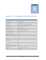
1
®
Genie II
User Manual
(Instrument Software Version v2.25)
Unit 5, Blatchford Road
Horsham
West Sussex
RH13 5QR
United Kingdom
Tel: +44 (0) 1403-274980
Fax: +44 (0) 1403-271017
www.optigene.co.uk
[email protected]
If you have any feedback or comments about the instrument please email:
[email protected]
Information in this document is subject to change without notice.
OptiGene Ltd. assumes no responsibility for any errors that may appear in this document. This document is believed
to be complete and accurate at the time of publication.
In no event shall OptiGene Ltd. be liable for incidental, multiple, or consequential damages in connection with or
arising from use of this document.
Genie® II and its design is a registered trademark of OptiGene Ltd. or its subsidiaries in the UK and other countries.
Table of Contents
To load a saved profile ................ 18
SAFETY NOTICES ................................ 3
SUPPORT ............................................ 5
How to obtain support....................... 5
Supported consumables .................... 5
BOX CONTENTS .................................. 6
SITE PREPARATION ............................ 7
How to set up Genie® II ..................... 7
Active ............................................... 20
Profile .......................................... 20
Temperature ................................ 20
Amplification ............................... 21
Anneal .......................................... 21
Results ......................................... 22
View ................................................. 22
CONNECTING TO A COMPUTER....... 25
Genie® II Software updates ............. 28
Connections ....................................... 8
GENIE® EXPLORER ........................... 30
Opening & Closing the Lids ................ 8
Main Menu ...................................... 30
Inserting Tubes .................................. 9
New.................................................. 31
Thermal Profile ............................ 32
Graph Options ............................. 35
Channels ..................................... 36
Notes ........................................... 36
Battery ............................................... 9
Battery monitor ............................... 10
Screen Brightness Control ............... 11
USER INTERFACE .............................. 12
Genie® II Welcome Screen............... 12
Main Menu ...................................... 13
Toolbox ............................................ 13
Buttons......................................... 13
Power ........................................... 14
Colours ......................................... 14
Utilities ......................................... 14
Touchscreen calibration .............. 15
Date and Time.............................. 15
Active ............................................... 37
Profile .......................................... 37
Temperature ................................ 38
Amplification ............................... 38
Amplification Rate ....................... 38
Anneal .......................................... 39
Anneal Derivative ........................ 40
Result ........................................... 40
Analysis & Graph Options ................ 42
File ................................................... 43
Service ............................................. 44
Options ............................................ 44
Run ................................................... 16
Quick Start ................................... 16
Profile Screen ............................... 16
To create a new profile ................ 17
GENIE® II TECHNICAL SPECIFICATION
......................................................... 45
Chapter
1
SAFETY NOTICES
Please read the following notices carefully before
using Genie® II.
The equipment supplied has been designed to be completely safe to use. However to avoid any
risk to the safety of the equipment, operator, or anybody in the vicinity of the equipment,
please read this chapter before unpacking and using the instrument. If there is any doubt as to
the correct use of the equipment contact the vendor.
Notices
Using the instrument in a manner not specified by OptiGene may result in
personal injury or damage to the instrument.
Always ensure that the surface on which the instrument is placed is level and
stable and will not cause the instrument to topple over. Ensure that the surface
is suitable for the weight and size of the instrument. If the instrument is
dropped it may be damaged.
The instrument should never be lifted by its covers. Always ensure that the base
or sides are used as the lifting point.
The instrument is electrically powered. Please ensure that the correct voltage
settings have been applied before applying power to the instrument. If in doubt
consult a qualified electrician. The instrument has a rating label affixed to the rear.
Please consult this if needed.
Version 1.02
3
Always disconnect the equipment before moving or removing any guards or
covers. Switch off at the mains, remove the mains plug from the wall socket and
remove the cable from the inlet socket on the rear.
While every effort has been made to protect the inside of the instrument
against splashes, the instrument carries no IP rating. If fluids are spilt on the
instrument they may cause damage and cause an electrical hazard.
If a spill occurs, remove power from the instrument. Do not touch the
instrument or any fluid flowing from it while it is connected to the mains supply.
Always follow local health and safety guidelines.
Normal safe local operating standards should be applied at all times. The warnings above are
for guidance only. Please consult the instrument supplier if there is any doubt.
Disconnection Method
Genie® II is disconnected by removal of incoming mains power source to the
unit. Following disconnection the unit should be left for a period of at least 5
minutes before any internal assemblies are removed or examined.
When in use the heating blocks and heated lids are hot, so allow to cool before
touching the surfaces.
Safe removal of fluids from Genie® II will depend on the chemistry used. This will
also require knowledge of the fluids used in the system to adhere with local health
and safety and COSHH regulations. If in doubt, consult the person responsible for the
equipment in the laboratory.
Cleaning Method
The Genie® II can be disinfected using the following procedure. This same procedure can be
used as a safety measure if this equipment is routinely exposed to bio-hazardous materials.
1. Wipe all outside surfaces of the Genie® II with a 10% bleach solution.
2. After 10 minutes wipe all the same surfaces with a 70% ethanol solution.
CAUTION: Do not allow any of the bleach or alcohol solution to enter the wells as this can
cause damage.
Version 1.02
4
Chapter
2
SUPPORT
HOW TO OBTAIN SUPPORT
For the latest services and support information go to http://www.optigene.co.uk/support.htm
IMPORTANT! When directed to do so, contact OptiGene Ltd. to schedule maintenance
or calibration of a Genie® II instrument.
IMPORTANT! If a Genie® II instrument is kept in a very cold environment, the battery
will not begin charging until the internal temperature has reached 15°C.
SUPPORTED CONSUMABLES
IMPORTANT! Genie® II uses a proprietary tube strip that maximises optical and
thermal efficiencies. Other tubes and strips will not fit.
IMPORTANT! Forcing non-supported consumables will cause damage to the
instrument and invalidate the warranty.
IMPORTANT! The shape of the tubes is such that they will only fit in one way round.
The locating pins on the block have corresponding holes in the strips.
Version 1.02
5
Chapter
Chapter
3
2
BOX CONTENTS
The following is a list of contents in the box for Genie® II:
•
Genie® II instrument
•
Power supply
•
Power lead
•
USB connection lead
•
Stylus
•
USB memory stick containing Genie® Explorer and this manual as a ‘.PDF’ file
Version 1.02
6
Chapter
Chapter
4
1
SITE PREPARATION
HOW TO SET UP GENIE® II
The laboratory bench should be level and stable. The instrument should be placed centrally on
the lab bench and the surfaces surrounding the instrument must be clear of obstructions at all
times.
Care must be taken not to unduly restrict the air at the front of the instrument and the outlet
vents at the rear. Restricting airflow may impede operation and could affect performance.
Electrical points should be close to the instrument to avoid injury from trailing wires.
It is recommended that the instrument is kept away from sinks and other wet areas. Genie® II
is an electrical instrument and care should be taken not to operate if there is a risk of water
damage.
Version 1.02
7
CONNECTIONS
Genie® II is ready to use straight out of the box without any external connections. It can be
operated standalone, taking power from its internal battery. In order to charge the battery or
to use Genie® II with a computer, some connections must be made.
Connect the power supply plug into the back of the instrument and then attach the power
cable to the supply.
Located at the rear of the instrument is an on/off power switch. When in the on position
Genie® II will power up and progress through its checks.
POWER INLET
POWER SWITCH
USB (TO PC)
OPENING & CLOSING THE LIDS
Gently lift the lids upwards. Close the lids by lowering gently.
Care must be taken to ensure that objects are not obstructing the lids when trying
to close it and under no circumstances should the lids be forced open or closed.
Version 1.02
8
INSERTING TUBES
IMPORTANT! Genie® II uses a proprietary tube strip that maximises optical and
thermal efficiencies. Other tubes and strips will not fit.
IMPORTANT! The shape of the tubes is such that they will only fit in one way round.
The locating pins on the block have corresponding holes in the strips.
BATTERY
Genie® II has an internal rechargeable battery. When Genie® II is delivered the battery should
be fully charged and ready for use.
The battery monitor is on the status bar next to the block temperature reading.
To see more details on the battery, press the battery icon and the monitor will appear as a popup in the bottom right hand corner of the screen. To remove the pop-up press on the status bar
indicator again.
Battery monitor pop-up
IMPORTANT! Genie® II’s internal battery will only charge when the instrument is
plugged into mains electricity and the instrument is switched on. Genie® II can be placed into
standby using the power button in the bottom left corner. The LED above the display will glow
brightly until the battery is fully charged. At this point Genie® II can be switched off using the
switch on the rear.
Note: If this button is pressed during a run, Genie® II will not enter standby.
When in standby, normal operation can be resumed by pressing anywhere on the screen.
Version 1.02
9
BATTERY MONITOR
The battery status can be seen but
there is no pop-up.
Here the pop-up shows that the
battery is currently charging.
Here the pop-up shows that the
battery is fully charged.
Here the pop-up shows that the
instrument is discharging.
Version 1.02
10
SCREEN BRIGHTNESS CONTROL
Next to the battery icon is the brightness control.
Touch the icon and a slider will appear on the right hand side of the screen. Move the slider to
the desired position. Press the icon again to remove the slider.
It is not recommended to set the
brightness at 100% for long periods
of time, as this will significantly
decrease battery life.
Version 1.02
11
Chapter
Chapter
5
1
USER INTERFACE
Genie® II uses a touchscreen for viewing and inputting data.
Touch the screen gently and press the appropriate keys when required. The touch screen can
be operated while wearing protective gloves or by using the stylus included with the
instrument.
IMPORTANT!
Do not use a pen or any other sharp implements to touch the screen.
GENIE® II WELCOME SCREEN
When switching on, the LED above the screen will be amber in colour. Wait for the light to
change to green, then touch the screen to access the main menu.
Version 1.02
12
MAIN MENU
To start a predefined run, touch the name of
the assay and it will begin. Alternatively,
touch ‘Other…’ to create a new profile, or
open a saved profile.
To view profiles or data from previous runs
touch the folder icon
on the status bar.
To access the toolbox touch the spanner icon
on the status bar.
IMPORTANT!
When running for the first time check that the date and time on the
status bar are correct. These can be changed by clicking on the date and time.
TOOLBOX
Pressing the spanner icon in the taskbar will load the toolbox.
BUTTONS
Set up the quick start buttons on the
main screen.
Touching ‘…’ will allow the user to
browse the saved profiles on the
instrument and assign that profile to the
corresponding quick start button on the
main screen.
To remove the buttons, untick the box
next to the profile name.
Version 1.02
13
POWER
These settings only apply when battery
powered.
Display dim time: how long the
instrument waits without input before
dimming the display.
Display dim level: the brightness level
the instrument will use after the
specified idle time.
Standby time: how long the instrument
waits before turning off the display.
COLOURS
The background colour and the default
colours of the lines on graphs can be
changed here.
Click the background button or a graph
number and then drag the cursor on the
colour chart to select a colour.
The two small coloured boxes on the
right show the colour that is currently
set (Cur.) and the default (Def.) colour.
Pressing on either will set the colour.
UTILITIES
Touchscreen: This will start the
touchscreen calibration (see below).
Date & Time: Set the time and date
within the instrument.
Update: Allows updating of the
instrument software (See Chapter 6).
Version 1.02
14
TOUCHSCREEN CALIBRATION
Touching anywhere on the screen with
the exception of ‘Test’ or ‘Skip’ will
invoke the touchscreen calibration.
To check the sensitivity of the screen
press ‘Test’. Any point pressed on the
screen will then be marked.
Calibrate the touchscreen by touching
the target points shown on the screen
(the stylus should be used for this).
It is also possible to run the touchscreen calibration when the instrument first starts. Press and
hold down on the welcome screen for 5 seconds to initiate.
DATE AND TIME
Date: click in the white box for date and
enter in the format DD/MM/YY.
Time: click in the white box for time and
enter in the format HH:MM:SS.
Press ‘Set’ to save or click the cross to
cancel.
Version 1.02
15
RUN
On Genie® II, there are two ways to start a run: either quick start, by touching one of the
predefined profiles saved on the instrument or by creating a new profile. Predefined profiles
can only be selected for quick start if they are saved anywhere on the instrument file system.
QUICK START
Up to six saved profiles can be shown
on the main screen to allow quick
starting of an assay. The six profiles
are selected from the ‘Buttons’ page in
the Toolbox.
Pressing one of buttons on the main
menu will pop-up a preview of the
profile, and allows the user to start,
edit or cancel the run.
PROFILE SCREEN
To create a new profile, press the
‘Other…’ button on the main screen.
This allows access to any predefined
profiles or creation of a new one.
Cancel to return to the main menu.
Press the tick to select a file, or
to create a new profile.
If there are many profiles, scroll down
by dragging on the window.
Version 1.02
16
TO CREATE A NEW PROFILE
Press the ‘New’ button on the profile
screen. Click the graph to adjust the
profile by touching the appropriate
temperature or time box.
Once the required changes have been
made, pressing the tick button will
accept the changes. Clicking the cross
in the top corner will cancel any
changes.
Pressing the play icon will accept the
changes and prompt the user to start
the run.
To set a thermal gradient across a
block, enter a range of temperatures in
the ‘Amplification’ temperature box.
The range of temperatures should be
entered separated by a hyphen, as
shown below.
Pressing the save icon will save the
profile. Name the profile, press the tick
button and it will be saved within the
‘PROFILE’ directory in the on-board
memory allowing it to be loaded for
future runs.
Version 1.02
17
TO LOAD A SAVED PROFILE
Pressing one of the quick start buttons
on the main menu will pop-up a
preview of the profile and give the user
the choice to start, edit or cancel the
run.
Alternatively, press the ‘Other…’ button
and a file browser will be displayed.
Choose the profile to be loaded and
press the ‘Open’ button.
A preview graph will appear, and allow
the user to start, edit or cancel the run.
Pressing ‘Edit’ will open the main profile
screen.
Changes can be made as required. To
begin the run, press the play icon.
A prompt will be displayed. Select ‘A’,
‘B’ or ‘Both’ to run or ‘Cancel’ to abort.
Version 1.02
18
WELL NAMES
To assign names to the block wells,
click on the well names area.
To change a well name, press on the
text box and type a name and
abbreviation if desired.
The ‘AB’ button will switch to the
second block.
Pressing the cross returns back to the
run screen with no changes made to
that well.
Pressing the tick button returns to the
run screen with changes saved.
If the profile is saved at this point the well names and abbreviations will also be saved as part
of the profile. The well names screen can be accessed at any time the instrument is running by
clicking on the ‘Results’ tab and clicking anywhere on the well names column.
When a run is started, the main screen
will display a preview of the run that is
active. As the run progresses, the grey
line showing the profile will turn red.
Block A will appear on the left, and
Block B on the right. If both are
started, then the preview will appear
in the middle of the page.
Touching the graph will take you to
the active screens.
Version 1.02
19
ACTIVE
Once a run is started, the software will go to the ‘Temperature’ screen initially. The other
screens can be accessed using the tabs.
PROFILE
This shows the temperature profile that is
running.
At the top of this screen, there is a text box
to edit the run description, a button to add
notes about the run and a button to save the
profile.
TEMPERATURE
This shows the current temperature of the
block as the experiment is progressing.
EXTEND
This adds 10 minutes to the current phase of
the run.
Version 1.02
20
ADVANCE
Advances to the next phase of the run
(Preheat to Amplification or Amplification to
Anneal).
STOP
The ‘Stop’ button will abort a run in progress.
A confirmation pop up box will prompt ‘Yes’
or ‘No’.
AMPLIFICATION
This shows the fluorescence data that is
being acquired during the amplification
phase of the experiment.
ANNEAL
This shows the fluorescence derivative data
that is being acquired during the anneal
phase of the experiment.
Version 1.02
21
SELECTION OF GRAPHS
Pressing the well name on either the
‘Amplification’ or the ‘Anneal’ page cycles
the state of the related curve on the graph
between normal, highlighted and off.
RESULTS
This shows the results of the experiment.
Each sample name is shown along with
amplification time and anneal temperature.
VIEW
To view previous runs press the folder icon on the status bar.
This will display a file browser
window.
All Genie® II runs are saved in the
‘LOG’ folder.
To open, click on ‘LOG’ and then tick
icon, or double press on the folder
name.
Version 1.02
22
Each run is stored in a folder by date
order: Year/Month/Day.
Each run is stored in a folder by date
order: Year/Month/Day.
Each run is stored in a folder by date
order: Year/Month/Day.
The default filename for the each run
is the instrument serial number
followed by a sequential number.
Touch on a file, a preview will appear
in the right hand pane, then touch
the tick icon to load it.
To delete a file, touch the trash can
icon.
When the file has opened, Genie® II will display the profile that was run, the temperature log,
amplification data, anneal data and the results table.
Version 1.02
23
ZOOMING FUNCTION
Zooming is available on temperature, fluorescence and anneal graphs.
To zoom in on the area of interest,
touch the plot area and drag to the
right and/or down.
To zoom out, touch on the plot area
and drag to the left and/or up.
A double press on the screen will zoom out to the full extent of the graphs.
Version 1.02
24
Chapter
Chapter
6
1
CONNECTING TO A COMPUTER
Genie® II is a standalone instrument; however, for software updates, data upload and
additional analysis, it will need to be connected to a PC running Microsoft Windows (XP, Vista
& 7).
Disclaimer: Genie® Explorer is an additional tool and should not be used for patient care or
clinical analysis.
IMPORTANT! Do not plug any Genie® instrument into the computer before installing
Genie® Explorer. Genie® Explorer can be installed from the USB drive included with any Genie®
Instrument.
Open the USB drive in ‘My Computer’.
Run the file ‘GenieInstall.msi’.
Follow the onscreen instructions.
*A prompt may appear requesting
installation of .NET Framework 4.0. This
must be installed prior to installation.
Follow the link to the Microsoft download
page.
http://www.microsoft.com/engb/download/details.aspx?id=17718
Version 1.02
25
Choose a location for the installed program.
Confirm to start the installation.
The installer will copy all necessary files to
the computer.
Version 1.02
26
Once the installation is complete, exit by
clicking ‘Close’.
A Genie® instrument can now be connected to the computer. When connected via USB and
switched on, the Genie® instrument will appear as a USB drive and will be accessible from
Genie® Explorer.
Version 1.02
27
GENIE® II SOFTWARE UPDATES
It is recommended to keep the software on Genie® II up-to-date. Upgrading may improve
performance and add new features to Genie® II.
There are two types of software on Genie® II; the firmware, and the FPGA software. The
current versions of firmware and FPGA software that are installed on Genie® II are displayed in
the bottom left hand corner of the main menu screen.
•
To download the latest firmware, visit the OptiGene website
(http://www.optigene.co.uk). Click on ‘Support’ and click on the appropriate link on
the right hand side of the page and download the ‘.zip’ file.
•
Open the ‘.zip’ file and extract the contents to a new folder. The contents of the folder
will include the latest firmware, FPGA software and this manual.
•
If Genie® II already has the latest FPGA software only the firmware will need to be
updated.
•
If both firmware and FPGA software updates are required, update the FPGA software
first, followed by the firmware.
•
If it is a firmware update, the file will be a ‘.mot’ file, whereas if it is an FPGA software
update it will be a ‘.rbf’ file.
Version 1.02
28
To install the updates, connect Genie®
II to a computer. Navigate to ‘My
Computer’ and open the Genie® II
drive. The drive is named with the
instrument serial number,
e.g. GEN2-2001. Copy and paste (or
drag) the firmware or FPGA software
files onto the Genie® II drive.
Now on Genie® II select the Toolbox,
touch the ‘Utilities’ tab and press
‘Update’. Genie® II will prompt for a file
to use for the update.
Touch on the file, and touch ‘Open’.
Genie® II will then install the updated
software. Please wait for it to finish
before trying to do anything else.
If the update was a firmware update, Genie® II will restart when completed. If an FPGA
software update was performed, Genie® II will require a manual restart by turning the
instrument off and on from the switch on the rear of the unit.
Genie® II will automatically delete the files when the update has completed.
Version 1.02
29
Chapter
7
GENIE® EXPLORER
In addition to standalone operation, Genie® instruments can be run and completely controlled
by a computer and the results data then stored and analysed. The software that supports
remote operation is called Genie® Explorer and is included on the OptiGene USB memory stick
that is included with the Genie® instrument (installation instruments are in chapter 6).
Disclaimer: Genie® Explorer is an additional tool and should not be used for patient care or
clinical analysis.
To run Genie® Explorer, double click on the icon on the desktop or run from the ‘Start Menu’.
MAIN MENU
When the program has loaded, the first screen that will be displayed is the main menu where
there are several options. ‘New’, ‘Profile’, ‘Active’, ‘File’, ‘Service’, and ‘Options’.
Version 1.02
30
GENIE® EXPLORER DISCOVERY PANEL
Any Genie® instruments that are connected to the computer will be shown
in the panel on the left side of the screen. Multiple Genie® instruments can
be connected at the same time. If any instrument is connected and not
displayed, click the scan for instruments button in the bottom left corner
and the program will attempt to connect to them.
NEW
Clicking the ‘New’ button will display the following window, which will allow a new experiment
to be set up and run on an instrument. Multiple profiles can be set up at the same time and
selected via the taskbar at the bottom of the window.
Version 1.02
31
THERMAL PROFILE
The ‘Thermal Profile’ tab allows setting of the thermal profile that is to be used and calculates
an estimated run time for the desired profile.
If activation is required for the enzyme then
tick the ‘Preheat/Activation’ checkbox and set
the required temperature and time.
Check that the ‘Isothermal’ checkbox is ticked
and then alter the temperature and time to
suit the assay conditions.
If the assay requires an anneal, check the
‘Anneal’ box and alter the start temperature,
end temperature and cooling ramp rate. This
dialogue box shows how to set an annealing
curve from high to low temperatures.
Version 1.02
32
ADVANCED BOX
The ‘Advanced’ button shows a pop-up screen showing several options, which allows changes
to be made to the instrument control parameters.
RAMP RATE
The ‘Ramp rate’ specifies how fast the heating will occur. It can be set for the three different
phases independently.
MEASURE PERIOD
The ‘Measure period’ is the interval between measurements of fluorescence and is measured
in seconds. It can be set for both the isothermal and anneal phases.
SETTLING TIME
The ‘Settling time’ is the time that the instrument will wait once it has reached the desired
annealing temperature before it starts to take readings.
LOW GAIN
This option is mainly for use if the user is running experiments with Calcein. The range of
values is between 0 and 7. Some guidelines on values are:
0 – Normal use (Default).
4 – Low gain for use with Calcein.
7 – Lowest gain.
BLOCK GRADIENT
The ‘Block Gradient’ facility enables a gradient to be set across the blocks. This is especially
useful when setting up assays for optimisation of the amplification temperature.
Version 1.02
33
Example of setting up a gradient:
Set temperature of the midpoint of the
block as the temperature of the
‘Isothermal’ stage on the Temperature
Profile screen.
Then set the temperature range for the
block, by adjusting the ‘Block Gradient’
parameter. For example, if the midpoint
temperature is set to 63.5°C, and the
gradient is set to 7°C, that will set well 1
to 60°C, well 2 to 61°C, etc. through to
67°C in well 8.
SAVE
Profiles can be saved in order to repeat experiments. Clicking the ‘Save’ button will store the
profile on the computer. The default location is set within Genie® Explorer, and can be changed
if desired. Any saved profiles from Genie® Explorer can also be copied to a Genie® instrument’s
internal memory and run directly from the instrument. Copy the saved profile to the ‘Profile’
folder on the Genie® instrument and then access it on the instrument as normal.
OPEN
Any saved profiles from either Genie® Explorer or a Genie® instrument can be run from Genie®
Explorer. Navigate to the profile file, select it and all the parameters will be loaded in.
RUN
Pressing ‘Run’ will start the experiment.
On clicking ‘Run’ this box will appear. This
allows selection of which block is being
used and also options for saving of the
run file. The default location for saving
the files is set within Genie® Explorer, and
can be changed in ‘Options’.
If the Genie® instrument only has one
block, then only block A will be
selectable.
Version 1.02
34
GRAPH OPTIONS
Clicking on ‘Graph Options’ will display the following screen.
Choose either 8 Wells (one block)
or 16 Wells (two blocks). (Genie®
II only supports 8 wells).
It is also possible to enter well
names, change plot colours, set
line styles and to select which
wells are visible on the results
display.
The tabs allow the parameters for
all graphs to be adjusted.
Click on the tabs for each graph
and alter settings as required.
For more information see section
‘Analysis and Graph Options’.
Version 1.02
35
CHANNELS
If the Genie® instrument supports multiple channels, such as the Genie® III, the ‘Channels’
button will be available.
Select which channels are to be used
in the profile by checking the
corresponding tick box.
NOTES
Clicking on the ’Notes’ button allows
experimental notes to be entered and
saved as part of the profile.
Version 1.02
36
ACTIVE
On starting a run, Genie® Explorer will display the ‘Active’ window. The status icon of the
Genie® instrument which is running will change, showing red labels for the blocks that are
active. The taskbar at the bottom allows selection of the different running profiles. If multiple
channels are being used, each channel will show as a different tab.
There are several tabs available to display the thermal profile and measured readings from the
run, i.e. ‘Profile’, ‘Temperature’, ‘Amplification’,’Amplification Rate’, ‘Anneal’,’Anneal
Derivative’ and ‘Result’.
PROFILE
The ‘Profile’ screen shows the run
profile settings.
Version 1.02
37
TEMPERATURE
The ‘Temperature’ screen
displays the measured
temperatures of the blocks and
the heated lids plotted against
time.
AMPLIFICATION
The ‘Amplification’ screen
displays the fluorescence
measurements for each well
made during the Amplification
phase plotted against time.
AMPLIFICATION RATE
‘Isothermal Ratio’ shows the
amplification take off time
during the Amplification
phase.
Isothermal Ratio peak time is
similar to the Ct or Cq values
in qPCR assays.
Genie® Explorer can detect the trace peaks and report them automatically. To access the graph
options click ‘Settings’ on the graph and a side panel will appear.
Version 1.02
38
Select the ‘Peak detection’ option
(‘None’, ‘Simple’ or ‘Full’) and check the
default peak criteria.
The peak threshold (minimum value of
peak) can be adjusted to ensure that all
valid peaks are identified while others
are not.
ANNEAL
The ‘Anneal’ tab shows the plot of
the fluorescence measurements for
each well made during the Anneal
phase plotted against temperature.
Version 1.02
39
ANNEAL DERIVATIVE
The ‘Anneal Derivative’ tab
shows the plot of the derivative
of fluorescence for each well
made during the Anneal phase
plotted against temperature.
Select the ‘Peak detection’
option (‘None’, ‘Simple’ or
‘Full’) and check the default
peak criteria.
The peak threshold (minimum
value of peak) can be adjusted
to ensure that all valid peaks
are identified while others are
not.
RESULT
This page shows the results in a
tabular format and displays the
Amplification Rate peak times
and Anneal Derivative peak
temperatures.
Version 1.02
40
ADDITIONAL TOOLS
From left to right, the buttons are:
Save: The results will be saved to a ‘.gen’ file,
for subsequent access from either the
instrument or software.
Save Profile: The profile currently being run
will be saved.
Stop: This will stop the run in progress.
Skip: To advance to the next phase, press the
‘Skip’ button.
Extend: If more time is required on the
current phase press the ‘Extend’ button and
the run will extend by 10 minutes. A
confirmation box will pop up every time
‘Extend’ is pressed and the run profile will be
updated to show the new time.
The buttons below the graphs can be used to
zoom in and out of the graph in different
directions. The ‘Reset’ button will return the
graph to its original state.
From left to right, the buttons are:
‘Save to Text’ will save the raw data to a
comma separated ‘.txt’ file for import into a
spreadsheet application, such as Microsoft
Excel.
‘Save to Image’ will save the current graph to
a ‘.jpg’ file.
‘Report’ will display all of the results of the
experiment in an organised report form,
which can be printed or saved.
These buttons allow the data to be saved in
different formats.
Version 1.02
41
ANALYSIS & GRAPH OPTIONS
Click the ‘Settings’ button on a graph and Genie® Explorer will display the graph options for
that graph. From this window several aspects of the graphical information can be modified.
SMOOTHING
Smoothing can be applied to all of the graphs.
Drag the slider or change the ‘Points’ value to
set the number of readings that are averaged
to create a data point on the graph.
NORMALISATION
Normalisation allows all the fluorescent
signals to have their background level
removed, calculated over a specified period
of time.
Select by ticking the ‘Normalisation’
checkbox and setting the start and end
times for calculating the background level
e.g. 60 seconds to 180 seconds.
This screenshot shows data that has not
been normalised; the initial signal levels are
different for each well.
With normalisation, the levels come
together and allow for easier analysis.
Version 1.02
42
PEAK DETECTION
Simple: The software looks at the plot and
assigns the peak to the highest plotted
point that is above the ‘Threshold’ value.
Multiple peaks can be detected.
Full: The software performs more
complicated analysis of peaks above the
‘Threshold’ value. Multiple peaks can be
detected.
Invert: inverts the graph
FILE
To view previously run data go to the main menu and click the ‘File’ button. Then click on either
a Genie® instrument or ‘PC’ to browse for a run file.
Files are saved as ‘.gen’ files by default in the folders specified in Genie® Explorer ‘Options’, or
in the Log folder on a Genie® instrument. The run file is encrypted.
The requested file will be loaded
and analysis of the data can be
performed. The file will load and
be displayed in the same way as
an active run.
Version 1.02
43
SERVICE
Clicking the ‘Service’ button on the main menu will produce the following screen.
From here, it is possible to change
the date and time of the
instrument’s clock, and update
firmware or FPGA code on the
instrument (instead of using the drag
& drop method described in the
instrument user manual).
OPTIONS
The ‘Options’ button allows the default locations of files to be set.
Profile: Default location for saving
profiles.
Data: Default location for saving run files.
Default Profile File: Sets a default profile
to be used when a new run is started. To
reset back to the program defaults, click
‘Reset Default Profile’.
Click ‘Save’ to save changes to the default
locations.
Version 1.02
44
Chapter
8
GENIE® II TECHNICAL SPECIFICATION
Sample Number
16 wells (2x8 strips)
Sample Volume
10 µl to 150 µl
Touchscreen
High-brightness TFT / LCD module (800x480)
Heater technology
Ceramic substrate with resistive coating
Cooling method
Forced convection
Temperature sensor
High-precision thermistor
Temperature control type
Multi-zone independent digital PID
Temperature control range
ambient - 100°C
Temperature accuracy
±0.1°C
Temperature uniformity across
block
±0.2°C
Temperature gradient
Programmable up to 8°C
Optics source
470 nm LED with high-quality interference filter 40 nm band
pass
Detection optics
Photodiode with high-quality interference filter 510 nm long
pass
Operating temperature
10°C - 40°C
Approvals
CE
Power consumption (maximum)
150W
Dimensions
20cm (H) X 21cm (D) X 30cm (W)
Weight
2kg / 4.4 lb
Version 1.02
45
Unit 5, Blatchford Road
Horsham
West Sussex
RH13 5QR
United Kingdom
Tel: +44 (0) 1403-274980
Fax: +44 (0) 1403-271017
www.optigene.co.uk
[email protected]
If you have any feedback or comments about the instrument please email:
[email protected]
Information in this document is subject to change without notice.
OptiGene Ltd. assumes no responsibility for any errors that may appear in this document.
This document is believed to be complete and accurate at the time of publication.
In no event shall OptiGene Ltd. be liable for incidental, multiple, or consequential damages in connection
with or arising from use of this document.
Genie® II and its design is a registered trademark of OptiGene Ltd. or its subsidiaries in the UK and other
countries.
Version
V1.00
V1.01
V1.02
Date
10/07/14
01/04/15
17/09/15
Changes
Initial Release
Added disclaimer about Genie Explorer.
Added instrument cleaning guidelines
and feedback email address.
Approved
SUL
SUL
SUL
Version 1.02
46