1
Ell=111111111111111111111111111111
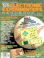
POPULAR ELECTRONICS
1978
HANDBOOK.
$,.gs
INCLUDING HOBBYIST MICROCOMPUTER SECTION
Digital Logic Probe...
Auto Ignition Timing
Light ... Photo Enlarger
Controller ... Single -IC
Weather Receiver...
Minivolts Meter
... Night Cycling
Safety Lights...
A
HO Train Speed
Control ... Low-Cost
Metal Detector...
Solid-State TV
Camera ... Audio
Compander ... AND
MORE!
Complete Home
Computer Buying
Directory
A PER
.4;
14024 14268
Electronics Exp. Hdbk.
úi
vide
includes
ícs chip.
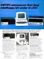
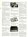
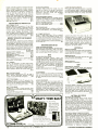
SWTPC announces first dual
minifloppy kit under $1,000
MINLOPPY
WT&- DISK SYSTEM
Now SWTPC offers complete best -buy computer system with $995
dual minifloppy, $540 video terminal/ monito-, $395 4K computer.
$995 MF -68 Dual Minifloppy
You need dual drives to get full benefits
from a minifloppy. So we waited :o offer a
flocpy until we cou d give you a Dependable dual system at :he right price-.
The MF -68 is a complete top- puality
minifloppy for your SWTPC Computer. The
kit has controller, cnassis cover. pcwer
supply, cables, assembly instructions :wo
hiçhly reliable Shugart dives, and a
diskette with the Floppy Disk OpErat rg
System (FDOS) and disk 3ASIC .A floppy
is no better than its operating sys -em, and
the MF -68 has one of the best ava lame.)
An optional $850 lvF -6X kit expards tie
system to four drives.
$500 Terminal/1fonitor
The CT-64 terminal kt offers theme
premium features: 64- cha-acter ires,
Lpper /lower case leters, switch.able c Dntrol character klir:inc, wo-d highlighting,
full curso- cont-ol 110 -12CC Baud serial
interface, and many others. SepErately
the CT-6z is $3_5 the 12 MHz C - -VM
monitor $175.
$250 for the PF -40 _ine P inter
$7950 for f.0 -30 Cassette Inferec e
Addlional 41. memory boards at S 0]
Addlional 84 memory boards at 525]
Exp. Date
Or EAC #
Enclosed Is:
990 for the fu I system shown ar ve
(MF -68 Miniflopjy, CT-64 Terminal with
CT-VM Monitor).
$995 for the Ducl Minifloppy
$325 for the CT-64 Terrrinal
$175 for the CT-WM Mor itor
$395 for the 4K 6800 Computer
$1
Or YIC
#
Exp.
CIRCLE
Dite
Address
Name
C ty
Zp
S-ate
NO
23
Ch
IIEE
NFORMA-ION
Cf.RJ
$395 4K 6800 Computer
The SWTPC 6800 comes complete with
4K memory, serial interface, power supply,
chassis, famous Motoro a MIKBUG®
mini -operating system it read -only
memory (ROM), and the most complete
documentation with any computer kit. Our
growing software library includes 4K and
8K BASIC (cassettes $4 95 and $9.95;
paper tape $10.00 and $20.00). Extra
memory, $100/4K or $250/8K.
Other SWTPC peripherals include
$250 PR -40 Alphanumeric Line Printer
(40 characters /line, 5 x 7 dot matrix,
75 line /minute speed, c3rnpatible with
our 6800 computer and MITS /IMSAI);
$79.50 AC -30 Cassette Interface System
(writes /reads Kansas C 7/ standard tapes,
controls two recorders, Lsable with other
computers); and other peripherals now
and to come.
Sou hwest Technical
Products Corp.
219 W. Rhapsody, San Antonio, Texas 78216
London: Southwest Technical Products Co., Ltd.
Tokyo: Southwest Technical Products Corp. /Japan
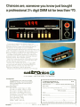
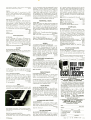
Chances are, someone you know just bought
a professional 31/2 digit DMM kit for less than $70.
Thousands of people have already bought the
Sabtronics Model 2000 ... for two main reasons. First, its
incredible accuracy, range and professional features.
And second, the incredibly low price of $69.95.
People everywhere appreciate this bench /portable multi meter. They depend on its basic DCV accuracy of 0.1% ±1
digit, its readings to ±1999 and its five functions giving
28 ranges, overload protection and 100% overrange.
The 2000 is automatically appealing to hobbyist and
professional alike. With automatic overrange indication,
automatic polarity, even automatic zeroing.
Best of all, it's easy to assemble. All the parts you'll need,
including the high- impact case, come right along with
the clear, step -by -step instructions.
The result is a professional quality 31/2 digit DMM
that you could have paid a lot more than $69.95 for ..
possibly receiving a lot less. But this one's from
Sabtronics, specialists in digital technology.
Maybe you should order yours before you turn the page.
Made in U.S.A.
sabtris
INTERNATIONAL
P.O.
Box
64683
Dallas. Texas 75206
GUARANTEE:
Our guarantee to you; examine the 2000
DMM kit for 10 days. If you're not satisfied,
return it unassembled for a full refund of
purchase price.
(2141369-7310
r
To: Sabtronics International, Inc.
P.O. Box 64683, Dallas, TX 75206
Please send me
EH78
Sabtronics Model 2000 DMM kit(s) at
subtotal
$69.95 each.
SPECIFICATIONS:
DC volts in 5 ranges:100AV to 1000V
AC volts in 5 ranges: 100µV to 1000V
DC current in 6 ranges: 100nA to 2A
AC current in 6 ranges: 100nA to 2A
Resistance: 0.1f2 to 20MS2 in 6 ranges
AC frequency response: 40Hz to 50KHz
9mm (.36 ") LED display
Input impedance: 10M0
Size: 8 "W x 6.5 "D x 3 "H
(203W x 165D x 76H mm)
Shipping and handling. $5.00 per unit*
subtotal
Texas Residents Add Sales Tax
TOTAL enclosed
Name
Street Address
City
Zip
State
*USA only Canada $6.50 All other countries, $1000 (surface mail)
6..
Power requirements: 4 "C" cells (not included)
1978 Edition
CIRCLE
NO
22
ON
FREE
INFORMATION
CARD
OTT 7400N TTL
5574005w
.16
SN7401N
16
5574025
or
SN7403N
16
SN7404N
SN7405N
18
5574065
5574075
20
29
SN7408N
25
S574095
25
SN7410N
SN7411N
SN7412N
SN7413N
18
54741431
70
SN7416N
35
35
SN7459A
5N7460N
SN7470N
SN7472N
SN7473N
SN7474N
SN7475N
5N7476N
SN7479N
SN7480N
SN7482N
SN7483N
5N7485N
53174865
SN7488N
24
30
33
45
5N74154N
SN74155N
00
99
39
37
32
5N741565
sN741575
99
99
50
SN74160N
SN74161N
32
55741634
5.00
SN74164N
SN74165N
50
70
89
39
49
45
33
.49
SN74935
49
37
SN7494N
SN7495N
SN7496N
SN7497N
79
5574255
5574265
29
29
SN7427N
37
42
SN7439N
SN7440N
SN7441N
5N7442N
25
SN74100N
SN74107N
SN74121N
SN74122N
SN74123N
SN74125N
15
SN74126N
89
59
SN74435
75
9474449
75
75
5N74132N
SN74136N
SN74141N
SN74142N
SN74143N
5N74144N
55742911
55174305
26
SN7432N
SN7437N
31
27
27
51174389
sN7445N
SN7446N
5N74474
81
69
SN7448N
SN7450N
93174519
SN7453N
SN7454N
10
1
25
2 10
5474172N
8 95
SN74184N
SN74185N
4.00
5974186N
SN74167N
1.00
39
99
T231 While
95
1.95
TOSS
55741925
95741935
89
09
SN74194N
95
1.15
SN741954
SN74196N
SN74197N
SN74198N
79
.89
SN74367N
26
SN74148N
27
5N74150N
S474151N
SN74153N
2.00
1.D0
444444Ií $22.95
wwreIM $25.95
CMOS
25
25
02
25
:306
50
2
9o7
C0a040
004042
CD4044
CD4046
004047
054049
CD4050
C04051
14j
89
1.25
25
^09
59
:20
59
25
25
-J13
4¡
L4016
1
75
1.25
75
1
75
Channel
-
5.59
90
0811
-
79
1
6.00
0812
00
75
6
F
4022
Red
65
'C22
Green
4
9722
8C22
s5L -22
Velo.
25
25
004070
95
50
CD4071
45
CD4025
75
C04026
C04027
00402B
004029
005030
S3 95
004001
CD4508
C04511
004515
C04516
004520
610,4566
001022
004023
004024
1
1
69
65
1
2
90
65
C04035
85
1
LM3u0H
LM301H
LM301CN
LM302H
LM304H
LM305H
LM307CN
LM308H
1.00
LM377N
4
00
I
39
LM320K-5.2
LM320K-12
LM320K-15
LM320T-5
LM320T-5 2
LM320T-8
I.79
1.1430655
1.79
8.00
LM3900N
LL439054
LM3909
NE531H
3.00
LM5556N
6.00
6.00
MC55585
LM7525N
LM75355
80386
LM75450
10
6 00
90
NE536T
NE540L
50
NE550N
79
_50
5E555V
NE5608
39
30
5.00
35
35
NE5618
5.00
75451CN
NE562B
35
NE56531
5.06
1.25
15452CN
75453CN
35
75
NE565N
75
75454CN
NE567H
1.25
1.95
75491CN
75
75
LM320T-15
LM320T-18
LM320T-2a
LM323K-5
75
3343245
LM339N
80
LM3a0K-5
LM340K-6
LM340K-8
LM340K-12
LM340K-15
LM340K-10
LM340K24
LM340T-5
LM340T-6
LM340T-8
95
95
95
95
LM340T-12
LM34UT-15
75
LM340T-18
75
LM340T-24
LM35oN
LM351CN
75
00
65
75
95
70
95
75
75
29
39
55
55
CA30a6
CA3053
D0
093059
043060
CAï080
1
1
90
1
25
39
39
79
CA3053
19
043102
40
85
03123
06130
20
1
50
95
15
I
85
1
75
RÚ194
75
95
954195
25
-LS5
64
/5L5175
741ti66
25
1
I
1
55
89
55
2 25
2
I
7
'44S93
39
39
:
,10
.
4 DIgt1
51145314
6
MM5316
4
M53'8
Outputs
8CD outputs
BCD Outputs
12 or 24 Hour
Alarm
PPC
Digit
00
I
Reset PIN
12 or 24 Hour
5
1
0,0pul
PPS
50 or 60 01
7,7íM
i
6
-95
Corn
operating menai
Bads
use
DL
747
9
111
550
0
DI
M
500
2
50
15
491
50
at
Dip Package
as
10
8
a
xld
I
DO
1
00
Multi -Digit
ore
7910
.99
79
4
Digit
99
09
5
Digit
1.19
.99
-
TYPE
4
S
44
60
59
S
14
16 pin
6.8
8.2
6,1
00
4,1 00
154148
50
75
20009
400/m
19m
1N4154
35
10m
45:1
12,1
00
8'100
411.00
1N4305
154734
1N4735
75
2501
20,1
DO
00
411.00
411
1135234
6 2
1N5235
155236
15456
14458
194858
144001
1N4002
464003
144004
6 8
500m
500m
500m
40m
28
28
25
150
7m
180
AMP
AMP
AMP
AMP
I
100 PIV
200 PIV
1
1
400 Plu
1
0360
038M
262328
M04 980 -1
28
iw
1*
28
28
6 B
154738
B2
I
60 .00
194742
12
10
00
6/1 00
12/1 00
12 :1 00
144744
1N1463
15
1w
1311184
50 PIV
400 PIV
35 AMP
35 AMP
461105
164186
141188
150 PIV 35 AMP
200 PIV 35 AMP
400 PIS 35 MAP
154 @ 400V
SCR
354 @ 2005
6A @ 2005
SCR
28
28
28
60
1
170
1
50
1
80
3
00
50
FW BRIDGE REC
124
PM BRIDGE ABC
Co.
0
rs
106
200V
33,
m11569
12221
5 222A
52369
523094
42194
579U64
431m
5290.4
5$1 00
195
211
w30ss
M4F3055
$
89
Si
100
r4/f2955
$t '5
;
S1
3395 6
2
OC
1w
294 123
N5d46
7HSOB'
5$'
MOU
1
78,178
1005139
145109
365951
MOSE116Ca
1N5412
071
ISt
1051
nn
.089
$1 00
4
294014
4s
5$1 00
00
65
$1 00
5 $1 00
4$1 00
241901
243904
743905
2,13906
14401,
14,
I44409
$
241'25
Oo
411 00
e4440,
?4u02
.103
53100
53100
261 74
53100
P.250
W
$SOI
23705
3706
95
1
411 00
00
431 00
.13569
243'04
52925
95
1
124 @ 50V
TRANSISTORS
VIS
n
SI 95
SCR
1
45
10 Mn
CO
1w
1314736
12,4.00
121 00
}29
WIRE WRAP SOCKETS (GOLO) LEVEL h3
5.6
CO
í0r100
SCR AND FW BRIDGE RECTIFIERS
99
30
35
38
1333600
28
6/1
1971
50 PIV
PRICE
10,1 00
10,1 00
154006
154007
28
5
W
600 Phi I AMP
800 PIV 1 AMP
1000 PIV 1 AMP
00
5000
7
VOLTS
1144005
471
MOO 980 3
52
14
62
TYPE
4/1 00
400m
400m
400m
5 6
SOLDERTAIL STANDARD (GOLD)
p
5 6
PRICE
$2.95
RECTIFIERS
400mm
155232
SOLDERTAIL STANDARD (TIN)
5T,
1
15
_.
as
5
-
DIODES
1496513
24
37
W
3 3
514.95
40.
-
400m
400m
LOW PROFILE (TIN) SOCKETS
S
VOLTS
15746
197544
15752
14753
14754
Includes AY- 3-8500 -1 Chip and 2.010 mhz crystal
(2.010 crystal -51.95 ea /AV-3- 8500-1 chip -$13.95 ea.)
1
P1n
ZENERS
131959
3 Digit
minn
4
-
TV GAME CHIP SET
d
ordo
-
1,110
Common Cathode Red
3 -5 volts G, 5 mils /second
z Dig it $
7 segment Monolithic
22
22 pin
6On
Oalnode
Va" ht.
18 p
Pm
Annr
e.
95
99
99
99
1
Cchcrle
DATA HANDBOOKS
out a Function,! Description
ALL THREE HANDBOOKS $6.95
Linen
99
400
600
HP 5082 -7300 Series
0
16 p
1
300
300
CallOur
8.00
20.00
6.00
Pin out a oesr:r,prion of 5400 7400 iCS $2.95
CMOS Pin out 6 Description 01 4000 Se.,es ICS $2.95
5
1
p
9
t
$99.95
Adapter BC -28
Rechangeable BaOedes 8P -28
Carrying Case LC -28
AC
with test
s
7400
300
400
Anode
24: ^
Bor
35 pit
$
`
31
ni
Ir,
$2 00
00
39
pin
CAPACITOR
4,
16 pin
CORNER
IO VOLT CERAMIC
DISC CAPACITORS
50 PCS. RESISTOR ASSORTMENTS
ASST.
1
ASST.
2
5
15 OHM
18 OHM
i .150
39 (IHM
4'
60 OHM
11 OHM
100 OHM
120 OHM
150 OHM
180 OHM
220 OHM
2'O OHM
330 OHM
3901 OHM
OHM
680 OHM
820 IIHNA
-
ea
5 ea.
514
479 OHM
ASST.
3
ASST. 4
5
ASST.
5 ea
51-0
is
5 ea.
ea-
ASST. 6
5
1
391
4'x
5
6K
685
101,
I.k
1
ASST. 7
5
130k
IM
ea
?
2M
155
33k
69K
270K
3304
473k
560K
560K
820K
PM
l AM
'
511/1
3
SM
1
8M
Spec She6te
U.S. Fends Only
5%
50 PCS
WATT
5
1/4 WATT 5%
1/4 WATT
1/4
5M
-7 (350 PCS.)
25e
-
FREE
05
p
05
p
05
05
05
p
p
0101
1049 50-100
10 -49
50.100
03
001PF
05
04
04
03
00470F
05
04
035
035
04
03
010i
05
04
035
05
04
05
04
09
075
13
II
08
21
17
27
23
17
27
33
1901.101 CAPACITORS
5/355
30
26
22
04
1
03
0223r1
06
03
0470F
06
035
IPF
12
04
100 VOLT MYLAR FILM CAPACITORS
04
04
12
to
07
022m1
12
10
07
047mí
12
10
07
I mf
IO
IO
D7
22ml
.11359
151355
28
28
23
23
17
50 PCS
28
23
17
50 PCS.
22/35V
33/35V
47/35V
68/355
50 PCS
Send 35e Stamp for 1977A Catalog
1021 -A HOWARD AVE.. SAN CARLOS. CA. 94070
PHONE ORDERS WELCOME
(415) 592 -8097
All Advertised PrIe.. Good Thru October
ON
22 0
001mí
0022
0047mí
50 PCS
$10.95 ea.
ELECTRONICS
11
5'.
WATT 5°,.
ames
NO
05
420% DIPPED TANTALUMS
Dealer Intimation A4allable
Add 8% Sales Tao
5'.
50 POS
10 p
47
100
220
470
2 2M
4 7M
1
50 Pos
475
2204
I
WATT 0%
1/4 WATT
1205
1805
Includes Resistor Assortments
--
,
185
39k
1005
824
Ill
1.9
PER ASST.
1/4 WAIT 5'a
-k
505
ea.
154
.
72K
1505
OHM
BK
Irk
Itx
5
$1.75
011M
CIRCLE
2
710
5 17
95
95
5
38174
SOLDERTAIL
4.95
4 95
Commun
Cmllmon
Cuminnn
-o n um
vols
S9 95
4
Common Anode Rol
01741
0O
pin
14 pin
71t
MAN 4740
voltage
n FOrward
1
CLOCK CHIPS
D%il
Model2800
HT
00704
4
meg ohm
0 -10
94'o44".2-
Size
uL33e
25
1
e 16 mA
d15138
6
Resistance
S
6
541,00
orimo.
1_5í71m4
overange reaping
OC Voltage. -0- rOOOuIAC Volage 0.10005
Fret Response. 50400 HZ/DC -AC Current 0- 1000mA
x116
Flat
5t
,
Rea
0' ntgh LEO Display
Sula Zeroing
ohm resolution
1
Rana.:
INFRA-RED LED
ORO
MAN
5
.8" Display
and IO min
0
4i513E
6 01917, BCD
MV50
POLARITY
1ytrcal segment current
8
-4LS13.
MM5309
MM5311
1045312
0556
100
3817 avaiiaSie
D
74LSII:
3,
4'51
3/5
8094 except cotan
California Realdemo
74L5109
59
451
0:ange
Clear
4
55 00 each)
$5.00 Minimum Order
74LS10'
29
0r
IC
ASST. 8R
70 1S95
74LS96
39
578
:.32
55
vello.
90556
or AC operation
1Va. 0
Accuracy 1% Iyrisai
DC
S1
ala.
350
tor one witn 3817
1.95
LS92
x0556
0,mm00
4110
-
Digit
25
95
SI
4:51
300
LOO
1.95
/alc9Fi
29
3 /2
.39
CA3140
CA3600
7415162
-
B5
85
75
4 51
5 81
Mus 3640
400
Anode. le
0.r node e
25
90
7405'63
Anode green
25 mA
25
043091
6,
-
49
39
ì565
e
yen.
4011,1
MAXIMUM FORWARD
CURRENT
30
35
60
7,575
.
10 Di
00
i,,een
DI,I0
LOO
)
Anode i;
EA.
24 pro
DO
44.556
295
187
.node
0
18 pin
C0.3089
741.515
-4L5157
cam
6508000
15
50
.0551
Black
e 10 meg input impendence
u Si
tas,
...goat 392
Common Anode -,63
common Cathode
300
125
48
CA3083
C43086
:4L5151
-
56
35
30
Orange
51
Anode renom
(Lehode 4/911/19,w
Common Annd- oianu
$4.95
B9
CA1082
49
n
SPECIAL
89
39
74554
7311-10ae
49
39
39
veno.
60111
-
$3.45 ea.
00014aá Protected
4 St
40,111
Blue
New
31/2 -Digit Portable DMM
10 S1
iba
-
WD -30
-
dia
Green
4
TYPE
T
n
4.95
CA3081
7405139
1
1
FRONT VIEW
75
25
85
00
190
Rea
0711
10000 $15.00
Red - Green
-
50 ft. roll 30 AWG KYNAR wire wrap wire
Cuts wire to desired length
Specify
Blue -Yellow- White-Red
Strips 1" of insulation
Banery
4:111
5 5'
-
White - Yellow
WIRE DISPENSER
Blackjack (, or 2 plasters)
Spitfire (1 or 2 players)
Drag strip (1 or 2 players)
Maze (2 payers)
0820
0822
Baseball (2 players)
41111
4.51
Mea,
-
SPECIFY COLOR
30 AWG
100fí $2.95
50tt. $1.95
Inv,
HT
Commun
Common
Lommnn
nommon
Common
Common
Common
55
1
Orange
1222
50
79
5:6
29
69
95
69
I
109101
200
NEW. 25 Pin Version won colon & am/pm mdicaior
Cano 4015 a n osi one
2 95
79
LM141451
56
29
79
74LS00 TTL
D2
6 95
RCA LINEA
043035
043039
2.95
Croc
-
FCS 8000A
39
1
4
185
151.47479
LM1340N
LM1351N
Com
MAN 3020
LM747H
1
'I
65
95
1
50526
tommnn Anode
5x 001 Mani,
1
MAN d
MAN '4
MAN 82
50
56
1
491
-
-
WIRE WRAP WIRE
25 ft. min. 51.25
-- -
DISPLAY LEDS
MAN 1G
MAN 77
MAN 53
75
2
1M741049
L511305N
LM1307N
75
00
25
60
3
7549404
CA3013
C43073
35
35
MAN
MAN
MAN
3 25
3
4 S1
POLARITY
MAN:
3 25
75492CN
29
29
100
LM748H
LM748N
LM1303N
LM1304N
75
.15
1
LM739N
LM741CH
LM741CN
95
38
45
LM73314
95
15
I.50
5E567V
LM703CN
LM709H
LM709N
LM710N
LM711N
LM723H
LM723H
75
.7.1,
1
NE566CN
75
LM320T12
-7?
105
290
1
MAN
15
2
Hen
Green
707
TYPE
4 DO
LM1496N
LM15565
LM1812N
LM21114
LM2901N
LM3053
I.15
hl
290
LM1458C
99
100
LM309K
LM310CN
LM311H
LM311N
LM317K
LM318CN
LM319N
LM320K-5
25
x45.'14
60526
IC526
S1
5:6
MAN 84
LM381N
LM3825
5E501e
NE5104
1M30331
1
Spacewar (2 players)
Magic Numbers (computer
185- SIC
1051
8 4" lengths
3
2
1
WIRE WRAP TOOL WSU -30
WRAP
STRIP
UNWRAP -$5.95
and spare
22
4
325
LM308CN
00
2.75
0437313
00
15
3
M04044
MC14016
LM3709
1
1
74[193
:40195
5D
3 00
35
75
35
50
6 50
2.70
LM380N
19380061
1
74[1.3
45
35
95
2 15
2 50
45
LINEAR
BD
740305
740426
740739
74074
74C90N
740959
7401076
0813
0814
0819
DISCRETE LEDS
S1
.20e' dia
65
6 75
75
50209
75
74C151
740154
740451
74C160
7aC161
740163
740164
2
4
65
325
1
4'51
IMPOK4
7402031
95
95
2
Orange
50
9 95
55
1.49
35
4S1
55
CD4059
C04060
CD4066
C04069
1
CD4019
CD4020
Green
39
79
79
004053
56
C0401;
10 SI
Red
--
0815
0818
$17.95 ea.
41.11.
125' dia.
X0709
40209
60209
-
additional cartridges
Tic -Tac- Toe /Shooting Gallery
Ouadra- doodle /Doodle/
Desert Foe/Shooting Gallery
4C00N
2.75
2
-
75
1
74002N
740045
740106
2 51
I
Speed Option
Automatic time and storekeeping
Battery-free AC operation
Dual controls with 8 -way action
Built -in Pro Hockey and Tennis games
Easy hook -up on any B/W or Color TV
Factory warranty
$159.95
WK -2 -W
UNWRAP
pre- stripped wire.
LCD
90
45
2
50 pcs. each
w/bneelei 534.96
TC436 4e11ow
STRIP
Tool for 30 AWG Wue
Roll of 50 Ft. White or Blue 30 AWG Wire
Freeze Action
20% Discount for 100 Combined 7400'5
n4000
WRAP
wlbrKIM 429.45
10431 White
LED
-
WIRE -WRAP KIT
tom
25
1
94741995
5N74200N
5N74279N
SN74251N
SN74284N
5574285N
Yellow
Battery Operated (Size C)
Weighs ONLY 11 Ounces
Wraps 30 AWG Wire onto
Standard DIP Sockets (.025 inch)
Complete with built -in bit and sleeve
$34.95
6 00
.60
.60
15
HOBBY -WRAP TOOL -BW -630
Men's 8 Ladies
2.20
15.00
1.19
2 35
WIRE WRAP CENTER
1
2 49
3.95
1
522.95
LEO
.99
.90
90
SN74190N
SN74191N
4.50
4.50
,
rnreIt
YIlow
1.25
54741884
4.00
Whf r/bneIt á14.94
T249
T246
50
1
50
39
39
SN74147N
20
1
S474170N
5474182N
79
27
10
5.50
SN7a177N
SN74180N
SN74181N
79
89
9574145N
99
SN74176N
75
49
1
99
1
-
Watches
Solid State
Displays hour, minute,
second, month 8 day
Free set of replacement
batteries
Choose LED or LCD styles
One year factory warranty
25
1
SN74173N
5N74174N
9N74175N
3 50
2
1
55741664
55741675
98
S574895
21
5N7421N
SN7422N
SN7423N
22
45
SN7490N
SN7491N
SN7a92N
5574175
5574205
-
Timeband bi,,s//m
25
INFORMATION
CARD
1
01355
28
2B
3
4
01505
9/505
7/255
10025V
100505
22125V
23
17
17
1
15
13
10
16
14
11
13
10
16
14
12
15
13
16
17
15
21
27
22
31
27
4.7125V
32
28
22
23
6.825V
1025V
36
40
31
47/255
15
13
IO
47150V
31
25
29
40
16
ta
11
15
.13
10
16
14
11
10
0/165
1.0/25V
I.0050V
16
14
14
14
12
4 71165
15
13
10
15
12
4
7/25V
15
13
16
14
11
.14
12
.09
15
13
10
221505
24
20
18
47/255
47/505
100/255
100/504
19
17
15
25
13
2.2/25V
3.3/25V
17
35
28
23
15/25V
17
63
.50
28
23
MINIATURE ALUMINUM ELECTROLYTIC CAPACITORS
Á41e1 Lead
Ra4141 Leed
47509
1
23
17
-9
21
49
1
4.7/505
10/165
101250
10
10/505
16
14
12
472505
19
100116V
24
19
21
15
14
at
25
38
1001259
24
20
18
33
29
27
100
/505
35
30
-55
50
62
45
55
220116V
23
28
16
470/25V
o
27
25
24
35
20
30
220125V
220150V
32
28
45
470/25V
1000/16V
22001165
70
1B
28
ELECTRONIC EXPERIMENTER'S HANDBOOK
POPULAR ELECTRONICS
1978 ELECTRONIC
EXPERIMENTER'S
IIANDDDDK
SOLID STATE COMPONENTS CHART
BATTER -UP!
5
James
Barbarello
7
J.R. Laughlin
Robert D. Pascoe
14
Craig Anderton
Mitchell Waite
24
28
Richard
May
32
Terry A. Williamson
Charles R. Clinkenbeard
Joseph Giannelli
38
39
40
Joe A. Rolf
John F. Hollabaugh
Anthony Caristi
Herb Cohen
43
45
47
50
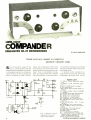
Robert C. Frostholm and Roger Lundegard
56
Carl C. Drumeller
Michael S. Robbins
George A. Ellson
Martin Meyer
Joseph E. Taylor
L. George Lawrence
61
Robert D. Pascoe
John T. Bailey
Franklin C. Willoughby
Les Solomon
Terry Walker, Harry Garland & Roger Melen
75
77
80
82
87
Martin Meyer
92
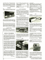
J.
A home electronic baseball game of skill and quick reactions.
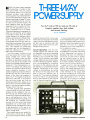
THREE -WAY POWER SUPPLY
HOW TO PROGRAM READ -ONLY MEMORIES
20
Experimenter's guide to programmable ROM's.
LOW -COST COMPANDER
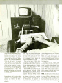
BUILD A MUSCLE FEEDBACK MONITOR
New biofeedback technique helps to reduce tensions.
IC DIGITAL LOGIC MEMORY PROBE
P.
TWO PROJECTS ADD SAFETY TO NIGHT BIKING
ALTERNATELY FLASHING TAILLIGHTS
"ALWAYS -ON" BIKE LIGHTS
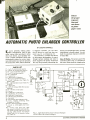
AUTOMATIC PHOTO ENLARGER CONTROLLER
Selects proper exposure time and cuts down on photo paper waste.
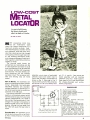
LOW -COST METAL DETECTOR
BUILD THE MINIVOLTER
AN IGNITION TIMING LIGHT FOR IMPROVING GAS ECONOMY
HOW PHASE -LOCKED LOOPS WORK
Theory and applications of a circuit revitalized by IC technology.
"TUG -OF -WAR"
An electronic game project to challenge your reflexes.
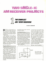
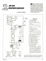
TWO SINGLE -IC AM RECEIVER PROJECTS
1
THE SIMPLEST AM /WWV RECEIVER
2 AN FAA WEATHER RECEIVER
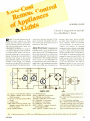
LOW -COST REMOTE CONTROL OF APPLIANCES AND LIGHTS
BUILD A SINE -WAVE INVERTER
SIMPLE TESTERS FROM "JUNKBOX" PARTS
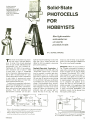
SOLID -STATE PHOTOCELLS FOR HOBBYISTS
63
65
67
71
73
How light- sensitive semiconductors are used in practical circuits.
IC SPEED CONTROLLER FOR HO MODEL RAILROADS
BUILD THE TRANSISTOR IDENTOMETER
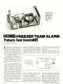
HOME FREEZER THAW ALARM
HOME COMPUTER BASICS
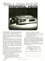
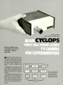
BUILD CYCLOPS
First all solid -state TV camera for experimenters.
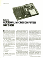
BUILD A PERSONAL MICROCOMPUTER FOR $100
Elf ll microcomputer trainer based on COSMAC 1802 microprocessor.
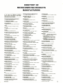
DIGITAL ELECTRONICS/MICROCOMPUTER PRODUCT DIRECTORY
MICROCOMPUTERS
COMPUTER PERIPHERALS
COMPUTER MODULES
DIRECTORY OF MANUFACTURERS
99
108
112
119
COVER PHOTO Conrad Studios
ELECTRONIC EXPERIMENTER'S HANDBOOK is published annually by Ziff-Davis Publishing Company at One Park Avenue.
New York, New York 10016. Hersel B. Sarbin, President; John R. Emery, Senior Vice President- Finance and Treasurer; Charles B. Selon, Secretary.
COPYRIGHT
rh.
1977 BY ZIFF -DAVIS PUBLISHING COMPANY. ALL RIGHTS RESERVED.
Material in this publication may not be reproduced in any form without permission. Requests for permission should be directed to
Jerry Schneider, Rights & Permissions, Ziff -Davis Publishing Co., One Park Ave., New York, NY 10016
The Publisher has no knowledge of any proprietary rights which will be violated by the making or using of any items disclosed in this Handbook.
JOSEPH E. MESICS, Publisher ARTHUR P. SALSBERG, Editorial Director IVAN BERGER, Senior Editor
EDWARD I. BUXBAUM, Art Director PATRICIA GIRRIER- BROWN, Production Editor GARY GARCIA, Assistant Editor
ANDRE DUZANT, Technical Illustrator JOSEPH E. HALLORAN, Adv. Director JOHN J. CORTON, Adv. Sales
LINDA BLUM, Adv. Service Manager EDGAR W. HOPPER, Publishing Director
3
Iatlitt II gilt
60HzCRYSTALTIMEBASE
This kit enables a MOS clock circuit
to operate from a DC power source.
Ideal for car, camper, van, boat, etc.
60Hz output with an accuracy of
.005% (typ.). Low power consumpfion 2.5 mA (typ.). Small size will fit
most any enclosure. Single MOS IC
oscillator/divider chip 5-15 volts DC
Texas
NO COD'S.
Money back guarantee.
residents add 5 °,, sales tax. Add 5% of order
for postage and handling. Orders under $15.00
Foreign orders add 10% for
add 75 cents.
postage.
For your convenience, call your BankAmericard
or Master Charge orders in on our Toll Free Watts
Line: 1- 800 -527 -2304. Texas residents call collect: 1- 214 -271-8423.
P.O. Box 38323E
master charge
'" '"'
Dallas, Texas 75238
""""
operation.
I
1918 ELECTRONIC
EXPERIMENTER'S
PATER 'S
HANDBOOK
PUBLISHING COMPANY
Hershel B. Sarbin
,.,,,-
ONLY
BANKAMERICARD
POPULAR ELECTRONICS
$5.95 each
President
Philip B. Korsant
.,4y.. b ,i
2
for
$10.00
Executive Vice President
Furman Hebb
14 pin
16 pin
18 pin
28 pin
40 pin
Executive Vice President
SOCKETS
low profile
low profile
low profile
low profile
low profile
.3C
.69
.89
CMOS
CD4000
CD4001
CD4002
CD4006
CD4007
CD4009
CD4010
CD4011
CD4012
CD4013
CD4014
co4015
CD4016
CD4017
CD4018
CD4019
CD4020
CD4021
CD4022
CD4023
CD4024
CD4025
CD4027
CD4028
CD4029
CD4030
CD4035
.19
.19
.19
1.20
.19
.47
.47
.19
.19
.32
.78
.7$
.32
.95
.95
.45
.97
.97
.97
.19
.75
.19
.45
.$9
.99
.35
.99
LS
.22
.25
CD4040
CD4041
CD4042
CD4043
CD4044
CD4046
CD4047
CD4049
CD4050
CD4051
CD4053
CD4056
CD4066
CD4071
CD4081
CD4507
CD4508
CD4510
CD4512
CD4516
CD4518
CD4520
CD4528
74CO2
74C04
74C107
1.00
.69
1.05
.60
.60
1.50
1.89
,qg
.49
1.25
1.25
1.15
.78
.19
23
1.00
.
2.80
1.10
1.10
1.10
1.10
1.10
.87
.25
.32
.79
741500 .26
741502 .26
741503 .26
741504 .30
741505 .32
741508 .26
741509 .26
741510 .26
741511 .35
741513 .58
741514 1.05
741515 .26
741520 .24
74LS21
74LS22
741526
74LS27
741 -530
741532
741537
741538
741540
741542
7
-
_S5
41554
741.555
7415145
7415151
7415153
7415155
7415156
7415157
7415158
74LS160
7415161
74LS162
7415163
7415168
7415169
7415170
7415173
7415174
7415175
7415190
7415191
7415192
7415193
7415194
7415195
7415196
7415197
7415251
7415253
74LS257
7415258
7415260
7415266
7415279
7415290
74LS293
7415295
7415298
7415365
74LS366
7415367
74LS368
7415390
74LS393
7415670
.35
.35
.35
.35
34
35
33
38
34
80
.26
.26
.26
.75
.49
74LS73
74L574
74LS76 49
741596 45
741590 55
74L592 1.00
74LS93 1.00
7415109 .49
74LS112 49
7415113 .40
74LS114 .40
7415125 .55
7415126 .65
74151321.00
7415133 .35
74L5136 .39
7415138 .85
RESISTORS
OVER 50,000,000
IN STOCK
1.00
.7o
.70
.69
.76
.95
.85
.85
.85
.85
.85
.85
.85
330 ohm
22K ohm
27K ohm
33K ohm
39K ohm
43K ohm
47K ohm
82K ohm
100K ohm
150K ohm
220K ohm
470 ohm
1K ohm
1.2K ohm
2.2K ohm
3.3K ohm
4.7K ohm
6.8K ohm
10K ohm
20K ohm
2.00
1.10
1.00
1.00
.95
.95
95
.95
.95
.85
.85
.85
.85
All resistors are PC lead,
but they are not pulloffs.
The leads are about 1/a ".
100 minimum order for
each value.
100/.99
NO MIX
1/8W
only.
'Value in
1 4W
otherwise
unless
specified. Most are 10%
tolerance.
.85
.85
05
.26
.26
.55
.75
.75
.95
.95
.55
.55
.55
.55
1.75
1.45
3.25
7415 139 .85
John R. Emery
Senior Vice President, Finance and Treasurer
Phillip T. Heffernan
Senior Vice President
Edward D. Muhlfeld
Senior Vice President, Sports Division
Philip Sine
Senior Vice President
Frank Pomerantz
Vice President, Creative Services
Arthur W. Butzow
Vice President, Production
Lawrence Sporn
Vice President, Circulation
George Morissey
Vice President
Sydney H. Rogers
Vice President
Sidney Holtz
Vice President
Albert S. Traina
Vice President
Paul H. Chook
Vice President, Market Planning
Edgar W. Hopper
Vice President
Robert N. Bavier, Jr.
Vice President
Charles B. Seton
RADIO HUT GUARANTEE
ORDER BY PHONE. Charge your
order to BankAmericard or
Master Charge.
USF OUR TOLL FREE WATTS
If you are not satisfied with any of
our products NO MATTER WHAT
THE REASON we offer you a full
money back guarantee if the product or products are returned within
14 days after you receive them.
1-800-527-2304
CIRCLE
NO
20
ON
FREE
INFORMATION
MAGAZÉ
CHARGE YOUR ORDER TO YOUR AMERICAN
EXPRESS. BANKAMERICARD. MASTER
CHARGE OR DINERS CLUB ACCOUNT.
CASES
I
£
dvI
YOUR FAVORITE ZIFF -DAVIS
MAGAZINES
The ideal way to save your valuable copies, keep
them well protected and make it easy for you to
refer to any issue at any time. Both decorative and
attractive enough to enhance the decor of any room,
a full year's copies. Constructed of
reinforced fiberboard, these durable cases are
covered in a rich- textured leatherette. The gold
4
Jerry Schneider
Vice President 8 Administrative
Director, Annuals
William Ziff
Chairman
W. Bradford Briggs
Vice Chairman
Ziff -Davis Publishing Company
CARD
Only $5.95 each, 3 for $15.50 in any combination
of titles, including all postage and handling charges.
Outside U.S.A. add $1 per case.
DELUXE
Secretary
m
Ziff -Davis Serv. Div., Dept.11, 595 B'way, N.Y. 10012
Please send the Magazine Cases indicated below:
TITLE
QUANTITY
CHECK:
All Black
Maroon Back, Black Sides
ENCLOSED IS $
BankAmericard
CHARGE:
EEH -78
Master Charge
Diners Club
American Express
Account #
Exp. Date
Master Charge Interbank #
(4 numbers over your name)
each case holds
Signature
Print Name
embossed back adds to its elegance and makes
each case a welcome addition to your bookshelf
or cabinet.
Cases are available for your favorite magazines.
Address
State
City
Zip
Residents of Calif., Col., Fla., Ill., Mich., Mo.,
N.Y. State, D.C. and Tex. add applicable sales tax.
Editorial and Executive Offices
One Park Avenue, New York, New York 10016
212- 725 -3500
Midwestern Office
The Pettis Group 4761 West Touhy Ave.
Lincolnwood, Illinois 60646, 312- 679 -1100
Gerald E. Wolf, Thomas Hockney
Michael Neri
Western Office
9025 Wilshire Boulevard, Beverly Hills, Cal. 90211
213- 273 -8050, BRadshaw 2 -1161
Western Advertising Manager, Bud Dean
Japan
James Yagi, Oii Palace Aoyama
6 Chome, Minato-Ku, Tokyo 407- 1930/6821
582 -2851
1978 ELECTRONIC EXPERIMENTER'S HANDBOOK is
published annually by the Ziff Davis Publishing Company,
One Park Avenue, New York, N.Y. 10016. Also publishers
of Stereo Review, Popular Electronics, Citizens Band
Handbook, Tape Recording and Buying Guide, Stereo Directory and Buying Guide, and Communications Handbook.
ELECTRONIC EXPERIMENTER'S HANDBOOK
m
ó
Oo
Pc
mrD
AMOD
^
CATHODE
00
/ DO
<O
mñ
Ñ
m
oN
m -
ó;
Z;
1
L
GO
O
N
N
-11C
,,
OGlwllmm
OD
DO41cn0 mm
2 a P O O D;
ti 0 s y C r
20 m ar m y
s"
r;Om2
2
n
N Z- ñ
0
-J
0
U
C N
a
C
Z
Cr.
D
m
n
O
O
o
O
C
Zor
o
xe*
tom
000
m
mmm
m
Dax
b
2
t
b
Z
C
-4
CO
O
°
;40
0
O
<
m
ó
ó
D
my
no
o
OV
o,
ow
mm
o0
mr^
Will
1978 Edition
!
CO
1111
o n
n
i
as
.p
CO
V
cO
A
u
5
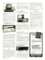
BASIC in ROM Computers
by Ohio Scìentìfic
If you're just getting into personal computing and are buying your first machine, you're probably confused by the myriad
of companies and products available.
However, there is one simple guideline you should follow
when choosing your first computer. Be sure that it is capable
of giving you full floating -point BASIC the instant you turn
it on. Machines with full 8K BASIC in ROM cost as little as
$298.00. Why should you settle for anything less?
Super Kit
Challenger UP
The Super Kit is a
3
board set with
a 500
board
(like the Model 500)without the serial interface.
The ROMs are configured for use with the included, fully assembled 440 video board to provide
a full BASIC computer and terminal.
The Super Kit also includes a fully assembled 8
slot backplane board which gives you 6 open slots
for expansion.
To be up and running in BASIC simply plug the
boards together, supply power ( +5 at 3 amps and
-9 at 600 MA), add an ASCII parallel keyboard
plus a video monitor or TV set via an RF converter
(not supplied).
Total price for the "kit" $398.00.
The Challenger IIP from Ohio Scientific is the ideal
personal computer complete with BASIC in ROM and
plenty of RAM (4K) for programs in BASIC.
Complete with an audio cassette interface, the Challenger IIP uses a full computer keyboard, not a calcu-
ro
lator keyboard.
In addition, the Challenger IIP comes complete with a
full 64 character -wide video display, not a 40 character
display. The user simply connects a video monitor or
home TV set via an RF converter (not supplied) and
optionally, a cassette recorder for program storage.
The Challenger IIP comes complete with a 4 slot
backplane and case for only $598.00. Fully Assembled.
El
Send me the Fall '77 Catalog. I enclose $1.
would like to order directly from this advertisement.
(Please allow up to 60 days for delivery)
I
NAME__
ADDRESS
CITY_.
_.
_STATE
_
To order: Payment by:
BAC (Visa) _
MC
Credit Card Account
Model 500
ZIP
_
Money Order
Interbank = (Master Charge)
Model 500 Boards @ $298.00
Challenger IIP @ $598.00
Super Kit @ $398.00
The Model 500 is a fully populated 8 x 10 P.C.
Board with 8K BASIC in ROM, 4K RAM, serial port
and Ohio Scientific Bus compatibility for instant expansion. All you need is a small power supply ( +5
at 2 amps and -9 at 500 MA) and an ASCII terminal
to be up and running in BASIC. And all for only
Ohio Residents add 4% sales tax
TOTAL CHARGED OR ENCLOSED
Order directly from: Ohio Scientific, 11679 Hayden St.,
Hiram, Ohio 44234 or your local OSI dealer
All orders shipped insured UPS unless otherwise requested.
L
$298.00.
J
OHIO #CIENTIFIC
Hiram, Ohio 44234
11679 Hayden
CIRCLE
6
NO
19
ON
FREE
INFORMATION
CARD
ELECTRONIC EXPERIMENTER'S HANDBOOK
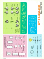
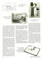
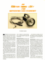
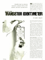
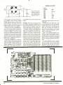
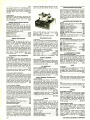
Build
A game of skill
and quick reactions
BY JAMES J. BARBARELLO
a power supply of from 5 to 15 V d.c.
Low current drain
in part to LED
-due
blanxing- allows standard -type batteries to provide many hours of play.
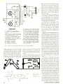
Operation. The game is
played by two people who alternate as
Pitcher and Batter. The pitcher's arsenal
consists of a left curve, right curve, and
straight balls. Each can be slow, fast, or
one of two changeups (a total of 12 different pitches). The "ball" is thrown and
travels its pitcher- determined route to
end up over home plate. The batter must
decide from which direction the ball is
coming and "hit" it as it passes over
home plate by depressing a switch corGame
HE "Batter Up" electronic game described here simulates the game of
baseball. It incorporates sufficient variations in "pitching" speed and changeups
to play the game without outgrowing it.
The strategy is to outfox your opponent
by determining which pitch is his weakness.
The circuit makes use of the familiar
555 IC timer, which works properly with
1978 Edition
responding to that direction (i.e., left,
center, or right bat). If the batter
"swings" too early or too late, it's a
strike. If the batter hits the ball and
keeps the bat depressed, a hit will be
displayed. The type of hit (single, double, etc.) is chosen essentially at random, but the batter's chances for each
type of hit are the same as an average
.300 major -league hitter.
To make the game more realistic (and
interesting), the batter can also hit into a
double play (counts as one out if no men
are on base). If the batter tries to cheat
and depress more than one bat simultaneously, more than one home plate
LED will light, indicating that a foul ball is
to be counted. A control on the playing
field allows the players to decide if they
wish to play in the Little, Minor, or Major
leagues. You can also add an option
that provides an audible signal (a short
beep) each time someone gets a hit.
7
H11
'
a
M
N
a
-"-'0-11111111-1iI
11
M
cv
o
A
-.
I
To-rco
a
in
¢
m
m
r
N
U
11
IIA
m v)
HUO)
-
M
N
IM)
a
a
z
LL
03
r
m
H U
a
1
m
1
N
CV
Q
co
R
Q
L
'
r
m
r
m
H U
n
OD
N
r
m
¢
m
m r-
CO
r
H U K)
r
c
m
in
HUi-
I I
-
N
1
n
a
1
T
a
U
N
11
N
N
U
HUtD
H UN
-
co
01
o
+I-
a
N
o
T
N
Q
D'
m
r
m
H U
-
OD
f
8
N
N)
m
H U N
cv
U
ELECTRONIC EXPERIMENTER'S HANDBOOK
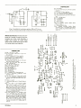
PARTS LIST
9V
B
+I,IHIi
-9 -V battery
I
CI , C2, C5, C6- --0.01 p.F, 25 -V disc ceramic
capacitor
C3-0.1 µF, 25 -V
R4
disc capacitor
C4-2.2 µF, 16 -V electrolytic capacitor
IC , IC2 -NE555V IC timer (or equiv.)
The following resistors are 1/2-W, 10% toler-
R5
R
RI
R3
PI
-3
2
I
6
R2
C4
ance.
C
l-3
1"
R2- I00.000 ohms
-2.2 megohms
R4- 47,000 ohms
I ,
R3
2
4
5
2
7
I
7
C
6
5
R5 -4800 ohms
SI-S.p.s.t. switch
C
-2"
dynamic speaker (Radio Shack
Spkr.
40 -245 or equiv.)
PI -Miniature phone plug
Misc.: Suitable enclosure (Radio Shack
270-230 or equiv.); 9 -V battery clip; tape or
epoxy; printed circuit board; hook-up wire;
SPKR
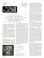
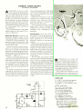
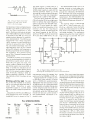
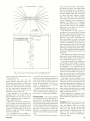
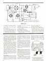
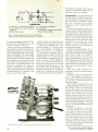
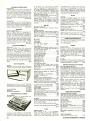
Fig. 2. Audible hit indicator option. When IC1 is on,
the tone is heard from 1C2 in the form of a 1 -sec. beep.
solder, etc.
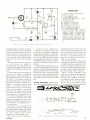
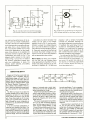
About the Circuit. The circuit is composed of a number of timers in the monostable (one shot) mode. Basically, a
trigger input causes an output pulse
whose width is determined by the value
of a timing resistor and capacitor.
i
_
®i
-
á itU
il
t
PARTS LIST
BI-B4-11/2-volt "C" cells
C I -C14, C I6 -C22,
1
HUN
tio
C24-C28-0.1 µF, 25 V
disc capacitor
C15, C23 -0.01 p.F, 25 V disc capacitor
IC I -IC9-NE555V IC timer (or equiv.)
LED I -LED 15- TIL-32 LED (or equiv.)
Q I , Q2-2N5I 29 (or equiv.)
The following resistors are 1/2-W, 10% tolerance unless otherwise noted:
RI, R3, R5, R7, R20, R22, R24, R26,
R28-I00,000 ohm
R2, R4, R6, R8- 470,000 ohm
R9 -R I2, R30 -R34-220 ohm
R 3-R 19- 10,000 ohm
R2I- 86,000 ohm
R23, R25- 390,000 ohm
R27- 68,000 ohm
R29- 220.000 ohm
R35
megohm, 1/2-W linear -taper pot
S.p.s.t. momentary pushbutton switch
(normally open)
S2, 53 -S.p., 3- section, 12 -pos. rotary switch
S4, 55, 56- Momentary pushbutton switch,
normally open (Poly Paks 92CU 1749, spec-
0--¢0,
as
-2
SI-
ify" ")
S7- S.p.s.t. switch
il-Miniature
phone jack
(if Sound Option
is
used)
Misc. -4" x 21/2' x 21" enclosure (Radio
Shack 270-231 or equiv.); 73/4" x 43" x
23á" enclosure (Radio Shack 270 -232 or
5 1/16" x 23/4" x 13" enclosure
(Radio Shack 270 -233 or equiv.); four "C"
cell battery holder (Radio Shack 270 -390 or
equiv.); 12- conductor flat cable (3 feet); solder; printed circuit board; etc.
Note -The following are available from
J.A.L. Associates, P.O. Box 107, Eatontown, N.J. 07724: Etched and drilled main
pc board (specify B -UP) $8.95; etched and
drilled set of three pc boards (main, Batter's
Box, and Sound Option, specify B -PKG)
$10.60. Price includes shipping. Alow 3 to
6 weeks for delivery. N.J. resdents add 5%
sales tax.
I'
co
i
n
HU-
ïr
-
j
0
m
m
-+ '/
tw
ö-tA =,Z -+W
am.
æ
ID
Y
:VD
is
J
io
2
T
ó
W
h
"4 \i
m
°w
J
¢
U
n
m
W
a
¢
HUr- N
"
v
1
f
j
f t'
H
1
I,)
¢
N
O
J
,
1
0
' Fr
o
¢
j j 'J
f t
N
j
O
W
c)
¢ v N
o
¢
a
I
T
E.:1-l.1
J
M
N
V Ú
'4)
(T)
r¢
_"
TO
jj
T
CIN
1
¢
7
W
-
1/)
6- ,z
wV
t
0
1
- j Wi
W31T
¢
°_.
o
N
N-
F
Cr
Ñ
U
U
6
CO
IO
O
.r
c)
equiv.);
1978 Edition
In
N
N
N
U U
so
H UD)
9
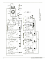
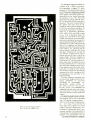
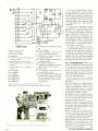
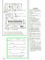
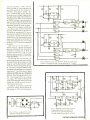
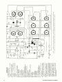
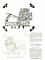
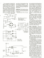
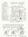
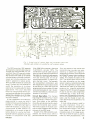
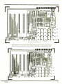
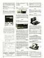
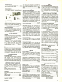
The schematic diagram for Batter Up
is shown in Fig. 1. When S1 is momen-
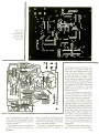
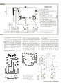
Etching and drilling guide for
main pc board of Batter Up.
10
tarily depressed, it triggers IC1, which
produces a 0.05- second -wide pulse at
pin 3. The pulse is capacitively coupled
to pin 2 of IC2. The negative edge of the
pulse triggers IC2 and the process proceeds down the line. Switch S3 grounds
the cathodes of one of the three LED
banks and one side of either S4, S5 or
S6. The grounded LED bank will light in
sequence. The switch corresponding to
the lighted LED bank must be depressed in order to ground voltage divider R13-R14 and stop the sequence. As
an example, assume S3 is in position 1.
When S1 is momentarily depressed,
LEDI, LED2, LED5, and LED8 will light
in turn. If S4 is depressed before C6
charges up to two- thirds of the supply
voltage, the sequence will stop at LED5,
which will remain lighted as long as S4 is
closed. Depressing S4 after LED8 is extinguished has no effect. Depressing S4
after 1C4 is triggered and before C8
reaches two- thirds of the supply voltage
(while LED8 is on), LED8 will stay on
and the junction of Q2 and R19 will be
grounded. Transistors Q1 and 02 will
now saturate, causing point C to go to
ground and point D to go to half of the
supply voltage. These two voltages are
routed to the ring counter made up of
IC5 through IC9. The ring counter is initiated when power is applied, but since
the LED cathodes are at V +, they do not
light. When the voltages at points C and
D are applied to the ring counter simultaneously, the voltage at point D halts
the counting. Point C then grounds the
cathodes of the LEDs, causing the LED
corresponding to the one timer in the
high state to light.
The time constants associated with
the ring counter stages produce the following
probabilities of occurrence
(expressed as percentages): sin trigle -66.67 %;
double -13.34 %;
ple- 3.34%; home run-10 %; and double play -6.67 %. The probabilities are
independent of each other and of previous occurrences. The rate of counting
makes the selection process sufficiently
random.
The pitching adjustment for Little, Minor, or Major League is made with R35.
The charging time for 1C4 is adjustable
from 0.05 second (charging resistor =
470 k) to 0.275 second (charging resistor = 2.47 meg.). Thus, the time the
home plate LED is lighted is 5' times
longer in the Little League than it is in
the Majors. Potentiometer R35 is continuously variable so that adjustment to
times between the indicated positions is
possible. This potentiometer only adELECTRONIC EXPERIMENTER'S HANDBOOK
COMMON
DRILL 6 HOLES
I/16" DIA.
DO NOT DRILL 4
REMAINING PADS
54
55
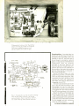
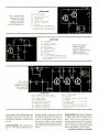
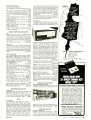
Fig. 4. Etching and
drilling guide and
parts placement for
Batter's Box. Note
that switches are
mounted on pc board.
S6
S5
S4
S6
PITCH
52A
Fig.
5:- Shown
53
526
SI
is switch winng guide for Batter's Mound.
justs the "on" time for IC4- generated
fast balls; slow balls still travel at the
same speeds. The league selection allows everyone -from small children to
the super- star
play the game and be
challenged by it.
A simple, but useful, option is an audible hit indicator. In Fig. 2, IC2 is an c scillator operating at about 2.5 kHz. Power
is applied to the oscillator only when pin
3 of IC/ goes high. (Timer IC1 is a one shot with an "on" time of about 1/4 second.) When a hit occurs, point C is
grounded. This negative step is integrated to a pulse by Cl and C2, triggering
ICI. When IC/ is on, the tone is heard
from 1C2 in the form of a 1/4- second
beep.
-to
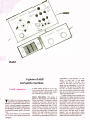
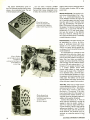
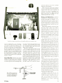
Construction.
Batter Up has been
configured as three separate enclosures: a pitcher's mound, a batter's box,
and a playing field. Each enclosure is a
standard Bakelite box. Printed -curcuit
construction makes assembly easy, but
the components could also be mounted
on a perforated board. If you choose
pert- board, you can use the components
placement diagram as a guide.
The\playing field box is 73/4' x 43/8" x
2 ;/s" (19.7 x 11.1 x 6 cm). The top plate
is drilled in accordance with the photo of
the prototype. All lettering can be transfer type, while linework and figures can
be made with an indelible -ink felt -tip
pen. Once the marking is completed, a
light coat of spray varnish will protect it
from marring. All LED's can be mounted
directly on the main pc board. Suitable
etching and drilling, and component
placement guides are shown in Fig. 3.
The pc board is mounted in the box on
machine -screw standoffs so that the
LED's protrude about 1/2' (3.2 mm)
above the top plate. The battery holder
is mounted under the pc board and the
power switch on the side of the case.
Two holes are drilled -one on each of
the short sides of the case -for the
wires going to the Batter's Box and
Pitcher's Mound.
PI
V+
o- R3-+
11
-CI5-RI-.
-R2-o
.-05-.
C6-
z
C
rC3-o
6-C2-+
i
f
GND
SPKR
c
2
6-R5-4
44-R4-
6. Etching and drilling
and parts placement
guides for Sound Option.
Fig.
1978 Edition
Inter-unit wiring is best done with a afoot length of flat cable (12- conductor is
satisfactory). This cable is extremely
flexible and will not interfere with play. A
7- conductor piece and a 4- conductor
piece are also required (both can be obtained from the 12- conductor piece).
The Batter's Box includes switches
S4, S5, and S6. Calculator switches
have been chosen as they seem to be
best for most people's reactions. A rectangular cutout 1/2" x 15/16" (1.3 x 2.4
cm) is made in the top plate. The
switches mount on the pc board, as
shown in Fig. 4. This arrangement holds
them in place. The cable enters the case
through a hole drilled on one of the short
sides and the four leads are soldered to
the undrilled pads. Once wired, the pc
board can be secured to the top plate
with tape or a few dabs of epoxy. The
case is 4" x 21/4 "x21/4" (10.2 x 5.7 x 5.7
cm). Lettering is the same as for the
playing field.
The Pitcher's Mound uses a 12 -position, 3- section, single -pole rotary switch
and is wired as shown in Fig. 5. Again,
the cable enters the 5-1/16" x 2%" x
15/H' (12.9- x 6.7- x 4.1 -cm) case through
a hole drilled in one of the short sides.
Sound Option.
If you plan to add the
sound option, mount a miniature (1/a" or
3.2 -mm) phone jack in the playing field
box next to the batteries and under the
main pc board. Connect it to the sound
option pads on the main board. A separate 9 -volt battery is used to power the
option. Suitable printed circuit etching
and drilling, and parts placement guides
are shown in Fig. 6. A 2" (5.1 -cm) speaker is used. It can be taped or epoxied to
the 31/4" x 21/2' x 11/4" (8.3- x 5.4- x
2.9 -cm) case top plate after it has been
drilled and lettered. A miniature phone
plug can be mounted directly in the bottom side of the case to mate with the
playing field jack.
Use. Although
it may appear to be easy
to get a hit, advancing the League setting increases the difficulty. Only the basic rules for a hit, strike, foul, out, etc.
must be understood before play can begin. You will soon notice how analogous
Batter Up is to actual baseball in terms
of pitcher strategy, batter's hand -eye
coordination, and overall competitive
spirit generated during play.
As with any other battery operated device, the game should be turned off
when not in use to preserve battery life.
When the LED's become dim and pitching cannot be initiated with the pitch
switch, it is time to change the batteries.
11
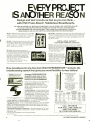
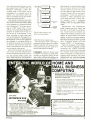
EVERY PROJECT
IS ANOTHER REASON
fast
think as you can
Design and test circuits as
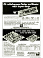
with CSC Proto -Board Solderless Breadboards.
R
As quick as pushing in or pulling out components, you can design, test, and modify all kinds
of circuits, with CSC Proto- Boards. Sockets are already mounted, on sturdy metal
ground /baseplates with non -marring feet. They're great for a wide variety of audio and
digital projects, and you save money by using components over and over again.
PB -101 -940 solderless tie points: ten 14-pin DIP
capacity. 140 five -point terminals plus 8 bus lines
t 30 tie -points each. 4.5 "W x 5.8 "L x 1.4 "H (114 x
147 x 35mm); 9 oz. (.26 Kg). Price: $29.95
PB -100 Kit -760 solderless tie points: ten 14-pin DIP capacity. 140
five -point terminals plus 2 bus lines of 30 tie -points each. Comes
with pre -assembled sockets, two 5 -way binding posts, base -plate,
all hardware. 4.5 "W x 6 "L x 1.4 "H (114 x 152 x 35mm); 7.5 oz. (.21
Kg). Price: $19.95
PB-102 -1240 solderless tie points: twelve 14 -pin
DIP capacity. 188 five -point terminals plus 6 bus
lines of 40 tie -points each and 2 bus lines of 30
points. 4.5 "W x7"L x 1.4 "H(114x 178x35mm);
10 oz. (.31 Kg). Price: $39.95
EXTRA LARGE CAPACITY
FOR MORE COMPLEX CIRCUITS!
PB- 103 -2250 solderless tie points: twenty -four 14 -pin DIP
PB -6 Kit -630 solderless tie points: six
14 -pin DIP capacity. Economical way to get
Proto -Board speed and convenience. 94
five -point terminals plus 4 bus lines of 40
tie -points. Comes with pre- assembled
sockets, four 5 -way binding posts, base plate, all hardware. 10 minute assembly
with pliers and screwdriver
capacity. 354 five -point terminals plus 14 bus lines of 50 tie points each, plus 2 bus lines of
40 points. 6 "W x 9"L x 1.4"H
(152 x 229 x 35mm); 1.251b.
(.57 Kg). Price: $59.95.
taw, fi
6"Lx4 "Wx 1.4 "H(152x 102x34mmI:
7 oz. (.20 Kg). Price: $15.95
P8-104 -3060 solderless tie
points: thirty -two 14-pin DIP
capacity. 472 five -point terminals plus 14 bus lines of 50 tie points. 8"W x 9.8 "L x 1.4 "H
(203 x 248 x 35mm); 1.75 Ib.
(.79 Kg). Price: $79.95.
Now, breadboard in any direction! With EXPERIMENTORTM sockets, the
breadboarding system that gives you more flexibility for less dollars!
i]
EXPERIMENTOR" 300
.3" centers, perfect
for smaller DIP's.
Ideal mate for
peripheral
microprocessor IC's.
6.0" x 2.1" overall
Just $9.95
Arrange EXPERIMENTOR
sockets to suit your circuit
instead of rearranging your
circuit to fit the breadboard.
LxPEfi1MENTQPk
6°v,tg111tN*
Discover the ease and convenience of
solderless breadboarding. CSC
f1lillliNllNllllNlllülll
EXPERIMENTOR* sockets let you
design, assemble and modify circuits
Botton, vlew
as fast as you can push in or pull out
components.
Large Capacity -Large sockets have
550 solderless tie points (94 five -point
terminals) plus two 40 -point bus strips.
Full Fan -Out -A CSC exclusive. The
only solderless breadboard sockets
Sockels lock together snap apart with full fan-out capabilities for microto handle any circuit
processors and other larger (0.6 ") DIP's.
Snap -together in a domino pattern- Arrange EXPERI MENTOR
sockets to suit your circuit. Expand or contract at will.
Simple Mounting -Vinyl insulated backing lets you mount EXPERMENTOR sockets anywhere without shorting. Mount to any flat
surface with 4 -40 flat head screws or 6 -32F self- tapping screws for
behind-the -panel mounting.
Accepts All Standard Components- Sockets conform to 0.1" grid
and are DIP compatible. Accepts IC's, diodes, resistors, capacitors,
transistors, etc.
Use #22 -30 solid AWG wire interconnections.
EXPERIMENTOR"" 600
6" centers, perfect
for microprocessors,
clock chips, RAM's.
ROM's. and PROM's
6.0" x 2 4" overall
Just $10.95
f
-
TIE POINTS
SPECIFICATIONS
5 Tie Points
Terminalst
Model Length
2 1"
3"
94(470)
6.0"
300
94(470)
2 4"
6"
600
6 0"
46(230)
3"
2 1"
3.5"
350
46(230)
6"
3 5"
2 4"
650
6.0"
0.75"
Ouad
Both units are 375" deep
t Number in parentheses refers to total number of
Width
Center
Channel
Bus
Stripst
2(601
2(S0)
2(40)
2(40)
4 (160)
Price
$9.95
$10.95
$5.50
$6.25
$4.00
tie-points
I
'D
S
CALL OR WRITE
FOR FULL LINE CATALOG
AND THE NAME
OF YOUR CSC DEALER.
Pat No 3235 554
All Prices Shown are Manufacturer's Recommended List. Prices and Specifications Subject to Change Without Notice.
12
ELECTRONIC EXPERIMENTER'S HANDBOOK
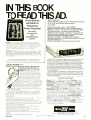
IN THIS BOOK
TO READ THIS AD.
...,. -
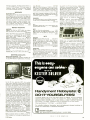
MEET MAX -100
CSC's 100 MHz 8 -digit Audio /CB /RF /Digital counter.
At $134.95, nothing else does so much
for so little.
* MAXimum frequency range -20Hz-100MHz
* MAXimum CB performance -ideal for CB applications
`MAXimum visibility -big, bright, 0.6" 8 -digit LED display
* MAXimum accuracy -crystal -controlled timebase
* MAXimum operating ease -automatic, no controls to set
* MAXimum range of applications -use for audio through
ultrasonic through RF: AM, FM and digital
* MAXimum portability -completely self- contained
* MAXimum versatility -use with clip -lead cable, in -line tap,
Proto- Boards
with Built-In
Regulated
Power Supplies!
Prolo-eowrd no.203
For extra
convenience
and
bread boarding
speed!
*
PB- 203 -Same capacity and layout as PB -103. plus short -proof.
fused 5VDC, to regulated power supply Ripple and noise are a
low lOmV at 0 5A Has on -off toggle switch and pilot light plus four
5 -way binding posts (2 for power) 9 75 "L x 6 6 "W x 3 25 "H (248 x
168 x 83mm) weighs 5lb (2 27 Kg) For 117VAC. 50 /60Hz
(220VAC available at slightly higher cost) Price $80 00
mini -whip antenna, etc.
MAXimum flexibility -choice of four power sources
PB -203A -All PB -203 features plus separate regulated +15VDC
and - 15VDC, 0.5A supplies, with internally and independently
adjustable output voltage. Same size as PB -203; 5.5 lb. (2.5 Kg).
For 117 VAC, 50/60 Hz (220 VAC, 50/60 Hz at slightly higher cost).
Price: $129.95
MAX -100 is a portable, high-precision frequency counter
that sets new standards in performance and value. In a
compact, portable case, it gives you continuous readings
from 20Hz to a guaranteed 100MHz, with 8 -digit accuracy.
Fast readings with 1/6-sec. update and 1 -sec. sampling
rate. Precise readings, derived from a crystal -controlled
time base with 3ppm accuracy. High -sensitivity readings
from signals as low as 30 mV, with diode overload protection
up to 200V peaks.
Input signals over 100MHz automatically flash the most
significant digit. And to indicate low- battery condition and
extend remaining battery life, the entire display flashes at
Hz. Price: $134.95
All Prices Shown are Manufacturer's Recommended List.
Prices and Specifications Subject to Change Without Notice.
LOGIC PROBE LP -1.
Compact, self -powered, multi -family probe with pulse
stretching and latching (memory)
capability for DTL, TTL, HTL, and
CMOS. By means of unique circuitry that combines the functions
of a pulse detector, stretcher and
memory, the LP -1 makes one -shot,
low- rep -rate, narrow pulses nearly
impossible to see, even with a fast
scope easily detectable and visible.
Input events positive and negative level
transitions, pulses, etc. -are automatically
detected by the LP -1's specially- designed Input
circuits. Pulses as narrow as 50 nanoseconds
are stretched to Y3 second and by simply setting
the PULSE MEMORY switch to the MEMORY
position, single -shot as well as low- rep-rate events
can be stored indefinitely.
To insure long trouble -free service, the LP -1 incorporates
a rugged, high- impact plastic case, built -in strain relief
power-cable. reverse polarity and over -voltage protection.
Price: $44.95.
HIGHLIGHTS.
HI and LO LED's blink on and off, tracking" -1.. and 0states at square wave frequencies up to 100Hz.
PULSE LED blinks on for Y3 second during pulse trains.
With square waves of up to 100KHz both Hl and LO LED's
will be activated: PULSE LED will blink continuously at 3Hz
rate to indicate level transitions.
With duty cycles of less than 30 %, LO LED will light, in
addition to PULSE LED blinking at 3Hz.
With duty cycles of more than 70 %, Hl LED will light, in
addition to PULSE LED blinking at 3Hz.
Input impedance is 100,000 ohms for minimum circuit
loading.
Maximum input signal frequency is 10MHz.
-
-
1978 Edition
1
SPECIFICATIONS
-
CIRCLE
NO
4
Range: 20 Hz to 100 MHz. guaranteed Gatetime: sec.
Resolution: Hz Accuracy: ± count + time hase error.
Input Impedance: M13 /56pF Coupling: AC Sine Wave
Sensitivity: 30 mVRMS @ 50 MHz Internal Time Base
Frequency: 3.579545 MHz x tal osc. Setability: ± 3 ppm @
25 °C Temp -Stability: Better than 0.2 ppm / °C, 0 -50 °C.
Max. Aging: 10 ppm /year. Display: Eight .6" LED digits.
Lead -zero blanking: decimal point appears between 6th and
7th digit when input exceeds MHz. Overflow: with signals
over 99.999.999 Hz, most significant (left hand) digit flashes,
allowing readings in excess of 100 MHz. Display update:
1/6- second plus sec. gate time. Low Battery Indicator:
When power supply falls below 6.6 VDC, all digits flash @ Hz.
Power: 6 AA cells (internal): External: 110 or 220 VAC
Eliminator /charger. Auto cigarette lighter adapter; 7.2 -10VDC
ext supply, Bat. Charging: 12 -14hr. Size (HWD): 75" x
5 63" x 7.75" (4.45 x 14.30 x 19.69cm.) Weight: Less than
1.5 lb. (0.68 Kg) w /batteries.
1
1
1
1
1
1
1
1
=M=
CONTINENTAL SPECIALTIES CORPORATION
70 Fulton Terrace, Box 1942, New Haven. CT 06509
203 -624 -3103. TWX 710 -465 -1227
West Coast: 351 California St., San Francisco, CA 94104
41 5- 421 -6872. Twx 910 -372-7992
ON
FREE
INFORMATION
CARO
13
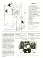
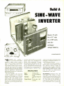
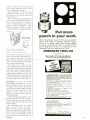
HERE IS a power supply package
incorporating a number of fea-
tures which make it not only unique
but extremely useful. First of all, the
package includes three separate
power supplies. Two of these are identical and are designed to supply independent operating voltages for transistor and integrated circuits -one can
be used as the positive supply, the
other negative. Each has an output
capability of up to 15 volts at 0.75 ampere, and the adjustable output voltage is regulated to 0.1% or better.
These two supplies are completely isolated from one another, which makes
it possible to stack them for higher
output voltage or to operate them at
different ground levels. (Parallel operation of the two supplies is not recommended since the very least voltage difference between them causes
undesirable interaction between the
two.) The supplies are generously
over -rated and can be operated at
maximum capacity on a continuous
basis without overheating.
The third supply is similar to the
other two except that it has a higher
output voltage and current capabilities. This supply is also very well
regulated, is adjustable, and will supply up to 50 volts at one ampere. The
lower limit of voltage output is approximately 8 V. This characteristic is intrinsic in the design. No attempt was
made to incorporate an adjust-to -zero
output capability because of the
added complexity and lack of need to
operate very near zero. (The minimum
output of the other two supplies is
about 1.5 V). This supply is handy for
performing odd jobs in conjunction
with the circuit under test, such as
powering a small motor, heater, etc. or
part of the circuit that requires higher
power. It can also be used as a battery
charger at 24 or 36 volts.
All three supplies have adjustable
current -limiting circuits and outputvoltage limiting capability. The current limiting can prevent destructive
conditions in case of accidental shorting or overloading of a circuit. This
feature also lends itself to operation of
the supplies as constant -current
sources, with the current level being
adjustable over a wide range. Over voltage limiting was added as a result
of the destruction of IC's due to adjustment of previous supplies to too
high a voltage level.
Each supply has its own meters for
continuously monitoring its voltage
and current output so there is no need
14
THREE -WAY
POWER SUPPLY
Two 0 -15 volts at 750 mA and one 50 volts at
1
ampere supplies have both voltage
and current limiting.
BY J.R. LAUGHLIN
to switch back and forth. The current
meters are dual -range due to the wide
range of currents available. Each supply also has an indicator light that
goes on when either current or over -
voltage limiting occurs.
Circuit Operation. The two lowvoltage supplies are identical, using
an integrated circuit as the regulating
device (Fig. 1). The IC drives a power
transistor, 04, to provide the output
current. The IC contains a very stable
voltage- reference source and a sensitive error -detecting amplifier. Regulation is accomplished by comparing
the output to the reference and any
discrepancy is corrected by the error
amplifier. Adjustment of the output
voltage is accomplished by varying
the amount of the output that is fed
back to the error amplifier (pin 4)
through R17. The reference voltage is
on pin 6 of the IC. It is divided by R2
and R3 and applied to the second
input to the error amplifier (pin 5).
Current output level is monitored by
01 with feedback through R7. The setting of R15 determines the amount of
feedback. When the feedback is sufficient for Q 1 to turn on, a signal is
supplied to pin 2 of the integrated circuit to adjust the output.
Voltage output is monitored by 02
with feedback through R9. The setting
of R16 determines the amount of
feedback and when it is sufficient to
turn on 02, 01 also turns on, supplying the limiting signal to the IC.
Whenever this signal is supplied to the
IC, it sends a signal to the base of 03,
which turns on limiting indicator 11.
Instead of an IC, the high -voltage
supply uses transistors throughout
(Fig. 2). The voltage reference is provided by zener diode D2. Comparison
of the reference to the output level
from R15 is made by 02 The current
output is monitored by 04 with feedback determined by R17. If 04 is
turned on, 05 is turned on to change
the output (through 03) and also to
ELECTRONIC EXPERIMENTER'S HANDBOOK
PARTS LIST
CI- 1041F,
20 -volt electrolytic capacitor
C1/4- 0.01 -µF ceramic capacitor
C3- 100-pF ceramic capacitor
C4 -4 -µF, 20 -volt electrolytic capacitor
C5- 20-pF, 20 -volt electrolytic capacitor
1R7
IK
-28 -volt, 40-mA lamp (Dialco
3917 -1471 -600 or similar)
ICI -IC voltage regulator (723)
I1
02
J ,J2
-5 -way connector (red,
507-
black)
I- 100 -mA meter (Monarch PMC75 or
similar)
M2-0-15 -volt meter (Monarch PMCl1S
I
M
ON PC
OR PERF
or similar)
BOARD
R9
Q1- Transistor (HEP7I5, 2N5367)
Q2- Transistor (HEP709, 2N5249)
Q3-Transistor (HEPS9100, 2N5308)
Q4- Transistor (HEP703, 2N3055)
Resistors -All 1/2-watt, 10 %r tolerance
I
-J
L
unless otherwise noted.
R 1,R3 -1500-ohm
R15
II
!On
LIMIT
CUR.
R2- 3900 -ohm
R4,R5,R7,R9 -1000-ohm
R6- 22,000-ohm
LIMIT
HEATr
SINK
1
R13
R10-100-ohm
.3n
R 11- 470 -ohm
R12- 1- megohm
R13-0.3-ohm
R14-Meter shunt (see text)
R15-10-ohm wirewound potentiometer
R16- 250,000-ohm carbon potentiometer
R17- 10,000-ohm, 10 -turn potentiometer
.m.knnnnAn.Annnnnn.
RI6
250K
R12
IM
Sl -Spst switch
*Two of each required
VOLT
LIMIT
RI
4700.
R17
I0K
OUTPUT
VOLTAGE
LEVEL
1978 Edition
*SEE
TEXT
41.)I20yF
J2OCOM
turn on 06 and energize the indicator
light. Voltage output is monitored by
07 with feedback from R16. When 07
turns on, 04 turns on as for current
limiting.
Conventional transformer and
full -wave rectifier circuits are used to
power each supply as shown in Fig. 3.
The individual transformers provide
complete isolation between the
supplies. Note that each supply is independent and their commons are not
connected to chassis ground.
Construction. Any type of enclosure
can be used for the three -way supply.
In this case a Bud CU -7127 cabinet
was used and the bottom plate was
constructed of 1/8" aluminum, drilled
for the three large capacitors. The
power supply rectifiers were mounted
on their own small board under the
bottom plate. In the prototype a two sided PC board was used for the electronics of all three supplies. The board
was mounted in an 18 -pin double
readout card connector. It might be
preferable to assemble each regulator
on a separate board for ease of con -
*RI4
100mA
0 -15V
C5
NOTE: DO NOT USE CHASSIS AS COMMON
Fìg. 1. Low- noltage supply (of which
there are two) uses an IC regulator.
.-iota i,atic voltage and current
limiting circuits activate the
ituliccttnr lamp 11.
SI
MI
M2
struction,
+UJI
installation, and future
maintenance.
The rear-panel heat sink should be
made of aluminum at least /8" thick
and perferably 1/4 ". The output transistor for the high -voltage supply was
mounted on a separate heat sink atVOLTMETERS
HIGH
/\
LOW
tached to the rear panel to increase
the surface area.
The current meters require shunts
for 1- ampere operation (R12 and R14).
These shunts can be wound easily by
hand using #28 enameled copper wire
and a 1 -watt carbon resistor (any valLIMIT ADJ.
HIGH
LOW
/
Arrangement gf component in prototype of triple power supply.
Three electronic regulators are mounted on double-sided circuit board.
15
07
DI
HEP
PARTS LIST
CI,C2- 10-11F,
20 -volt
Z0225
electrolytic
yF
ca-
15V
pacitor
03
C3- 20-µF, 50 -volt electrolytic capacitor
D1 -15 -volt zener diode (HEPZ0225)
D2- 6-volt zener diode (HEPZ0214)
40 -mA lamp (Dialco 50711 -28 -volt,
3917- 1471 -600 or similar)
Jl,J2 -5 -way connector (red, black)
Q1-Transistor (HEPS9100, 2N5308)
(HEPS000I,
Q2,Q5 -Q7- Transistor
2N5550)
R
Q3-Transistor (HEPS3021, MPSU03)
Q4-Transistor (HEP710, 2N5400)
Q8- Transistor (HEP241, 2N5069)
-All
Resistors
'h -watt,
less otherwise noted.
R 1,R2 -3300-ohm
R3,R8 -R 10 -1000-ohm
R4- R6- 10,000-ohm
R7- 470 -ohm, I -watt
10(7i
10K
tolerance unON PC
OR PERK.
R5
D2
BOARD
10K
HEP Z0214
6V
R11-0.3-ohm
1
J
L
R12 -Meter shunt (see text)
13- 270,000 -ohm
14- 470 -ohm
R15- 10,000 -ohm, 10 -turn potentiometer
R16- 10,000 -ohm carbon potentiometer
R
R
ZI
LIMIT
-10 -ohm wirewound potentiometer
Sl -Spst switch
R17
I0K
OUTPUT
VOLTAGE
R14
HEAT
SINK
R16
10K
R15
VOLT
LIMIT
LEVEL
I
R13
270K
47011
Fig. 2. The 50-volt supply is all
transistor and also has enrrent
and voltage limiting.
08
HEP24I
R17
1011
-
CUR.
LIMIT
RII
.311
MI
10OmA
*R12
+
o
L
JI
+C3
2oyF
J2
NOTE: DO NOT USE CHASSIS AS COMMON
ue) for the form. Of course, shunts can
be purchased for most high -quality
meters, but it is possible to wind the
shunts for less expensive models.
The ammeter shunts should be
RECT
T
mounted directly from the ammeter
terminals to the shunt switch terminals. The 0.3 -ohm resistors (R11 and
R13) can be mounted on the bases of
the transistor sockets.
I
MDA920A3
RI
3.9
CI
0001E
Fig. 3. The three independent
power supplies are conveutio2ta.l
bridge-rectifier circuits.
VÓ.
COM
RECT 2
T2
DA920A3
R2
3.9
C2
OOOyF
11M114
LOW
VOLT.
PARTS LIST
CI,C2- 1000 -0, 50 -volt electrolytic
capacitor
C3- 3500 -pF, 75 -volt electrolytic capacitor
F I- F3 -1/2- ampere 3AG fuse and holder
COM
I1
-117 -volt
neon lamp assembly
RECTI- RECT3- MDA920A -3 bridge
rectifier
R1,R2 -3900 ohm.
RECT 3
MDA920A3
COM
I17VAC
16
resistor
1
HIGH
VOLT.
CHASSIS
2 -watt
R3- 10,000-ohm, -watt resistor
Sl -Dpst switch
TI.T2-Transformer, 24-V, -A
1
F46X or similar)
T3-Transformer,
(Triad
40 -V. I -A (Triad F92A
or similar)
Misc. -Suitable cabinet (Bud C117127 or
similar), aluminum panel 31,,;' thick
(Bud PA3102 or similar), heat sink
3 "x4 "x I ",
mounting hardware, line
cord, power transistor insulators, terminal strips, capacitor mounts, knobs,
etc.
*SEE
o
TEXT
COM
The C5 capacitors in the low- voltage
supplies and C3 in the high -voltage
supply should be mounted directly on
the output binding post behind the
front panel. Use tie -points to hold R11
and R12 in the low- voltage supplies
and R13 and R14 in the high -voltage
supply.
Checkout. Check the rectifier circuits before connecting all the rest of
the circuits. If the rectifiers are all
right, connect the regulator circuits.
It is strongly suggested that, when
first testing the high -voltage supply, a
Variac (or similar source) be used to
provide a low voltage input at the start.
An oscilloscope should be used to
detect any tendency of the supplies to
oscillate. This should be done at several current and voltage output levels.
Regulation can be observed by using
various values of load resistors on the
supplies. The low- voltage supplies
should regulate to within about 0.2%
or better from zero to full load. The
current-limiting circuit will hold the
output current to the preadjusted level
regardless of the value of the load.,
ELECTRONIC EXPERIMENTER'S HANDBOOK
NRI CAN TORN TOUR
CB INTMES11' INTO PART-TIIIE
INCOME OR A CAREER
Career opportunities are
opening up fast for the man
trained in communications.
The field of communications is
bursting out all over. In Citizens Band alone, class "D"
licenses grew from
to over
2.6 million in 1975, and the
FCC projects about 15 million
U.S. CB'ers by 1979. That
means a lot of service and
maintenance jobs
and NRI
can train you at home to fill
one of the countless career
jobs available in design, installation and maintenance of
1
...
communications equipment.
Start training now, the NRI
way, to get your all important
FCC Radiotelephone License
and qualify for one of these
openings.
Learn on your own 400 channel, digitally- synthesized VHF transceiver
The NRI Complete Communications Course teaches you at
home to service and adjust all
types of two -way radio equipment (including CB), using the
one unit that is best equipped
to train you fo- CB, Commercial and Amateur communicat ons: a digitally- synthesized
Widest choice of courses
with Quadraphonic Audio
and Color TV Servicing
and AC power supply. This 2meter transceiver gives you
"Power -On" training. Then we
help you get your FCC Amateur License with special
instructions so that you can
go on the air.
NRI offers five TV -Audio servicing courses as well as
career courses in Digital Computer Electronics; Marine and
Aircraft Electronics; Mobile
Communications, and more.
.
More know -how for your
dollar
The complete program includes
48 lessons, 9 special reference
texts, and 10 training kits.
Included are: your own electronics Discovery Lab, a new
Antenna Applications Lab, an
Optical Transmission System,
CMOS Digital Frequency
Counter, and TVOM. The
course covers AM and FM
Transmission Systems; Radar
Principles; Marine, Aircraft,
and Digital Electronics; and
Mobile Communications. You
must earn your first class
radio - telephone FCC license
or you get your money back.
CB Specialist Course also
available
Over
NRI offers a specialized course
Send for the free NRI catalog
and discover why more than a
mil ion people like yourself
have chosen the NRI way as
the right way to get ahead.
Read how you learn at home
from bite -size lessons, progressing at your own speed to your
FCC license and then into the
communications field of your
choice. There's no obligation,
and no salesman will call.
Servicing. You get 37
lessons, 8 reference texts,
your own CB transceiver, AC
power supply and multimeter
for hands -on training. Also
included are 14 coaching un Is
to make it easy to get your
commercial
radiotelephone FCC
in CB
...
license, enabling you to test,
install and
a Million have
enrolled with NRI
service communications
equipment
400-channel VHF transceiver
If
card is missing, write to:
SCHOOLS
NRI McGraw
Continuing
NRI
IF/
II
1978 Edition
-Hill
Education Center
3939 Wisconsin Avenue
Washington, D.C. 20016
19
HOW TO PROGRAM
P-ONLY
MEMORIES
T
f
-
An experimenter's guide to programmable ROM's
what they are and practical applications for them.
BY ROBERT D. PASCOE
PROGRAMMABLE read -only memories are unique among the digital integrated circuits readily avail able to experimenters. What makes it
unique is that it is user programmable.
You decide what you want the PROM
to do and program it to do just that.
The only 'tools" you need area pair of
regulated power supplies, some
switches, and a resistor. The programming procedure itself is outlined
later on in this article.
The PROM is one member of the
standard ROM family of memories.
Once it is programmed, its memory is
nonvolatile. which means that, if
power is removed from and then reapplied to the PROM, the stored informat on remains intact. By contrast, a
RAM (random -access memory) has a
volatile memory; if power is inter rJpted, when it is again applied. whatever information was stored in the
memory will be erased.
The ROM (and PROM) can be made
from bipolar transistors, in which case
it is called a bipolar ROM. It can also
be made from metal oxide semiconductor devices, which makes it a
MOS -ROM. Whichever type it is. the
FOM is a digital device that "remembers" information on the standard binary format of 1's and 0's. The logic
levels remembered by the bipolar
20
ROM are the same as those used in
TTL circuits, whereas the levels remembered by the MOS -ROM are determined by the supply voltage required by the device itself.
Organization.
An important characteristic of the ROM is its organization.
The ROM remembers quantities of binary "bits" that are organized into
"words." Each word has a certain
number of bits. For example, one type
of ROM can remember 256 bits of in32 words of
eight bits apiece (32 words x 8 bits
256 bits).
Some of the more commonly available ROM's can remember 256, 1024,
2048, or 4096 bits in a single IC chip.
With the various types of ROM's. the
manufacturer determines how the
total number of bits is organized in the
formation organized into
chip.
The organization of the bits deter-
(A0
vcc
Vcc
Af-
2o
crw
o a
U
FUSE
oó
A3-
vco
CE
ONE OF
256 CELLS
FUSE
Fig. I. Purltrr' rlic+grrlm sllutt'.;
nolr/ two of .,'574 ,pu>>rrorll cFdts
urYrilcrhlr. ig a 256-bit ROM,
WWI
BO
81
82 B3 84 85 86
e7.
OUTPUT LINES
ELECTRONIC EXPERIMENTER'S HANDBOOK
SOME APPLICATIONS FOR PROM's
THERE are countless applications for the ROM. Some of the
more traditional ones use the ROM as lookup-table (trigonometry,
logarithms, etc.) memories in calculators; as micro- instruction systems in computers; and character generators for displaying alphanumerics on a CRT screen. The following are examples of what
you can do with an 8223 PROM:
Character Generator. A seven -segment display device can be
used to create the numerals 0 through 9, a number of upper- and
lower -case lettes of the alphabet, and some mathematical
punctuation-all with a single 8223 PROM chip. Because the display has only seven segments, it cannot form all 52 upper- and
lower-case or even all 26 upper- or lower -case letters.
In Fig. A is shown the logic diagram for an alphanumeric/
punctuation generator. Beside it is the "truth table" we used for
generating the 32 possible characters. Note that the entire memory
storage capability is "used up" in this truth table. (This truth table
assumes a buffering transistor between the outputs of the 8223 and
segments of the display. The display can be either an RCA 2100
incandescent or common -anode LED display. For common cathode LED displays, all B through B7 logic levels must be reversed.)
All eight output lines from the 8223 PROM are used, with one
output assigned to each segment of the display and a final one for
Figure
Displayed
Address
Outputs
(A, -A
(B; -B
0
00000
1
00001
2
c
00010
00011
00100
00101
00110
00111
01000
01001
01010
01011
01100
01101
01110
01111
10000
d
10001
E
10010
F
10011
G'
H
10100
3
4
5
COMMON-CATHODE
LED DISPLAY
DECIMAL
POINT
L
6
7
i
obiD
,
8
5V
9
a
=
A
SEGMENT
a ANODE
b
+5v
C
SEGMENT
g ANODE
+5V
h
10101
10110
i'
10111
J
11000
11001
L
11010
11011
11100
11101
11110
11111
n'
o
P
DECIMAL
POINT
ANODE
r'
U
Fig. A. Once PRU.1l is programmed according
truth table at right, it can generate nainhers,
letters, etc., on ?-- segment display device.
mines the number of address (input)
and output lines that will be available
in a given ROM. Address input pins are
the means by which a specific word in
the memory is accessed or selected. If
a particular ROM is organized with 32
words of eight bits per word, each
word can be addressed with five input
address lines (25 = 32). The address
00000 would be for word one, 00001
for word two, 00010 for word three,
and so on until 11111 would be for
word 32. The number of output pins
for a small memory is determined by
the number of bits used per word in
the memory's organization. In our example, the ROM would have eight
output pins.
The address lines for a ROM are
usually denoted by the legends A,,,
A.., etc., while the output lines would
A
1978 Edition
u
to
'These
letters
B
1
Segments
on
00111111
00000110
01011011
01001111
01100110
01101101
01111101
00000111
01111111
01101111
10000000
01000000
01001000
01110111
01111100
00111001
01011000
01011110
01111001
01110001
00111101
01110110
01110100
00010000
00011110
00111000
01010100
01011100
01110011
01010000
00111110
00011100
abcdef
bc
abdeg
abcdg
bcfg
acdfg
acdefg
abc
abcdefg
abcdfg
decimal point
g
dg
abcefg
cdefg
adef
deg
bcdeg
adefg
aefg
acdef
bbefg
cefg
e
bcde
def
ceg
cdeg
abefg
eg
bcdef
cde
capability.
B,, etc. For a
five -address -line input and eight -line
output ROM, the address pins would
be labelled A,,,
A,, A,, and A,, and
the output pins would be labeled B,,,
B,, B.,, B;,, B1, B - B,;, and B;.
Illustrated in Fig. is a basic 256 -bit
(32 -word by eight -bit) bipolar ROM.
The address lines are fed to logic
gates that decode the 32 possible
combinations of l's and 0's that appear on the five address lines. These
32-word lines are denoted by the
legends wl, through wl,,,. For the particular ROM shown, there are eight
output transistors whose collectors
are labelled B through B. The memory "cells are denoted by the legends
TI and T.. There are 256 of these basic
memory cells for a 256 -bit ROM.
The output lines from the ROM
A
)
are only approximations, included only to use up the
PROM's program
be denoted by B,I,
)
would be either high (logic 1) or low
(logic 0), depending on whether or not
a conduction path exists between the
memory cell and the output transistor
in each line. As an example, if a 0 is to
be stored at B in word 32, the T., resistance link (fuse symbol) must be
present. If, on the other hand, a 1 is to
be stored at B of word 32, the fuse
must be electrically removed (blown)
from the circuit.
Most ROM's have
a
pin labelled CE,
for "chip enable,' that permits the
output to be isolated from the rest of
the circuitry inside the IC. So, if a is
placed at CE (while the address is
being changed), the outputs will be at
the logic -1 level. The placement of this
specific binary information into the
ROM is called "programming. The
means of programming is determined
1
21
the decimal point. To use up the entire storage capability of the
PROM, the entire 00000 through 11111 series was used on the
address lines (A through A4). We will discuss later how to perform
the actual "programming" procedure for the PROM.
An extension of the single- character generator is the word
generator. Here, we have several PROM's and an equal number of
displays, each programmed with identical information. Depending
on the number of PROM's and displays desired, this system can be
used to generate words, strings of numbers, identification and
license numbers, etc. You simply set the address lines of each
PROM to generate the character you want.
Model RR Track Patterns. The PROM can also help an HO
model railroader remember track patterns for his train layout. As an
example, suppose an HO train layout has eight track switches and
10 possible track configurations. A PROM can be used to remember the positions of the various switches for the 10 possible
track patterns, as shown in Fig. B. The outputs of the PROM would
be connected to the track switches through electronic switches
(driver transistors). This ensures that the output voltage levels of
the PROM are converted to the proper voltages and currents
needed to move or position the track switches.
The PROM must be programmed with the appropriate binary
codes. The words w, through w,,, can then be the various track
patterns that the train can have. The one -shot multivibrator's output is coupled to the CE input of the PROM so that the switches do
-.
PATTERN
ENABLE
OSCILLATOR
Fig. B. In model-mal oad system, PROM
would be programmed to control all
possible combinations of switches on track.
by the type of ROM. The two major
types of ROM's are the custom programmed and the field -pro-
grammable ROM.
With custom -programmed ROM's,
the manufacturer places the binary information (links or no links) into the
memory as specified by the user. Custom programming of ROM's can be
very expensive when only small quantities are ordered. To reduce the high
cost of small quantities of ROM's,
manufacturers offer the field -programmable ROM or PROM.
The PROM is an ordinary ROM that
has all of its on -chip fuses intact. A
256 -bit PROM would have 256 of these
fuses, one for each bit of memory. The
user can program information into the
PROM simply by blowing selected
on -chip fuses. The fuses are blown
22
555
LIGHT
MB
TIMER
LIGHT
PATTERN
TIMER
+5V
LIGHT
-I
555
TIMER
DAY /NIGHT
TIMER
Fig. C. Clocked by timer circuit, 7490
counter delivers a 4-bit input to PROM,
which controls triacs to turn, lights on and off.
not have voltage across their coils continuously. With the PROM
remembering the various track positions for the eight switches,
you need only select the pattern you wish and push a button to
initiate the selection of that pattern.
Intruder Deterrent. When you go away from home for a day or
longer, you probably use mechanical timers to turn on and off
house lights to make it appear that someone is home. A PROM can
be used for this purpose and is much more effective in deterring
intruders than are mechanical timers.
Shown in Fig. C is a system, built around a PROM, for turning on
and off house lights in a certain sequence. Suppose that there are
eight lights located throughout the house. The lights can be controlled by individual triacs, with the triacs controlled by the outputs
from the PROM.
Assume that 10 light patterns are to be used in the evening hours.
Word one can be a basement and a living room lights -on command, word two can be a living room and a kitchen lights -on
command, and so on.
The various patterns of lights (words) can be selected by changing the address inputs, which are connected to a 7490 decade
counter. A 555 timer can be used to change the outputs, of which
there are a possible 10, of the 7490. This, in turn, changes the
lighting sequence for the house. With this arrangement, various
lights in the house can be changed every so often to give the
appearance that someone is home and moving from room to room.
a specific amount of
current through them for a specified
period of time. (The Signetics 8223 is
an example of a 256 -bit PROM. It is
readily available from a number of
surplus -parts suppliers for about
$3.00. This PROM is organized into 32
words of eight bits per word.)
open by passing
Erasable PROM's. ROM's are usually thought of as having permanent
binary information programmed into
their memories. Once information is
programmed into an ordinary ROM, it
cannot be altered. Recently, however,
a new type of PROM-the erasable
PROM-has become available. This
type of PROM permits information
stored semi -permanently to be erased
and new information to be reprogrammed in.
One type of erasable PROM, the
2048 -bit MM5203, is made by National
Semiconductor Corp. It can be erased
by concentrated shortwave ultraviolet
light. (It is available, surplus, for about
$9.00.The MM5203 is housed in a
16 -pin dual in -line package (DIP) with
quartz top that is transparent to
shortwave UV light. The 2048 bits are
organized as either 256 words of eight
bits per word or 512 words of four bits
per word.
The advantage of the erasable
PROM, as opposed to the nonerasable
PROM, is that it can be used over and
over again for different programs. The
a
information is simply
erased by directing UV light through
the IC's quartz "window" and reprogramming as desired.
Another type of erasable PROM
unwanted
ELECTRONIC EXPERIMENTER'S HANDBOOK
+12.5V +5v
SI
PUSH TO BURN
PREPARING A
PROGRAMMING AND
ADDRESSING TRUTH
TABLE FOR PROM'S
TEST
2.7
output lines feeding the 8223's
A;,A.A,A address lines respectively,
would be:
A,A:,A,A,AB,B,;B,B,B:,B,B,B
DCBA
g
f
e d c
0
X 0 0 0 0 X
0
1
1
1
X 0
2
0 0
X 0 0 1
1
1
0 0 0 0 1
0 X 1 0 1 1 0
1
X 1 0 0 1 1
1
X
b a
1
1
1
0
1
1
1
1
3
4
X 0
0
1
X 0
1
0 0 X
1
1
0 0
1
1
0
5
X 0
1
0
1
X
1
1
0
1
1
0
1
6
1
1
0 X
1
1
1
1
1
0
1
7
X 0
X 0
1
1
1
X 0 0 0 0
1
1
1
8
X
1
0 0 0 X
1
1
1
1
1
1
1
9
X
1
0 0
1
1
0
1
1
1
1
1
X
n
S2B
Ovo -15v
I
'.
/n this programming ..etap, Huth portier styptics
regalnted. O,ice PRU:11 is programmed, its
I,/emoy/ ea!, he checked as described iIi the test.
Fig.
mast
be
-this
one not so readily available to
experimenters -is the Nitron Company's NC7010 EAROM. This device
can be erased electrically in one
second. It can be erased and reprogrammed up to a million times. The
NC7010 is organized as 512 words of
two bits per word.
How to Program a PROM. The
8223 PROM used in the applications
described is shipped with all of its
outputs at a logic-0 level. This means
that all of its on -chip fuses are intact.
If a logic
is to be written into the
PROM's memory, the fuses must be
blown. The procedure for blowing selected fuses is called programming.
It can be performed with the circuit
shown in Fig. 2. The +5- and +12.5volt power supplies must be regulated. Switch S1 is a two -circuit pushbutton switch, with one set of contacts
normally open and the second set normally closed. Switch S2 is a dpdt slide
or toggle switch, while switch S3
must be a non -shorting rotary switch
with eight or more positions.
After wiring together the Fig. 2 circuit, program the PROM as follows:
1. Set S2 to the BURN position. (Note:
Never operate S1 when S2 is set to
1
BURN.)
The DCBA in the heading represents
the outputs from the 7490, while the
gfedcba represents the display segments controlled. The X's are
don't-care states, since there is no
input to the A, input nor output termination for the B, output lines of the
8223 PROM.
1978 Edition
S2A
o
BURN
Because the PROM is a logic element, programming and addressing it
must conform to the rules of logic. To
do this, a truth table must be drawn up
for the programming procedure. This
same truth table is also used for addressing the ROM after programming
has taken place so that stored information can be retrieved.
There are two approaches you can
use when working up your truth table.
The first is an arbitrary table, used
mainly for demonstration purposes.
Since you would key in the address
codes by manually setting switches,
you can use any address system that
suits your fancy. The truth table accompanying the diagram in Fig. A is an
example of the arbitrary approach.
For more practical applications, address code selection would be under
the control of the digital system in
which the PROM is to be used. In this
case, the programming truth table for
both input and output codes must conform to those required by the system. A
typical example is a BCD -to -7- segment
decoder.
Let us assume a 7490 decade
counter's encoded output is to be used
to drive a seven -segment LED display.
All decoding can be accomplished
with a PROM. The PROM will then feed
inverter /buffer transistors, which in
turn will power the display's segments.
The truth table, with the 7490's DCBA
NO.
39
2. Feed the proper logic -1 ( +5 -V)
and logic -0 (0-V or ground) code for
word one onto address lines A
through A, via S4 through 58.
3. Set S3 to the first PROM output
line position in which a fuse is to be
blown according to your programming truth table.
4. Depress S1 for about a half second and release. This action, in blowing the fuse, develops considerable
localized on -chip heat; so. do not
depress Si for longer than
a
full
second.
5. Allow several seconds of cooling
down time for the chip.
6. Set S3 to the next output line in
which a fuse is to be blown.
7. Repeat steps 4 and 5 for each output line in which a fuse is to be blown.
8. Set S4 through S8 for the logic
required for word two.
9. Repeat steps 3 through 7.
10. Continue to address the PROM
for each succeeding word, repeating
steps 3 through 7 as you proceed from
word to word, until you have completed programming the PROM.
The schematic diagram shown in
Fig. 2 depicts a program and test circuit. As you finish steps 3through 7for
each word, set S2 to TEST (do not
change the address code yet) and, observing the meter, check the PROM's
outputs by cycling through S3's positions. Logic 0 will be indicated by the
pointer swinging to near the scale's
zero index, while logic 1 will be indicated by about a +5 -volt reading.
Once you have verified that the program has "taken" fora given word, set
up the circuit for programming into
the PROM's memory the next word
that you want.
After making sure that the PROM is
properly programmed, affix some
identifying code on its case and truth
table and file away the latter in a safe
place where it will not get lost.
4
23
LOW -CMT
COMPANDER
ENHANCES HI -FI RECORDINGS
BY CRAIG ANDERTON
Simple accessory expands or compresses
playback's dynamic range.
Ince the dynamic range of live
is usually greater than the
range that discs and tapes can handle,
it is standard practice to introduce a
certain amount of level compression
when a recording is made. Unfortu-
ear music
nately, this compression limits many
crescendoes and percussive transients that add to the enjoyment of the
music. Thus, it is desirable, on playback, to expand the volume to replace
the missing peaks. On the other hand,
TAPE
MON.
R5
EXPAND
15K
_)
IN
OUT
R7
OOK
220yF
K
RI
50011
OI
J2
MON.
MON.
R9
10K
J4
-.AANV
TAPE
OUT
R6
D3
IOOK
DI-3=IN4001
D5
IN4001
PHOTOCELL
LEADS
15112
0II
6011
--yF
6.3V
+
RIO
5K
5K
TO OTHER
CHANNEL
117
J1 toJS -Phono jack*
LEDI -MV50 light emitting diode (or
011-Optical isolator (Clairex CLM6000
or similar)*
RI -500 -ohm linear taper potentiometer*
R2-27 -ohm,
5 %, 1/4-watt
resistor*
R3-220 -ohm, 5 %, 1/4 -watt resistor*
R4-33 -ohm, 5 %, 1/4-watt resistor*
R5- I5.000 -ohm. 5 %. 1/4-watt resistor*
R6- 100,000 -ohm linear taper potentiometer*
R7,R8- 100,000 -ohm,
5 %,
'/4
-watt
-watt resistor*
R10,RI1-5000-ohm linear taper potentiometer
R12-560-ohm, 5%. 1/4 -watt resistor*
S1 -Spdt (center off) switch*
1/4
S2-Spdt switch*
VAC
ND1N4001
24
PARTS LIST
1- 220 -pF, 50 -volt, electrolytic capacitor*
C2- 1000 -pF, 15 -volt, electrolytic capacitor
DI to D5- 1N4001 diode (or similar)*
C
R9- 10,000 -ohm, 5 %.
KA
RII
background.
To provide either expansion or
compression of the sound, the simple
compander described here can be
resistor*
GREEN
DOT
1C2
1000
TI
as a
similar)*
I
CLM6000
R3
22011
it is sometimes necessary to eliminate
loud level changes when using music
Fig. 1. "Sample" input to
compander is same as
input to the speaker.
T1-6.3 -volt filament transformer
Misc.- Perforated board, mounting clips,
suitable chassis, lettering, line cord,
knobs, moutning hardware, etc.
*Double quantity for two channels.
ELECTRONIC EXPERIMENTER'S HANDBOOK
QP
cOMPR
.2
.4
.6
INPUT-VOLTS
.8
1.0
RMS
Graph shows how compander
Fig.
expands or compresses the
relative output across speaker.
As the sampled signal increases, resistance of the photocell decreases,
increasing the output at J5. This provides the desired expansion.
When Si is in the COMPRESS posi-
the tape -monitor jack on the amplifier.
By switching the amplifier's tape
monitor to "in," the compander will be
put into the circuit.
tion, the photocell is connected
Checkout. With the system properly
across R8 so that, as the sampled
signal increases, the output at J5 de-
connected (be sure not to confuse the
channels) and operating, adjust each
channel's calibrate control (R10 and
R11) until the front -panel monitor is
just illuminated. Proper adjustment
here provides the best linearity and
channel balance.
Working with one channel at a time,
place S1 in the EXPAND position, the
sensitivity control (R1) at minimum,
and the depth control (R6) at maximum. Turn up the volume on your system to the most comfortable listening
level. Then advance the sensitivity
control until LED1 starts to flicker.
Avoid bright peaks on the LED. The
music should sound more accented,
with a greater dynamic range. Operate
the depth control to obtain the desired
amount of expansion. To be sure everything is working, turn off the compander and note how much flatter the
music sounds.
To check compression, place S1 on
COMPRESS and the sensitivity and
depth controls to maximum. Turn up
the volume. You should note that the
audio output does not rise above the
preset level. Adjust both controls to
obtain the best output.
At some low listening levels, there
may not be quite enough signal to
drive the compander properly. This
produces a "breathing" effect which
can be remedied by turning up the listening level or turning down the depth
control. This effect may also occur if
the calibration controls are not set
high enough.
There is no such thing as the optimum amount of expansion. Some
recordings require less than others.
However, most will benefit from the
extended dynamic range.
creases.
The curves in Fig. 2 are typical of the
expansion compression effects.
2.
hooked up between your preamp and
power amp or through the tape
monitoring circuit. (A compander is
not to be confused with devices such
as tone controls and equalizers, which
alter the frequency response of a system.)
Circuit Operation.
The heart of the
compander circuit (Fig. 1) is an optoisolator (0l1), which contains a light
emitting diode and a low- distortion
photocell in a light-tight plastic enclosure. This unit has much faster response time than devices using an incandescent lamp (often used in companders). It also introduces less distortion and has the advantage of providing a slight "slow release" action to
enhance the expansion effect.
The audio signal at the speaker terminals of the amplifier is applied to
connector J1. The level is controlled
and reduced by R1, R2, and R3, with
diodes D1 to D3 acting as voltage
limiters to protect the LED's. The
signal level is monitored by LED1. The
brightness of the LED in 011 varies
with the signal causing the resistance
of the photocell to vary.
The power supply provides a small
dc voltage (adjusted by R10) to keep
the two LED's within their conduction
range. This prevents a sudden snap in
the volume when a signal is applied.
With S1 in the oFF position and S2
on our, the input signal at J3 is applied
to R7 and R8 and the output at J5 is
half of the input. This insertion loss is
required to create the "headroom"
needed for expansion.
When S1 is in the EXPAND position,
the photocell in 011 is connected
across R7 to vary the resistance of the
upper half of the voltage divider. This
changes the output on J5. Potentiometer R6 acts as a "depth" control
to determine how much the variations
in the photocell resistance affect the
voltage divider.
1978 Edition
Construction. The complete circuit,
with the exception of transformer Tl
can be assembled on perforated
board. The transformer should be located as far as possible from the signal
leads to avoid pickup.
The circuit shown in Fig. 1 is for one
channel, except that the power supply
can handle two channels for stereo.
Mount the various phono jacks and
the two calibrate controls (R10 and
R11) on the rear apron (suitably identified) and the switches and depth
potentiometers on the front panel. The
two monitoring LED's can also be
mounted in rubber grommets on the
front panel. An on /off switch can be
used in the primary of Ti or the corn pander power supply can be plugged
into a switched recep.)acle on the
preamplifier.
,
System Hookup. The compander
will work with any amplifier that delivers two watts or more of output. If you
have a separate preamplifier /poweramplifier setup, use the hookup
shown in Fig. 3A. Use shielded audio
cables to interconnect the three devices. Be sure the "hot" side of the
amplifier output is fed back to the
compander.
If you have an integrated unit, use
the hookup shown in Fig. 3B. Connect
a shielded audio cable from the tapeoutput jack of the amplifier to J5 of the
compander and another shielded
cable from J2 on the compander to
J5
POWER
AMP
SPKR
(A)
INTEGRATED AMP
TAPE
TAPE
MON
OUT
ICOM PAN DER
J5
SPKR
Fig. 3. If you have
separate preamp and
power amplifier, use
hookup at (A). For
integrated amplifier,
use (B). Both are
for one channel only.
J2
(e)
25
Circuits happen Faster and Easier
with Super-Stripi
As little
as
17
Now, whenever you'd like to give a circuit
try, you can build it up nearly as fast as you
can dream it up with Super- StripsTM, the faster, easier
and less expensive solderless breadboards from A P
Products. When you build your circuit on a Super Strip, everything stays as good as new. Once you're
through, you can use everything again and again. Instantly. Put a Super-Strip to work for you. Eight distribution lines handle signal and power, and 128 five tie-point terminals can handle 9 ICs and then some.
It's a whole lot easier than printing a circuit
and a whole lot handier than haywire.
a
Part
Number
Model
Number
923252
923748
SS -2
SS -1
Price
Terminal
Type
nickel -silver
gold -plated
Each
$17.00
$18.90
Order from your. A P distributor today. Our distributor
list is growing daily. For the name of the distributor
nearest you call Toll -Free 800 -321 -9668.
Send for our complete A
catalog, the Faster and
P
Easier Book.
A P PRODUCTS INCORPORATED
Box 110 Painesville, OH 44077 (216) 354 -2101 TWX: 810 -425 -2250
You've seen the rest...
now try the best.
Solderless
strips, backing
board and binding
posts. Everything you
need to build and test your
own circuit. Used to be you'd
get a circuit idea, lay out a pc board,
print it, solder everything together,
trouble- shoot, change your layout,
try a new board, and spend absolutely too much time breadboarding.
Now A P ACE All Circuit Evaluators
let you breadboard in a fraction of
the time. Make your changes immediately. Keep full leads on your
components. Avoid the heat damage
possible with repeated soldering
and de- soldering. A P made the first
modern solderless breadboard, and
we still make them best.
26
Pick an ACE for Faster and
Easier solderless circuit
building and testing.
Part
No.
923333
923332
923334
923331
923326
923325
923324
ACE
Model No.
200 -K (kit)
208 ( assem.)
201 -K (kit)
212 (assem.)
218 ( assem.)
227 ( assem.)
236 (eisern.)
Order from your A
Send for our complete A P catalog,
The Faster and Easier Book.
Tie
DIP
Points
Capacity
8 (16's)
8 (16's)
12 (14's)
12 (14's)
18 (14's)
27 (14's)
36 (14's)
728
872
1032
1224
1760
2712
3648
P
distributor today. Our
distributor list is growing
daily. For the name of the
distributor nearest you call
Toll -Free 800 -321 -9668.
No.
Buses.
2
8
2
No.
Posts
2
2
2
2
2
4
4
8
10
28
36
Board Size
(inches)
4- 9/16x5 -9/16
4- 9/16x5 -9/16
4- 9/16x7
4- 9/16x7
6- 1/2x7 -1/8
8x9-1/4
10- 1/4x9 -1/4
Price
Each
518.95
28.95
24.95
34.95
46.95
59.95
79.95
A P PRODUCTS
INCORPORATED
72 Corwin Drive
Painesville, Ohio 44077
Box 110
216/354 -2101 TWX: 810-425-2250
ELECTRONIC EXPERIMENTER'S HANDBOOK
Great Jumpers are here:
State of the art
flat cable connector assemblies
at affordable prices.
..
Great Jumpers come to you fully pre -assembled
and fully pre-tested. Cable strain reliefs are integral to
the molded -on connectors. And we've designed in
complete line -by-line probeability with probe access
ports behind each contact.
Our connectors are industry standard; two parallel
rows of contacts, spaced every .1".
Great Jumpers come in five popular cable widths:
20, 26, 34, 40 and 50 lines wide, and in lengths ranging
from 6" to 36 ".
Available now at the distributor near you who carries the A P Products Faster and Easier Line.
Our distributor list is growing daily. For the name
of the distributor nearest you call Toll -Free
800 -321- 9668.
Send for our complete A P catalog, the Faster and
Easier Book.
Faster and easier is what we're all about.
A P PRODUCTS INCORPORATED
Box 110
72 Corwin Drive Painesville, OH 44077 (216) 354 -2101 TWX: 810 -425 -2250
Correct with a little help from AR
Intra- Switch
Intra- Connector and Intra- Switch do
for flat cable systems what our IC Test
Clips do for DIPs, which can do a lot
for you.
right in to switch each line, independently. So it's
great for diagnostic and quality testing, terrific for
programming or selective line inhibiting.
Intra- Connector and Intra- Switch are available
in 20, 26, 34, 40 and 50 contact versions at the
dealer or distributor in your area who stocks our
Faster and Easier Line. You can locate him by calling our toll -free number, 800 -321 -9668.
lntra- Connector mates in -line with standard
double row socket connectors. It has one set of female contacts, but two sets of male, at right angles.
So it provides instant line -by -line probeability.
and, allows for attachment of test probes,
components or an additional connector.
Intra- Switch plugs right in line, too. But
small, dependable slide switches are built
Faster and easier
is what we're all about.
A P PRODUCTS INCORPORATED
Box 110. 72 Corwin Dr., Painesville, OH 44077
1978 Edition
CIRCLE
NO
I
ON
FREE
(216) 354 -2101 TWX: 810 -425 -2250
INFORMATION
CARD
27
UNNECESSARY muscular tension
is known to be one of the contributing factors to psychosomatic illness. Unfortunately, much of this
muscular tension is subconscious so
many people can't relax because they
aren't aware of the tension. Consequently, many methods have been devised to provide recognition of tension
and encourage relaxation -including
yoga and "autogenic training"
(biofeedback techniques).
To detect muscular tension scientifically it is only necessary to measure
the minute electrical signals generated by a muscle when it is working.
This is done by an electromyograph
(EMG). The EMG has electrodes which
are placed in intimate contact with the
skin over a given muscle. When the
muscle is under tension, the EMG provides either a visual (meter) or audible
indication of the muscle tension. The
person to whom the electrodes are attached then becomes part of the feedback loop through his eyes or ears and
can try to reduce the tension by mental
or physical means. With this electronic aid, a person can learn to eliminate or greatly reduce the tension,
thereby bringing about changes in
general well- being.
Relaxation is not achieved instantaneously, and many training sessions
may be required in difficult cases.
Since emotions play a large role in the
production of tension, unexpected
feelings may be experienced when
one becomes familiar with "letting
go." The simple EMG feedback
monitor described here can be used to
practice muscle relaxation and also to
explore the building up of muscles.
A block diagram of the monitor is
shown in Fig. 1. The minute (microvolts) muscle signals detected by
the skin electrodes are amplified and
then applied to a rectifier/integrator
stage. The pulses are averaged and
either displayed on a meter or used to
drive a voltage -controlled oscillator
that generates a series of clicks for the
audible signal. The amount of muscular tension -and the magnitude of the
EDITOR'S NOTE
This muscle monitor is intended for
experimentation and entertainment
only. It is not to be used as a substitute
for professional clinical therapy. Persons with heart disease, high blood
pressure, or any other tension -related
illness should consult a physician. The
monitor is not to be considered a home
remedy for any illness.
28
BUILD A
MUSCLE
FEEDBACK
MONITOR
New biofeedback
technique helps
to reduce tensions.
BY MITCHELL WAITE
voltage picked up by the electrodes
-varies the reading on the meter and
the frequency of the clicking sound.
How It Works. In a device of this
type, the differential input preamplifier is the most important stage (Q1,
Q2, and ¡Cl in Fig. 2). This is because
common -mode signals such as stray
60 -Hz fields and associated line
noises, put a limit on the signal resolution. The circuit's common -mode
input impedance is compared to the
source unbalance to determine the
maximum common -mode rejection
ratio.In the circuit, op amp ¡Cl is used as
a bootstrap element. The common mode signal on the collector of current source Q3 is fed back to the input
through R3, R4, and R5 so that the
common -mode signal actually "sees"
an impedance much higher than the
values of these resistors. With this circuit, the balance between C1 -R1 and
C2 -R2 and the impedance of the elec-
trode
determines the overall
common -mode rejection. Making Cl
and C2 larger in value improves
common -mode rejection but also increases the recovery time due to transients at the electrodes. Input noise in
the circuit is minimized by using low noise transistors and designing the
collector currents for low noise. R -f
interference
is
drained
off
by
capacitors C3 and C4.
The output of the preamplifier is applied to 1C2, a high -gain, noninverting
amplifier. Associated with the amplifier are a low -pass filter ( -3 dB at
1
kHz) made up of C6 and R11 and a
high -pass filter ( -3 dB at 200 Hz)
made up of C7 and R12. A second
high -pass filter (Q4) further reduces
low- frequency components. Sensitivity is set by R25 and the signal is applied to a gain -of -30 noninverting amplifier (1C3), which also acts as a rectifier, integrator, and meter amplifier.
Rectifier D1 is located in the feedback
circuit to reduce the effects of the
diode voltage drop to a few millivolts.
Transistor Q5 acts as a buffer between
the integrator and the meter.
Overall muscle activity can be averaged between 5 ms and 0.5 s, depending on the setting of R26. The sensitivity control, R25, is calibrated when
integration is set at maximum.
The output frequency of the voltage -
controlled oscillator (IC4) is a function
of the voltage level applied to its input
through R22. The timer is biased so
that. at a certain low- voltage thresh1978 Edition
MUSCLE BIOFEEDBACK APPLICATIONS
for Deep MusEMG Signals Give Hams
Feedback Technique
cle Relaxation. Experiments have
shown that zero-firing of single motor
units with EMG BFT can be achieved in
less than twenty minutes. Most subjects report changes in body image.
Further, work reveals that people can
subjectively turn on and off, selected
single -muscle motor units, even delicately controlling their firing patterns.
Paralyzed Muscles Retrained at
Home. People recovering from cardiovascular accidents are often faced
with the retraining of paralyzed
limbs
long and tedious job. Experiments are revealing now that much of
the work load can be taken off the patient and also speeded up if biofeedback techniques are applied. An EMG
monitor can sense minute muscle activity and inform the patient of the activities instantly.
"Talking" Muscles Help Scientists
Design for Maximum Efficiency. A
group of researchers at Eastman
Kodak Co., known as the Human Factors Group, is looking into the activity
of muscles in industry. Using the results of EMG data and performance
tasks, they are able to design steps for
a job to provide the least muscle discomfort, while obtaining maximum
productivity of body movements.
-a
old, the oscillator automatically shuts
off. The threshold is determined by the
gain of the circuit and the value of R24.
The turn -on threshold is approximately 2.5 microvolts at the skin electrodes with the sensitivity control set
to maximum. Reducing the sensitivity
raises the threshold point. The
threshold was selected to make
changes in muscle tension more ap-
Fig. I. The EJIG fee(lback loup.
SKIN
ELECTRODES
a
Third
Hand. Many who are physically handicapped are interested in amateur
radio as a hobby. In a series of unique
experiments, doctors have used the
still -good EMG signals going to an
amputee's missing limb to control a
Morse code relay. Patients have, after
brief training, learned to send up to 15
words per minute! By using a rectified
EMG signal, 360 -degree servo control
for an antenna and tuning coils was
achieved.
Learning
to Control Tension
Headaches. Experiments have shown
that, by monitoring the "frontalis" or
forehead muscle and using feedback,
people can learn to reduce the occurrence of tension headaches. When
presented this information, in a comfortable manner, patients have learned
to abort the headaches without the
biofeedback equipment.
Lowering Anxiety. EMG biofeedback
has perhaps its greatest potential as an
aid to anxiety reduction. By helping
psychologists show their patients how
to initiate self- induced calm and real
relaxation, EMG monitors would be
useful. Though still in its infancy, this
application has vast potential and is
the area of most interest for EMG at this
time.
parent. The frequency range of the vco
is approximately 5 to 30 pps.
Power for the circuit is provided by
two 9 -volt batteries. The power for the
input stage is decoupled by R20 and
C12 for the positive side and R21 and
C13 for the negative.
Construction.
Due to the high gain
and complexity of the circuit, a pc
board should be used. An actual -size
foil pattern and component placement
are shown in Fig. 3. When installing
the components, be sure they are
properly oriented with regard to terminals and polarities. Don't forget the
single jumper on the component side.
Note that some pads on the foil pattern
have numbers corresponding to those
on the schematic.
The pc board and the two batteries
(preferably alkaline) are installed in a
suitable metal enclosure. Metal is
used to keep 60 -Hz interference to a
minimum. Mount the components on
the front panel as shown in the photograph. The audio output jack is
mounted on one side of the enclosure.
The SENSITIVITY control is marked
for 103 pV in the full counterclockwise
position, 500 µV at the center and 10
pV at the other end. Mark the
29
+V2
+V
I
01
ZC2
741
RI
IK
C6
RII
100pF
1.5M
R3
+V2
47K
.ÓÓI
YF
R5
47K
-
R4
47K
2
ICI
741
C5
10pF
R12
820.0.
3
4
-V2
C4
R2
ELECTRODES
7
6
OOIyF
IK
RIO
R9
27K
27K
R8
68K
+V2 -V2
C9
R25
50K
SENSITIVITY
-VI
R26
IONF
50K
-VI
INTEGRATE
R15
IOK
R17
MI
130K
I mA
MICROVOLTS
RMS
JI
RI8
AUDIO
OUT
4.7K
+VI
L.
R20
I
+V2
C12
Fig.
1-
Schematic of
ula?iter circltif.
2.
14
CILF
T,
C13
ON
52
OFF
-9V
81
e
o
-
1
50yF
+
-V2
R21
82
9V
IK
-VI
PARTS LIST
.B2-9-volt battery
Cl.C2- 0.1 -pF. l0`í Mylar capacitor
B
I
C3,C4 --0.001 -pF. 10% Mylar capacitor
C5,CII- IO -pF,
10 -V
electrolytic
capacitor
C6- 100-pF. Br;
C7
-1 -.tF.
10-V
silver -mica capacitor
electrolytic capacitor
C8 to C 10- 0.01 -pF.
capacitor
C 12,C
13- 50 -µF,
10 -V
10'4
Mylar
electrolytic
capacitor
C 14.0
16-0.1 -pF,
C15-.047
1.IF 10` í
D1- 1N4001
IC
1
Mylar capacitor
Mylar capacitor
lO`%í
diode
to IC3-741 op amp
IC4 -555 timer
Miniature earphone jack
J
M -1 -mA meter (Radio Shack 22 -037 or
similar)
QI to Q5-2N3565 transistor
Following resistors are 1/4-watt, 52i-:
Rl,R2.R20,R21 -1000 ohms
I1
R5- 47.000
ohms
100. 000 ohms
R6,R7,R1
R8-68,000 ohms
R3 to
30
4-
R9,R10,R13- 27,000 ohms
R11-1.5 megohms
R12 -820 ohms
RIS- 10,000 ohms
R16.R18,R19 4700 ohms
130,000 ohms
R22- 560.000 ohms
RI7-
R23,R24 -220 ohms
R25,R26- 50.000 -ohm
linear potentiometer
Sl,S2-Dpdt subminiature switch
Misc. -Miniature crystal or magnetic
earphone and plug: set of electrodes
stainless steel discs and electrode
paste) or disposable Ag/Ag -C I types:
enclosure (LMB -778 or similar): knobs
(2): two -conductor shielded cable (5 ft):
miniature alligator clips (3): rubber
grommet; mounting hardware. Disposable Ag/Ag-C I electrodes are available
from medical supply houses. Permanent Ag/Ag -C electrodes are preferred for ease of use. Small plastic
containers of electrode cream are also
available from medical supply houses.
(i"
Note -The
following are available from
EDC, P.O. Box 9161, Berkeley, CA
94709; complete kit of parts including
two disposable Ag /Ag -CI electrodes,
stainless steel reference electrode, drilled
and solder-plated pc board, drilled and
painted enclosure, and I -oz container of
electrode gel (kit PE -22) at $69.50; separate drilled and solder- plated pc board
(PE -23) at $5.95; set of two disposable
Ag /Ag -Cl electrodes (PE -25) at $3.98;
pair of permanent Ag/Ag -C1 electrodes
(PE -26) at $19.95; l -oz container of
electrode gel (PE -9) at $0.75; 4 -oz container of electrode gel (PE -9X) at $2.50.
Orders for complete kits shipped postpaid and insured. Orders for components
and accessories shipped postpaid, insurance extra. Add $1.00 for handling on
orders less than $5.00. California residents, please add 6% sales tax (61% for
BART counties).
1
ELECTRONIC EXPERIMENTER'S HANDBOOK
control 5 MS on full CCW,
250 ms at the center, and 0.5 s for full
CW.
INTEGRATION
MOTOR END PLATE
MUSCLE FIBER
Circuit Checkout and Use.
ELECTRODES
MOTOR UNIT
SINGLE
FIRING
MOTOR UNIT
ANATOMIC MUSCLE
ADDITIVE MOTOR
UNITS FIRING
TIME
THE SOURCE OF MUSCLE
SIGNALS
unit, and each motor unit may drive
many hundreds of muscle cells.
For medium tension (with Ag /Ag -CI
skin electrodes), the EMG energy is at a
frequency between 200 and 2000 Hz
and an amplitude between 500 pV and
1 mV. It is noise -like in appearance.
However, at low tension levels, individual motor units may be differentiated with pulse rates of 25 to 100 pps.
Amplitudes are between 5 and 25 µV,
depending on the physical distance between the motor units and the skin
electrode.
The signals picked up by the muscle
monitor originate in large motor
nerves, each of which supplies pulses
to any of 25 to 2000 motor end plates.
(Only three end plates are shown in the
diagram for simplicity.) Each set of end
plates makes up a "motor unit." The
motor units are not clumped together,
but are interlaced to give the muscle its
smoothness in movement. The electrical signal associated with the tensing
of a muscle is made up of thousands of
randomly additive microvolt pulses.
Each pulse is associated with a motor
Fig.
Etching and drilling guide (above) and component layout.
3.
I
DRILL /8"
BRACKET
I
S2
H
MOUNTING
-R21ICIT+
CIE.
C
1
I
RI
R17
15
IC3
C
R
II
1
C6
2I3
IC2
16
R13
--R14
MI
1978 Edition
1/ il /BALL!
R26
67
,
R2
R4
1
C13
(
R25 CONNECTORS
ICI
I
R6
I
I
C
R3
C5
C4
I
I
C8
C
_I
C
-R20-
C O
22 g O5+
03
1
RI
DI
R
II
Il
C
_ R24 _
02
OI
12
1
+
R8
R
I
C3
+
!
-
CI
I.
C2
+Cl2
R5
I
DRILL
I/8/
BRACKET
MOUNTING
With
fresh batteries installed, connect both
"live" inputs across a resistance of
1000 to 5000 ohms and insert an earphone in J1. With the MODE switch ON
REF, and SENSITIVITY and INTEGRATION
controls maximum clockwise, turn on
the monitor. The meter indication
should be between 1/5 and 1/4 of full
scale, indicating the maximum noise
being generated in the circuit. There
may be a slight delay (about half a
second) before the meter deflects, as
the input stage stabilizes.
Put the MODE switch on ACTIVE and
note that the meter indication rises as
the added noise of the resistor comes
into play. Note also that the vco rate
increases (through the earphone).
When you are sure that the circuit is
operating properly, attach the two active leads to an area over a forearm
muscle and attach the shield lead
(with its electrode) to an area (such as
the wrist) where there is little muscle
activity. The two active leads should
be attached to high -quality, low-noise
electrodes such as a disposable or
permanent silver/silver -chloride type.
The shield of the electrode cable is the
reference lead and should be connected to a low -cost electrode (such
as stainless steel). The electrodes are
held in position with tape or some
other type of adhesive.
With the MODE Switch on ACTIVE, adjust the INTEGRATION control to 0.5 S
and set the SENSITIVITY control to its
minimum. Slowly increase the latter
while flexing the forearm muscles.
Observe the change in indication on
the meter and in the frequency of the
audible signal. Make a note of the
SENSITIVITY setting when the arm is relaxed. Try the approach once more.
this time trying for a lower relaxed
reading by changing your thoughts
and mental attitude.
Move the SENSITIVITY control up
slightly and try again to relax the
forearm to reduce the indications to
zero. Repeat this operation with the
SENSITIVITY increased again. A regular
daily routine works best, practicing
between 15 and 30 minutes a day on
muscle areas that give you a particular
problem -such as the forehead if you
have tension headaches. Keep a record of sensitivity readings, and in a
period of a week you should see some
sign of improvement.
31
IC DIGITAL LOGIC
MEMORY PROBE
Indicates logic state of circuit and detects pulses as short as 50 ns.
BY RICHARD P. MAY
the more vexing problems
facing today's experimenter is
finding a way to check the 5 -volt logic
devices that dominate the hobby construction scene. Lacking a high -speed
triggered -sweep oscilloscope, the experimenter is left defenseless in coping with the frequent 50 -ns pulses that
are more than long enough to trigger
IC logic devices. To cope with the
problem without a scope, however,
you can build the digital logic memory
probe described here. It is designed to
indicate the logic state of a circuit,
providing detection capabilities for
pulse durations as short as 50 ns.
The circuitry of the probe is housed
in a penlight tube and derives its
power from the 5 -volt line and signal
ground of the circuit under test. The
indicator system consists of three
light- emitting diodes (LED's) mounted
in -line at the end of the probe tube.
The top LED lights up for a logic 1,
while the bottom LED illuminates for a
logic 0 (2.4 or more volts and less than
0.8 volts, respectively). The center
LED comes on to indicate a positive or negative -going transition as short
in duration as 50 ns and remains on for
200 ms without regard to the time duration of the pulse being observed.
This stretching feature provides
ample time to observe a short duration pulse that would otherwise
not be seen on the 1 and 0 LED readouts.
To expand the stretching feature, a
switch on the probe can be used to
activate a memory mode that causes
the stretch LED to remain on permanently after a positive or negative
pulse occurs. The memory mode can
aid in establishing the presence of
ONE of
32
unwanted pulses (such as noise). To
reset the memory, the switch is simply
returned to the stretch mode.
The memory mode can also be used
to detect a power failure that might
cause a sequence scrambling in the
system under test. To accomplish this,
the power input leads of the probe are
connected to the 5 -volt supply line and
the switch is set to the memory mode.
If the power should fail and self restore, it will leave the stretch LED
illuminated, indicating that a power interruption has occurred.
Construction. To keep the project as
compact as possible so that its simple
circuit (see Fig. 1) will fit into the penlight body, printed circuit construction is highly recommended. An
actual -size etching and drilling guide
is shown in Fig. 2. Also shown are two
component placement guides, since
the component§ mount on both sides
of the board.
Before you begin assembly, remove
from IC1 (7404) pins 5, 6, 8, 9, 12, and
13 and from /C2 (9601) pins 5, 8, 9, 10,
and 12. This will permit maximum
utilization of the available board
space. Then mount and solder in place
all components as shown.
Mount the probe tip in the board's
end slot as follows: First, place the tip
in the slot and secure it with a couple
of turns of bare solid hookup wire,
passing the wire through the four
holes provided. Heat sink the cathode
end of D1. Then liberally apply solder
along both sides of the tip where it
joins the foil pattern.
Prepare the ends of two 5 -in.
lengths of stranded hookup wire. Solder these wires to the holes shown.
Then prepare one end of the coaxial
cable and solder the inner conductor
to the +" hole on the board and the
shield to the " -" hole.
Carefully spot on the body of the
penlight flashlight the three holes for
the LED's, using the board assembly
to guide you. The exit hole for the coa-
HOW IT WORKS
The memory probe (Fig. 1) is powered
circuit under test. Diode D2 protects the probe should the wrong
hookup be made to the power line. The
combination of D1 and R1 provides
over -voltage protection. Diode D1 buffers IC1 from excessively high inputs
and insures a high input impedance (better than 75,000 ohms with a high input).
Transistor Q1 provides a high input
impedance and serves as a buffer for the
input of Al in IC1. When the probe tip is
not terminated, pin 11 of /Cl is low and
pin 1 goes high. Inverting through A3
and double inverting through Al and A2,
LEDI and LED2 extinguish. With a low
input (0.8 volt or less), pin 1 of Al goes
low. Then by double inversion through
Al and A2, LED2 turns on. All the while,
Q1 is cut off and LEDI remains extinby the
guished. A high input causes LED2 to
turn off and sends Q1 into conduction,
resulting in LEDI turning on.
The on time of /C2 (a triggerable one shot multivibrator) is determined by the
time constant of C1 and R4, which is 200
ms with the component values specified.
The IC is triggered by a negative -going
transition at pin
or pin 2. Any level
change at the probe tip will cause this
condition, triggering IC2 and turning on
LED3 for 200 ms.
To prevent /C2 from timing out after
being triggered, memory switch S1 must
be closed. When pin 6 of /C2 goes low at
the moment of triggering, the signal is
applied to the junction of C1 and R4. This
prevents Cl from charging, and /C2 remains in the triggered state. Opening S1
permits normal timing to resume.
1
ELECTRONIC EXPERIMENTER'S HANDBOOK
PARTS LIST
R4
30K
LED -I
CI
01
IK
PROBE
33011
2N4401
14
TIP
3
=
DI
IN914
s
7404
390
QI- 2N4401
transistor
1/4 -watt resistor
R2- 390-ohm, 1/4-watt resistor
R3 -6.8 -ohm. Li-watt resistor
R4- 30.000-ohm. 1/4-watt resistor
R5 -R7 -330-ohm, 1/4 -watt resistor
S -Part of penlight flashlight
Misc.- Printed circuit board, probe tip.
penlight flashlight body, insulating
spaghetti, 4"-long X 1/2"- diameter heat shrinkable tubing, small-diameter heat shrinkable tubing, 3' length small diameter coaxial cable, one black booted miniature alligator clip, one
red- booted miniature alligator clip,
stranded and solid hookup wire, solder,
etc.
R
ICI
R2
1- 22 -pF. 10-volt tantalum capacitor
DI.D2 -1N914 diode
ICI -7404 integrated circuit
IC2-9601 integrated circuit
diode
LED I-LED3-Light-emitting
(Monsanto MV -5022)
C
22yF
R5
RI
n
ó
4
9601
I
-1000-ohm,
I
L---
¢ -J
-¢--
L_
R7
R6
330
33011
R3
5V IN
02
IN914
n
LED -2
LED
-3\
6.B
±-4
Fig. i. Circuit diagram of digital probe, which rises two ICs.
xial cable does not require critical location so long as it is clear of the board
and does not interfere with switch operation. Label the LED holes LO, P,
and Ill from tip end toward the switch
end of the body. Then fit small rubber
grommets into the tip and cable exit
holes.
Slip over the free ends of the memory switch wires /2 -in. lengths of
small -diameter, heat -shrinkable tubing. Solder the leads to the switch lugs
and shrink the tubing over the connections.
Over the free end of the coaxial cable, slip a 4 -in. length of shrinkable
tubing. Push it all the way down toward the board and shrink it. Pass the
free end of the cable through its
grommet -lined hole from the inside of
the body and slip over it another 4 -in.
length of shrinkable tubing. Strip
away 5 in. of outer insulation and remove and discard 45/e in. of the braided
shield. Being careful to avoid heat
damage to the cable's inner insulation, pre-tin the braid on one side with
solder. Strip 3/8 in. of insulation from a
5-in. length of stranded hookup wire
and pre -tin the exposed wires. Then
carefully tack-solder the wire to the
shield stub. Slip the tubing down over
the connection, overlapping it by Y
in.. and shrink it.
Strip away 1/4 in. of insulation from
the free ends of the inner conductor of
the coax and the stranded wire. Solder
a red -booted miniature alligator clip to
the inner conductor and a black booted clip to the stranded wire.
Next, make a /2 -in. slit, lengthwise,
1
1
1978 Edition
one end of a 4 -in. length of 1/2in.- diameter shrinkable tubing. Slip
the tubing over the board, slotted end
toward the tip located on the foil side
of the board. Locate and mark the positions of the LED lenses. Remove the
tubing and punch or drill Vs-in. holes in
the marked locations. (Note: This tubing will not be shrunk during final asIn
sembly.)
To assemble the probe, slip the tubing into the probe body and line up the
two sets of holes. Slide the board assembly, probe end first, into the body
and push it home, orienting the LED
lenses under their respective holes.
Gently pull on the coaxial cable to take
up the slack. Then screw on the switch
cap.
Testing The Probe. Observing
polarity, connect the alligator clips to a
®
t,
variable dc source. With Si set to the
stretch mode, slowly advance from 0
to 5 volts. At 2.8 volts, the memory (P)
LED should flash on then off as the
potential is increased through 4.1
volts. This condition can be used to
check for low voltages.
With the supply set to 5 volts, touch
the probe tip to the common lead. The
LO LED should light while the P LED
comes on for 200 ms. When the common is removed from the probe tip, the
LO LED should extinguish and the P
LED should again light for 200 ms.
When +5 volts is applied to the
probe tip, the same thing should be
observed on the 1 LED. To check for
memory action, place Si in the memory mode and touch the probe tip to
either common or +5 volts. LED P
should come on and remain on until
Si is returned to the stretch mode.*
To
MEMORY
SWITCH
LEDI
LED3
0 0
RI-
--
R5
--
57
'R\4
-DI-
}
+
D2
"--R6
Fig. 2. Foil pattern (top) and layouts for both sides (below).
33
The chances are excellent that...
You have a talent other people
are willing to pay for!
You're "handy" around your
house, have the ability to fix
things, and "make them work
right "... that's why there
may be a rewarding career
for you in Electronics.
A career in Electronics?
Absolutely. Because you're interested
in things. How they work. Why they
work. How to take them apart and
put them back together. Plus . . .
you've got a head for detail work.
Your chances are excellent
With the right kind of specialized
technical training, you can have a
challenging, financially rewarding future waiting for
you in Electronics. Think of the career opportunities
. computers, aerospace, 2 -way radio communications, radio/TV broadcasting, medical electronics, to
name just a few.
And, surprisingly, you don't need a college degree!
All you need to do to qualify for one of these exciting career fields is to build upon the technical aptitude
just put your hands and your
you already have
head to work with a CIE Electronics career course.
troubleshooting a TV. (And the TV
is yours to keep, too !) This combination of "head and hands" learning
locks in your understanding of the
crucial principles you'll use on -thejob in your new career. But, don't
kid yourself . . .
Electronics is not an "easy" science
and CIE courses are not "snaps."
Subject matter is technical, thorough,
and challenging. It has to be. We're
training you for a career. So the presentation of ideas is logical, written in
easy -to- understand language
you
progress step -by-step, at your own
...
pace.
CIE Education by mail
There is no need to "go back to the
classroom" with CIE. Because you
learn at home or wherever else is convenient. You
keep your present job and income. No cross -town
commutes. You decide when and where you study best.
at CIE and in your elecYour eventual success
will be determined by your own
tronics career
motivation and self-discipline. You can do it. And CIE
can show you how.
...
...
...
You learn by doing
The CIE method of instruction is the refinement of
over 40 years of Electronics, independent home -study
experience. It works. And you don't need any prior
electronics experience. A CIE career course can take
you from ground zero right up to training in Lasers,
Microminiaturization, Radar, Analog Computers,
and various applications in Communications.
In some CIE courses, you'll perform "hands -on"
experiments and tests with your own CIE Experimental
Electronics Laboratory. And, if TV technology and digital Electronics are your main interest, you can select
from several courses that involve working with and
Patterns shown on TV and oscilloscope screens are simulated.
34
ELECTRONIC EXPERIMENTER'S HANDBOOK
If you
want a career in servicing two -way radio communications equipment
... you'll have to get a First or Second Class
FCC Radiotelephone License.
One good way to prepare for your
license exam is a specialized
home -study course from
CIE.::the FCC License school:
There's a gigantic potential market out there for
communications equipment service skills. (For
example, there are about 4 million mobile
transmitters that are licensed by the FCC.) And
that's just the beginning. Radio systems are also
used in air and railroad traffic control; police,
fire-fighting, and rescue vehicles; ship-to -shore
communications; dispatching of fleet vehicles,
such as taxis and trucks; assigning field service
specialists; security networks; satellite communications; and many other new and growing
applications. But before you can start a career
servicing any radio system, you must have at least
a Second Class FCC Radiotelephone License.
How CIE Can Help You
CIE independent study courses combine the
necessary FCC License preparation with a thorough
education in electronics technology. In fact, one
course ..."FCC License and Communications"...
includes that in -depth instruction plus intensive
training in the specific career skills needed to
maintain and repair two -way FM radio equipment.
In addition, CIE offers five other career courses
which include FCC License preparation. Some even
provide valuable "hands -on" training with professional equipment such as a solid -state oscilloscope,
a Zenith color TV, and a color bar generator.
Learning New Skills Is No Picnic
But, don't kid yourself. You really have to want
success if you're going to build your skills properly.
CIE independent training is no snap even with our
Auto -Programmed® Lessons. It takes work and it
takes time. But when you make it the rewards can
be worth it all.
So, if communications troubleshooting looks like
the career field you want ... and want it enough to
roll up your sleeves and work for it ... let us know.
,
Send for CIE's FREE School Catalog
Mail the card or coupon or write and mention the
We've been helping people prepare for the
name and date of this magazine. We'll send you a
government- administered FCC License examinations
copy of CIE's FREE
since 1934. Our record speaks for itself: in
1110
school catalog plus a
continuing surveys, nearly 4 out of 5 CIE graduates
complete package of
who take the exams get their FCC Licenses. No
1nc'
independent home-study
home st
s
wonder the people who know us best
r onc
r
o
information.
For your
think of us as "the F CC
of Wet
convenience,
we'll try
License school."
G\e
5tud co
to have a representad h5tltueec
me
Sbe Nauo^e`Ho
tive contact you to
1tY'
CieVe`ant
eÁctedlte d Mam
answer your quesataog
7%6
tions. Mail the card,
c:::iit
FRE
coupon, or your
.
.
'
wat yoÓCmation
inf
spackage.
p
,and, career
SATE
1
PNONE urea
AGE
coáo
nfórTá;o;
reer
G\E box
ca tor GA
.
letter to: CIE,
1776 East 17th St.
ICleveland,
01-I 44114.
the
\
G,.
BO.
under
DtY
be
\ve
oha\ Acthef1t5
S
ADoRES
G\ty
111
\.
Ap
Z\P
PR\NS
,
',
aaa
-
tore
O
,
'
check
1978 Edition
37
ALTERNATELY FLASHING TAILLIGHTS
BY TERRY A. WILLIAMSON
AHEADLAMP up front to light
your way and let people know
you're coming toward them is great to
have for night cycling. But it isn't
enough if you leave your rear unprotected from oncoming motorists. For
rear protection, you want something
that will attract attention, like the
flashing light system described here.
Two lamps alternately flash on and off
at a rate of about once a second to
draw attention.
You can build the biker's rear safety
flasher system for less than $10, exclusive of generator.
About the Circuit.
As shown in the
schematic diagram, power for the
flashing light system is obtained from
a standard bicycle generator. The
generator should be rated at 6 volts
and be capable of delivering 3.3 watts
or more to the load.
The circuit used to pulse lamps 11
and 12 is a relay (K1) driven by 555
timer IC1 at a frequency of about 0.9
Hz with the component values shown.
(Other rates can be obtained by manipulatingthevaluesofCl and R2 in the
formula F = 1.5R2 x Cl.)
Lamps I1 and 12 flash alternately because of the arrangement of Kl's contacts. When one lamp is on, the other
is off. Then, when the next pulse from
IC1 energizes K1, its contacts close in
the opposite direction, powering the
second lamp and extinguishing the
first.
Dc power for driving the circuit is
obtained by rectifying the ac coming
from the generator (actually an alternator) through D1 and filtering it with
C3. Since the output of the generator
often contains spikes with amplitudes
in the 15- to 20 -volt range, zener diode
D2 is used to protect IC1 from over voltage damage.
Diode D3, connected across the
winding of K1, protects IC1 from the
inductive "kick" (back emf) that results when power is removed suddenly from the relay's coil.
The circuit does not use or need a
power switch. Power is applied and
removed from the circuit simply by
engaging and disengaging the
generator.
Construction. Since the circuit
is
very simple, it can be assembled on a
printed circuit or a perforated board.
Parts placement is not critical,
whichever method of assembly you
choose.
Relay K1 should be a 6 -volt unit with
a coil resistance of about 500 ohms. Its
contacts should be rated for at least
ampere at 6 volts. Bolt the relay directly to the circuit board. Then, after
making all necessary connections to
its coil and contacts, use silicone rubber cement to anchor its plastic cover
to the board.
The two #63 auto backup lights
used for /i and 12 should be housed in
21/2 -in. (6.35 -cm) diameter red -lensed
'holders, such as the Pathfinder #667
red taillight assemblies. The lights can
be mounted anywhere convenient on
the bike, such as a carrier or a mudguard. If you have a racing -type bike
that has neither carrier nor mudguard,
mount the lamp assemblies on the
rear -wheel fork struts, but take care to
avoid interfering with brake and shift
Q
cables.
1
B/CYCLING on our roads can
be a hazardous proposition, especially at night when visibility is
drastically reduced. Manufacturers of
bicycles try to circumvent the poor visibility problem by providing reflectors
at strategic locations on their bikes to
make them visible after dark.
The problem with reflectors is that
they depend on an outside source of
light to render them -and the bike on
PARTS LIST
CI- 15 -11F,
r
EXTERNAL
MOUNT'
1
25 -volt
electrolytic capacitor
C2- 0.01 -1.1F, 25 -volt disc capacitor
C3- 1000-MF, 25 -volt electrolytic capacitor
I2
D1, D3- 1N4001 diode
D3-12 -volt, -watt zener diode
(Motorola HEPZ 0415 or similar)
11,12 -#63 auto backup lamps
ICI -555 timer integrated circuit
K1-6-volt, 500 -ohm relay (Archer
No. 275 -004 or similar)
R1 -1000-ohm, 1/2-watt resistor
R2- 100,000 -ohm, 'h -watt resistor
Misc. -Suitable enclosure; red -lensed taillight assemblies (see text); pc or perforated board; 6 -volt, 3.3- to 6.6-watt
generator (if you don't already have
one); rubber grommets; hookup wire;
solder; machine hardware; etc.
1
CI
15jF
38
ELECTRONIC EXPERIMENTER'S HANDBOOK
"ALWAYS -ON" BIKE LIGHTS
BY CHARLES R. CLINKENBEARD
TWO
PROJECTS
ADD
SAFETY
TO
TRADITIONALLY, you powered
the lights on your bike with batteries or you opted for generator
power. Batteries deliver the same
amount of power to the lamp whether
the bike is moving or at a standstill.
However, they are quickly depleted of
their charges, requiring periodic replacement. Generators, on the other
hand, hardly ever need replacement.
Their disadvantage is that variable
power is delivered to the lamp, depending on the speed at which the
bike is moving. Faster speeds give
greater light output than slower
speeds, and when the bike is stopped,
there is no light at all.
The best way to remedy the situation, it would appear, is to team batteries with a generator. This way you
can extend the life of the batteries by
using the generator while in motion.
Furthermore, you get full light output
when the bike is stopped because the
batteries take over. And that is just
what the following is all about.
NIGHT
BIKING
System Design. You can't just con-
which they are mounted- visible.
Needless to say a device that is a light
source itself -a lamp -is infinitely
more preferable and safer than a passive reflector. Therefore, we present in
these pages two different types of
lights that can make your night biking
safer. One is a headlight that combines the advantages of both batteries
and a generator. The other is an
attention- getting blinking taillight.
nect batteries in series with each
other, hook them directly across a
generator and expect the system to
work. It won't because the impedances of the power sources are much
lower than the resistance of the light
they are to power. The result of such
an arrangement would be to have
most of the power flowing from one
source to the other with the lamp remaining dark.
What a battery /generator power system needs is isolation between the two
sources, plus a scheme that automatically switches to battery power when
the output of the generator falls off
and then switches back again when
the generator's output picks up. This
is what the circuit shown in the
schematic diagram is designed to do.
Assuming that there is no generator
power and S1 is closed, diode D1
would be reverse biased. Transistor
Q1 is cut off as a result of an absence
of base current. So, the generator
would be electrically isolated from
battery B1. Under these conditions,
the only power reaching headlight I1
and tail light 12 would come from the
battery.
Now let us assume that the
generator is delivering an output.
When the lead of the generator connected to the anode of Dl is positive
(the generator's output is ac rather
than dc), current flows through D1 to
ll and l2. Simultaneously, the current
also flows through D2 and charges Cl.
When the potential across Cl comes
within 0.6 volt of the battery potential,
Q3 is cut off, cutting off Q2 as well and
isolating B1 from the now generator powered lamp circuit. Transistors Q2
and Q3 will now remain off for as long
as the generator is delivering power.
As the bike is slowing to stop and
the output of the generator falls off,
the potential across Cl will decay.
When it falls to more than 0.6 volt
below B1 's potential, Q2 and Q1 will
switch on and pass power to the lamps
from the battery.
Construction. Little need be said
with reference to construction aside
from the fact that the components
should be housed in a metal or other
suitable utility box.
PARTS LIST
B
1-6 -volt
lantern battery
C1- 100-pF, 25 -volt electrolytic
capacitor
D1,D2- 1N4002 diode
11,I2
-6-volt, 0.1- ampere bicycle light
Q1- 2N2102 transistor
Q2-2N 3055 transistor
Q3- 2N2905 transistor
R1- 100-ohm, 'h -watt resistor
R2- 20.000 -ohm, 'i -watt resistor
S1 -Spst switch
-
Misc. Suitable enclosure for circuit; perforated board and push -in solder clips;
suitable lensed housings for I1 and 12;
hookup wire; solder; machine hardware; etc.
1978 Edition
39
Selects
the proper
exposure
time and
cuts down
on photo
paper waste
A U TOMA TIC PHO TO ENL ARGER CONTROLLER
BY JOSEPH GIANNELLI
IF you're presently making photo-
is exposure controller, you can have
graphic enlargements using a light
meter, a gray scale, test strips, or some
other such device, you'd probably welcome a simple pushbutton device that
automatically selects the correct exposure and exposes your print for precisely
the correct time. Well, with this automat-
such a device for much less than you
would pay for a professional unit.
The controller is a unique new device
for the amateur photographer. A search
through camera catalogs and visits to
photo suppliers will quickly reveal that
the only thing remotely resembling this
device is the simple light meter -and the
resemblance is remote indeed. You can
build the automatic exposure controller
for about $22.
How It Works. The sensor used in the
controller (LDR1 in Fig. 1) is sensitive to
the entire visible spectrum, adapting the
PARTS LIST
CI
-I -µF, 25 -volt electrolytic capacitor
capacitor
FI
RI
100.0.
C2- 250 -p.F, 25 -volt electrolytic
C3,C4 -1 -p,F, 25 -volt Mylar capacitor
C5
-p.F, 25 -volt Mylar capacitor
D -D4-1 N458 diode
ampere fuse
Fl
ICI -NE555 timer IC (Signetics)
l I -Phono jack, insulated from chassis
K1 -12 -volt, 1640-ohm relay (Sigma No.
65FPIA -I2DC)
LDRI-Light -dependent resistor (Clairex No.
CL905HL)
PLI -Phono plug
Q1 -MPF-102 n- channel field effect transistor
(Motorola)
RI,R3 -100 -ohm, 1/2-watt resistor
1
-2
-I-
BLK
LD
GRN
XI
X2
R7
50011
PAPER
SPEED
R2
PLI
(SEE
TEXT)
)..1I
WHT
01
MPF102
R3
117
VAC
00 IL
S01
SAFE
let
D3
LIGHT
NE-555
R4
15K
SO2
ENLARGER
LAMP
R4- 15,000-ohm, 1/2-watt resistor
R5- 100,000-ohm, 1/2-watt resistor
R6 -2400 -ohm, 1/2-watt resistor
R7 -500 -ohm linear potentiometer
Sl -Spst switch
52 -Spst normally open pushbutton switch
-pole, 3- position nonshorting switch
S3
(Centralab No. PA 1006)
R6
KI
2 4K
S2
EXPOSE
D4
CS
25F
C3
_
15F
41--+AnMNVR5
IOOK
S03
COMPOSE
FOOTSWITCH
-3
40
HOUSING
SI
R2 -See text
SOI- S03- -Chassis- mounting ac receptacle
TI -24 -volt ac, center -tapped power transformer
Misc.- 5 "x4"x3" metal chassis box; spade
lugs; printed circuit poard or perforated phenolic board with clips; three -wire line cord
with plug; rubber grommet; two- conductor
shielded cable for cell assembly; hookup
wire; solder; etc.
C2
2505F
r
RI
&f
BRACKET
CI
115F
S3
1-*
FIXED
PAPER
SPEED
..X4
X2
XI
1. Light dependent sensor element changes
circuit values to control enlarger.
Fig.
ELECTRONIC EXPERIMENTER'S HANDBOOK
ó
.-.oo_
Fig. 2. Foil
pattern for
pc boa rd is
at righ t,
component
a
ó
1
layout shown
ut left.
^.Á
,._.
system to color printing and multi -contrast paper. It is mounted on the edge of
the easel where it "looks" down at the
photographic paper and picks up the reflected light from a large area of the projected image the moment EXPOSE pushbutton switch S2 is depressed. A certain
resistance value for a given light level is
then established by LDR1. This resistance, coupled with C3, determines
the on time of the enlarger lamp plugged
into SO2 to extinguish.
Field effect transistor 01 increases
the input resistance at pin 6 of IC1, allowing larger resistance swings for
LORI with smaller capacitance values
for C3, C4, and C5. This eliminates the
need of inherently leaky electrolytics for
these capacitors but requires that low leakage Mylar units be used in the fixed
paper speed circuit.
When pushbutton switch S2 is depressed, a negative -going trigger pulse
is applied to pin 2 of ICI, sending the
output at pin 3 to the high state. This, in
turn, energizes Kl and turns on the enlarger lamp plugged into S02. The initiation of the expose trigger also opens up
the IC's discharge circuit at pin 7, allowing the C3, C4, or C5 (whichever is
switched into the circuit via S3) voltage
to rise through LDR1 as a function of the
reflected light level seen by the LDR.
The voltage continues to rise at pin 6,
where it is compared with an intrinsic
control voltage; that appearing at pin 5
of ICI (equal to 0.667 the supply volt 1978 Edition
age). When the rising voltage at pin 6
equals the fixed control voltage at pin 5,
the flip -flop in IC1 changes state and
discharges the paper speed capacitor
through R3 and de- energizes Kl. As a
result, the enlarger lamp at SO2 extinguishes and the safe light plugged into
S01, if any, comes on.
VARIABLE PAPER SPEED control R7
provides smaller changes in time (as opposed to the rough changes provided by
C3, C4, and C5 through S3). Control R7
multiplies the fixed values introduced by
the fixed paper speed capacitors by a
factor of 2. It should be a linear potentiometer for easy calibration (see lead
photo) after circuit is assembled.
A simple OR circuit, D3 and D4, is
provided for permitting a footswitch
plugged into S03 to be used to turn on
the enlarger lamp via K1. This feature
frees both hands for the job of focusing
and composing the projected image.
The automatic exposure controller is
extremely linear in its performance. With
the components specified, the timing
range is from 1 second to more than 2
minutes, which more than covers the
various paper speeds. Also, the system
is insensitive to line voltage variations.
Construction.
For the sake of neatness and convenience, it is suggested
that you assemble the controller on a PC
3. View of completed controller. Bracket
holding the LDR sensor is at extreme left.
Fig.
41
Fig.
4.
Photo shows inside of prototype chassis with bottom removed.
board (see Fig. 2 for etching and drilling
guide and components placement diagram). The prototype was assembled
with two PC boards; one for the main circuitry and the other for the bulky C3, C4,
and C5 capacitors. However, you can
obviate the need for the capacitor board
by joining one lead of each capacitor in
common, slipping a length of insulated
spaghetti over the common lead, and
soldering this lead to the hole marked
C3 on the main board. The free leads of
C3, C4, and C5 can now be soldered directly to their respective S3 lugs.
Aside from the normal precautions to
be taken with any solid -state circuit, assembling and wiring the PC board is
simple. (If you elect to use perforated
phenolic board construction, it is suggested that you use a socket with IC1;
do not solder directly to the IC pins.)
Mount J1, R7, SO1 -SO3, and S1 -S3
on the top half of the case, and route the
line cord through a grommet -lined hole
as shown in Figs. 3 and 4. Connect the
earth -ground (green) power cord wire to
one of the mounting lugs of Ti and case
ground. (Note: In the prototype, no power switch was used. But the use of S1,
mounted to the case top and connected
in series with the black power line lead
and F1, is recommended.)
Details for fabricating the cell bracket
for LDR1 are shown in Fig. 5. Use only
solderable brass or copper tubing. You
can make the cell holder as shown, cutting and soldering it as required. Alternatively, you can fill the tubing with dry
sand or slide into it a tubing bender
spring and heat the tubing just enough
to permit its bending without crumpling.
Either method should yield the same re-
SOLDER
3/4
EDGE OF
PROJECTED
IMAGE
ti
3/è
4
DD
1/4" OVERALL
CENTER
WITH
FILLER
2
v2"
LEICA EASEL ADAPTOR
2 -COND
SHIELDED
X
PAPER
SOLDER
42
Fig. 5. Details of
the cell bracket
which holds LDR.
Tubing is brass or
copper, obtainable
in hobby stores,
and painted black.
sults with respect to orientation over the
photographic paper when the bracket is
mounted on the easel.
After drilling and deburring the cable
exit hole and soldering the tubing to the
modified Leica easel adaptor, spray the
entire assembly with flat black paint.
When the paint dries, slip the two conductors of the shielded cable up the tubing and solder them to the leads of the
LDR. Slip the LDR, with enough filler
around it to hold it in place, into the tubing. Solder a spade lug to the cable
shield at each end and a phono plug to
the insulated conductors at the end of
the cable that goes to the control box.
At this point, the entire system should
be assembled, minus R2. Tack solder a
resistor across the lugs of
1 0-megohm
J1 and a 10,000 -ohm potentiometer
across the points marked R2 on the PC
board. Set the pot to its midpoint. Plug
the line cord into an ac outlet and your
enlarger lamp into S02. Set R7 to its
minimum -resistance position, turn on S/
and momentarily depress S2. Time out
the cycle. Then set R7 to its maximum resistance position, depress S2, and
time out the cycle. If there is not a 2:1
ratio between this and the first position
of R7, adjust the tacked -in potentiometer until you get this ratio.
Turn off the power, unplug the line
cord and enlarger lamp cord, and unsolder the 10 -meg resistor and pot (do not
disturb the latter's setting). Use an
ohmmeter to measure the pot's resistance and select a fixed resistor of a
value close to your reading for R7, soldering it in the appropriate location on
the PC board. Then assemble the case.
The controller is now ready to use in
your darkroom.
Making A Print.
It is now necessary
only to determine the settings of the FIXED and VARIABLE PAPER SPEED controls
for the types of paper you are using.
Place the LDR bracket to look at an area
of interest, avoiding hot spots, and simply make a small enlargement at different settings of the controls. Use low
numbers for lighter and high numbers
for darker areas. Record the best setting
on your package of paper. This setting is
now always used for that paper, regardless of the magnification and film density
or filter. A new setting will be required for
other grades of paper.
If Kodak Polycontrast paper is used,
the controller will automatically adjust for
filters and the inherent paper speed
change, using only one setting, and will
also compensate for filter pack changes
O
when printing color.
ELECTRONIC EXPERIMENTER'S HANDBOOK
LOW-COST
METAL
LOCATOR
An easy -to -build locator
that detects buried metal
objects at depths of 6 inches.
BY JOE A. ROLF
inexpensive metal locators are "heterodyne" types
where the output frequencies of a
fixed and variable oscillator "beat."
The fixed- frequency oscillator serves
as a reference, while the other oscillator has a sensing loop that changes
its frequency when brought near metal. The resulting heterodyne (difference frequency between the two oscillator signals) is amplified and fed to a
speaker or meter.
The low -cost metal locator described here is a heterodyne unit. But
it is less expensive and easier to build
than most because it can be used with
an ordinary portable AM broadcast band receiver. The radio already contains everything but the sensing oscillator circuit. The necessary oscillator and sensing loop are easily
added.
MOST
How It Works. The schematic diagram for the sensing oscillator is shown
in Fig. 1. Essentially, it is a tuned -gate,
field- effect transistor (Q1) oscillator.
Variable capacitor C2 permits the circuit to be tuned across the middle frequencies of the AM band.
The sensing oscillator is first tuned
exactly to a broadcast station (which
must be done far away from any metal
objects). Subsequently, any metal in
the vicinity of the sensing loop (L1) will
change the oscillator's frequency to
produce a beat note at the receiver's
speaker. Moving the loop away from
the metal will cause the beat note to
cease.
Construction.
The oscillator circuit
can be built into any 31/4-in. by 21/8 -in.
by 15/8 -in. metal utility box. To simplify
1978 Edition
assembly, use a piece of perforated
phenolic board and solder clips to
mount the oscillator components as
shown in Fig. 2. Referring to Fig. 3,
machine the top half of the utility box
and mount on it B1 (in a battery hold-
Si. Then mount the
board assembly with #6 machine
hardware and 3/8-in. metal spacers.
Refer back to Fig. 2 and interconnect
the chassis -mounted and on -theboard components.
er), C2, J1, and
LI
SENSING LOOP
(SEE TEXT)
PARTS LIST
B
sI
JI
PI
CI
500pF
c2
365p
47pF
C4
0pF
-+
C3
BI
9V
RI
5.6K
Fig. 1. Schematic of sensing
oscillator that beats against
any broadcast -band receiver.
I
-9-volt transistor battery
C1-500 -pF ceramic capacitor
C2- 365 -pF miniature variable
C3-47 -pF ceramic capacitor
C4- 120 -pF ceramic capacitor
Jl
capacitor
-Phono jack
LI -See text
PI -Phono plug
2N3819 or HEP -802 (Motorola)
field-effect transistor
S1 -Spst slide or toggle switch
Misc. -31/4" x 21/2" x 1143" utility box; perforated phenolic board and solder clips;
No. 32 enameled wire for LI
outer diameter aluminum tubing or broom
handle, cut to 36" length; coil form for L
(see text); 36" Belden No. 8411 mi-
QI-
;"
I
crophone
cable; control knob:
#6
machine hardware; spacers; battery
holder; phone jack and plug for sensing
coil cable (optional); solder; solder lug;
etc.
43
I-
3/4"
2. Diagram shows
how components are laid
out on perforated
Fig.
C2
phenolic board.
JI
SI
Fig. 3. Photo of prototype
showing how the hoards
and components go into the chassis.
Fig. 4. Attach bottom half of
box to handle and mount
the top half as shown.
can be built for specific applications.
round (6-in.- diameter) plastic container lid with 25 turns of enameled
wire can be used for exploring smaller
areas, while a ferrite antenna coil (designed for use in transistor radios) inside a length of plastic tubing will provide a wand -type sensor that is useful
for locating ducts, studs, and pipes in
walls. Whichever sensor you plan to
use, it is important that the cable between loop and utility box be less than
36 in. long.
While using the metal locator, you
will discover that the audible indication you get is proportional to the size
of the object being sensed, its depth
below the surface of the soil, and soil
condition. An object the size of a soup
can at a depth of 6 in. is easily detected
in dry soil, but at a lesser depth in wet
soil. With practice, it is possible to determine the size and depth of an
object
good thing to know before
you begin digging.
A
Drill two /8-in.- diameter holes and
mount the bottom half of the utility
box to the handle you plan to use for
your metal locator. For the handle, you
can use either 3/4-in,- outer -diameter
aluminum tubing or an old broom
handle. Whichever you choose, cut it
to a length of 36 in. and wrap the top
with several layers of electrical tape to
provide a comfortable grip. Then
mount the bottom half of the utility
box to the aluminum tubing with sheet
metal screws (wood screws if you are
using a broom handle) as shown in
1
Fig. 4.
An 8 -in. by 6 -in. lid for a plastic
freezer container makes an ideal form
for winding sensing coil L1. For durability, however, it should be made rigid
by adding a 6-in. by 3 -in. piece of /8-in.
1
Bakelite or phenolic board as shown
in Fig. 5. The board that adds rigidity
can be fastened with three sets of #6
machine hardware, one set of which
also anchors into place the U bracket
required for fastening the sensing
loop assembly to the handle of the
metal locator.
Sensing loop L1 consists of 20
tightly wrapped turns of No. 32
enameled wire around the rim of the
freezer container lid. Secure the turns
with coil dope and a turn or two of
electrical tape. You can either bring
the ends of L1 out to a phono jack
mounted on the freezer container lid,
or solder the cable that interconnects
loop and oscillator directly to the
44
loop's leads. The connecting cable itself should not exceed 36 in. in length
and should be a low- capacitance variety like the Belden No. 8411 used for
lapel microphone cables.
In Use. To operate the metal locator,
tune your transistor receiver to a
strong station in the middle of the AM
band and slowly tune C2 back and
forth. A beat note will be heard when
you cross the station tuned on the receiver. Carefully adjust C2 until the
beat note disappears, or is as low as
possible. (Do not forget to do this with
the sensing loop far away from any
metal objects.) Now, sweep the sensing loop near to a metal object; the
tone should re- occur.
The sensing loop described above is
most useful for general -purpose work,
but other sensing -coil configurations
-a
Fig. 5. The sensing coil
is wound on plastic
free zer container lid
that is stiffened with
Bakelite or phenolic. Phono
jack is used to connect
loop to oscillator cable.
ELECTRONIC EXPERIMENTER'S HANDBOOK
low impedance required by the linear
BUILD THE
BY JOHN F. HOLLABAUGH
Twelve ranges from 500 'IV to 100 volts full scale.
Doubles as ohmmeter down to 0.02 ohm.
Use to measure current down to 10 nA.
How It Works. As shown in Fig. 1,
op amp ICI is used as a voltage follower and /C2 as a linear rectifier. Any
voltage applied to the ( -) input of IC2
is multiplied by the gain of the op amp
and inverted. The difference between
the input (pin 2) and the output (pin 6)
is high enough that the fixed voltage
drop across D1 and D2 can be hidden
by the drop across the series portion
of R15. So the difference can be considered not to exist. Also, the diode
barrier potential (0.7 volt) does not
place a lower limit on the value being
1978 Edition
Construction. Most of the components can be wired point -to- point. A
small board is required to mount the
sockets for the IC's. Two
Costs under $20.
NOW you can have a voltmeter that measures from 500
microvolts to 100 volts full -scale, in 12
overlapping ranges, costing less than
$20. Designed for use on circuits
where a little voltage makes a big difference, the sensitive Minivolter is
ideal for use on solid -state equipment. In these low- voltage circuits,
many conventional meters can't be
used because of their relatively low
input resistance. The input resistance
of the Minivolter is one megohm per
volt, drawing a current of one µA.
The Minivolter can also measure ac
voltages if a 1.2 multiplier is used.
And it will serve to indicate r -f levels
in orienting TV antennas and to peak
the low -level stages of transmitters.
rectifier.
Some compromises have been
made in the design of the range selection circuit due to the high offset current of the 741 op amp. A voltage divider type of selection (as in conventional VTVM's) would be preferred
because of the better input resistance
on low ranges. However the voltage
divider would have a value of shunting resistance across the input of the
voltage follower which would require
a rezeroing of the meter each time the
range is switched. With the conventional 10- megohm resistance, the
bias voltage generated across the
input would be 10 X 106 times 500 nA
or 5 volts for the 500 -microvolt range.
Thus the conventional resistor approach was used instead of a voltage
divider.
measured since any practical value of
voltage applied to the input causes
some current to flow through the
meter circuit.
If a positive voltage is applied to pin
2 of /C2, current flows through D2,
controlled by S3 (PROBE +), the
meter, and part of R15. If a negative
voltage is applied to pin 2 of IC2, the
current flow is from the positive output and through D1 back to the input.
The current is actually from the input
source since no current can be taken
from the input terminal of the op amp.
This current is between two and three
times the meter rating for full -scale
deflection. (In the prototype, the current was 2.8 times the 50 -µA meter
current or 140 pA.) The sensitivity of
the meter has been reduced from
30,000 ohms /volt to 6800 ohms /volt,
but we have gotten around the diode
barrier drop. For a full -scale indication of 500 microvolts, the input resistance of IC2 now looks like 3.6
ohms (500/140), which is not very
good for a voltmeter. Thus it is necessary to use ICI as a voltage follower.
The voltage follower has a high
input impedance and low output impedance due to the high open -loop
gain of the 741 op amp. This makes it
easy to match the high input impedance required of a voltmeter to the
8 -pin
mini- DIP's" can be accommodated
in one 16 -pin socket.
The potentiometers (except for
R17) can be fastened with epoxy cement at convenient locations within
the cabinet. Once they are adjusted, it
is not necessary to have access to
them. Install R17 on the rear apron for
easy access. Connect the range
selector resistors to the appropriate
terminals on Si. As noted in the Parts
List, the high -value resistors can be
made up of smaller units.
The 9 -volt power supplies are made
up of conventional AA cells in plastic
holders.
Calibration. Before applying power to the Minivolter, connect a
10,000 -ohm potentiometer across the
meter and set the potentiometer to its
minimum value. Adjust R13 and R14
to the far ends of their adjustments.
Then back them off about 13 turns.
Set R17 to its midposition, and set
R16 to its maximum value.
Apply power to the Minivolter. Adjust the potentiometer across the
meter until the meter gives an upscale reading. Then adjust R13 and
R14 to make this reading a minimum.
Progressively increase the value of
the meter -shunting potentiometer
and adjust the two trimmer potentiometers to obtain a zero until the
shunting potentiometer can be removed from the circuit. Trim R13 and
R14 a final time.
45
I00V
S4
DI
50V
PROBE
IN914
MI
0 -50pA
10V
D2
IN914
1R12
50011
5V
S3
R5
PROBE
IM
+9V
7
R6
500K
R15
5K
BAL
500mV
ICI
2
10IOOmV
RI6
+9V
011
6
741
-9V
R9
IOmV
10K
RIO
4.5K
m
1
RII
11-.50
4n
32A
5 mV
M
1
50011V
32B
PARTS LIST
B I,
B2-6
AA cells each
DI, D2 -1N914 diode
ICI, IC2 -741 op amp
J -Phono jack
M
0 -50 -µA meter (Radio Shack No.
22M51 or similar)
Following resistors are 1/2-watt, 5 %:
R1 -100 megohms (five 20 megohms in
1
1-
series)
R2 -50 megohms (five
series)
R3-10 megohms
R4-5 megohms
R5 -1 megohm
R6- 500,000 ohms
R7- 100,000 ohms
R8- 50,000 ohms
R9- 10,000 ohms
10
megohms in
R10 -4500 ohms (two 9100 ohms in parallel)
R11, RI2-500 ohms
R13, R14- 10,000 -ohm, miniature, multiturn trimming potentiometer
R 15 -5000 -ohm,
drift
be repeated if the meter tends to
5OmV
nnnnnnn.
obtained.
The last part of calibration should
4
RB
OK
Set S1 to a range suitable to measure a voltage known to be accurate
(voltage reference or battery) and adjust R16 until the meter indicates the
known voltage. Disconnect the reference and rezero the meter with R13
and R14. Repeat these last two steps
until calibration and meter zero are
miniature multiturn
trimming potentiometer
R16-50 -ohm, miniature multiturn trimming potentiometer
megohm potentiometer
R17
S
Single-pole, 12- position rotary switch
(Radio Shack 275-1385 or similar)
S2-Dpst switch
S3, S4- Normally closed momentary action pushbutton switch
Misc. -IC socket(s), battery holders (Radio Shack 270 -384), battery clips, suit-
-II-
able enclosure (LMB No. N463),
mounting hardware, rubber feet (4),
wire, solder, etc.
Fig. I. IC2 forms a linear rectifier for the meter,
while IC1 is a voltage follower to give high input impedance.
because of temperature effects on
IC1. This drift will be about 1/50 of the
meter range. After calibration, if the
meter has been out of operation for
some time, the drift will cause an upscale deflection when the Minivolter
is first turned on. Do not re- adjust for
this condition; it will disappear after a
few minutes of warm -up.
To balance the polarity of indication, alternately apply the known dc
voltage to the input and, operating
the appropriate switch, adjust R15 to
remove half of the difference of each
reading. Do this until both readings
are the same to insure the independence of polarity at the meter input.
Use and Applications. After turning on the Minivolter, allow a couple
of minutes for the IC's to warm up,
noting that the meter goes to the zero
mark. If it does not do so after a
reasonable period, adjust R17 to obtain a zero. Make this adjustment with
S1 in the 100 -V position.
One can think of many unusual
uses for the Minivolter. Here are some
examples:
It can measure the voltage across a
junction of dissimilar metals when
heated (thermoelectric effect) or the
voltage generated across a conventional glass -enclosed semiconductor
diode when exposed to light.
Voltages across a solder joint or
connector can be measured for either
an ac or dc drop with normal current
flowing through the circuit.
With a loop of wire connected
across the input, the Minivolter can
be used to trace stray magnetic fields
from power transformers, power lines
hidden in walls, etc.
By connecting the Minivoltor
across an unknown resistor having a
1 -mA current flowing
through it, the
instrument becomes an ohmmeter
with readings down to 0.02 ohm.
range, the
Switching to the 500
Minivolter can be used as a -µA
meter having an internal resistance of
500 ohms. (It can measure currents
down to 10 nanoamperes.)
-0
1
Photo .shows hole components were laid
46
ou f
in prototype.
ELECTRONIC EXPERIMENTER'S HANDBOOK
AN
IGNITION TIMING LIGHT
FOR
IMPROVING GAS ECONOMY
BY ANTHONY CARISTI
NOWADAYS, everyone knows how
important it is to get the best gas
economy possible from an automobile. One of the more important
factors that affect economy is engine
timing. In addition, proper timing is
required on all automobile engines so
that exhaust emissions do not exceed
allowable limits.
Timing changes for a variety of
reasons. As the parts of an engine
wear, the timing tends to become retarded. If ignition points are replaced,
timing is also disturbed. Furthermore,
it is virtually impossible to set the point
gap exactly the same as it was when
the timing was last set.
Using a dwell meter is a far more
accurate method of setting point gap
than using a feeler gauge, but even
this will not guarantee proper ignition
timing. The fact is, the best way to
check ignition timing is with a timing
light.
The timing light described here can
be built for only a few dollars. Yet, it is
designed to perform as well as a
commercial unit costing $25 or more.
Its light output is bright enough to use
1978 Edition
under conditions of bright daylight,
and it is battery -powered (from the
car's battery)to make it independent
of the ac line.
The stepped -up voltage from the
secondary of T1 is again stepped up by
the voltage -doubler circuit consisting
of D1 and D2. It is then passed into
flashtube FT1.
About the Circuit. The heart of the
timing light's circuit (Fig. 1) is dc-to-dc
converter transformer TI. It alternately
switches current between transistors
Q1 and Q2, while stepping up the battery potential to about 125 volts. A ferrite pot core was chosen for this circuit to keep down project size and
cost.
The primary winding of T1 (wound
around the pot core) is done by the
"bifilar" method that gives tight coupling and accurately locates the
center tap. The tight coupling is essential to keeping the voltage spikes
across the transistors to an absolute
minimum. (In this type of circuit, the
spikes can easily exceed ten times the
supply voltage if a poorly designed
transformer is used causing transistor
failure.) By using a bifilar winding for
the primary, the voltage spikes across
Q1 and Q2 are well below the 60 -volt
rating of the transistors.
Construction. Perhaps the most
demanding part of the construction
process is the winding of T1. Even so,
the job is not difficult, only time consuming. The transformer should
be wound in the following manner:
Start by winding the feedback loop
(its leads are labelled 1 through 3 in
Fig. 1) on the bobbin supplied with the
ferrite core. Use No. 30 enameled wire.
This winding consists of 10 turns of
wire, interrupted at the 5th turn for a
center -tap connection. Connect and
solder 5 -in. (12.7 -cm) lengths of
stranded hookup wire to the ends and
center -tap of the winding. Label the
leads 1 at the first turn, 2 at the center tap, and 3 at the final turn. Then wrap
the winding with a layer of thin Mylar
or plastic tape.
Next comes the bifilar -wound primary winding This consists of 27
double turns of No. 30 enameled wire.
.
47
TI
sembly. Be sure to accurately count
the number of turns as you go. How
many turns you wind will determine
the dc potential applied to the flash tube. When you are finished winding,
attach 5 -in. lengths of stranded
hookup wire to the winding ends and
label them 7 and 8. Then wrap the
turns with tape.
Now you can begin assembling the
circuit proper. A printed circuit board
DI
IN2069
RI
6811
2N5296
CI
.005
}IF
R2
010
560
is
CAR
BATTERY
+
02
recommended for component
mounting (see Fig. 2 for actual -size
etching and drilling guide and components placement diagram).
Transformer Ti is mounted on the
board with the aid of a 6 -32 x -in.
machine screw, fiber washer, (at the
top of the transformer), and a 6 -32 nut.
Do not overtighten the hardware
or you will crack the core, rendering it useless. (Note: Capacitor C4
mounts on the board atop C3 as shown
C2
229F
1
PARTS LIST
C1- 0.005 -µf,
C2- 22 -0,
500 -volt disc capacitor
25 -volt tantalum electrolytic ca-
pacitor
C3,C4-20 -µf,
electrolytic capacitor
DI ,D2 -500 -volt, 1/2-ampere silicon rectifier
(1N2070, HEP R0053 or equivalent
FTI- 250 -volt, 50- watt- second flash -tube
(Radio Shack No. 272-1145 or similar)
Q1 ,Q2--60-volt, I-ampere npn silicon transistor (2N5296 or equivalent)
150 -volt
R1-68-ohm,
1/2-watt resistor
R2 -560 -ohm, I -watt resistor
R3-470-ohm, 2-watt
resistor
resistor
R4- 220,000 -ohm, 1/2-watt
Fig.
1. The dc -to-dc
T
I- Transformer wound
on TDK Type H5A
P22I3 Z52H ferrite core and TDK Type BP
2213 -612 bobbin (See text); color -coded
test lead cables; alligator or crocodile clips
with insulated boots (2); rubber grommet;
printed circuit board; Dow Corning Silas -
in Fig. 3)
When the circuit board assembly is
completely wired, temporarily connect to the appropriate points on it red
and black hookup wires for the posi-
tic" cement; machine hardware; stranded
hookup wire; No. 30 and No. 36 enameled
wire; spring-type spark plug cable connector (available from most automotive supply
outlets); stranded hookup wire; solder; etc.
*The TDK ferrite -core /bobbin assembly,
$3,50; and an etched and drilled pc board
for the timing light, $1.40 are available
from: Anthony Caristi, 69 White Pond Rd.,
Waldwick, NJ 07463.
converter (TI) steps up the battery voltage.
Label one end of a 4 -ft (1.22 -m) strand
of the enameled wire with a 4. Label
one end of a similar strand 5. Starting
with these two ends together, wind 27
turns of both wires on the bobbin.
Using an ohmmeter, determine the
unmarked end of the wire that started
with 4 and connect it to the end
marked
5.
This is the center tap. The
other unmarked end is terminal 6.
Cover the winding with tape to hold it
in place and insulate it from the secondary.
The secondary winding consists of
240 turns of No. 36 enameled wire.
This is the most tedious part of as-
Fig. 2. Foil
pattern is above,
component
placement, l(I
.
48
tive and negative battery leads. Connect the leads, properly polarized, to a
12 -volt battery or other dc source. If
the board and transformer are properly assembled, you should hear a
high -pitched tone when power is applied. This is the vibration of the transformer core as the circuit oscillates. A
VOM connected across R4 should
provide a 250 -volt reading if the input
potential to the circuit is set to 14.5
volts. If the circuit does not oscillate,
the phasing of the feedback winding
of Ti may be incorrect, in which case,
you can transpose leads 1 and 3 and
try again. Remove the temporary
leads.
The type of flashlight body best
suited for your timing light is shown in
the lead photo. You will have to drill
two mounting holes for the circuit
board assembly. A third hole that permits color -coded battery and plug
leads to exit the flashlight body should
be lined with a rubber grommet. Pass
the leads through this hole and connect and solder them to the appropriate points on the board. Terminate
the positive and negative battery leads
with insulation- booted alligator or
crocodile clips and the plug lead with
a spring -type plug -to -cable adapter.
Turn over the circuit board and
carefully solder a 4 -40 machine nut to
the copper pads surrounding the
mounting holes. Make certain that the
nuts are centered over the holes and
that no solder flows into the threads.
ELECTRONIC EXPERIMENTER'S HANDBOOK
The flashtube mounts in the
flashlight's reflector. You can enlarge
the standard lamp hole in the reflector
with a rat -tail file, working carefully to
avoid damaging the reflector or
scratching its reflective coating. The
flashtube's fit should be reasonably
close without binding. Place the reflector assembly face down on a flat
surface and insert the flashtube in the
enlarged hole, positioning it with its
point against the glass lens and vertical to the plane of the lens. Run a bead
of epoxy or Dow Corning Silastic
cement between flashtube and reflector and allow the cement to set overnight. Be sure to maintain the flashtube vertical to the lens as the cement
sets (Fig. 4).
Once the cement has set, you can
complete final assembly. Locate the
negative (woven) electrode lead of the
flashtube and connect it to the hole
marked FT1( -) in the component placement guide in Fig. 2. Then connect the positive electrode lead (it exits the end of the flashtube opposite
the negative electrode lead) to the
FT1( +) point on the board. The only
connection left to be made is the
spark -plug test lead. Locate this lead
and connect and solder it to the high voltage terminal on the flashtube.
(Note: The high -voltage terminal is the
metal band affixed to the outside of
the flashtube.) Pack the connection
with Silastic cement to insulate it and
set the assembly aside to harden.
When the cement has set, slide the
circuit board assembly into the flashlight case and anchor it in place with
Fig. 3. Wired pc board assembly shows Ti mounted with
hardware fiber washer. C4 is on top of C3.
two 4 -40 x 1/2-in. machine screws.
Screw on the reflector assembly but
under no circumstances permit the reflector itself to rotate. If you allow the
reflector to rotate, the flashtube will be
damaged or a short circuit will develop.
How to Use. Kettering ignitions require that the ignition point dwell
time be set to manufacturer's speci-
fications before timing adjustment
is made. This can be easily accomplished by using a dwell meter on
most General Motors cars and adjusting the points with an Allen wrench
while the engine is running. On most
other car makes, the dwell angle must
be set by adjusting the point gap opening. Bear in mind, however, that the
dwell angle must always be properly
set before the timing is adjusted as
changes in
the dwell
angle will
change ignition timing.
Locate the number one cylinder of
your car's engine. (On 4- and
6- cylinder engines, it will be the one
nearest the front of the engine. The
number -one cylinder on a V8 engine is
also nearest the front, but it could be
either on the left or the right.) With the
engine shut off, remove the ignition
lead to the number -one cylinder and
connect the timing light's plug lead to
the plug. Replace the ignition wire.
Before starting the engine, it is advisable to clean the flywheel and paint
a thin white line over the timing mark
so that it is readily visible. Then refer to
the decal, located in the front of the
engine compartment of late model
cars, to determine the calibration of
the timing scale and proper ignition
timing specifications.
Remove the rubber hose connected
to the vacuum diaphragm of the distributor and plug the hose opening
with a pencil. This disables the automatic vacuum advance built into the
distributor. Timing of an engine is always adjusted with the vacuum advance disabled. If you neglect to do
this, you will set the timing incorrectly
and the engine will not operate properly.
Connect the remaining two timing
light cables to the car's battery, observing the proper polarity. Start the
engine. The light should now be flashing at a rate of 4 to 5 times per second.
Aim the timing light at the flywheel to
locate the timing mark. The mark
should appear to be stationary. If timing is not correct, loosen the bolt that
clamps the distributor assembly to the
engine and rotate the distributor in the
direction that yields the proper indication. Tighten the bolt and recheck the
timing to make sure it has not
changed.
Stop the engine. Remove the timing
light and replace the hose to the
distributor's vacuum -advance dia-
Fig. 4. Flashcube mounts in enlarged hole in light reflector.
1978 Edition
phragm. The timing of the engine is
now correctly set. It need not be
checked again until the points are replaced.
49
PHASE- LOCKED loop circuitry
has been popularized by its current use in high -quality FM stereo tuners and by publicity accompanying the
Dorren Quadraplex system of discrete
4- channel FM (a
quadraphonic FM
broadcasting contender).
Though the advantages of PLL in
FM reception have been used for
many years in sophisticated military
and spaceapplications, integrated-circuit versions weren't introduced until 1970. Lowered costs have spurred
applications in many consumer -electronics areas.
The phase -locked loop is analogous to a servo system -in the FM
range. Its behavior as a servo permits
it to find and lock on signals, tracking
them 6 dB under the noise level. As an
electronic filter, it can present a 1%
passband to any frequency from 0.1
Hz to the r -f region with excellent stability. Using programmable dividers
in its oscillator loop, the PLL becomes a frequency synthesizer that
can reproduce practically any frequency from only one crystal. This
throws the door open to digital tuning
of receivers and transmitters.
These are only a few of the areas
where PLL is useful. There are, in addition: frequency shift keying for RTTY,
motor control, FM generators, touch tone telephone, and stereo and fourchannel decoding. Now that the price
of PLL IC's has dropped below $5.00,
the hobbyist and experimenter can
add the PLL to their store of basic
building blocks.
PLL Basics. The PLL is a feedback
system comprised of four basic elements (Fig.' 1): a phase detector or
comparator; an external low -pass filter; an error correction amplifier; and
a voltage controlled oscillator (vco).
The vco is a free -running form of
multivibrator whose center frequency
is determined by an external timing
capacitor and resistor. The vco output
is presented to the phase comparator,
where it is compared to the incoming
signal. The result is an error correction voltage whose magnitude is a
function of the phase and frequency
differences of the two signals.
This signal is then filtered in an external low -pass filter and amplified in
the error correction amplifier. The
output of the latter is fed back to the
voltage -control input of the vco to
complete the loop and cause the oscillator frequency to approach more
closely the frequency of the input.
Once the vco starts to change fre50
HOW PMASE-LcØiED
LOOPS WORK
BY HERB COHEN
Theory and applications of an old circuit,
revitalized and refined by IC technology.
quency, it is in the "capture" state;
and it continues to change frequency
until its output is exactly the same frequency as the input. The circuit is then
"locked" so that the loop frequency
varies exactly with the input frequency.
Thus, the loop has three states:
free -running, capture, and locked or
tracking. The capture state is highly
complex. Interestingly, the capture
range (frequency band above and
below the vco center frequency) is not
as wide as the locking range.
A closer look at the capture state will
provide an explanation. Figure 2
shows the waveform of the voltage at
the output of the error -correction amplifier. As capture starts, a small sine
wave appears. This is the "beat" between the vco and the input signal.
Note that the negative half of the
waveform is slightly larger than the
positive half. This is the dc component
of the beat, which drives the vco toward lock. Each successive cycle
causes the vco to move closer to the
input signal.
There are two results of this action
which help the vco to lock. First, the
closer the vco approaches the input
signal, the lower the beat frequency.
This allows the low -pass filter to pass
more of the beat frequency to the vco
with a correspondingly larger portion
of the dc component. The vco is now
skipping two steps toward lock and one
step back. At the same time, the closer
the vco nears lock, the longer it wants
to stay there, and the more reluctant it
is to move away. This extends the
negative half of the cycle, reduces the
positive half, and increases the dc
component to speed up the process.
The vco finally locks and the beat frequency is zero.
The low -pass filter is an important
Once lock has been achieved, the
filter no longer restricts the PLL. It can
track a signal well past the capture
band, being restricted only by the output range of the phase comparator.
However, the filter does limit the
speed at which the PLL can track. If
the signal frequency changes too
rapidly, the PLL can become "unlocked."
The low -pass filter is an engineering
trade -off. On one hand, it restricts the
capture band and reduces tracking
speed; but, without it, the PLL would
have great difficulty locking. The filter
supplies the PLL with a short -term
"memory" of where it was with respect to the signal, providing a sort of
fly -wheel effect. It also "memorizes"
the rate-of- change of the signal frequency. Even if the signal should drop
into a noise level for several cycles, the
filter will continue to shift the vco at
the same rate until it picks up the
signal again. This produces a high
noise immunity and locking stability.
The 560 Family. The most popular
family of PLL IC's is the Signetics 560
series. The table lists the important
specifications for various units in the
series. The first three are high frequency devices, with typical vco
operation of 15 MHz and a maximum
of 30 MHz. Above 15 MHz, its opera-
Fig. 1. Four basic elements
of a phase -locked loop.
LOW -PASS
FILTER
r
INPUTCI
C
ORRG ION
OUTPUT
VOLTAGE
CONTROLLED
factor in controlling the capture
range. If the vco is too far away from
the signal, the beat frequency will be
too high to pass through the filter and
the signal is out of the capture band.
ERROR
PHASE
COMPARATOR
OSC
PLL
L
TIMING
CAPACITOR
TIMING
RESISTOR
ELECTRONIC EXPERIMENTER'S HANDBOOK
`LOCK
3.2 volts. Thus only one comparator
input (pin 2) is used for the signal.
The two input capacitors (C2 and
C3) and resistor R2 act as a high -pass
LOCK RANGE
Fig. 2. Upper trace shows beat
between cco and input. Lower
trace is the lock range.
filter to remove the lower- frequency
stereo subcarrier from the SCA input.
Capacitor Cl and resistor R1 deter-
tion becomes critical, and great care is
needed to get them to perform properly. Its input sensitivity is very
good -the device can lock on to signals of 100 to 200 microvolts. The 561 is
a duplicate of the 560, but it has an
added product detector for synchronous demodulation. The 565 has an
±60 %); however, its input sensitivity is
only fair (1 millivolt for lock). The 565
has one added advantage over the
high- frequency units: its vco is tuned
with an RC network, and frequency is
directly proportional to the change in
the resistance. This permits tuning
over a 10 -to -1 frequency range using a
potentiometer.
The 567 is primarily a narrow -band
filter. Its interesting feature is a built -in
synchronous switch which turns on
when the unit goes into lock. The
switch is able to handle up to 100 mA
and can be used to turn on an SCR, a
relay, or a lamp for indication of the
lock condition. Another feature of the
567 is its low power -supply voltage (4
volts minimum), making it ideal for
battery operation. However, it is less
input- sensitive than the others in the
series.
Working with the 565. The
565
PLL is the only member of its family
that is not internally stabilized with a
zener diode. Therefore, a well regulated supply or a zener diode
should be used to keep the power stable.
Suppose you want to use a 565 as an
SCA background music decoder. A
suggested circuit is shown in Fig. 3.
VCO Freq.
120 µV
120 µV
15
15
200 µV
1 mV
20 mV
15
560
561
562
565
567
1978 Edition
.
from ±8F /V,.,. which comes out ( ±8 X
67)/10 or ±53.6 kHz. Since the bandwidth of the SCA subcarrier is only 14
kHz, there is more than enough locking range available. This expression
applies only when the input signal is
high enough to saturate the com-
+10V
R3
IK
I0K
C5
.018yF
C7
C6
.047yF
.018yF"
R
10K
1
C2
C3
510
510
DF
pF
C4
10
.0011E
INPUT
OUTPUT
R7
R4
IK
565
47K
R8
IK
R9
IK
R5
4.7
K
9!
I
R2
4.7K
R6
4.7K
6I
NCjE
CI
.001ST
* SEE
TEXT
Fig. 3. Typical phase- locked circuit for
decoding SCA background rnusic on FM broadcast.
calculate the value of Cl needed. This
works out to be 0.000895 or 0.001 F.
Tuning resistor R1 is made up from
a 1000 -ohm fixed resistor in series
with a 10,000 -ohm potentiometer.
(Remember that we assumed a value
of 5000 ohms for R1.) Using this larger
potentiometer will enable tuning over
a wide range around the center frequency (in case the tolerance of Cl is
very broad), while the 1000-ohm fixed
resistor will act as a current limiter if
the potentiometer resistance is reduced to zero.
PLL SPECIFICATIONS
Min. Input
For Lock
kHz.
The locking range is determined
mine the operating frequency of the
internal vco by the expression
1.2/(4R1C1). Since we know that the
vco should operate at the SCA frequency of 67 kHz, and we would like
R1 to be about 5000 ohms, we can
exceptional lock range (typically
Type
The demodulated output (pin 7) is
passed through a three -stage low pass filter (C5 to C7 and R7 to R9) to
provide the necessary de- emphasis
and attenuate the high- frequency
noise that often accompanies the SCA
transmission. The demodulated output signal is approximately 50 mV and
the frequency response extends to 7
The SCA signal is 14 -kHz FM on a
67 -kHz subcarrier. Note that a single ended power supply is used and the
resistor network made up of R3
through R6 is used to bias the inputs at
Lock Range
(MHz)
15%
15%
15%
0.5
60%
0.1
12%
V,.,.
Min.
Max.
16
16
26
26
30
26
16
10
4
10
parator. If the input signal decreases,
the correction voltage also decreases,
thereby reducing the locking and capture ranges.
The curve in Fig. 4 shows the locking range versus the input signal level.
Since the SCA decoder requires a 20%
locking range, the curve shows that a
10 -mV input will be enough to drive
the phase lock.
The 565 provides a method of limiting the locking range. A tap on an internal voltage divider is used as a reference output (pin 6). This voltage is
the same as the output voltage (pin 7)
when F is equal to the incoming
signal. Connecting a resistor between
pins 6 and 7 differentially loads the
output without changing the dc level
or shifting the vco. A resistance
change from 25,000 ohms to zero between these points will shift the locking range from ±60% to ±20 °a. Since
the output is loaded, one can expect a
corresponding decrease in the level of
the output signal.
51
1000
The differential output (pins 6 and 7)
is useful in frequency -shift keying.
This is a method of reproducing digital
pulses by shifting the frequency of the
I
V1-.V-=12V
ill
,100
V+=V-=6V
i
1
=
10
0.2
0.4
Fig. 4. Lock range
versus input signal
111
it
level for the 565
phase- locked loop.
1
06
0.8
1.2
connecting
voltage comparator
a
across pins 6 and 7, the output pulses
are cleaned and shaped. They can
then be interfaced with the following
digital circuitry.
14
16
The 565 has two outputs that can be
useful in some applications. A triangle
waveform is available at pin 9 with an
output of 2.4 V and 0.5% linearity. Because even light loading at the output
will distort the triangle wave, a high -
1.8
impedance buffer is recommended
NORMALIZED LOCK RANGE
HISTORY OF PHASE -LOCKED LOOPS
In 1932, a group of British physicists
was working on a new method of radio
signal, the oscillator would hold onto
the old until the new one got too strong
reception to compete with the and then it would switch to the new
signal. When the system was tuned besuperheterodyne system. This new aptween carriers, it hunted for the
proach would require only one tuned
circuit and would have greater fidelity stronger one and locked on to it.
The receiving system, which origiand selectivity than the superhet circuit.
nally had been named the homodyne
The theory was deceptively simple.
circuit, was renamed the syncrodyne
When an r -f oscillator and an incoming
circuit.
signal are mixed at the same phase and
The circuit, though superior to the
frequency, the output product will be a
perfect audio reproduction of the superhet in many ways, could not compete where cost was concerned. The
transmitted modulation. An adjacent
carrier, 20 kHz away, will be demod- oscillator locking circuitry was too expensive. Though the syncrodyne reulated as a 20 -kHz signal and could easceiver circuit was never used in AM reily be filtered out of the desired audio.
ceivers, it attracted the attention of FM
The system was constructed using a
receiver designers who were looking
simple untuned r-f amplifier to feed
the mixer. The results were as- for a method of stabilizing the
tonishing- perfect reception with no mixer /oscillator at 100 MHz. The FM receiver already had a form of phase disadjacent -channel interference. The
criminator to demodulate the i -f signal.
only problem was that the local oscilBy connecting the dc component of the
lator would slowly drift off frequency,
discriminator output to a Miller- effect
producing a beat note which made retube across the local oscillator, the latception intolerable.
ter could be forced to lock in 10.7 MHz
One member of the group then
above the incoming signal to produce
theorized that if the oscillator frequency
an exact 10.7 -MHz -f. The system was
could be compared to the signal frecalled automatic frequency control.
quency in a phase-detector circuit, a
The budding TV- receiver industry,
correction voltage could be produced"
looking for a way of locking the horizonto return the oscillator. This could be
done by having the correction voltage tal oscillator, developed several phase drive a Miller- effect (electronic vari- locked circuits -notably the "Syncroable capacitance) amplifier connected Guide" and "Syncro- Lock."
By the mid 1940's, phase -lock was
across the tuning circuit of the oscillator. The same feedback idea had being used in military microwave and
worked in servo systems. So, why not radar receivers. When NASA fired the
first space capsule, its 10- milliwatt,
an electronic servo?
108 -MHz transmitter signals were reThe new oscillator circuit was built
ceived by a phase- locked receiver,
and connected to the receiver system. It
whose ability to follow a signal below
not only stayed in frequency with the
incoming signal, it locked itself in. the noise level was considered phenomenal.
When the tuning was changed to a new
i
52
input signal, generally 1 kHz for a zero
state and 2 kHz for a one state. By
when using it.
Note that there is a short between
pins 4 and 5. Pin 5 is the output of the
vco while pin 4 is the input to the comparator. In the SCA adapter, these two
pins are not used. The output at pin 5
is a square wave with an impedance of
5000 ohms and a level of 5.4 V p -p.
As shown in Fig. 5, pins 4 and 5 provide a convenient way to insert a programmable frequency divider for frequency synthesis. If the input, Frrf, is a
------- - - - - -
FREF
ERROR
CORRECT.
AMP
Fig. 5. Adding a divider
permits frequency synthesis.
10 -kHz crystal -controlled source, and
the divider is programmable from 1 to
10, the vco output, F,,111, is 10 to 100 kHz
in steps of 10 kHz, all having the same
stability as the crystal. If a divider is
programmed from 100 to 110, the vco
becomes programmable from 1 MHz
to 1.1 MHz in 10 -kHz steps. Unfortunately, the 565 can only operate to
MHz, so this discussion serves only to
illustrate how you can use a phase locked loop and a programmable
counter to synthesize almost any desired frequency.
This, in essence, is how frequency synthesized CB and FM devices work.
If you have a synthesized local oscillator, you can receive almost any
channel on any band, provided they
are evenly spaced.
1
ELECTRONIC EXPERIMENTER'S HANDBOOK
The world's largest catalog of easy -to- build,
money- saving electronic kits now featuring our entire line
of exciting new Heathkit personal and hobby computer systems!
-
Color TV and Hi -Fi Components
Electronic Clocks and Weather Instruments
Amateur Radio Equipment.
Nearly 400 kits for the Electronic Hobbyist
Self-Instructional Electronics Courses
Experimenter Breadboard
High -Performance Frequency Counters
VTVM's, VOM's and Oscilloscopes
Every Heathkit product comes with a fully illustrated, step -by -step instruction manual
that tells you everything you need to know to
make kitbuilding fun and easy. Thousands of
people have discovered the satisfaction
and savings -of handcrafting a fine piece of
electronics equipment. You can build it better
-let us show you how!
HEATH
Schlumberger
-
I
1
1
1
1
NAME
ADDRESS
CITY
Heath Company, Dept. 110 -340
Benton Harbor, Michigan 49022
CL -636A
NO
5
ON
FREE
INFORMATION
1
STATE
ZIP
MOON 1E1=1
CIRCLE
Heath Ccmpany, Dept. 110 -340
Benton Harbor, Michigan 49022
Please rush me my FREE Heathldt Catalog.
am not on your mailing list.
Send for your FREE Catalog today!
1978 Edition
Mfatii1
ME
MI ME ME
11.1
l
CARO
55
cha\
n
SNE person
Who likes
corn-
o{ friendly
spirit in e \eeobnNô.
1e
tinkering gam
asd
Petition,
{.war.
petition, new
is Pressed,
u9"
Iton
Weis a
e nine
chan
SO
ate,
SIP
but
\t's
mPt
When
light
aPPr`Eb\in\cs
whedd\e
Oá
g e,
`Éps
the
has a
Go
lights
`UNOEGPRD
OStNOM
ah Player
co
intervals,
each ates to try his
"seco
flue
Moment. he °Per
er to
Which
1-ED
o'' for
°vby being
pushbuttoni1\una oMplished by button
oWever,
P
s is a
the P`. n
to
his
side.
one
ht conies o ashes
light
player
Go
\f a
pue lard tD
ta her the
pl\
alter
there
sne
button
W\ \\
PND
oBERT
SY9
etics
CoTP
GO
the
IoW
one position
P
vante end
advance
0PP °n
11
in ad-
to his
succeeds
way
one player all the
and
When
lit
cornes can be
tW,NNE light
garneo ut on.
vancing
carcuit
ene
is over.
Built
555
alar
pop
Wh
the
a
se s
Projet round
aroundn
be
"circuits built
Circuit OPer3i°
of
total
three
timing
1g
555 tim
rs1,
an
do
c A `seise ap1
Fig.
in
countshor,
nerates tonds. "The
we se R1, 2 a n
r that
time
osci \ \atO
by
,
reflexes
s;
G1 During
the
nie
;ogic gates \°ck
and s °me
pro./ornately
er
devices, ect
pr °J
g
Challenge your
can
a er tho `Won the game
sP
iscating
tern
this electro
the a
indipushing
artel by also ad d a c signa\
You
around
sho
short
Period
f
START
0
WINNER
TUG OF WAR
56
ELECTRONIC EXPERIMENTER'S HANDBOOK
+V
R2
R4
R3
680K
LED
R34
R5
200K
43011
R6
2.2K
2.2
R7
2.2K
200K
I
GO
r/
20K
2
Tj
2,6
CI
IOYr
C4
C3
IyF
4
IyF
PARTS LIST
2
C I ,C5
5
IC IA
IC2A
I4
C2,C6,C 17,C 19 to C23- O.01 -p.F capacitor
C3.C4,C8,CI I
-p.F electrolytic capacitor
C7,C 10,C 13,C 14,C 15,C 16,C27,C28-0.1 -µF
-I
IC28
C13
2
.IyF
I
-001
VF
_
Y
1
I
R8f
390K
R9
22K
2.2pF
I5 -volt electrolytic
capacitor
C29- 2.2 -µF electrolytic capacitor
C30- 500 - 100011F, 15 -volt electrolytic capa-
2.2K
4
IC7A
1
12,13
C5
6
z
5
TC6
IpF
IO,T
RI2-R20=62011
+VWINNER
RII
R23
R20
2.2
2.2
IC4
;
14
D
I32
10,16
6
D
I7
ICS
QM Mg
Fig. 1. Clock oscillator ILIA drives IC2A and IC2B to
generate two successive gate intervals. Output of IC1B is
4.3 -s pulse, inverted to a 0.7 -s pulse by IC7A. Upldown
counter (105) and BCD -to-decimal circuit (1C4) drive LED's.
ILIA
(CLOCK)
PIN 9
ICIB
ICIO-LM309DB 5 -volt regulator (Signetics)
LEDI ,LEDI I -Green MV5253 (Monsanto)
or similar
LED2 to LEDIO-Red MV5053 (Monsanto)
or similar
1/4-watt 10% resistor
R2- 680,000-ohm, 1/4-watt 10% resistor
R3-430 -ohm, 1/4-watt, 10% resistor
R4,R6- 200,000-ohm,
SI
t
1-1
106-8241A quadruple exclusive OR (Signet ics)
R1-20.000-ohm,
5
START
PIN 5
toDl2- IN2071 diode
ICI ,IC8,1C9 -556A dual timer (Signetics)
IC2 -5586 quadruple timer (Signetics)
IC3,IC7 -7400 quadruple NAND
IC4 -8251 B BCD -to-decimal (Signetics)
105-74192 up /down counter
LED II
15
citor
DI to D8- I N914 diode
D9
2
used.
C24,C25,C26--47 -p.F,
RIO
ICIB
--.--
capacitor
C9,C 12- 0.001 -µF capacitor
C18-Not
+V
C29
10
LED
-I0-µF electrolytic capacitor
ti
5
SECONDS
1/4-watt 10% resistor
R5,R7,R I 0,R1 I ,R22,R23,R27,R32,R342200 -ohm, 1/4-watt 10% resistor
R8- 390.000-ohm, 1/4-watt 10% resistor
R9,R25.R30- 22,000 -ohm, 1/4-watt 10% resistor
-620 -ohm, 1/4-watt 10% resistor
R24,R29 -2700 -ohm, I/ -watt 10% resistor
R26,R3 I ,R38,R40-2000-ohm, I/ -watt 10%
resistor
R28,R33 -510 -ohm, 1/4-watt 10% resistor
R35,R36- 130,000 -ohm, 1/4-watt 10% resistor
R37-75,000 -ohm, 1/4-watt 10% resistor
R39-I20,000-ohm, 1/4-watt 10% resistor
pushbutS I .S2 ,S3 -Spst temporary- contact
ton switch
Spkr
-ohm speaker
TI -6.3 -volt filament transformer (Triad
F -14X or similar)
Misc.- Suitable Cabinet, line cord, rubber
grommets (I I ), press -type, mounting hardware, IC sockets (9), clip -on heat sink for
IC 10, solder, wire, etc.
Note -The following are available from Four
Seasons Corporation, P.O. Box 24, Los Altos, CA 94022: IC package (TW 204) containing ICI through IC I O for $19.75; etched
and drilled pc board (TW202) for $12.95;
walnut case with metal top plate screened
and drilled (TW206) for $16.95. California
residents add sales tax. All prices include
shipping in U.S. only.
R 12 to R21
-8
S
I
Fig. 2. Timing diagram shows relationship between
pulses at X, Y, and Z. If a player operates switch
before LEDI is lit (during t1), he is penalized.
1978 Edition
57
+v
that this oscillator "sinks" current,
LEDI is turned on. The pulse also triggers IC2A and 1C1 B. The former is a
one -shot multivibrator whose "on"
time is determined by R4 and C3.
Since this timer is edge- triggered and
the state of the trigger has no effect on
the output pulse, IC2A can be coupled
to IC2B to provide a second pulse of
equal duration (determined by R6 and
C4). The outputs at points X and Y are
sequential pulses of equal duration.
When IC1B is triggered, it produces
a one -shot output pulse of about 4.3
seconds, determined by R8 and C5.
This pulse is inverted by 1C7Á to produce a pulse of about 0.7 second duration just prior to each clock pulse. The
pulse at point Z is used to penalize the
player who attempts to anticipate the
clock and jumps the gun. The timing
diagram in Fig. 2 shows the sequence
of events.
The circuitry for the players is
shown in Fig. 3. The two circuits are
identical except that their outputs are
R27
R26
2K
R25
22K
R29
2.7K
2.2K
C14
.1
yF
14
S2
PULL
5
IC2C
C7
.IyF
TI
yF
14
13,
C9
04
.001 y F
13
12lIC3B
i
D5
13
12
+v
R30
R24
R32
R31
22K
2.7K
2.2K
2K
CI5
D7
.IyF
10
I
IC2D
II
S3-{
CIO
PULLII,
9
p
1
Cn
.Iy F
4
C12
yF
.00I
D8
Fig. 3. Player circuits are identical. Outputs of one-shot
circuits are compared with timing pulses on X, Y and Z.
v++
25
R38/
R35
130K
47pF
4
14
5
6
IC8A
3
2K
7
7
75K
C17
C21
C16
OIyFT
.IyF
9
10
;019F
C20
ÓIyF
v++
8
A
2K
10
1
IC8B
C28
1
13
C26
47yF
12
R39
120K
V+
.Oly
C19
58
IC9B
II
8
IC10
SPKR
R40
DII
Fig. 5. Power supply delivers two
different voltages for the project.
C24
473F
4
I
R36
130K
C30
10
IC6A
IC3A
9
reversed to enable one to drive an
up /down counter( /C5 in Fig. 1) in one
direction and vice versa. The players'
positions are keyed around one -shots
( /C2C and IC2D).
To see how the circuits work, assume player B does not touch his button when the GO light comes on or that
playerA is very fast and is able to press
his button during time period t2 (Fig.
2). Then the pulse generated by IC2C
is applied to an AND gate with the pulse
from point Y. Two exclusive OR gates
(IC6A and IC6B) act as a frequency
doubler and provide two pulses at
point A, which are applied to pin 4 of
IC5. This causes IC5 to count down
two steps. The BCD -to- decimal decoder(1C4) takes the output of IC5 and
causes the lit LED to move two positions toward the A end.
If player A is not quite as fast and
pushes his button during period t3,
the output of IC2C and the pulse at
500pF
D3
8
R28
51011
C27T
.IyFI
.Oly
C23
C22
TOIyF
.IyF
Fig. 4. Optional sound -output circuit
is two gated tone -burst generators,
each having a different frequency
to create separate sounds for players.
ELECTRONIC EXPERIMENTER'S HANDBOOK
o
0
o
8 vo
0
o
00000000
00
Oo
000 o0o
0 O
o
O
Foil
patterns for
6.
O
O
O
the double -sided
o
o
0 0
ctibcb
.
O
Oo
oo
oa
Oo
00
O
O
O
cb
pr board am
shown at rio1,1
and be/no
O
O
8
o
0
000000
0
cp
o
00
0
O
O
Fig.
o
o
O
00
o o
o
°o
00ó ó
c:::t.c=p o
gooO
o
00
0
o
0
O O
0
0
O
O
DO
C
o
0000
0
0000000
o
0° 00000000
0
o
0
o
o
o
o
O
O
o
0
e
ó
o
oO
o
0ó óoo
0
0 o
00
O
o
o
O
O
0
o
o
o
O
0
O
000000
o
o
o
0
0
o
00
TUG-OF-WAR
o
0000000
000000
000000
00
o
o
00
00
0
00
000000
o
o
o
o o
00
O__.
..
.
..
glN.a
o
dP-419513010
point
X are applied to AND gate IC3B.
Then only one pulse appears at point
A, and the lit LED advances only one
position toward A.
When player A tries to anticipate the
Go light and presses his button too
1978 Edition
r
lt.
OD
é
oó
o
soon, the pulses from /C2C and point
Z are applied to AND gate IC7B and the
output at point B causes the counter
to go in the other direction.
The circuit for player B operates in
the same way as that for player A. If
both players press their buttons at the
same time, the signals cancel each
other. After playing the game for some
time, the players' reflexes will appear
to have improved to the point where
the game becomes a standoff. In this
event, reduce the values of R4 and R6
to shortent2and t3. ResistorsR26 and
R31 should be reduced by the same
percentage as R4 and R6 to reduce the
possibility of confusion in the AND
gates. since the pulses at X and Y will
be much shorter.
When one player has moved the lit
LED to his end, LE D11 is lit and diodes
Dl and D2 prevent any further action
until the START button is operated.
The game can be made more exciting by adding a circuit to provide an
audible indication of which player has
won. The circuit is shown in Fig. 4.
Tone bursts are generated by 1C8 and
IC9. Each half oflC8 acts as a one -shot
which determines how long the associated half of IC9 is activated. The
two halves of IC9 are oscillators with
outputs of different frequencies.
When a player wins a game, the signal
at A or B causes the appropriate circuit to provide a sound through the
loudspeaker.
The simple power supply shown in
Fig. 5 can be used for the Tug -of -War.
59
Photograph of interior of the Tug -Of-War
shows mounting of printed circuit board
with power supply transformer and
optional speaker for sound at right.
Construction.
-D9- *-D10-0
'-
-C
012-..0:0-DII-
6.3V
A ~
LEDI
LED
ANODES
CADI
CATH.
RB C5
I
`
T
RIO
-RIh FC29
-R91 j
I
-*-C28-0
-R17
-RIr
-s
-RI9
-R20
n-6}R21-0 *
7
io8
p
LED
CATH.
-.
6-41NI-RI6-0
5--RI5-814-0
4_,1-
3-.'- 13-0
2-R127
R
*= SOLDER
TO
GROUND PLANE
FOIL
1
R4
IC2
IC4
*
F
R34FR7 ---r
_K
1330-0
* -ca-
r
M-*-C10
R6
L
I
j
v
CII
R31
-R23-
IC7
-05
IC5
1 R35)
-R27--+
6---822--*
A
**
-C27
*0-R36
R36
828
*
FOR
*-GND
SWITCHES
*
P
DB
SPKR
C25
1
+
CC19-
C24-s.-R37-*
*-C21 0-C20--*
R38
I68
IC9 (
t
I
C16
R40
\
i
*-C17+
I
SPKR
O
*-023a 0-C22
a-C26-F4 ,._R39-16
Fig. 7. Components must be mounted carefully
since the top of the pc board is primarily
a ground plane. Sonne connections, however,
are made to the top side of board (asterisk).
-O:
INSERT WIRE
AND SOLDER
BOTH ENDS
IC6
*'C9r D6-0-R32
00-R24C15R29-
I
-N *-02-s
DI-0
0-
/0
R33
D7
1
A
-D3-s
52*
)
C
i
S3
V
s
*-C3-E-
0-C6 -*
ICI
*
*
R25
1
Ì
V
*-DI
*-C2y
i
) Ic3
I
-R2- rR`_.-8C131
40-R3-0
SI
//0
R26
Iclo
A
B
*
A double -sided pc
board such as that shown in Fig. 6 can
be used for the Tug -of-War. Don't use
sockets for the IC's. Since the top of
the pc board is primarily a ground
plane, it is important to remember that
components must be carefully
mounted so that their leads do not
touch the ground, though some components and IC pins are soldered on
the top side of the board to provide a
ground. These points are indicated in
Fig. 7 with an asterisk.
Since the board does not have
plated- through holes, coincident pads
(A-Q) on both sides should be interconnected by small lengths of wire
through the holes and soldered on
both sides. Use a clip -on heat sink for
integrated circuit IC10.
The LED's and switches are mounted on the top cover as shown in the
photograph. All use 1/4" holes with
grommets for the LED's. Short lengths
of insulated wire are used to connect
the LED's and switches to the board.
Mount the LED's so that proper positioning and polarity are observed
-with LED6 at the center of the line,
LED2 toward player A end, and LED1O
at the other end. Green LED's are used
for the WINNER and GO indicators,
while the others are red.
ELECTRONIC EXPERIMENTER'S HANDBOOK
TWO SINGLE -IC
A M RECEIVER PROJECTS
THE SIMPLEST
r
AM/WWI/RECE/VER
BY CARL C. DRUMELIER
BELIEVE it or not, there really is a receiver small enough to fit into your
ear. At least the vital components
active elements, r -f amplifiers, detector,
and agc -are small enough. All of these
components are in the ZN414 linear integrated circuit.
With the ZN414 and only eight outboard components, including battery
and power switch, you can make an AM
BOB receiver that will perform at a level
distinctly out of the toy or novelty class.
Alternatively, by adding a few more
components, you can use the same chip
to tune in the WWV or CHU time -signal
stations. In fact, there are dozens of
specialized radio applications in which
this new IC can be used.
-
tal sensitivity drops enough to eliminate
off- frequency stations.
Time -Signal Receiver. With only
few points that must be kept in mind.
Any device with a power gain of 110 dB
requires careful layout of the components to prevent feedback. Hence, keep
the tuning assembly (including L 1
through L4) isolated from the other components in the circuit. In the circuits in
Figs.
and 2, the agc action in the IC is
highly dependent on the resistance of
the headphones; so, use phones with
impedances of 400 to 600 ohms.
When tuning the time -signal -only receiver, the variable capacitors are used
for coarse adjustments, while the slugs
in L2 and L4 are used for fine tuning. Adjust them for the strongest, clearest reception of the WWV signal.
a
a
few more parts than needed for the AM
receiver, you can build a 2.5 -MHz time signal -only receiver to pick up WWV.
The schematic for the receiver is shown
in Fig. 2. With this circuit, a 15 -ft length
of wire serving as the antenna provided
good reception of the WWV signal.
Coils L2 and and L4 are standard
30 -0H units with adjustable ferrite cores.
For L2, the coil must be tapped 10 turns
from the bottom to provide a tie -on point
for L3. Coils L 1 and L3 each consist of
10 turns of insulated wire wound around
L2 and L4, respectively.
When building the receiver, there are
1
Making A Good Thing Better. You
Simplest AM Receiver.
Perhaps the
simplest application for the ZN414 is the
AM receiver shown schematically in Fig.
1. With a circuit as simple as this, it is almost impossible for anything to go
wrong. In fact, a prototype receiver
worked beautifully the first crack out of
the barrel. Local stations came in with
superb clarity and adequate volume
through the headphone.
Because of the outstanding action of
the IC's built -in agc circuit, tuning the receiver was a bit unusual. You expect to
hear a jumble of stations. But when you
tune to the frequency of any one station,
the station's carrier affects the agc so to1978 Edition
400-60011.
100K
PHONES
o
II
I
SI
365
pF
.OIyF
.IyF
I.SV
Fig. 1. With simple
AM receiver, local
stations can be brought
in easily, clearly.
l+
I
FERRITE
ANT
61
+9v
m
400 -60011
00K
u
PHONES
O
2.
365
pF
I
NPN
(SEE
TEXT)
SI
II
II
365
II
pF
.IyF
OIpF
25K
+
68011
1.5V
II
3
II
t+
4pF
II
SEE
O
TEXT
^AUDIO
OUTPUT
O
Fig. 2. A 15 -foot antenna and tuning coils
convert the circuit to receive station WWV.
can improve the performance of the receivers with two simple modifications.
The first is the use of a voltage -regulator
circuit that permits the receivers to operate safely from a 9 -volt transistor battery. The second isolates the IC's agc
circuit from dependency on the impedance of the phones or an amplifier into
which the receiver's signal is fed. Both
modifications are shown in Fig. 3. The
lettered points connect to the same
points in Figs. 1 and 2. The "X" marks in
the receiver schematics indicate that,
with the modifications in place, the
phones, power switches, and battery
must be disconnected.
Fig. 3. Receiver performance is improved
with voltage regulation and agc isolation.
Just about any silicon transistor (npn
variety) can be used in the voltage regulator circuit in Fig. 3. Use the potentiometer to adjust the voltage between
pins 1 and 3 of the ZN414 to roughly 1.3
volts (the level recommended by Ferranti). If you wish, once the pot has been set
to provide the proper voltage, you can
remove it from the circuit and replace it
with an appropriate -value resistor.
More ideas. By letting your imagination run free, you can visualize many
other applications for the ZN414. For example, how about using the IC as a fixed -tuned -f amplifier on 1.75 MHz and
i
precede it with a simple 2 -to -54 -MHz
converter for shortwave listening? Or
how about deliberately introducing some
r-f feedback that would allow the IC to
oscillate for demodulating SSB transmissions? You might even try replacing
the LC resonant circuit ahead of the IC
with a series -resonant crystal to obtain
selectivity suitable for CW reception.
You can see that the ZN414 IC is one
of the most unique and versatile building
blocks offered to the experimenter 'n recent years. We predict that readers will
find dozens of interesting applications
for this versatile device once they become acquainted with it.
ABOUT THE ZN41 4
PIN
Imagine an IC that has a very high input
impedance, three r-f amplifiers, and transistor detector stage -all in one tiny TO -18
package with only three leads. (See illustration.) What we have just described is a
versatile linear IC called the ZN414, made
by Ferranti Electronic Components Division in Britain. Now available in the U.S.,
this IC offers the hobbyist and experimenter a new approach to radio experimentation.
The ZN414 is housed in just about the
smallest package you are likely to see for
transistors, let alone IC's. Its three -lead
format makes the device a cinch to work
with. Those three leads are for the input,
output, and a ground that is common to
both. Although the circuit configuration is
unknown to us, we do know that it contains
10 transistors.
A list of its technical specifications reveals just how versatile is the ZN414. The
circuit is designed to amplify incoming signals ranging in frequency from 150 kHz to
3 MHz. Its detector responds to AM signals
within that range. The IC has a remarkable
62
1
OUTPUT
1
DETECTOR
j
degree of automatic gain control (agc).
And the best is yet to come: the ZN414 can
deliver a power gain of 110 dB!
While Ferranti specifies the ZN414's frequency range as being 150 kHz to 3 MHz,
the IC has been operated successfully at a
frequency as high as 7 MHz. Quite possibly, the top frequency limit will go even
higher than that.
The power considerations for the ZN414
are on a par with its technical specifications. The chip draws a mere 0.5 mA from
power sources ranging between 1.2 and
1.6 volts. (Ferranti recommends that the IC
be powered from a 1.3-volt source.) With
this low- voltage source, the ZN414 can
drive headphones with impedances ranging from 400 to 600 ohms without the need
_
PIN 3
GROUND
for audio amplification. To drive a speaker,
the IC's output can be easily capacitively
coupled to the input of an amplifier to provide sufficient driving power.
While the agc action of the ZN414 is directly dependent upon the load impedance
(hence the need for relatively high impedance phones), a capacitor can be used to
isolate the two. With the capacitor between
the IC and load, strong agc action will be
observed.
If you would like to experiment with the
IC, you can start with the projects described here. By special arrangement, the
ZN414 IC's are available to POPULAR
ELECTRONICS readers for $5 each (plus
50c postage) from Ferranti Electric, Inc.,
East Bethpage Rd., Plainview, NY 11803.
ELECTRONIC EXPERIMENTER'S HANDBOOK
2
MORE than 50 Federal Aviation Administration stations throughout
the United States transmit weather information valuable to travelers and others
on the ground. Continuously repeated
transcribed broadcasts on the FAA
channels give wind speed and direction,
ceiling, visibility, temperature, dew point,
and barometric pressure for airports and
air-travel routes, the latter often corresponding to highway routes.
AN FAA
WEATHER RECEIVER
BY MICHAEL S. ROBBINS
PARTS LIST
-9 -volt transistor battery
I- 360 -pF ceramic capacitor
C2 -5 -pF ceramic capacitor
B
C
I
C3,C8,C9- 100 -pF ceramic capacitor
C4,C5,C10,C21- 0.01 -1/F, 16-volt ceramic
capacitor
C6,C7,C1 I ,C 12,C 19- 0.1 -µF, I2 -volt ceramic capacitor
C13,C17
-pF, 16 -volt electrolytic capacitor
-1
C
I4,C16,C20- I00 -µF, I6 -volt electrolytic
capacitor
C 15- 220 -pF ceramic capacitor
C l 8-- 0.001 -µF ceramic capacitor.
IC I -Ferranti ZN4I4
-MC 1306P (Motorola)
1C2
J
integrated circuit
-Phono jack
1
LI-Transistor
radio antenna coil (Philmore
No. FF -15 or similar; approximately 480
pH)
QI -MPF
121 (Motorola) or MEM 621 (General Instrument Corp.) dual -gate MOSFET
Q2 ,Q3- 2N5172 transistor
R ,R 13- I -megohm, 1/4 -watt resistor
R 2,R9,R 10- 100,000 -ohm, 1/4-watt resistor
R3 -8200 -ohm, 1/4-watt resistor
R4- 82,000-ohm, 1/4-watt resistor
R5 -560 -ohm, 1/4 -watt resistor
R6- 100,000-ohm miniature potentiometer
R7- 33,000-ohm, 1/4-watt resistor
R8- 56,000-ohm, 1/4-watt resistor
RI
10,000 -ohm, 1/4-watt resistor
R12-680-ohm, 1/4-watt resistor
R 14,R I6 -1000 -ohm, 1/4-watt resistor
R 15-10 -ohm, 1/4-watt resistor
SI -Spst switch (part of R6)
SPKR- Miniature speaker (8 -, 16 -, 45- or
100 -ohm impedance)
Tl -T3- Miniature 455 -kHz i -f transformer,
yellow core, (available in Radio Shack
273 -1383 assortment or individually from
Mouser Corp., 11511 Woodside Ave.,
Lakeside, CA 92040 as Part No. 801F101)
x 2iá" x 1%" Bakelite utility box
Misc.
with metal cover (Calectro No. J4 -725 or
similar), perforated board and solder clips,
battery connector, spacers control knob,
hookup wire, solder, machine hardware,
etc.
1
1-
-4"
Fig. 1. Receiver operates in trf mode. Transistor Ql
provides r-f amplification; 1C2 is the audio amplifier.
Added gain, agc, and detection supplied by IC1.
1978 Edition
63
The station identifications given on
the FAA channels consist of two or three
letters in tone -modulated code. The rest
of the broadcasts are spoken.
You can build a compact, portable
FAA weather receiver with the aid of the
Ferranti ZN414 linear integrated circuit.
In tests, this receiver provided good re-
ception (with its built -in antenna) within a
125 -mile radius of station IGD in Inglewood, Calif.
About the Circuit. The receiver's cir-
Front of receiver
has holes drilled for
antenna jack, speaker
and sensitivity control.
cuit, shown schematically in Fig. 1, operates in a tuned -radio -frequency (trf)
mode. MOSFET transistor Q1 serves as
the r-f amplifier stage, while the Ferranti
one -chip radio IC (1C1) provides more
gain, agc, and detection. The audio amplifier, 1C2, delivers 0.25 watt of power to
the speaker. Ferritecore broadcast -band
antenna coil L 1 and three 455 -kHz -f
transformers (T1 -T3) with extra capacitors tune the receiver to the 300-400 kHz band. However, although the system covers the entire band, it is basically
a single- frequency receiver.
i
Construction. The
entire receiver can
be assembled on a 33/4 -in. by 2% -in.
piece of perforated board with holes
spaced on 0.1 -in. centers. Parts place-
Fig.
2.
ment is not critical, but the general layout shown in Fig. 2 should be followed to
avoid oscillations.
All components are mounted on the
metal plate of the utility box. Hence, you
must drill a number of holes through the
plate to allow the speaker's sound to escape. Also, four holes are needed for
speaker and board assembly mounting,
and mounting must be made for sensivity control R6 and antenna jack J1. Although a 21/2-in. speaker is shown in Fig.
2, a smaller speaker would leave
enough panel space for three access
holes over the slugs of the -f transformers to facilitate tuning. Use three spacers and appropriate hardware to mount
the speaker and board assembly on the
metal plate. The battery can be sandwiched between the spacer and the wall
of the utility box to keep it firmly in place.
Follow
parts layout shown
in photo to
minimize the chance
of oscillations
occurring.
i
Tune -Up. Initial tune -up of the receiver
Photo shows how
perforated board,
with the components,
is
attached to
the front panel.
64
is accomplished as follows: Clip a short
antenna to point A in Fig. 1. Set sensitivity control R6 to minimum, and adjust
the slugs in T3 and then T2 for maximum sound output from the speaker on
the desired FAA weather channel. You
may hear some air navigation stations in
addition to the weather broadcast.
Connect the antenna to J1. Then set
R6 to maximum sensitivity or as high as
needed to hear the station. Adjust L 1
and T1 for maximum signal while reducing the sensitivity. Remove the external
antenna and readjust L1 and Ti through
T3 for best results with only the built -in
ferrite antenna. The antenna coil is directional; so, rotate the receiver for best
results.
ELECTRONIC EXPERIMENTER'S HANDBOOK
oN,é
1)WItotofttvol
of NOViatices
811,000
REMOTE control systems have always been popular as step,
energy, and time savers. Invalids find
them eminently practical for controlling electrical appliances, lights, and
radio and TV receivers.
Depending on the specific application and the degree of control desired,
a remote -control system can be expensively elaborate or very simple in
design. Perhaps the most practical in
economy and design is the simple
light- activated system of the type described in this article. This system
should cost roughly $19 for all parts. It
is virtually foolproof to operate, requ ri
4R3K
414
BY GEORGE A. ELLSON
Circuit is triggered on and off
by a ,flashlight's beam
ing only an ordinary flashlight to trigger it on and off. The system will control virtually any load rated at up to 4
amperes or 450 watts.
About the Circuit. Transistors
Q1
form a regenerative
bistable switch, using Q3 as the collector load for Q2. The voltage across
R8 is high when Q3 is cut off and low
when Q3 is saturated. The condition of
Q3 depends on the voltage at the base
of Q1, which is in turn dependent on
the resistance of the LDR1/LDR2 voltage divider. Light-dependent resistors
LDR1 and LDR2 are photosensitive
and Q2 in Fig.
1
devices. When their active surfaces
are dark, their resistance is at maximum. However, when the surfaces
are illuminated, the resistance decreases, the amount of decrease
governed by the intensity of the light.
If both LDR's receive the same
amount of light, the base bias of Q1
remains the same. Now, if only LDR1 is
illuminated, its resistance drops and
causes Q1 to go into cutoff. But if only
LDR2 were to be illuminated, its
change in resistance would cause Q1
to go into saturation. The fast regenerative action of the circuit will
then cause Q3 to go into saturation or
117
RS
10K
VAC
PARTS LIST
C1- 100 -µF, 15 -volt electrolytic capacitor Q3- 2N3904 transistor
D1- 200-PIV, 500 -mA silicon rectifier R1,R2- 15,000 -ohm, 1 -watt resistor
R3- 4700-ohm, 1/2-watt resistor
(1N647 or similar)
D2-9 -volt, 1 -watt zener diode (1N960 or R4,R5,R8- 10,000 -ohm, 1/2-watt resistor
similar)
R6- 47,000 -ohm, 'h -watt resistor
F1-4-ampere fuse
R7- 2200 -ohm, 1 -watt resistor
LDR1,LDR2- Cadmium-sulfide light- R9- 10,000-ohm, -watt resistor
I
dependent resistor (Radio Shack No.
276 -677 or similar)
Q1,Q2- 2N3906 transistor
Fig.
1.
1978 Edition
RECTI- 200-PIV,
4- ampere (minimum)
rectifier bridge assembly
SCR1- 200-PIV, 4- ampere silicon con-
trolled rectifier (General Electric No.
106B or similar)
SO1- Three -wire chassis-mounting ac receptacle
T1-117-volt isolation transformer
Misc.-Three -wire line cord with plug (16 or
14 gauge); aluminum utility box; printed
circuit board or perforated board and solder clips; spacers; hookup wire; fuse
socket; machine hardware; solder; etc.
Relative resistances of LDR1 and LDR2 determine operation of bistable switch made up of Q1 and Q2.
65
Fig. 2. Actual -size foil pattern
for the printed circuit board
is shown above. The component
placement diagram is at right.
R2
I
/
lOR2
1R
RS`
3-_`
01
.E
B
02 .B
E
1
R7
Construction. Building the light activated remote control system is
best accomplished with the aid of a
printed circuit board, the actual -size
66
etching and drilling guide and components placement diagram for which
are shown in Fig. 2. Note that all components, with the exception of LDR1
and LDR2 and SO/, mount on the component side of the board. The isolation
transformer, Tl, and the fuse, FI, can
be mounted at any convenient point
within the enclosure.
Start construction by mounting the
components on the top side of the
board, putting in SO1 last. Pay particular attention to the polarities of the
diodes, rectifier assembly and electrolytic capacitor Cl and the lead
orientations of the transistors and
SCR. Resistor R9 and diode D1 mount
to the board by only one lead each.
(The lead that goes to the board connection for D1 is the cathode.) The
anode of D1 and the free lead from R9
get soldered together to complete the
circuit. Trim off excess lead lengths on
the foil side of the board.
Trim the leads of the photocells to 3/B
in. (9.53 mm). Solder the leads of
LDR1 and LDR2 to the board's conductors in the appropriate locations.
Let the photocells extend as far from
the surface of the board as their
trimmed leads will allow.
Fashion a pair of flat black tubes,
each about an inch long and just large
enough in diameter to fit over the
cases of the photocells. These tubes
(they can be made from heavy construction paper but not metal) serve as
light shields to prevent erratic operation of the system where ambient lighting is variable.
Select an enclosure that will comfortably accommodate the circuit
board assembly. The pc board layout
RECTI
A
*-R9y
DI
Kl
I¡K2
6
\1/
K
R6
11
become cut off according to which of
the LDR's receives the light.
Once the bistable switch goes into a
given state, it will remain in that state
(as long as power is applied to the
circuit) until the opposite LDR is illuminated.
Resistor R8 determines the level of
the gate voltage applied to SCRI.
When Q3 is saturated, this gate voltage is minimum. Conversely, when
Q3 is cut off, the gate voltage is at
maximum.
The SCR is connected in series with
rectifier assembly RECT1 and control
socket SO/ across the power line.
With no filter capacitor in the circuit,
the negative -going ac line alternations
are "folded up" to produce 120
positive -going half cycles /second on
the anode of SCR1. The SCR will not
conduct until its gate is made positive
with respect to the voltage on the
cathode. When this occurs (Q3 will be
cut off), the SCR conducts and powers
the electrical device plugged into
SO /. The SCR will remain conducting
for as long as the gate voltage is applied to it. When Q3 is triggered into
saturation, the SCR automatically
turns off when the voltage applied to
its anode reaches the zero point. Then
the device plugged into SO/ has its
power cut off.
Resistor R9, diode D1, capacitor Cl,
and zener diode D2 form the low voltage supply for the transistor circuit.
SOI
SCRI
C
03
E
18
1
shown in Fig. 2 is designed for a two wire power system. Hence, the case
should be all- plastic or all- Bakelite. If
you elect to go to a safer three -wire
system, you can use a metal case; but
make absolutely certain that all three
wires from the power cord, socket,
and Tl (the latter mounted on the case
instead of the board assembly) are
properly connected to avoid shock
hazard.
Before mounting the circuit board
assembly in place, drill holes through
the case directly in line with the
photocells. Slide the light shields over
the photocells, and mount the board
in place.
Operation. The only device needed
to trigger the remote control system is
an ordinary flashlight. Use a table
lamp to check out the system. While it
is still plugged into the wall outlet, turn
on the lamp. Then, without switching
it off, unplug the lamp's cord from the
outlet and plug it into SO/. Plug the
line cord from the remote control systern into the wall outlet.
Shine the beam of the flashlight into
first one, then the other photocell
'hole. The lamp should come on and
extinguish in step with the movement
of the beam from one hole to the other.
The range of the remote control systern is directly related to the distance
between the photocells. The flashlight
beam must be able to illuminate only
one photocell at a time. If you desire
greater range than the pc assembly
setup allows, you can separate the
photocells even more. In this case, use
shielded cable between them and the
circuit board.
ELECTRONIC EXPERIMENTER'S HANDBOOK
Build A
SINE -WAVE
INVERTER
Boosts 12 volts
dc to 117 volts
ac at 100 watts,
and also
recharges
storage batteries.
BY MARTIN MEYER
CAMPING OUT," whether it
be in one of the new modern
campers, a trailer, a tent, or even a
boat, is one of today's most popular
ways of "getting away from it all."
There always comes a time, however,
when we miss some of the creature
comforts that we left at home
comforts that can only be provided by
-
electrical appliances. Unfortunately,
appliances that work on 12 volts do are
relatively expensive.
You can, however, use a dc-to-ac
inverter, enabling you to utilize ac
equipment you already own. As some
readers might have already discovered, though, most of these devices
deliver a form of square wave that prevents their use with equipment that is
1978 Edition
sensitive to the interference caused by
square waves. This includes TV receivers, audio equipment, CB gear
and some test instruments. With the
inverter described here, you can now
get 117 volts of 60 -Hz sine -wave power
at 100 watts from a conventional 12volt battery system. In addition, the in-
SPECIFICATIONS
Input:
Output:
Distortion:
Charge Current:
dc at 14 A
117 V ac, 50-400 Hz,
100 W
Less than 10 at 100
W
15 A max. ¡self 12 V
limiting)
verter can be used to recharge vehicle
batteries at 15 amperes from any 117 volt, 60 -Hz power source.
The inverter can also be preset to
deliver power at any frequency from
50 to 400 Hz, making it useful for
operating some surplus electronic
gear designed for 400 Hz. As an integrated standby power source it can
even be used for power -failure
emergencies in the home.
How It Works. As shown in Fig. 1, the
first stage in the inverter is a low distortion sine-wave oscillator (IC1A)
whose frequency can be adjusted by
R1. The output of the oscillator is
amplified and isolated from the load
by a combination of an op amp and
67
z
o
o
NO
N
N
co
0
0
o
Cc
r.-
t
-+AWNA..o"
ii o
o r,-
Tr
4.
C.,
c
CC
0
/0
N
+
o
I.q.
X
CO
o
ki
0
V,
1
'6.
,,
'+;
F.
1(
F' Ff -6
S.
.:-.'
-
7)
a
Se
-F.
o
-
7;
re,
it
T.
-7,
-,-,
LI.l cl..
r;
8
d..--
6
1
-
,4.
-,..
i
`t.
10.---o.t
,6
c.
,..o_
,...
.-,
E.
,n,i.
t i t '- . - i
a
--7
'
.P..
."
73
).-
+
...C'
(')'
<
.1.
I
- ..
68
,--; c' cr.
7
a. os
R. Q-
71-
-
.!.-
=
1
0:1
.
::: .,
.,.-,
.c2
g
__.--
4,-.)
0.....
..c
o
.
.,
_ z z
'I'
-1
7
,..4
el (1
; 3,
-. .... tv
0.
E
......_-
-:
c
..=
..,
-=
(NI
ce
-
0 w g
t.,:' :7)
-
4
.0
Z
a
to
.,--,.
oc'
c
(V
,,,-
o4 "1 -4'
A c.i' f..,' v-:
E
..5.
rs4
..,
6 5 -g
.F.E
-7,
,- t 8'' i
w-
4
-
to
1
-
-.._.-
1
:3
.,,L2.
5,,
21
:
'5
'1.
r`r-
E cri'
,--1:-1
t1
o .I":6""
o
§§§
F-R.
$3- <-,.°
`'.1'
'T
.8.
.6;
''
t
' .8
1 .g _.g ._1
_2
1
t ,. 1°''' ,
I
1.,'"--
,,,73,f7-2
..st",
9',J,
--., ":,-
.,
1
1
" 7 .'-'-' 42 A'
'1)
r- 00
4 oèCZWIZCKWC4CCGCVac-:f-:
0,
,..7
I
E. 1,
12,t.'
,_
i
.
.R.'74: 7'
Ti
';
1,..t._
i'S:
..14'
i'g-'",,I'1-'5'56."'°
4.,T, -=EL-',?-;;;;
, go
E
-rj
)
e'
'3
"i.
-
.Ece..
o F.,
M",I. ,.
'',..",)
1..t w
"Z
7'',
-2
g
s..,
1
,%.,.
ti)
).)
i'
t--
I
o :5'
..
li ,,...,........Eu,
ri
1 '-':
z't
I
- -`?,
°
..,51
"A
.,
§
.roi '5'
ii
.8
,
-.c
o
.!.,
7:
>
t gt
1,0E1
E
.,,
)
4.-'.
.,,,.
4
=
5 ,C
a.
7.;
k
-,-_
2 ,c
g.4.
.
..6
-14
.;.
o -2
I
'el
..6
...-..
::9;:',..
o,
-,,
1
.4 --,
c.;
t;".
5
-2
'''
E'
'8
e
.,,.,
,'.-.
-7
9
H,--
-
1
.-
''
i
--
,'i g
:
! -;
t,
_5
L.
a'''
.57'
: 8.1
E
22
,,,,I
-2
ELECTRONIC EXPERIMENTER'S HANDBOOK
Construction.
istors, remove the burrs. The transistors share common mounting holes
with three transistors on one side of
the sink and three on the other. Use
silicone grease under the transistors
to insure intimate thermal contact
with the heat sink. The transistor
cases are not insulated from the sink
as all collectors are connected in
parallel. The heat sink is insulated
from the metal case by four insulated
stand -offs. Do not try to use a smaller
heat sink or you will run the risk of
damaging the transistors.
The remainder of the circuit is
mounted on a pc board (Fig. 3). Note
that the cases of diodes 010 and Dl i
are actually thermally bonded to the
heat sink The cutout in the board allows the diodes to contact the heat
sink (with silicone grease to insure the
contact). Transistors Q3 and 04 are
also mounted so they touch the heat
sink. Their collectors are at the same
potential as those of the power transistors. Drill suitable holes to attach the
pc board to the lips on one end of the
heat sink.
After selecting a chassis, mount the
heat sink on four insulated stand -offs.
The metal chassis must be floating,
not connected to input or output.
The emitter resistors for transistors
Q5 through Q10 are made of 14 -inch
lengths of #22 wire. It is important that
the lengths of the resistors be as
nearly the same as possible so that the
transistors share equal amounts of the
current. The secondary of T2 is at 117
volts ac so use care in routing the
leads. Dress leads away from the heat
sink and use wire rated at 105 °C.
The leads from the inverter to the
battery (through the rear of the case)
may carry as much as 18 amperes, so
use heavy gauge wire or lengths of line
cord with both leads in parallel for
each side. If the connection is very
long, use four parallel wires for each
side to keep the voltage drop in the
leads to less than 0.5 volt.
When assembly is complete, check
again to make sure there is no connection between the case and the input or
in the assembly is the
output.
PC BOARD MOUNTING
\:"""EEFFEEFF":".
ALL FINS
1/32" ALUMINUM
6
3/8"
.140" HOLE
THREE TRANSISTORS ON ONE
SIDE, THREE ON OTHER.
NOTE COMMON MOUNTING HOLES
Fig. J. IN.tructionl.. aria
.iiik. It IIa.t harr
.250 "HOLE
(I'(fr
at least
discrete -transistor class -B pair (1C1B,
Q1 and Q2) and Ti.
Transistors Q3 and Q4 are
medium -power amplifiers, each one
Darlington- connected to three high power transistors (Q8, Q9, Q10 and
Q5, 06, Q7). Transformer T2 is the load
for the high -power transistors and
provides the 117 -volt output at the
preset sine -wave frequency.
Load regulation is provided by
feedback from the emitter of Q7 to
potentiometer R11 and then to the oscillator. Reguation from no load to full
load is better than 6 %.
When switch S1 is set to CHARGE, the
circuit (except for Q5 through Q10) is
disconnected from the battery, and
the six high -power transistors act as
rectifiers. The secondary of T2 is connected so that the proper charging
current is obtained.
An 18- ampere circuit breaker is
mounted on the output stage heat sink
1978 Edition
ensiuit.. for staking the heat
of cooling .surface.
.700 ..q. it?.
to monitor the temperature and current drain. If the heat sink gets too hot
due to improper ventilation, the current rating of the circuit breaker reduces proportionately. Thus, the in-
verter is protected from improper
mounting or application.
The zero- center ammeter (M1) indicates the current drain when the circuit is inverting and the charging current when it is recharging a battery.
The crucial element
construction of
the heat sink. To keep the operating
temperature below 100 °C, the heat
sink must have more than 500 square
inches of area. Details of the construction are shown in Fig. 2. Note that
there are nine sections of 1/32" -thick
aluminum in the heat sink, with holes
drilled to mount the six power transistors.
After drilling the holes for the trans-
Testing. With the cover off,
set Ri
and R11 to their mid -positions. Connect the battery leads to a high current 12 -volt source (vehicle battery). Turn the inverter on and note
that the meter indicates less than 2 A
drain. If this is not the case, immediately turn off the unit and determine the reason.
69
th.
°/51
copcb\-°°
°
n
0
I1
If the meter indication is correct,
turn off the inverter and connect a
117 -volt ac meter and a 100 -watt lamp
to SO/. Keep in mind that this is a
hazardous voltage. Turn the inverter
on and adjust R11 to obtain 117 volts
at SO/.
Use a frequency counter or the circuit shown in Fig. 4 to adjust R1 for 60
Hz. In using the circuit in Fig. 4, adjust
R1 until the neon lamp does not flash
(zero beat).
-R4-- -R2C2.
--CI---s
-R7-R3-
-R5 -. }C3
--D2-
.ti-03-+
+,\,
.- -.
-86-4 -05--D-05--9
R
.-D4-.
-
-R14RI5
. -C9
ICI
R81
C8--+
.-RI7
-- .--R16 -.
01
R18
. D6 .
R12
j
.-R22-4
i
E
+12V
B
SIA SC
A
SIB
C
B
E C
B
óá
010-D11
ON
HEAT SINK
.i. Etching (1411( drilling ,quirl('and component layout
/i4r pr hoard. D10,1111, (1.>, (111(1 (1; touch hod sink.
70
,
Vi
NEON
TO
S01
C11
C6
AGC
IOOK
117V
60Hi
1
rR10--
¡pp
(sr this rirr1it In
bolt tllr irrr(rt(r to GO M.
Operation. This equipment, like any
ac line- powered gear, must be treated
with great care. The cabinet should be
adequately ventilated at all times. The
design is safe up to an ambient of
120 °F. If the circuit breaker trips,
check the ventilation and possibly reduce the output voltage slightly. It is
good practice not to operate any elec-
tronic gear in an ambient in which
human is not comfortable.
a
ELECTRONIC EXPERIMENTER'S HANDBOOK
BY JOSEPH E. TAYLOR
Old Transistor
radio parts
can make:
Audio Oscillator
Crystal Oscillator
A -F/R -F Amplifier
GOOD test equipment can cost quite
a bit of money; but if you are just interested in having some relatively simple items and have a well- stuffed "junk box," you can put together a few really
useful circuits.
The basic systems described here include an audio generator, which can
also be keyed to make a code -practice
oscillator; a simple transistor quality
checker for either audio or r -f; an r -f oscillator that can be used to align either
BCB radios or their -f's; and an audio
amplifier that can serve as a useful audio section for almost any experiment
requiring a loudspeaker. Assembled
from discarded semiconductor radio
parts, these circuits can be put to many
uses.
i
Audio Oscillator. Shown
in Fig. 1,
this circuit consists of an npn and a pnp
transistor. With the values shown, it will
produce a mid -range audio tone. If sock-
1978 Edition
ets are used for the transistors, plugging
a suspect transistor in the appropriate
socket will produce an audio tone if the
transistor is good.
A conventional Morse code key can
be connected in series with the positive
supply (at J1) and, with S1 turned on
and a speaker connected to the output,
you have a code- practice oscillator. You
can use this oscillator to check any type
of audio amplifier by starting at the
speaker and working back.
Crystal Oscillator.
A simple crystal
oscillator is shown in Fig. 2. The crystal
(obtainable from any crystal supplier)
should operate at about 228 kHz. The
harmonics of this oscillator can be used
in receiver alignment. For example, the
second harmonic, which falls at 456
kHz, can be used for i -f alignment. A
short wire antenna will serve to inject
this signal into the radio being checked.
For dial calibration, the upper harmonics
71
PARTS LIST
B
-I.5 -jolt C or D cell
I
C I- x).47 -µF capacitor
Fig. 1. Simple audio
generator can also
be used as a code practice oscillator
or audio transistor
-Phono connector (optional)
QI -2N 170 transistor
Q2 -2N I07 transistor
R -15(0 -ohm, 1/2-watt resistor
R2 -100 -ohm, I/ -watt resistor
S -Spst switch
TI Miniature audio output transformer
Misc.- Battery holder, transistor socket (2),
perf hoard and clips, mounting hardware.
J I
1
tester by substitution.
-
I
PARTS LIST
B
-9 -volt batter)
-I 500 -pF mica capacitor
I- Binding
I- 2N2712 transistor
I
CI
C2- 500 -pF mica capacitor
J
2. This crystal
oscillator can be
Fig.
post
Q
used as a BCB i -f
aligner with harmonics
usable across the
whole broadcast band.
RI-390,000-ohm resistor
R2 -3300 -ohm resistor
S
I
-Spst switch
XTAL- 228 -kHz crystal
Misc.- Battery
holder and connector, transistor socket, crystal socket, PC or perf board,
mounting hardware.
PROBE TIP
TI
25pF
R3
R2
4.71(
10
TOOK
47K
R5
R4
33K
1.51(
C3
IyF
03
01
Fig.
3.
Three - C--r6Ò 6ó
transistor audio
2N107
AF
J2
RF
JI
RFC!
2.5mH
amplifier can have
either audio (J2)
or r -f (J1) inputs.
R6
10K
IyF
PARTS LIST
B
-3 -volt battery (2 AA,C, or D cells)
-I
I
CI-C3
-µF, 10 -volt electrolytic capacitor
1 ,J2 -Phono connector
I
Q
R
-Q3-2N 107 transistor
I- 100,000 -ohm,
1
R2-4700-ohm,
1/2-watt resistor
t/ -watt resistor
R3-47,000 -ohm,
1/2-watt resistor
R4 --1500 -ohm, I/ -watt resistor
R5- 33,000-ohm, t/ -watt resistor
come in handy. For example, there are
harmonics at 1368 and 1596 kHz for
aligning the high end of the dial, while
the harmonic at 684 kHz is useful for the
low end.
Audio Amplifier. The circuit shown in
Fig. 3 is a conventional high -gain audio
72
R(- 10,000 -ohm
miniature potentiometer
RFCI- 2.5 -mH r -f choke
SI -Spst switch
TI -1000 -ohm
primary miniature output
transformer
Misc.- Battery holder, PC or perf board,
mounting hardware.
For probe: 50,000 -ohm, 1/2-watt resistor; 25pF capacitor; 1N34 diode; shielded cable;
phono connector
amplifier having a selection of one or
two inputs. The input at jack J2 is for
conventional audio, while the input at J1
is for an r -f demodulator probe. (This is
also shown in Figure 3.) This composite
circuit can be used to check a radio from
the antenna input through the final audio
section.
Construction. The
circuits can be assembled either individually or combined
on either pert board or printed circuit
board. They can all be mounted in a
common chassis with pertinent switches
and connectors on the top. As each element is constructed, it should be tested
before final installation in the chassis.
ELECTRONIC EXPERIMENTER'S HANDBO04
Solid -State
Author's practical
embodiment of
electromechanical light
chopper shown in Fig. 3.
Calibration lamp is
at left An r-f transmitter
triggers lamp.
PHOTOCELLS
FOR
HOBBYISTS
How light-sensitive
semiconductors
are used in
practical circuits
BY L. GEORGE LAWRENCE
THIS article will illustrate how photo-
cells are used in practical applications. In some of the circuits described
here, we use an NSL -446 (National Semiconductors Ltd., 331 Cornelia St.,
Plattsburgh, NY 12901). It has a light -todark resistance ratio of about 1:1000
(11,400 ohms in light to 12,000,000
ohms in darkness). Maximum peak voltage is 420 V at peak power of 1 watt.
These specifications make it suitable for
a wide range of sensing and control
functions and are typical of many highpower photoconductive cells.
A good way to experiment with photocells without damaging them is to use alligator clips for temporary connections.
Many cells with pin -type leads are heat
sensitive. Thus, both substrates and
light- sensitive materials can be damDI
ISOL ATION
TRANS.
IN604
aged by frequent soldering. To be on the
safe side, use a simple heat -sink tool
(Miller No. 80, for example) or long -nose
pliers when soldering.
Choppers. When the circuit shown
Daylight- Operated Controller.
A
basic application for the NSL -446 is the
"house sitter" shown in Fig. 1. The photocell is exposed to outdoor light and it
automatically turns on a lamp circuit
when the sun goes down. Potentiometer
R2 and relay K1 provide current limiting
for the photocell. Half -wave rectification
is provided by D1, and Cl prevents relay
chatter. During daylight hours, the photocell's resistance is low, and the relay is
kept energized. The lamp circuit is thus
turned off. When the resistance of the
photocell rises with waning light towards the end of the day, the relay
SENSI
in
Fig. 2 (called a photoelectric chopper) is
used with a conventional ac -type oscilloscope, the latter can be used to display
dc signals. The photocell, PC1, is optically coupled to a 1/4-watt neon lamp,
Since the cell is gated on and off by the
neon lamp's flicker frequency of 60 Hz, a
dc signal applied to the input of the circuit is chopped and appears as ac
across R2. High dc input provides an
analog increase in the amplitude of the
ac output. This arrangement works well
in many non -critical applications. The
excitation current can be derived from
the scope's power supply.
It
LIGHT -TIGHT
R2
20K-2W
drops out and the lamp circuit is energized. The neon pilot light indicates that
the unit is on and ready to operate.
BOX
PCI
DC INPUT
NSL-466
RI
CI
20011
SI
.047pF
O
HOUSE
LAMP
117
VAC
PHOTOCONDUCTIVE CELL
EXPOSED TO OUTDOOR
LIGHT
OUTP
PCI
II
I
IR -CSI20
--I-I /4W
NEON
G.E. NE -57
LAMP,
R2
220
Fig. 1. Simplicity of application of photoconductive
cells is demonstrated in this construction project.
House Sitter stops conducting at night,
making relay drop out and turn on lamp.
1978 Edition
T
PHOTOCELL
n
7VAC
Fig. 2. Photoelectric chopper for converting
dc to amplitude-variable ac for oscilloscope.
73
The ac processing of a photocell's dc
signal is desirable in many applications
where the inherent drift of "straight" dc
amplifiers (including low -cost IC's) cannot be condoned. In the setup shown in
Fig. 3, for instance, a motor -driven
wheel "chops" the light to the photocell.
The frequency of the electromechanical
chopper is determined by the number of
apertures in the wheel and the speed of
rotation. If, for example, the wheel is
driven by a synchronous motor at 1800
rpm and has 4 holes, the effective chopping frequency is (1800/60) x 4 = 120
Hz. The chopped dc (actually a square wave signal) across R1 is amplified and
applied to a meter readout through a full -
wave rectifier.
Audio Use. Photoconductive cells can
be used in many fascinating experiments and money- saving conveniences
in audio work.
The circuit shown in Fig. 4, for exam-
MOTOR- DRIVEN
-,----CHOPPER WHEEL
MACHINED
APERTURES
CHOPPED
LIGHT
LIGHT
INPUT
OPTICS
PHOTOCONDUCTIVE
CELL
GAIN CONTROL
Fig. 3. Electromechanical
light chopper has
rotating aperture
wheel, amplifier, meter.
LIGHT TIGHT BOX
R2
r
METER
RECTIFIERS
ple, provides light- controlled feedback of
an audio amplifier. If the intensity of the
lamp (controlled by S1) is sufficient to
lower the resistance of the photocell,
part of the amplifier's output signal is fed
back to the input. Depending on the
lamp's brightness, which is set by potentiometer RI, powerful feedback oscillations of variable intensity can be obtained. Thus, the amplifier can be converted into a single- frequency "cue"
generator, an aid when cutting master
tapes.
If desired, the amplifier can trigger a
special- effects instrument. The photocell can be activated by the dominant
light of a color organ during original
deep bass sequences, with the photocell's output triggering a solenoid operated drum.
In the circuit shown in Fig. 4, R2 provides a "keep- alive" current path for the
cell. Since its own resistance is high, no
feedback will ensue unless resistive
circuit values are lowered by the activated photocell. Best results can be obtained by actual experimentation.
BI
EXCITATION
PHOTOCELL
"BATTERY
AUDIO
INPUT
OUTPUT
Fig. 4. Photocell
feedback for
audio effects.
SINGLE SERIES
STRING OF
PHOTOVOLTAIC
CELLS
CURRENT -BLOCKING
DIODES
C
AMMETER
SECONDARY BATTERY
DEMANDS
Fig. 5. Solar
cells in series parallel array.
FOR HIGH POWER
OUTPUT
ANTENNA
IN64
2N409
HEADPHONES 2K
GI
OR EQUIV.
FERRITE
ROD ANT.
(MILLER
2001)
SOLAR CELL, EOM (IR)
I.5V
BATTERY
EARTH
GROUND
Fig.
74
6.
Sun -powered emergency radio receiver.
POWER SWITCH
SPST
SELECTOR SWITCH
SPDT
Power Generators. Photovoltaic
cells are used primarily as sources of dc
power. An excellent application is in the
generation of power for emergencies.
As shown in Fig. 5, silicon or selenium
cells in series can furnish charging currents to a secondary battery, with current- blocking diodes to protect the cells
from reverse current. The ammeter (optional) indicates the total amount of
charge.
Since the output of the cells is governed by the amount of ambient sunlight, special allowances must be made
in computing charging rates and effective load resistances.
In typical applications, solar batteries
act as trickle chargers for conventional
batteries that furnish high dc power (100
A or more) for a few minutes at a time.
This concept is used in satellite applications, with silicon photocells assembled
in arrays on the satellite.
An excellent hobby project is the sun powered emergency radio receiver
shown in Fig. 6. It is simple and reliable,
with a 1.5 -volt standby battery (C or D
cell) for sunless days. For use on land or
at sea, the receiver works best with a
true earth ground and a long antenna.
The ground can be a metal frame or a
submerged metal plate in the case of a
boat. A small transistor amplifier can be
added to improve the power output. Wiring and layout are not critical, but the
electronic components should be
housed in a sturdy metal container.
O
ELECTRONIC EXPERIMENTER'S HANDBOOK
IC Speed Controller
for
HO Model Railroads
full
Precision low -cost device provides
control flexibility and simple
speed indication option
BY ROBERT
A PAIR of integrated circuit operational amplifiers
WITH
and a handful of parts, you can build a
precision speed controller for HOgauge model railroads at minimal
cost. The solid -state controller fea-
tures forward /reverse, stop, increase- speed, and decrease -speed
switches for full control flexibility. In
addition, optional lighted pushbutton
switches can be used to provide a vis1978 Edition
ual indication of how fast the train is
moving on its tracks. The faster the
train moves, the brighter the light from
the lamps.
About the Circuit. Operational amplifierlC1,
in conjunction with transistors Q1 and Q2 (see schematic diagram), forms a voltage regulator circuit. The output voltage from this circuit is determined by the voltage at the
D.
PASCOE
wiper at potentiometer R2 and the dc
voltage across capacitor C3. Op amp
/C2 is connected in a voltage -follower
configuration. The dc voltage across
C3, the reference for the regulator, is a
product of the time a constant current
is "pumped" into the capacitor. The
two current "pumps" in this system
are made up of the Q3 and Q4 circuits,
with Q3 the negative and Q4 the positive pump.
75
_V
+
TO OP AMPS
REVERSE
S4
01
RI
HEP703
.7I1
SS
OJI
TO
TRACK
CI
+
1000
PF
C2
I
j3
100
R3
4.7K
IN4003
04
HEP801
R2
10K
C3
+ 100yF
S3
Controller circuit is variation of a
power supply regulator. Potential
on C.3 determines track voltage level.
SI
STO P
INC.
IT
PARTS LIST
50 -volt electrolytic capacitor
C2, C3- 100 -pF, 50 -volt electrolytic capacitor
DI- D8- 1N4003 (or similar) silicon diode
F1 -0.5- ampere fuse
I1 -13-6 -volt pilot lamp (optionally in S1 -S3)
ICI, IC2-741 operational -amplifier integrated circuit (or use dual version)
J1, J2 -Banana jack (one black, one red)
Cl-I000-11F,
QI-HEP-703 power transistor (Motorola)
Depressing increase speed switch
S1 causes the output voltage at the
tracks to increase. Conversely, depressing S2 causes the output voltage
to decrease. And pressing stop switch
S3 causes the output voltage to immediately drop to zero.
A visual indication of the speed at
which the train is moving is obtained
by observing how bright the light is
from lamps 11- 13.One of these lamps is
(optionally) inside each pushbutton
switch. The greater the track voltage,
the faster the train is moving on the
tracks, and the brighter the lamps.
The three -diode current limiter
composed of D5 -D7 holds the current
being fed to the tracks to approximately 1 ampere. Hence, the circuit is
protected in the event the train tracks
should accidentally be shorted to
each other.
Construction. Owing
to the simplicity of the circuit, the entire controller,
except for T1 and the switches, can be
mounted on a piece of perforated
board with the aid of push -in solder
76
Q2- 2N4400 transistor
(or use Motorola
H EP-736)
Q4-HEP-801 FET (Motorola)
S4 -Spst slide or toggle switch
S5 -Dpdt, center -off switch
T1- 26.8 -volt,
resistor (four 3.3 -ohm, 1/2-watt
resistors in parallel)
R2- 10,000 -ohm potentiometer
R3, R4 -4700 -ohm, 1/2-watt resistor
S1- S3- Normally -open pushbutton switch
(Use Switchcraft No. LUS -05 -01 if built -in
6 -volt lamp is desired)
I- ampere transformer
Misc. -Heat sink forQl; suitable enclosure;
fuse holder; socket(s) for /CI and /C2;
perforated board and solder clips; line
cord; strain relief or rubber grommet (for
line cord exit hole); dry- transfer lettering
kit; machine hardware; hookup wire; solder; etc.
terminals and sockets for IC1 and IC2.
Series -pass transistor Q1 must be
mourrted in an aluminum heat sink
with about 9 sq in. (58 sq cm) of radiat-
specified in the Parts List, the voltage
change rate is about 2 volts/second.
Increasing the values of R3 and R4
decreases the rate of change, and
ing area.
You can mount the circuit board assembly and transformer in any suitable enclosure. The control switches
and potentiometer are best mounted
on the top of the enclosure, while output jacks J1 and J2 are more conveniently located on the rear of the enclosure, as is the exit hole (strain relieved or rubber -grommet -lined) for
the line cord.
vice- versa.
Q3,
R1
-0.7 -ohm
In Use. The upper voltage limit to the
tracks is determined by the setting of
potentiometer R2. To adjust R2, depress increase -speed switch Si for 10
seconds. The glow of the three lamps
will increase in brilliance during this
interval. Set R2 for the desired upper limit track voltage.
The speed at which the track voltage
increases and decreases is determined by the two current pumps (Q3
and Q4). With the components
O
So why should the experimenter have
to start from scratch when we can
give it to them in kit form!
ELECTRONIC EXPERIMENTER'S HANDBOOK
experimenters have a
drawer full of unidentified transistors which are of little use unless
the leads and type (pnp or npn) can
be determined. Actually, that's the
only really important information
needed to apply a transistor in a
MOST
Identifies leads on unknown
transistors, indicates PNP or NPN
polarity, and shows up bad devices
circuit-assuming it is "good" to
begin with. Of course, it's nice to
BUILD THE
TRANSISTOR IDENTO M ETER
BY JOHN T. BAILEY
know what the transistor's beta is, but
this is not essential in many applications.
The Identometer was designed to
provide a quick check of a transistor's
leads and type. It operates on the
basis that bipolar transistors will
operate, but poorly, if the emitter and
collector leads are interchanged
without also reversing the power
supply. Since a transistor has three
leads, it is possible to connect them
in six different ways. With a transistor
plugged into the test circuit, the
Identometer has a switch to make the
six different connections. When the
right one is selected, an indicator
light comes on. The light also tells
whether the unit is npn or pnp.
Circuit Operation.
A schematic of
the circuit is shown in Fig. 1. Note
that T1 has two secondaries, one
serving as the power supply for the
Q1 -LED1 and Q2 -LED2 circuits and
the other for the unknown transistor.
Transistor Q1 saturates when the
upper secondary voltage is in the
positive half cycle and its base is
positive. Transistor Q2 saturates
when its collector has a negative
voltage and its base is negative. The
two transformer secondaries must be
in phase as shown by the small dots
at terminals
and 3.
The circuit is equivalent to an
exclusive OR logic device, which has
an output only when the two inputs
are at different levels. The high or low
signal requirements are provided by
the transistor being tested and the
instantaneous polarity of The ac line
at the moment. The combination is
one polarity for npn transistors and
the opposite polarity for pnp types.
1
1978 Edition
77
D2
IN4001
PARTS LISTS
DI
D2- 1N4001 diode
D3, D4 -1N914 diode
LEDI, LED2- Light-emitting diode (Calectro K4 -559 or similar)
DI,
IN4001
tie
PNP"
"NPN'
LEDI
LED
2
QI-HEP736 transistor
Q2.- HEP715 transistor
R2
RI
RI- R3- 1000 -ohm, 1/2-watt resistor
R4- 18,000 -ohm, 1/2-watt resistor
02
NEP 715
DI
HEP736
D4
1N914
S1
-Spst switch
S2-3 -pole,
6- position rotary switch (Mallory 3236J or similar
SOI-Molded transistor socket
T1 -12-volt, 300 -mA filament transformer
(Radio Shack 273 -1385, modified per text)
Misc.-Plastic case (Radio Shack 270 -231),
Insulated miniature alligator clips (red,
R3
IK
R4
IRK
01
green, and yellow; Radio Shack 270 -378),
knob with pointer, line cord, mounting
hardware, press-on type, etc.
S2
GREEN
RED/
r7
I
I
rffl
rlfIi
I
I
This distinction provides the type
identification.
With the correct phasing of the 3 -4
secondary of TI, the exclusive OR
signals are accepted by the LED
driver that can react to a compatible
signal during its half cycle of the ac.
Diodes D3 and D4 prevent slight
differences in the voltage levels from
turning on the drivers.
Construction. To duplicate the pro-
rT,17
I
I
I
1
I
I
I
t
Fig. 1. Transistor being tested
is plugged into SO1 or connected
to color -coded alligator clips.
I
totype and use the pc boards shown
in Fig. 2, certain mechanical modifications must be made to two of the
components. Transformer Tl must
have its four terminals cut to a size
that can fit into the pc board. As
shown in Fig. 3, two more tabs must
be added to terminate a new winding.
The molded plastic form of this
transformer allows adding the two
new terminals (3 and 4 on the
schematic). The six terminals will
then be spaced three on each side, on
3/8-in. centers.
Wind 46 turns of #34 enamelled
wire around the original core. There
is enough room to do this, although it
will take a little patience. Be sure that
the new winding is wound in the same
direction as the 12 -volt winding
already on the transformer to ensure
correct phasing. (Don't scrape the
enamel off the wire.) If you should
wind the new secondary the wrong
*I
AC LINE
I
RED
S2,Y-41
YE L
---*
GRN
11
51
S2,X-*
*2_--411/
S2,Z*3
-S2,2
LED
2,K-0
-LED1,A
-iF-
-D2-*
LED
2,A-*
R2
Fig. 2. Foil pattern for
(nain pc board is at left,
with component layout
at right. Foil pattern
above is for rotary switch.
78
S2,1
0-R4
FDI----*
f-R3
-
66-LED1,K
RI
I
SOCKET
02
BOTTOM
VIEW
ELECTRONIC EXPERIMENTER'S HANDBOOK
way. it is easier to route the ends to
the correct terminals than to start
over or modify the pc board.
The terminals of S2 must be
modified as shown in Fig. 3 so that
the switch will fit the pc board as
shown in Fig. 2.
Now you are ready to assemble the
circuit on the main board as shown in
Fig. 2. The front panel is marked as
shown in the photograph with the six
switch
SO1
positions identified.
Install
and mount the LED's in small
rubber grommets, properly identified.
TI
ADDED SECONDARY
46T #34 ENAMEL
CLIP OFF
BEFORE
AFTER
SWITCH LUG
DETAIL
Fig..;.:I(l(I
(r ici>i(linll (111(1
t( ,)Iirufl.. tu tlhc torH.,;fiui/f/cc
rrri(1 nitcr switch lrrg.' (l.ti .tilhowcn.
Then mount the switch on the front
panel. Connect the larger board to it
with spacers. Note that the large
board has a small spacer supporting
it from the hole drilled near the center
of the rotary switch board.
Drill three small holes for the
colored test leads and put grommets
in the holes. The leads are terminated
with color -coded insulated alligator
clips. From the top of the panel, the
lowest test lead (green) is on a line
from the emitter terminal on SOI; the
center lead (yellow) is the base; and
the upper lead (red) is the collector.
Operation. Connect the three
color -coded test leads to the unknown transistor in any order, turn on
the power, and rotate S1 until one of
the LED's illuminates. Make sure that
this only occurs at one position. The
position of the switch will then
identify the leads and the LED will
indicate the type.
If the transistor being tested is not
good (either open, shorted or leaky).
neither indicator may come on or one
or both may light at more than one
switch setting.
The Identometer will not check
FET's, nor will it work "in circuit."
When checking power transistors,
particularly germanium types, there
may be some unpredictable results
due to the high leakage current
associated with these transistors. O
1978 Edition
Put more
punch in your work.
With a Greenlee Chassis Punch you can punch
clean, true holes in seconds. Round, square,
key or D. In 16 -ga. metal, hard rubber, plastic
or epoxy. Available at radio and electronics
parts dealers. Write for catalog
Greenlee Tool Co, Rockford,
E -730.
III. 61101.
GREENLEE TOOL CO
a
subsidiary of
Ex- Cell-O Corporation
CIRCLE
NO
10
ON
FREE
INFORMATION
CARO
CITIZENS BAND HANDBOOK, by the editors of POPULAR
ELECTRONICS, has it all .
.
all the authoritative information you need on CB two -way radios to make an intelligent buying decision for transceivers, antennas and
accessories. Here's a partial look at what the experts
have packed into one volume.
You'll have over 500 CB models at your fingertips.
fully described with technical specifications, features,
latest prices and photographs.
The latest 40- channel CB transceivers, antennas and
accessories are covered in detail.
An expert evaluates new 40-channel CB radio power
and performance.
Manufacturers' specifications are "decoded"
so any
a "spec" sheet.
What to look for when buying a transceiver.
Mobile antenna types and performance judgments.
How to sound like a CB pro when you're transmitting.
Tips on eliminating ignition interference.
How to prevent CB theft.
This packed-with- information Handbook is the CB publication you've been waiting for. Only $1.95!
one can read
CITIZEN'S BAND HANDBOOK
Consumer Service Division
595 Broadway, N.Y., N.Y. 10012
EEH-78
Please send the 1977 CITIZENS BAND HANDBOOK. I'm
enclosing $2.50.' ($1.95 plus 55c for postage and handling.) Outside U.S.A. $3, postpaid.
Print Name
Address
CityState __
Zip
'Residents of CA, CO, FL, IL, MI, MO, NY STATE, DC
and TX add applicable sales tax. (Postage and handling
charges non -taxable.)
79
Sounds alarm
when freezer
temperature
rises above
safe, preset
value
HOME-FREEZER THAW ALARM
Protects Food Investment
BY FRANKLIN C. WILLOUGHBY
IF YOU have a home freezer unit, you
probably have a sizable investment in
stored food. All that food can be lost if,
for some reason, the temperature inside
the freezer rises to the thaw point. For
about $15, you can build a thaw alarm to
warn you of rising temperature long before the thaw point is reached.
The thaw alarm is adjustable over a
temperature range of 0° F to room tern perature. By adjusting it to trip at 10° F,
the freezer can be opened to put in or
take out food without triggering a false
alarm.
The alarm's circuit (see schematic) is
simple. Thermistor probe TH1, formed
from two Fenwall Electronics GA41 P2
10- kilohm thermistors in series (available from Allied Electronics as stock No.
GA41P2, for $3.95 each), goes into the
freezer and serves as the temperature
sensor. The temperature at which the
alarm trips is governed by the setting of
R1. Resistor R2 is a gate current limiter
for SCR1 (the tripping device), while capacitor Cl prevents transients from tripping the SCR when reset switch S1 is
operated. A Mallory No. SC628 Sonalee is the "beeper."
Power for the circuit is provided by an
80
ordinary 9 -volt battery (81). Since current drain when the alarm is on standby
is only 30 p.A, BI's service life should be
essentially the same as its shelf life.
Even when the alarm trips, current consumption is still only 4 mA. To provide
Therinistor probe,
inside freezer,
changes resistance
with temperature
to trigger SCR.
continuous, reliable protection, however, it is recommended that BI be replaced every six months or so.
Temperature adjustment, via R1, is
made only after the probe, TH1, has
been in the freezer for a half hour or so.
Rotate RI's knob slowly just to the point
at which the Sonalert starts to beep.
Then back off just a bit until the alarm no
longer sounds when S1 is depressed
and let go.
When you build the thaw alarm, carefully solder thin wires to TH1. Make
these wires long enough to reach the cir-
THI
(SEE TEXT)
cuit proper, located atop or somewhere
near the freezer. After first insulating the
soldered connections at TH1, slip a
length of insulating tubing over the
probe assembly. Pack both ends of the
tubing with silicone rubber caulking
compound. When the caulk sets, place
O
the probe assembly in the freezer.
ELECTRONIC EXPERIMENTER'S HANDBOOK
IRgh
ifft
DCL?IQI-I=DeI \/IC11A1
Peripheral Vision is a young, fast -moving company
that's dedicated to selling reasonably priced
peripherals for various manufacturers' CPU's.
So now, when you build ycur microcomputer
system, you'll know where to look for all the
peripherals that will make your system do what it's
supposed to do.
Peripheral Vision may be young, bu° we have some
old- fashioned ideas about how to run our business.
We know there are serious incompatibilities among
the various manufacturers' peripherals and CPU's.
We want to get them together. And we want to bring
significant new products to market -- products
consisting of everything from adaptation
instructions /kits for hardware and sof-ware to major
new designs.
Most important to our customers, Peripheral Vision
is committed to helping you get alcng with your
computer. We'll do all we can to make it easy.
Our first product is a real reflection of this
philosophy. It's a full -size floppy disk for the Altair Imsai plug -in compatible S -100 BUS. And it's
available for as low as $750.00.
Our floppy disk has many exciting features:
Completely S -100 plug -in compatible
Drive is from Innovex (the originator of the floppy
concept) -- assembled and tested
Disk operating system with file management
system included on floppy
Cabinet and power supply optional
Also in the works are many new products we'll be
letting you know about soon, if you'd like to take a
closer look. Like I/O cards, tape drives, an impact
printer --all for the S -100 BUS --and we're designing
peripherals for a lot of other CPU's too.
We've given you a little glimpse of who we are and
what we're doing. If you want to see more, just fill in
the coupon below.
PO Box 6267 Denve Colorado 80206 303 777 -4292
,
Name
Address
1
interface card supports 4 or more drives
Stores over 300,000 bytes per floppy
Bootstrap EPROM included --no more toggling or
paper tape
1978 Edition
CIRCLE
NO
26
ON
City State /Zip
FREE
INFORMATION
CARD
81
BY LES SOLOMON
DURING the past couple of years, a
new and fascinating hobby has
sprung up-computers. Starting with a
handful of computer "freaks," the number of hobbyists has increased considerably and currently there are an estimated 26,000 hobby computers being
at least being played with.
used
If you wander into a computer store,
or read computer-oriented articles in this
and other publications, you may have
trouble understanding, at first, just
what's going on. But once it's all explained, the terms, at least, become
easy to understand.
-or
What is a Computer? Basically, a
computer is a collection of electronic
hardware that accepts data from the outside world, makes logical decisions
based on this data and its stored instructions, manipulates the resulting data,
and then outputs the results in a form
that can be understood.
A computer system usually includes
the computer itself and several "peripherals" used to communicate or store
data and programs. The computer itself
usually consists of the five hardware elements shown in Fig. 1 -the microprocessor, memory, I/O (input- output)
ports, clock, and power supply-all interconnected by an electro- mechanical
"bus" structure. (But keep in mind that,
although this article is hardware -orient82
ed, the best computer in the world cannot add 2 and 2 without suitable programs of "software" -just as the best
A basic microprocessor is shown in
Fig. 2. This single IC contains a variety
of specialized circuits, too complex to
software in the world is nothing but a
piece of paper without the hardware to
cover in this article, but they follow the
logic shown in Fig. 2.
Essentially, the MPU accepts the incoming data, processes it in accordance
with the software- selected portions of
the built -in instruction set, then passes
the resulting data down the data bus
along with the pertinent address requirements and control (sometimes called
"handshake ") signals. Since each item
connected to the bus structure has a
unique address code, it, and only it can
be turned on by the selected address
and control signals and told what to do
with the incoming data. For example, if
the selected device is a block of memory, then it will either store or read the
data. If it is an I/O (input /output) port
then it will prepare the data for use by
the pertinent terminal or receive data
and instructions from that terminal.
run it.)
Microprocessor. Sometimes called
an MPU (microprocessing unit) or a
CPU (central processing unit), this integrated circuit is the "brains" of the corn puter.
There are many types of processors,
with the 8080, 6800, and 6502 (which
were early starters, and thus have lots of
software support) among the most popular. Each processor has some advantages over all the others, or there
wouldn't be so many.
The "power" of a processor is in its
built -in instruction set. The more instructions and the more each can do, the
more "powerful" the processor. The instruction set of each processor is unique
to that particular type, and a "machine
language" program written for one type
will not work on another, as their instruction sets are not the same.
About the only exceptions are the
8080 and Z-80. The 8080 has 78 instructions. The newer Z -80 uses the
8080's 78 instructions, plus 80 more. So
most 8080 software will run on a Z -80,
but because of the extra instructions,
compatibility only goes one way.
Memory. When we speak of memory,
we usually mean the solid -state memory
devices that can be connected directly
to the computer bus. ( "Mass storage"
memory devices, such as floppy disks
and cassettes, will be discussed under
"Peripherals. ")
Since all digital data consists of combinations of binary l's and 0's, such data
can be stored within groups of flip -flops
ELECTRONIC EXPERIMENTER'S HANDBOOK
(which have two stable stares, called, interestingly enough, "1" and "O ). Each
discrete or 0 is called a "bit," and data
within a hobby computer is usually in
"words" 8 bits (or byte) long, although
there are also hobby computers using
12 -bit and 4 -bit "words." (A compute "word," though, is much shorter than a
human one, since it takes at least 7 bits
to store a letter of the alphabet Even a
12 -bit word can store only a single alphabetic letter.) Most hobby ccmputers
can use a total of up to 65,536 bytes
(usually abbreviated to "65k,,. These
65k bytes can be mace up of two types
of memory, RAM and ROM, in any desired combination.
1
1
RAM. An abbreviation for Random Access Memory, this IC contains a large
number of flip -flops arranged sc that a
computer can "address" any block of
flip-flops within the clip. During the
1978 Edition
"write" cycle, the selected block can be
set up with a particular digital combination to be stored, and during :he 'read"
cycle, those selected bytes can be read
out of the RAM -usually without destroying the data held in the RAM.
There are two types of RAM-static
and dynamic Static RAMs use conventional flip -flops that will rerrar it the setup stare (as determined by the program)
as long as their operating d.c. power is
applied. They change states only when
told to by anon her write signal.
Dynamic RAMs also use flip -flops, but
with a difference. Once The flip -flops
have been set up as desired, they will
remain in that state only as ;ong as a tiny
capacitor wit-u n each ftip -flop remains
charged. To maintain the stored data,
the charges in these tiny capacitors
must be "refreshed" from time to :ime. If
the refresh stops, the capacitors discharge and the flip -flops car assume
random states and thus lose the data.
Dynamic RAMs are faster than static
RAMs and usually do not require as
mach operating power. The "payment"
for this is that the processor (or some
other circuit) must take time out to perform the refresh.
Both types of RAM are "volatile "; that
is, he flip-flops will remain in the selected states only as long as operating d.c.
power is applied to the chip. When this
d c. is removed, the flip -flops can assume a random state and lose data.
Some RAM memory boards include a
battery backup to maintain data in the
event of a momentary power failure.
ROM. The other type of memory chip is
:álled a ROM -for Read -Only Memory.
way, a ROM can be thought of as a
RAM whose flip -flops are made to assume a particular state, when "fixed" so
that they cannot change states, even
In a
83
when the operating d.c. power is removed. Since programs are called "software" and the electronic components
"hardware," software (programs) in a
ROM are called "firmware."
ROMs are used to hold programs or
data that the computer will need nearly
every time it's used. Usually these programs include "monitors" or "operating
systems" that tell the computer how to
communicate with terminals or other
peripherals; sometimes they contain just
"bootstrap" programs which tell the
computer how to load in a monitor program from tape or -on the more complex side
complete high -level language such as BASIC (more on that
shortly); often, ROMs hold the special bit
patterns that create the alphanumeric
characters printed on a CRT or printing
terminal.
There are several types of ROM. One
is "burned" at the factory for a dedicated
purpose, such as a character generator.
Once created, such a ROM cannot be
used for any other purpose.
But some ROMs are only semi-permanent. These include EROMs (Erasable ROM) or PROMs (Programmable
ROMs) that can be programmed by the
user (you can get reasonably priced
PROM programmers for home use) then
erased. Once a bit pattern has been established, it will remain in the ROM,
even when the operating d.c. power is
removed.
Individual RAM or ROM IC's come as
"so many bits by so many bits." For example, 256 x 8 means that 256 bytes of
data can be stored in that device. These
memory devices are usually used in
blocks and mounted on a single PC
board, called a "memory board." You
can purchase these as 4k (actually binary 4096), 8k (8192), 16k (16,384) or
as larger modules in either kit or wired
form. ROM boards are more expensive,
when you add in the cost of the ROMs
(they're usually extra), and usually come
in 1k, 2k, and 4k sizes.
-a
usually copper traces on a large PC
board, with "plug -in" connectors attached at intervals. This allows various
additional module boards to be plugged
in anywhere along the bus.
Although quite a few computers have
their own bus system, the most common
one is the "Altair" bus, invented by MITS
for use in the original "Altair" computer
(some manufacturers call it the "S -100"
bus, because there are 100 pins on
each bus connector). There are, currently available, over 150 modules, from
about 40 manufacturers, that can plug
directly into this bus. The Motorola EXORcisor and SWTP 6800 busses are
also supported by products of more than
one manufacturer, but not to the same
degree.
second. Because it is an electromechanical device, a teletypewriter
uses a slow 110 -baud rate, where an
electronic CRT terminal can go up to
19,200 baud.
There are two types of serial /O; one
is called a "current loop" because data
flow makes and breaks a current (usually 20 -mA) flow between the port and the
terminal (usually a teletypewriter); the
other, called "RS- 232," uses a voltage
that swings between a positive (1) level
and a negative (0) level.
A parallel port "looks" at the entire 8bit data byte at one time and delivers (or
accepts) data in full bytes, at a speed
determined by the computer. A special
"handshake" signal keeps this port in
step with the computer. Obviously, this
approach is far faster than even the high
baud rates used for serial data. Parallel
ports are commonly used for keyboards
and for paper -tape readers or punches.
A newcomer is the A/D (analog -todigital) converter port. This approach is
used to interface analog (linearly changing) signals with the high -speed digital
computer. The most popular use by the
hobbyist is for "joystick" controls for
moving patterns around a CRT monitor,
as in game playing.
I
Modules and Expansion. The great
advantage of a bus system is that many
devices can be designed to "plug into
the bus," and thus expand the computer's versatility. Most of these plug -in
modules are RAM and ROM memory
boards of all sizes and speeds. Among
the many dozens of plug -ins currently
available, you will find such useful ones
as cassette interfaces, video display
modules, multi -port boards, and even a
vocal input that enables the user to
speak to his computer.
Cassette interfaces generate audio
tones (usually one frequency for each
"0" and another for each "1 ") to allow
inexpensive audio recorders to store digital data. The playback system converts these tones back into "0's" and
"1's," to load the data back into the computer. (Incidentally, a modem -short for
modulator- demodulator -used for digital communications over telephone
lines, works much the same way.)
Unfortunately, there are many "standards" governing the choice of frequencies and data transmission rate, such as
the Kansas -City standard, Tarbell stand-
Clock. Because
a computer uses lots
of digital circuits, some means must be
found to keep all of them in step to avoid
chaos. This is the purpose of the clock,
usually a crystal -controlled oscillator.
The clock signal is passed down the bus
to all elements but the power supply.
Power Supply. Usually this
is a well regulated, conventional d.c. power
source that supplies the various operating voltages at the required currents to
all devices coupled to the bus.
Bus Structure. Essentially, the bus
a number of conductors-
consists of
CLOCK
MICROPROCESSOR
I/O Ports. The Input /Output ports are
used to establish communication between the computer and the outside
world.
As with memories, there are several
different types. A serial port inputs or
outputs data one bit at a time (digital Indian file), because many devices (the
teletypewriter and some CRT terminals)
require serial data. Special circuits within the port convert the normally parallel
data within the computer into serial form.
The speed of serial data movement is
called "baud rate," expressed in bits per
84
I
iI
Fig. 1. Fibre elements
of a basic computer
are interconnected by
MEMORY
a "bus" structure.
I/O
TO
PORTS
I
I
OUTSIDE
WORLD
FROM
APPLICABLE
+AND
-
VOLTAGES
CLOCK CONTROL
SIGNALS
DATA
ADDRESS
LINES
LINES
BUS
ELECTRONIC EXPERIMENTER'S HANDBOOK
ard, and several used only by one corn pany apiece (such as MIT's ACR and
Processor Technology's CUTS). Recordings made on one system will be
meaningless to a computer set up for
another; you must always make sure
that any recordings you get are compatible with the system you have.
Video display modules are used when
you want to see your computer's output
on a TV-like CRT screen, without going
to the expense of a complete terminal
(see "Peripherals "). The screen can belong to a CRT monitor (like a TV set
without a tuner) specifically designed for
computer or closed- circuit TV use, or it
can be part of a conventional TV set,
either converted for direct video input
(not recommended for the beginner), or
hooked up through an FCC -approved
RF modulator. In this latter approach,
the modulator is connected directly to
the antenna terminals of a conventional
TV receiver, and the receiver tuned to a
locally unused channel, as is done with
the very popular video games.
Since most computers come with only
one I/O port, and many hobbyists like to
connect various devices to their computers, the multi -port plug -in board was
born. These boards can contain up to a
half a dozen I/O ports, each capable of
!NTrATHE
INPUT
DATA
DATA
BUS
REGISTERS
INSTRUCTIONS
ALu
ADDRESSES
CONTROL
I
.
I-
ADDRESS
BUS
CONTROL
SIGNALS
TO BUS
Fig. 2. Logic diagram of a
basic microprocessor.
supporting its own output device.
The vocal input, which is the latest in
peripherals that plug into a bus, was described in the May 1977 issue of POPULAR ELECTRONICS and the reader is referred to that issue for all details.
Languages. There
are several ways
to program a computer; but as far as the
computer is concerned, there's just one
way-binary
machine code. Many computers let you enter the necessary 8-
digit strings of 1's and O's directly; others
have conversion routines in their ROM
monitors that let you enter the instructions as 2 -digit or 3 -digit numbers, which
is simpler. Simpler still is to use "assembly language," in which you enter the instructions in easily remembered mnemonic abbreviations (HLT means "halt,"
for example), which a moderately
lengthy program (the "assembler")
translates into the equivalent binary
codes.
Machine -code and assembly -language programming both require that
you learn to do things the computer's
way. To add 2 and 2, for instance, you
might tell the computer to load 2 into one
register, to load the other 2 into another
register, to add the two figures together
and store the result, and then to output
that result some place where you can
see it. It would be simpler if you could
just say "PRINT 2 -- 2" and get results.
High -level languages, such as BASIC
(the most common language in hobby
computing), APL, COBOL, FORTRAN,
and so on let you do just that; they feed
the computer whole binary- instruction
chains in response to a single symbol or
English word of instruction. Also, where
machine -code and assembly -language
programs will only work on the MPUs
WORLD OF HOME AND
,
1
SMALL BUSINESS
COMPUTING
*
..
r
MONTH AFTER MONTH LOOK TO
INTERFACE AGE MAGAZINE FOR THE LATEST
INFORMATION ON THE DYNAMIC WORLD OF
PERSONAL COMPUTING.
Use your personal computer for auto repair, work
bench controller, teaching machine, central information bank and design test center.
Control your small business with your own real -time
accounting and inventory control system.
Set your computer to turn sprinklers on and off,
manage a household security system, even feed
your dog.
Establish a recipe bank to plan daily meals and
generate its own shopping list.
Evaluate the stock market, set up gambling and
probability programs.
EXPLORE
INTERFACE AGE
r*
MAGAZINE
*
12
READ INTERFACE AGE FOR THE
LATEST ON NEW PRODUCT INFORMATIO..
ANC TECHNICAL BREAKTHROUGHS.
May's issue included inside the FLOPPY ROMT
a vinyl
record which is played on a conventional phonograph to enter
this month's program in your computer.
ARTICLES RANGE FROM THE FUNDAMENTALS OF
COMPUTERS TO LANGUAGES AND SYSTEM DESIGN.
APPLICATIONS INCLUDE BOTH PROFESSIONAL
AND NON -TECHNICAL.
-
*
1978 Edition
ORDER YOUR SUBSCRIPTION NOW!
Monthly Issues: $14 U.S.. $16 Canada/Mexico, $24 International
Name
Address
City
State
Check or M.O.(U.S. funds drawn on U.S. bank)
Acct. No.
Zip
C Visa Card
L MIC
Exp. Date
Signature
Make checks payable to:
INTERFACE AGE Magazine, P.O. Box 1234, Cerritos, CA 90701
85
they were written for, BASIC and other
high-level language programs can run
on any machine programmed with that
language. Minor changes may be necessary, since there are several slightly
different versions of BASIC; but these
changes are easily learned.
nent record, which is helpful in debugging programs and in using the computer's output. Elaborate systems may
have both a CRT terminal for quick communication between operator and computer and a separate printer which can
be switched in when required.
Peripherals.
Mass Storage. Long programs like
assemblers and BASIC interpreters can
be entered from the keyboard; but since
it can take about 6000 keystrokes to
load an assembler and 24,000 strokes
to enter an interpreter-plus the time
needed to search back and find where
the inevitable errors crept in-this is
hardly practical, especially for programs
which are used frequently. Most such
programs are therefore delivered on
either punched paper tape, audio cassettes, or magnetic floppy disks, which
can be read into the machine in minutes
or seconds. But to read them in requires
a paper -tape reader, an audio cassette
recorder and interface, or a floppy -disk
system, all of which are available for microcomputers. Both audio cassettes and
floppy disks allow the user's own programs to be recorded and stored for future use, too; programs can be stored on
paper tape as well, but paper -tape
punches are slow and noisy and (unless
To use such languages,
computer must have a means of entering long assembler and high -level
language programs, storing them when
its power is off, a means of entering and
storing the user's own programs, and a
means of seeing the computer's output.
Few computers have all of these facilities built -in -but all computers allow the
use of peripheral equipment for these
and other purposes.
a
Terminals.
The easiest way to cornmunicate with a computer is via a typewriter -like keyboard with the computer's
output visible on a CRT screen or on paper. If the computer has a video interface built -in, a separate keyboard is the
only thing which need be added. If not, it
takes a CRT terminal or printing terminal
(Teletypes are popular for this) containing keyboard and output. CRT terminals
are faster, quieter, and don't waste paper; printing terminals leave a perma-
built into a Teletype) expensive, so
they're less frequently used in home
systems. Cassette systems are reasonably fast, can hold quite a lot, and cost
comparatively little, so they're the most
popular. Floppy disks have the advantage of faster access (the disk's playback head can zip across the disk to get
to an inside track, while a cassette's
whole tape must be wound past the
head to get at the last part of the recording), but disk (or diskette) systems are
expensive. Between these stand mini floppy disk systems, using smaller, lower- capacity disks (about one -third the
capacity at about half to two- thirds the
system price), and digital cassette units
whose tape movements, controlled by
the computer, can be quite rapid.
Conclusion.
After reading this brief introduction to hobby computing, we hope
that the reader has gained some understanding of this new and exciting hobby.
If the interest has been fanned -what is
the next step?
Scattered about the country (and in
many overseas areas) are several hundred "computer stores" and computer
clubs (see listing elsewhere). Drop in on
the stores, speak to the employees, pick
up some free brochures and read.
S.D. SALES CO. P.O. BOX 28810 -EX DALLAS, TEXAS
Imsai - Altair "A" Compatible Kits
Dealer inquiries welcome on these items:
Z -80 CPU BOARD
Co m p I ete
75228
4K LOW POWER RAM
FOR 4MHZ ADD $10.00
kit - $149.
FOR 250 NS ADD S10.00
The Whole Works
$89.95
300)
HARD TO FIND PROMS- RAMS -CPU'S-MICROPROCESSOR SUPPORT CHIPS- TTL -DTL- HLL(ITT SERIES
SERIES
POWER
SCHOTTKY
LOW
A
COMPLETE
500)
-PLUS
SERIES
LINEAR-LEDS & LED DRIVERS (ITT
8/12.95
8/15.95
500ns
L02
250ns
L02
4K
2114
256
1101A
21
21
PROM'S
CPU'S
RAMS
14.95
8/4.00
Z -80 includes manual
Z -80A
includes manual
8080A CPU
8008 CPU
39.95
44.95
14.95
6 95
1K
1702A
8K
2708
4K
5204
1K
82S129
4 95-10/40.00
25.00
7 95
2 50
MICRO PROCESSOR SUPPORT CHIPS
8212
8214
8216
8224
8226
I/O Port
P. I. C.
Non Invert Bus
Clock Gen
Invert Bus
CALL IN YOUR BANK
AMERICARD (VISA) OR
ORMASTERCHARGE
-
DER
IN ON OUR CON-
UNITED
TINENTAL
FREE
STATES TOLL
WATTS LINE:
86
3 50
12.95
4 95
4 95
3 95
8228
8251
8255
8820
8830
Sys. Controller
P.G
P.P.I
Dual Line Recr
Dual Line Dr
8 20
14.30
13.50
1 75
1 75
1- 800 -527 -3460
2 00
99
25
1 50
6 95
1
Money Hack Quarantee!
TEXAS RESIDENTS CALL COLLECT:
214/271 -0022
8838 Quad Bus. Recr
1/8 Decoder
74LS138N
8T97 - Hex Tri St. Buf
1488/1489 RS232
TR 1602B Uart
TERMS:
NO COD's. TEXAS RESIDENTS ADD 5% STATE
SALES TAX. ADD 5% OF ORDER FOR POSTAGE & HANDLING. ORDERS UNDER $10.00
U.S. FUNDS
ADD 75c. FOREIGN ORDERS
ONLY!
-
FOR ALL YOUR CONSTRUCTION AND ASSEMBLY NEEDS. WERE YOUR HEADQUARTERS FOR THE
PARTS'
HOBBYIST, EXPERIMENTER, AND THE PERSONAL COMPUTER FAN, OFFERING THE BEST PRICES AND GUARANTEED
FREE
INFORMATION CARD
21
ON
CIRCLE NO
ELECTRONIC EXPERIMENTER'S HANDBOOK
BY TERRY WALKER,
HARRY GARLAND & ROGER MELEN
CYCLOPS
Using an MOS array
and digital electronics
eliminates vidicon
and yoke.
SOLID -STATE image sensors may
one day supplant vidicon tubes in
TV cameras. They promise small size
and easy camera construction, have a
low power requirement and operate in a
wide range of light conditions. Cost,
however, has been prohibitive -until
now!
Presented here is "Cyclops ", the first
all solid -state TV camera project using a
special MOS photoelement array as the
image sensor -and it can be built by
electronics experimenters at an affordable price.
Any image that can be picked up by a
conventional TV (or movie) camera can
be picked up by Cyclops. Unlike conventional cameras, however, Cyclops is
sensitive to infrared radiation and is thus
able to "see" in the dark when an infrared light is used to illuminate the scene.
1978 Edition
LENS
I-MHz
OSC
1C2
DIGITAL
RESET
CIRCUIT
SCAN
01
1C3,
-AXIS
AMP
02,03
INTENSITY
V
HORIi:ONTAL
COUNTER
IC4,IC6
D/A CONY
VERT AMP
04
SE,iSOR
ICI
VERTICAL
VIDEO AMP
Z
r
IC7, ICS, IC9
IMAGE
SCAN COUNTEF
IC`_, IC7
i
INPUT
H
Fig. 1. Logic diagram
of the camera shows
how scan counters
address camera and
also generate sweep
signals for the scope.
INPUT
OSCILLOSCOPE
87
PARTS LIST
Cl, C2- 0.001-µF
disc capacitor
C3, C4, C5 -O.1 -µF disc capacitor
circles are terminals for
line with optional circ(tits.
D4 -1N914 diode
D5- 1N5242
12 -volt
zener diode
sensor
1C2, 1C9 -7402 TTL quadruple
R4
55
1K
IK
ICI- 1024 -element image
NOR gate
IC3, IC5, IC6, IC7 -7493 TTL
nary counter
1C4 -7404 TTL hex inverter
IC8 -7400 TTL quadruple
NAND
2
-input
4 -bit
EXT
bi-
CLOCK
INPUT
\
2 -input
C2
21
14
JI to J4- Banana jacks
Ql. Q2, Q3-2N3640 transistor
Q4, Q5- 2N3904 transistor
2r1
34
I
IC5
7493
7493
7493
8
_12
III
LJ 8
IC7
12
10
ICI
IMAGE
SENSOR
B
D
C
E
F
H
G
I
+8V
(A)
MC7805
#47
100
R24
R36
R37
R38
OUTPUT
C6
-17V
R35
COMPATIBLE
n
R29
- +5v
i
TTL
RI
(B)
C3
TyF
IC 10
R18
II
3305E
02
R39
R2
100
R31
n
20K
20K
IC8=7400
IC2,IC9=7402
o
2
13
R34
V
GNU
4
IK
R33
+5
IC4
R9-RIB
R32
113
14
G
R30
=
7404
A
10K
(C)
=
II
3
+5V
Q
res, IC5, IC6, IC7
PIN 5
PIN 10
493
0-08
9
tiometer
R2-100-ohm, 1/2-watt resistor
R3 -560 -ohm, 1/4-watt resistor
R4 to RI8 and R52-l000 -ohm, !/ó -watt
resistor
R19- 15,000 -ohm, 3/4-watt resistor
R20 to R3I -20,0OD-ohm. t4 -watt
resis.
resis.
R32 to R39- 10,000 -ohm, 1/4-watt 5
R40 to R44 -IO0-ohm, 1 -watt resistor
R45, R46-68,000 -ohm, 1/4 -watt resistor
R47. R48-5600-ohm, 1 -watt resistor
R49-1800 -ohm. 1/4-watt resistor
R50- 18,000 -ohm, 1/2-watt resistor
R51 -2200 -ohm, 1/4 -watt resistor
Misc.-IC socket (9), 3,,4" variable- length
spacers, lens (see text), suitable chassis, mounting hardware, line cord. etc.
2
IC6
9 8
12
..-11411
IC3
1-100-ohm, 1/2-watt miniature poten-
R32-R39
2
13
20K
RESET
INPUT
IC4
120/
regulator
R20 -R29
EXT
1/6
In
12
gate
ICIO- MC7805CP 5 -volt
I1. 12 -#47 pilot light
R
2. Complete schematic of
the camera. Letters between
.sections are merely for showing
intercon.necti.on.s. Letters in
.
C6-330 -pF disc capacitor
C7, C8, C9- 0.01µF disc capacitor
Dl to
Fig.
Note -The following is available from CROMEMCO, 2400 Charleston, Mountain
View, CA 94043_ Image sensor (C -1024)
for $50, postpaid Califorma residents,
please add suffìciena sales tax.
2N3640
R49
1.8K
02
I?
+5V
15914
*47
D5
155242
R40
R41
loon
100.0.
r
R45
68K
253904
D4
914
.015F
J4
253640
C7
.011F
(Z)
D3
15914
R42
10011
546
R 47
5.6K
68K
J3
88
05
.051F
Q4
2N3904
IN
C9
JI
(H)
-
R50
R48
18K
5.6K
(JV)
R51
2.2K
R44
10011
ELECTRONIC EXPERIMENTER'S HANDBOOK
I2
J2
J4
GND LINE
=IDI
1
02
I
C6
I
RI
J)
i
R52
7
ICI
F
I
B
42
C3
R8'
+8V
R3
I
/Th
ICS
ICE
11
n
IC7
A-IK
D3
Ii
RR
03
t
\
J
j
J
49
///
-17 V
-C4-D510.
J
lJ
J
I
R5
JI
DI
J
I
1
IA1
ICIO
II
9
7
1C3
D4-
R4 CI
I
C2
IC8
IC9
n
-C8-
+5V LINE
B=20K
C
=10K
Fig. 3. Actual -size foil pattern (top) and component placement.
Note that most resistors are mounted on end to conserve space.
The MOS array has 1024 separate
photosensitive elements fabricated on
a single chip and mounted in a conventional 16 -pin DIP case with a transparent cover. Although similar sensing devices have cost up to several
hundred dollars in the past, new techniques and volume production have
made it possible to reduce prices.
With just 1024 elements (in a 32 by 32
array), Cyclops can't be expected to
match the resolution of a vidicon
camera; but it is quite useful for many
applications. The circuit described
here is for using Cyclops with a conventional oscilloscope, but it could be
altered for a display on a TV tube.
(Among other things, a sync generator
would be needed.)
A little imagination will enable the
experimenter to come up with a
number of novel uses for Cyclops. For
example, if a fiber -optic light pipe is
used with the sensor, it could pick up
conventional printed material for
transmission or to excite a type of
tactile device for use by the blind.
Consider also the possibility of using
Cyclops in conjunction with the
1978 Edition
Altair 8800 Minicomputer (POPULAR
ELECTRONICS, January 1975). The
combination could be used to build a
security system that would operate on
the basis of a person's appearance.
This approach also opens up a brand
new and exciting area for the advanced experimenter
digital computer that has "vision." For example,
the Cyclops /Altair combination, with
256 independent inputs /outputs could
be the basis for a robot that could be
programmed to do a number of things,
while also being able to "see" its environment and make any necessary corrections in its actions.
-a
Circuit Operation.
The Cyclops
logic diagram is shown in Fig. 1. A part
of /C2 is used as a -MHz timing oscillator. One output of the oscillator
drives the vertical scan counter, which
drives the horizontal scan counter.
The binary outputs of the scan coun1
ters are used to address the rows and
columns of the MOS array.
As each of the 1024 elements is addressed, two events occur within a
period of less than two microseconds.
First, the outputs of the vertical and
horizontal scan counters are processed by a ladder -type digital -toanalog (D /A) converter, then amplified
by Q4 and Q5, respectively, to produce
the scope vertical and horizontal
sweep. This creates the raster on the
CRT. The second event occurs when
the video information on the image
sensor is read out, amplified and used
to vary the brightness of each of the
1024 dots that make up the raster and
produce the intensity -modulated
image on the CRT. Since both sweeps
(H and V) and the video (brightness)
information are "in step" at all times,
each of the 1024 elements on the sensor has a corresponding point on the
raster, and the charge on each element determines the brightness of its
raster dot.
A novel coding scheme is used for
the video information. Thirty completely new frames are displayed on
the scope each second, with each
frame made up of 16 separate and
complete scans of the image sensor.
The first of these 16 scans is used to
reset the 1024 photoelements, with
89
DI
IN4001
17V
2.6V
02
IN4001
CI
+
Construction.
500yF
CT
+8V
+
C2
2000pF
+
C3
2000yF
ONO
PARTS LIST
C1-500-µF, 15 -volt electrolytic capacitor
C2, C3- 2000 -µF, 15 -volt electrolytic
capacitor
D1, 132- 1N4001 diode
-1-
F1
ampere fuse and holder
S1 -Spst switch
TI- 12.6 -VCT
filament transfo mer
(Triad F-25X or similar)
Fig. 4. Power supply for camera can be wired
point -to-point and mounted anywhere in chassis.
the reset pulses generated by /C7, /C8,
and /C9. On subsequent scans, the
video information is read out.
When a particular photoelement is
illuminated by a bright light (from the
image being sensed), a video output
pulse is developed each time that element is addressed. The video output
pulses are amplified by Q1 and, after
gating, by Q2 and Q3 to produce the
scope intensity (Z) axis signal. If there
is no light on a particular element, no
video pulse is generated when that
element is addressed. For grey portions of the picture, the number of
video pulses generated for each frame
is determined by the intensity of the
grey in the original image.
Several inputs and outputs are provided on the pc board as shown in Fig.
2. These are for possible use in advanced projects. For normal operation, no connection is necessary at
these points. Point "T" provides a
TTL-level signal to facilitate interfacing with external digital circuits. By
connecting point "E" to ground, the
1 -MHz oscillator is disabled and an external oscillator can be applied to
point "C ". An external reset pulse can
be applied through point "R" to reset
the scan counters at any point in the
scan cycle. Since both position and
intensity information are available in
digital form, Cyclops can very easily
be interfaced with a digital computer.
Photo shows chassis with the printed circuit board pulled out.
90
The external oscillator input can be
used to synchronize Cyclops with the
computer or with a TV display.
The logic circuits of
Cyclops are on a single pc board (Fig.
3). Use sockets for all of the IC's except /C/O which is soldered in place.
Be sure to observe the correct
polarities on all IC's, diodes, and transistors.
For the pilot lamps (11 and /2), drill
holes in the board just large enough to
accommodate the metal portions of
the lamps so that, when they are inserted from the nonfoil side, the glass
portion just touches the board. The
metal portions of the lamps are then
soldered to the pads, and small
lengths of wire are soldered to the
center connectors on the lamps and
the appropriate pads.
Miniature potentiometer
R1
is
mounted on the foil side of the board
so that the two lamps can be adjusted
when the pc board is mounted in
place. The purpose of 11 and /2 is to
bias the image sensor with a dim, uniform background light. Although this
is not absolutely necessary, the bias
light improves the low -light -level sensitivity and provides better picture
contrast.
Note that many resistors are
mounted on -end to conserve space on
the board.
The power supply circuit is shown in
Fig. 4. This supply is wired point -topoint (using a terminal strip) and can
be mounted anywhere within the
selected chassis.
The pc board is mounted on 3/4" adjustable standoffs behind the front of
the chassis. Mount the board tern porarily and mark a spot on the front
panel that is directly in line with the
center of the image sensor (IC1).
Remove the board and drill (or cut) a
hole just large enough to accommodate the selected lens. Before mounting the board permanently, make sure
that the distance between it and the
lens can be adjusted slightly to permit
focussing.
Connect the ground, +8 -volt and
17 -volt lines from the power supply
to the board. Connect the four leads
from the board (ground, vertical, horizontal, and intensity) to their respective color -coded jacks on the rear
panel. The power switch (S1) is also
mounted on the rear panel, and the
line cord goes through a grommeted
hole in the same panel.
Either one of two image sensors
ELECTRONIC EXPERIMENTER'S HANDBOOK
picture- camera lens with variable
stops for this project.)
Both new and used movie camera
lenses are available from photography
stores and mail -order houses. A
12.5 -mm, f -27 lens is available from
Edmund Scientific (300 Edscorp
Bldg., Barrington, NJ 08007) for less
than $10 (stock No. 41,146).
Setup and Operation. Connect
TO
OSCILLOS(.OP[
Jacks for scope connections and onloff switch are on chassis rear.
may be supplied for use in Cyclops.
The two are identical except for the
way pins 14 and 15 are connected to
the circuit. Note that, on the pc board,
IC1 pin 15 goes to pad J, and pin 14
goes to pad K. If your image sensor is
marked "Type A," connect pad J to pin
8 of IC4 and pad K to pin 10 of IC4. If
the image sensor is marked "Type B,"
connect pad J to pin 9 of IC4 and pad K
to pin 11 of IC4.
Lens Selection. Almost any movie
camera lens will work with Cyclops.
The two important factors to consider
in choosing a lens are focal length and
f- number. The focal length determines
the viewing angle of the camera, while
the f- number determines how much
light can be collected.
The lens used with Cyclops should
have a variable aperture so that the
f- number can be adjusted to suit the
lighting conditions. The minimum
f- number, when the aperture is wide
open, determines the lowest light level
at which Cyclops will operate. An f -2.8
lens should be adequate for most applications, though some additional
lighting may be required for indoor
operation. (We purchased an under-$10 used f -2.8 normal motion-
CRT
INTENSITY
INPUT
IM
Fig.
be
5
This circuit can
used
if scope has
BREAK CATHODE
LEAD AND INSERT
THIS NETWORK
no
internal provisions for
intensity modulation.
TO SCOPE
CIRCUITRY
1978 Edition
Cyclops to an oscilloscope (set to external horizontal) as follows: J1 to
horizontal input, J2 to vertical input,
J3 to ground, and J4 to intensity input.
If your scope does not have provision
for an intensity input, modify it according to Fig. 5.
With power applied to both Cyclops
and the scope, adjust the scope's
horizontal and vertical gain until a
32 -by -32 pattern of dots forms a
square array on the screen. Cover the
lens of Cyclops and then turn the
scope's intensity control down until
the dots just disappear. Now, expose
the lens to a lamp. The dots on the CRT
will illuminate.
To adjust the focus hetween the
image sensor and lens, turn the bias
lamps down (R1 at maximum resistance) and expose the lens to a simple.
illuminated test pattern such as a
black cross on a white background. If
the lens can be focussed, adjust it for
the distance between the lens and the
test pattern. Set the lens to its widest
opening (smallest f- number). Use a
50 -watt lamp to illuminate the test pattern and position the lamp until an
image appears on the screen. Adjust
the distance between the image sensor and the lens by varying the spacers
until the test pattern is in the sharpest
focus. Then secure the pc board in
place.
To adjust the bias lamps, darken the
room so that no ambient light reaches
the image sensor. Make sure that R1 is
at maximum resistance (lamps nut).
Adjust the scope's brightness control
until the dot pattern can just he seen,
and then increase the brightness of
the bias lamps until the scope pattern
just starts to get brighter. This is the
correct setting of R1. Place the cover
on the chassis so that no ambient light
reaches the image sensor.
Cyclops is now ready for use. Although the resolution may seem to he
on the low side for observing fine details, you will note that the apparent resolution seems to increase when
viewing a "live" scene -- especially
.4>
one with motion.
91
BY MARTIN MEYER
Build
a
PERSONAL MICROCOMPUTER
FOR
$100
THE COSMAC 1802 microprocessor
can serve as the heart of a relatively
inexpensive (about $100) microcomputer trainer that also features powerful application and expansion capabilities.
The microprocessor circuitry here can
also serve admirably as the basis for a
variety of control applications, such as a
security system, electronic games, time
delay control, sequential lighting, temperature sensing, and so on.
The
basic
computer-COSMAC
ELF -was originally introduced as a
perforated -board project last year in
POPULAR ELECTRONICS, followed by
a series of articles that introduced new
features. Elf II, presented here, incorporates all these upgraded features plus
new ones, as follows:
Double -sided PC board.
Hexadecimal keypad with associated
logic.
An 86 -line bus for system expansion.
Video graphics.
Seven -segment LED readouts.
256 bytes of RAM.
A.c. operation.
The Basic Elf. The basic computer
circuit shown in Fig. 1, and the graphics
interface shown in Fig. 2 are essentially
the same as the original Elf's.
92
Whereas the original Elf used a pair of
relatively expensive hexadecimal decoders /latch /readouts to monitor the
data lines, Elf II uses a pair of conventional 7- segment LED displays to do the
same thing. Besides the saving in cost,
the only difference between the two approaches is that in the Elf -II method,
lower-case `b' and `d' are used instead
of capital letters. However, these cannot
be mistaken for any other alphanumeric
character. The new circuit is shown in
Fig. 3. Integrated circuits A8 and Al2
accept the digital information from the
data bus -buffered by A7 and A11and convert this data to drive the common- cathode 7- segment LED readouts
forming DIS1. Besides the data information, this circuit also accepts the strobe
signal coming from A5 of Fig. 1 (the original IC10, pin 9).
The original Elf used eight discrete
toggle switches to insert data. In contrast, Elf Il incorporates a calculator -type
hexadecimal keypad, which is much
simpler to work with.
As shown in Fig. 4, the calculator -type
hex keypad contains normally open momentary close spst switches in the
matrix. The keypad is decoded by A10,
which features a 2 -key rollover. The output of A10 is used to drive data bus driv-
er A3, and at the same time also drive
A9. The latter drives data bus driver A4.
Keyboard decoder A10 contains its own
internal oscillator (used to sample the
keys); its frequency is determined by the
external passive components.
The "front panel" circuit is shown in
Fig. 5. The RUN (S4), LOAD (S3), and
MEMORY PROTECT (S2) switches can be
locked in either the on (down) or off (up)
positions. To use these switches, simply
depress to turn on; and depress again to
unlock and turn off.
Bus. The Elf -II has been provided with
an 86 -line (twin 43) bus structure to carry the signals shown in Fig. 6. Note that
at this time, only the even -numbered
connections are used, excepting pins
and 3 which carry the +5 -volt supply. All
of the 1802 signals are present on this
bus, which includes the system +5volts, ground, and the 3.58 -MHz signal
from the video clock. Any connections
made to this bus must be buffered if a
CMOS device is not used.
The use of this bus, not present in the
original Elf design, will allow easy system expansion for added memory, I/O
ports, cassette or printer interface, ROM
operating system, or an alphanumeric
keyboard.
1
ELECTRONIC EXPERIMENTER'S HANDBOOK
N2 /LOAD
MREAD
MW R
MP
1:1113
TPA
TP8
sci
14+5V
7
+ 5V
SC0
RUN
111
1
LOAD
6
2
5
35
34 33 7
20
19r
18
17
N2
A7
A
18
AS
A4
N0
A
A
EF4
1
22
EF2
11
23
4
EFI
8
7
6
6
30
5
Al
5
29
4
IC2
4
IC3
3
2101
RAM
A2
2101
28
3
27
21
RAM
9
+5v
413
10
2
3
21
6
ICII
5
15,
A6
18
22
31
A0
16
8
ICI
22
32
A
EF3
20
17
'
i
á
15,1
1
iz'1
I9d
16
10
19
14 12
11,1
13,1
D
1802
I
I
I
I
I
I
I
I
I
PP
38
DMA IN
1
DMA OUT
1111
D
D
37
DATA
BUS
INTERRUPT
D3
R19-25
47K
D2
+5V
I
2
I
13
I
14
DI
15
0
DO
-
+5V
20
391
R2
TO BUS
AND A14,
PIN I
47011
01
A13
DI
141
ICI
4049
4
8
2
10
TO CLOCK
ICB
AND BUS
4016
+5V
15
SV
10
ill
91
31
BI
5,6,12,13
A4
41
2
1C9
4016
III
II
91
31
14+5
''
3
5,6,12,13
7
II
14
INPUT SWITCHES SHOWN IN
DOWN OR OFF POSITION
TO KEYBOARD
8
GND
Power Supply.
Fig. 1. The basic Elf circuit is modified as shown here. Note that
the IC's are now A- prefixed, and the passive components are renumbered.
PARTS LIST
A ,A2 -2101 (256x4) static RAM
A3,Á4 4026 quad bilateral switch
A5 -4023 triple 3 -input NAND gate
A6-1802 COSMAC microprocessor (RCA)
A7,A I I -4050 non -inverting hex buffer
A8,A 12 -9368, 7- segment decoder /driver/
latch (Fairchild)
I
A9-74C173 latch
A10-74C922 keyboard decoder with
2 -key
A13-4049 inverting hex buffer
A14 -1861 video TVchip(RCA)
A15-74L00 quad 2 -input NAND
A16-7474 dual -D flip -flop
A17-4013 dual -D flip -flop
A18-7805 5 -volt regulator
gate
I6 -volt electrolytic capacitor
C2- 1000 -p,F, 16 -volt electrolytic capacitor
C3- 2.2 -1/F, 16 -volt electrolytic capacitor
C4.C9- .15 -µF Mylar capacitor
C5.C7.C8- 25 -µF.
citor
16 -volt
C6-not used
C 10- 330 -pF disc capacitor
D I through D4-1N4001
D5 through DI O- N4 148
I
1978 Edition
R2.R31,R32 -470 -ohm
R3,R27,R28- 390 -ohm
R4 through R17-120-ohm
R18-not
rollover
CI- 10 -.vF,
DISI -NSN -373 dual 7-segment display (National)
QI -Red light emitting diode
R I-optional dropping resistor if TI output
greater than 6.3 -volts at 400 mA.
The following resistors are 1/4 -watt:
electrolytic capa-
used
R19 through R26, R29-47.000 -ohm
SI, S5 through S20 -spst momentary keypad
switch
S2, S3, S4 -spst latching keypad switch
T I -transformer, 6.3- volts, 400 -mA
XTAL -3.58 -MHz color-TV crystal
Misc -86 -pin bus connectors (optional), I0screw terminal strip, mounting rails and
hardware, line cord, sockets for all IC's.
Note
complete kit for the Elf -II (except for
TI) including double -sided pc board with
plated- through holes is available from Net tronics Ltd.. 333 Litchfield Rd.. New Milford, CT 06776 for $99.50 plus $3.00 post-
-A
age and handling.
Manual $5.50.
COSMAC 1802 Users
Elf Ils power supply
uses an on -board bridge rectifier and filter that drives the 5 -volt regulator IC
(A18). This permits the use of a conventional 6.3 -volt, 400 -mA transformer
(which is mounted off the board). If you
elect to use a higher -voltage transformer, a suitable dropping resistor (R1)
must be placed in series between filter
capacitor C2 and the input to the voltage
regulator, as shown in Fig. 7. (The original Elf was battery powered.)
Construction.
Elf -II is constructed on
a double -sided pc board such as that
shown in Fig. 8, along with the component placement. If desired, the system
may be wire -wrapped using perforated
board and wire -wrap sockets and component pins.
Observe the correct polarity when installing the electrolytic capacitors, LED
(01), as well as the pin -1 identifiers on
all the ICs. Sockets are suggested for all
IC's. This is especially important for the
two memory chips (Al and A2) so that
they can be easily removed when expanding the memory via the new bus.
The keypad switches are installed by
93
AVANTI®
HIGH
PERFORMANCE
C.B. ANTENNAS
X
TAL 3.58MHz
0
R32
R31
4700.
47011
3.5BMHz
TO BUS
r
=
6
11
A15
74L00
416
74 74
10
1
14I
+5V
40 CHANNEL ENGINEERED
rASTRO
+5V
(CLOCK)
0K
CIO
T330pF
(A)
PLANETM
RUN
CB Base Antenna
10
AI4
TPB
INT
9
EF1
3
2
The omni -directional CB
R34
DMA OUT
antenna that radiates from
the top
for greater range
and performance. 4.46 db
gain over isotropic
stronger signal, clearer
reception. No coils to
burn or short. Vertical
polarity. Patent #3587109
Model AV- 101...price $39.95
2.8x more power
sc¢
SCI
-
Do.
CLOCK
I
TPA
Co- inductive
-
TO A6, PINI
R30
21
10K
VIDEO OUT
SYNC
22
13
R35
2K
VIDEO
14
15
D2
D3
D4
R33
16
2
+5V
7
1e
D5
D6
E.R.P.
Avanti CB base antennas
from $20.50 to $404.00
D7
19
12
20
IK
Fig. 2. The crystal controlled clock (A)
uses a conventional
color -TV crystal and
drives the one -chip
graphics interface (B).
(B)
TRACER 27"
CB Mobile Antenna
Magnetic mount
properly orienting them and inserting
their plastic alignment pins in the appropriate holes at each switch position. The
correct key placement is shown in the
photograph. Make sure that the tops of
all keys, including the control keys, are
-
Easy to mount on roof or trunk
no holes to
for car, van or truck
drill
fast removal for hide away
or car washing. Strong magnet
assures position. Mylar pad guards
-
vehicle finish.
Hermi -coil (Hermetically sealed coil)
the same height above the pc board before soldering the leads in place. Also be
certain that the RUN, LOAD, and MEMORY
PROTECT (P) switches can be locked
down (on) or up (off) before soldering.
There are 10 solder pads along the
2181 II
-provides
special molding process
weather -proof coil
A5
A
FIG.
DATA BUS
I
a
environment. Helps maintain the
characteristic antenna impedance,
even in damp or salt water
atmosphere. Hermi -coil also helps
eliminate internal surface leakage.
Provides a long
Ribbed base
leakage path used in high voltage
nsulat ors, spark plugs, etc.
-
Specifications: Electrical '/a wave length
27 MHz
Unity gain
3.1 or better
V S.W R
shunt fed hermicoil
Coil
- -
1
MODEL AV -727 Mobile Antenna System
with 48" whip, 17' coaxial cable with
magnetic mount. 40 channel $32.95
Avanti makes a complete line of high
performance mobile CB antenna systems
from $11.95 to $72.50
J
FREE 24 PAGE CATALOG
am -ant
Avanti Research
Ei
Development, Inc.
Established 1%4
340
Stewart
Ave., Addison, IL
60101 USA
creators of the
famous
©Co yngiT
All
94
1977
Fig. 3. A pair of 7-segment LEI) readouts working loith
decoder/latch /drirer IC's form the loll' cast hex display.
rights ,eservei
CIRCLE
NO
2
ON
FREE
INFORMATION
CARO
a
pair of
ELECTRONIC EXPERIMENTER'S HANDBOOK
44
A3
+ 5V
+5V
II
9
3
I
181
14
C
D
9
8
E
A
F
11
5
8
B
4
A10
6
5
4
6
13
14
2
7
A9
740173
3
ti ti ti ti
5
12
17
74C922
4
3
16
lo
ti ti ti ti
9
7
A mating clip -on connector strip is
mounted to the pc board directly above
the 10 pads, and tabs on the connector
strip are soldered to the associated
board pads. The other side of this terminal strip (the side away from the pc
board) is fitted with screw connectors,
for making external connections. After
installing this strip, mount A18 (the 5 -volt
regulator) on a 1" x 3/a" x 1/4" thick aluminum strip positioned directly under the
lug of the regulator.
Once wired, the board cari then be se-
ti0 ti1 ti2 ti3
5
9
13
15
ELF
Connector
KEY PAD
C4
.I59F
C3
2
29
O
4
20
22
24
26
28
30
32
34
36
38
40
42
44
46
WT
36
SC1
5
MWR
35
SCO
6
TPA
MREAD
TPB
34
D7
A7
D6
8
A6
D5
A5
D4
31
48
A4
29
50
52
54
D3
A3
D2
A2
12
58
60
62
64
66
68
70
72
D1
14
Al
26
DO
15
AO
25
24
17
23
N1
18
74
ÉF3
22
76
NO
19
78
EF4
21
80
82
84
86
GND
GND
20
20
8
10
12
14
for the video output, with the leftmost
pad for ground and the pad next to it for
carrying the video signal to be connected to the CRT monitor or converted television set.
+5V
All
S4
RUN
rln
IS
R3
RUN
7,8
39011
25yg
LOAD
N2
56
N2/LOAD
SC1
EF4
DMA IN
--
18
6
upper right -hand corner of the board.
The two rightmost pads accept the 6.3volts ac from the off -board transformer,
while the third pad is connected to an
earth ground. The two leftmost pads are
1802 pin
16
4
Fig. 4. Standard hex keypad works in conjunction with a keyboard
decoder chip haring a 2 -key rollover.
Name
volts
5 volts
clock
clock
LOAD
DMA IN
RUN
DMA OUT
2
5
+
1
39
2
38
3
37
7
33
32
9
10
30
11
28
13
27
EF1
N2
EF2
not Conn.
3.58 MHz
-
Fig. 5. Because the
calculator -type control
switches as spst, the
original `front panel'
is slightly modified.
Note: Odd numbered pins on left side of
connector (with the exception of pins 1
and 3 which are 5- volts) are not used
at this time.
+
$2
O
MP
Fig. 6. The Elf -II bus structure
enables easy system expansion.
MEMORY
PROTECT
MWR
1978 Edition
95
RI
PROGRAM
OPTIONAL
Memory
Location
0000
A18
6.3 V
7805
AC
400
mA
41,-+SV
Fig. 7. The power
supply, except for
+
the transformer,
is mounted on the
Elf-II pc board.
cz
10001,F
yF
GND
GND
cured to a pair of wood side supports using suitable wood screws passed
through the two holes on each of the
narrow sides of the board. Once the
board has been mounted and all the
passive components and IC sockets are
in place, the IC's have to be installed.
As many of the IC's are CMOS types,
extra care must be taken in both handling and installing them. Hold the IC's
by the case edges, not the pins. Keep
one hand on the board foil pattern when
installing the IC's to prevent static buildup, then install the IC's in their proper
places using the component placement
guide of Fig. 8. Make sure that you observe all pin -1 designators.
Other than installing bus connectors,
the Elf -II should now be assembled and
ready for testing. However, before turning on the power, recheck the board for
correct installation of all components.
Then check to see if there are short cir-
.1
.
L
96
cuits between any closely spaced pc foil
traces.
Testing. There
are two tests that can
II operation. The
first uses the flashing of the Q1 LED to
check computer operation, while the
second test checks out video operation.
Program 1, listed in an accompanying
table, is the computer test. Before entering this program the Elf -II must be
powered. To do this, connect the secondary of the 6.3 -volt, 400 -mA transformer to the two screw terminals at the
right side of the 10 -pad connector strip.
Connect the primary of this transformer
to the line power. When the Elf -II is powered, the two displays should indicate a
random pair of hex digits. Make sure
that the three control switches -RUN,
LOAD, and P (memory protect) are all in
their up (off) positions. Placing the LOAD
switch in its down (locked) position autobe made to check Elf
.
411110111.411
411:
.
1
1
1
TEST
Data
7A
0001
F810B1
0004
0005
0006
0008
000A
000B
21
91
3A 04
31 00
7B
30 01
matically causes the system to go to address 0000.
Release the LOAD switch and, using
the hex keypad, touch the two keys associated with the first op code of Program 1. (This is 7A.) Then depress the
INPUT key. The data (7A) will then appear on the two readouts. In the same
manner, insert the remainder of Program into the system.
When the complete program is in
memory, move the LOAD switch back to
its upper position. Then depress the RUN
switch, which will lock down. You should
observe that the single LED alongside
the two 7- segment readouts will start to
flash.
To test the graphics output, connect
the CRT monitor to the two connector
strip screws that carry the video output
and ground (be sure that you connect
ground to ground). DO NOT use any
1
t*
1
O -LED
mosussos,
I
¡Mg
ELECTRONIC EXPERIMENTER'S HANDBOOK
II
11111
A
A
A 3
O
O-.
O O
0
0
0
O
O s
O O
0
a0 0O
O o
O O
O O
O
O O
O 0
a
oa as
O 0
0o 0a
a0 o
O a
0 0
p
0
0
e
e
e
a
O 0
0
e0
-s -s
O 0
O O
O 0
O
O 0
o
O 0
sa
a0
a
aa oo
O 0
0
a
O 0
0
aO oo0
o
oa so
O 0
aa 0_
°
a- aa
o aa
O O
aO 00
ao
O
O
O
O
O
O
o 0
-O0 -s0-
0
0 o
Sb-
O
-_ 0a
C
O
a0
0
DIS
R
Nil ISSN
I,
o
0
0 00
O
0
0
4
c
D
o
o0
8
X
RUN
o
S3
LOAD
A
o°
4
MOO
o
E
O
A16
OUT
S4
o
°
O
0 0
A15
VIDEO
I
0
ID
-0O O-O
0
0
0
0
0
s 0-
A8 RIO
I
0
O 0
o
e
O O
O 0
-aO -00
O O
o
O
o0
sO o0
O 0
0
0
aa 0o0
O 0
O O
-u
O
O O
O 0
a0 00
O
O
O
o
o s
s0
O 0
_
a
O
RIR
0
O
O 0
O 0
O O
O
O O
O O
-00 -a0
O 0
O O
O 0
O 0
e
O O
O 0
O
O a
a a00
a o
CB a
s
a
O 0
o
CI O
0
00
a
O O
o
O
s
s
-s -0O -00
O O
-O 0-0
O
aO O
- 0-a
O
sO oO
sa Is0
O s
O 0-
O O
O
O0
O IN
O 0
e0 s
O
ao a
O O
O O
O 0
0a
O
0a
O
sO 0
O
o aap
a
S2
M P
6
5
TAL
GND
o
CIO
o
9
2
3
KEY PAD
*OPTIONAL
S5
IF TI GREATER THAN
-S2O
6.3V
Fig. 8. The Elf -II uses a double -sided, plated- through, single pc board, having the foil
pattern shown here (reduced to 1 size). The figure also shows component placement.
.....qtr
A2
A1
A]
AA
a
IM
_
O
O
O
O
O
__
0
0
0 _0
0
im
0 00
1
A11
r
GND Lie
.... a ..
oD,
1978 Edition
Ij
0
0
O 0
O
0
0 00
=0
00 -
00
sa
a
a0
O
a
--im
im
al
--s--a -a
aa a
a
a
--a -- -
a O=
CA
O
q1
a0
17a
a
O
--_
rrf
a
.
._
__ w ó
0
:.,.
O
..
.
_It
!;îÎi"
....-
-
V, VV+
Aii-
..
O
.. E
_a
,
SI
A1
....-
-
00
a=
a
al
0
00_
MI
--
AS
- .y
_
.. .
C10
..
A11
+
RUN
I
LOAD
M
I
......4
C
Lin
97
PROGRAM
2
VIDEO TEST
Memory Location
Start
Return
Interrupt
0000
0003
0005
0008
0008
000E
03
000F
0010
72
0011
22 78
22 52
001E
0020
0023
0026
0029
00213
Main
90 B1 B2
B3 B4
F8 20 A3
F8 3F A2
F8 11 A1
0013
0015
0018
001B
Refresh
Data
0020
002F
0031
0033
0035
0037
0038
003A
70
C4C4C4
F8 00130
F8 00 AO
80 E2
E2 20 AO
E2 20 AO
E2 20 AO
3C 1E
30 OF
E2 69
3F 2F
6C A4
37 33
3F 35
6C
5414
30 33
to
program the 1802 is not very difficult,
training and practice are required. The
reader is urged to purchase the COS MAC User's Manual, which is available
from your local RCA Distributor or from
the source listed in the Parts List. The
reader is also urged to read the four
"Build the COSMAC Elf" articles that appeared in POPULAR ELECTRONICS.
They include details on programming as
well as how to animate a video display:
1. Part 1, August, 1976. This first article covered the construction of the Elf,
discussed the 1802, fundamentals of
memory addressing, use of registers,
and an introduction to programming.
2. Part 2, September, 1976. The second article covered the use of a photocell or switch as a flag input, how to expand the I/O lines, a method of controlling up to 16 outputs, and further programming details.
3. Part 3, March, 1977. This section
covered operating systems, how to hook
up a keyboard, and how to expand
memory. A few reader -supplied programs were illustrated.
4. Part 4, July, 1977. This article còvered the installation of a single -chip
graphics interface, showed some graphics programming and how to animate.
HASTHE LINE...
IN WIRE- WRAPPING
HOBBY -WRAP -30
Programming Although learning
form of modified ac /dc TV set unless it
uses a line isolation transformer.
With the CRT monitor connected and
power applied, a raster should be seen
on the screen. Using the same technique that was used to load the flashing
LED program, load Program 2, the video
test software. Once loaded, depress the
RUN switch, and note that the CRT monitor should synchronize to the Elf -II sync
signals and display a stable raster, with
a "cloud- like" display near the top of the
raster. This cloud -like layer is actually
the program you just inserted. The 1's
appear as bright boxes, while the O's are
represented as dark boxes. (Refer to
POPULAR ELECTRONICS July, 1977
issue for further details on video programming including how to animate the
display.
Adjust the CRT monitor brightness
and contrast controls for the best picture. If the sync appears to be unstable,
or there does not seem to be enough
contrast, one or two resistors in the Elf -II
might require a different value, to increase or decrease the sync level. For
instance, resistor R34's value can be
changed. To make changes in the video
level R35 can be altered. Neither resistor affects circuit operation, just the level
of its associated signal source.
WIRE- WRAPPING, STRIPPING, UNWRAPPING TOOL FOR AWG 30
(025
SQUARE POST)
SHIPPING CHARGE $1.00
RESIDE
STRIP
AID
SA
UNWRAP
WRAP
OK MACHINE & TOOL CORPORATION
3455 CONNER STREET, BRONX, NEW YORK, N.Y 10476 U.S.A.
PHONE (2121 994-6600
TELEX: 125091 TELEX: 232395
98
CIRCLE
NO
16
ON
FREE
INFORMATION
CARD
ELECTRONIC EXPERIMENTERS HANDBOOK
Digital
Hodronics/Vcrocopues
PRODUCT DIRECTORY
COMPUTERS
*Uses Altair has. See Module Boards und Peripherals sections for directly interfacing equipment.
* *Uses SWTP MOO bus. See Module Boards and
Peripherals sections for directly interfacing equipment.
supply. Kit /wired
$345/$425
Level I System. Same, except 256 -byte RAM, no
APPLE COMPUTER
APPLE
pandable to 32k; 12k ROM including 8k BASIC interpreter and 4k operating system; built -in audiocassette recorder (tile management system in BASIC); interfaces for additional recorder and
IEEE -488 instrument interface bus. Wired.
$595/$795
4k /Bk
II
6502 -MPU computer with built -in keyboard, 6k BASIC and 2k monitor in ROM, 4k-48k RAM, interfaces for cassette (1500 char /sec, color video (text,
graphics, or mixed) and video -game paddles or
joysticks. Video output, 40 characters x 24 lines,
uppercase; normal, inverse, or flashing; full cursor
control. Graphics 40 x 48 resolution (40 x 40 with
four lines text) in 15 colors; high -resolution graphics
(requires 12k memory), 280 x 192 (280 x 160 with
four lines text) in black, white, and two colors. Apple
BASIC has special color, graphics, and game commands. Assembled, in case. Weight 10 lb. With
4k/8k/16k/48k
$1298/$1398/$1698 /$2638
II Board. Same, less case, power supply, and
keyboard. With 4k/8k/16k/48k
Apple
$598/$698/$978/$1938
BYTE
BYT-8
Altair -bus mainframe, with 8080 MPU, 10 -slot motherboard, 10 -amp power supply, real -time clock,
COMP-SU LTANTS
MICRO -440
4040-MPU, 4 -bit computer, with hardware monitor,
continuous display of accumulator and carry, bidirectional address stepping, single -step. With 256
bytes RAM and power supply; less box, mounting
hardware and I/O connectors. Kit /wired
$174/$194
ROM, front panel with binary displays. Kit/wired
$265/$315
Expansion Kit. Level I to Level II
$100
Front Panel
Address, data, reset, memory protect and single step switches, data and address displays. For µPuter 6000, but also plug-compatible with Motorola
EXORcisor boards. Motherboard available for Altair -bus module boards and peripherals. Requires
5V,1A.
Level II. Hex display. Kit /wired
Level I. Binary display. Kit /wired
$120/$180
$90/$100
CHILD ODYSSEY
MiCOE- MACHINE
1802 -MPU computer, built on two Vectorboards for
flexibility in prototyping or education. Includes 5 -V,
u
"
R
T
front panel with power and reset controls. Kit $349
Chassis only, less MPU
$229
BYT-8 -CP.' Control panel with 48 indicators of address, data, status, /O, and state, control switches
(including single -step and hardware breakpoint)
$190
I
- ..._
t
n
440_,
rCt3E-recxwe
'
ffi
tMl
.>
-.
,
1 -A power supply, binary- switch input, LED output,
and 156-byte memory. Kit
$90
Wire -wrapped version
$100
Additional memory, 256 -byte
$5
CENTRAL DATA
2650 COMPUTER SYSTEM BOARD
2650-MPU computer, including 80- character, 16line video output, 300 -baud Kansas -City- standard
cassette interface, 1024 -byte PROM supervisor
with breakpoint and cassette routines, PROM expandable on -board to 4096 bytes. Includes 64 -character uppercase character generator, space for additional 64 user-created characters, 750 bytes useravailable RAM. Requires 5 V, 1.7 -5.3 A, according
to PROM population. Wired
$325
s-100 Bus Motherboard.' Expansion board for 2650
computer, accepts Altair -bus memory or I/O boards
$110
software. Editor /assembler and BASIC, on cassette.
Each
$20
COMMODORE
PET COMPUTER 2001
6502 -MPU, self -contained computer. Includes built in keyboard with 64- character ASCII uppercase
Enclosure, mounting hardware, and I/O connectors
$40
Micro -440 with enclosure, hardware, and connectors. Wired
$239
2k RAM Expansion. Kit /wired
$154/$184
2k PROM Board. Kit /wired
$76/$84
COMPUCOLOR
8001
8080 -MPU terminal computer with 19 -in. color video
display, keyboard in separate housing. Basic system includes 11 k ROM (including BASIC and monitor) plus space for 21 k additional; 16k RAM (8k reserved for screen refresh and scratch pad, 8k useravailable) plus space for 16k additional; 31 ports (of
512 available) implemented, including two RS-232
serial and two parallel ports; baud rates from 110 to
76.8k. Video display: 80 characters x 48 lines; 64
ASCII characters plus 32 lowercase ASCII with descenders; 160 x 192 graphics with software for vector, bargraphs, and point plot; white, blinking overscore /underscore nondestructive cursor; eight foreground colors independent of eight background colors; editing features including erase page, erase
line, cursor positioning, page /roll mode, insert/
delete character /line. Programs on continuous -loop
8 -track Floppy Tape cartridge, 4800 baud with
RS -232 serial interface. With single Floppy Tape
drive. Wired
$2750
With dual Floppy Tape drive
$2995
Additional 8k RAM
$375
Light Pen (factory- installed)
$550
Numeric Keypad (factory -installed)
$90
16 Special- Function Keys (factory- installed)
$300
Single Floppy -Tape drive (capacity 16k bytes) ... $250
Dual Floppy Tape Drive
$450
Compucolor Mini -Desk Drive (t0 110k bytes)
$750
Dual Mini -Disk Drive
$1250
COMPUTER POWER AND LIGHT
COMPAL -80'
8080 -MPU computer; includes power supply, motherboard, real -time clock, vectored interrupt, ROM
CGRS MICROTECH
N
PUTER 6000'
6502 -MPU computer consisting of Altair -bus MPU
board with power -up restart, front panel, six-slot
motherboard, and power supply, all available separately. Cabinet available.
Level II System. MPU with 2k RAM, 4k PROM (2708);
front panel with hexadecimal displays; 12 -A power
1978 Edition
plus 64 graphics -related characters; 9 -in. video display for graphics, 40- character x 25 -line alphanumerics, or both; 4k RAM memory (8k optional), ex-
system monitor, 16k RAM, serial port (RS -232 or
current loop), motherboard', 300/2400 baud cas99
sette interface, 16 -line x 64- character video display
output (full ASCII plus 48 x 128 graphics modes),
keyboard in separate housing, 9-in. CRT monitor
and system cabinet, plus BASIC, clock and PLOT
functions. Wide range of peripherals and software
available. Wired only. With 16k/24k/32k memory ...
$2300/$2675/$2875
sette, TTY, RS -232, and two parallel I/O ports.
Memory or I/O expansion capability within cabinet;
expansion chassis available. Wired.
$525
4k RAM Static Memory
$189
8k RAM Static Memory
$299
Expansion chassis with 10 slots for memory or I/O
expansion
$350
Basic chassis, for use with KIM -1
$320
CROMEMCO
Z -1.
MPU computer with front panel controls and
indicators. Uses selected, high -speed Z -80 MPU
DATAC ENGINEERING
Z -80
DATAC 1000
6502 -MPU computer card with touch -pad data and
control entry (no moving parts), binary LED display.
TTY I/O monitor in ROM, 1k RAM, sockets for 2k
PROM, cassette and serial interfaces, two parallel
I/O ports, power -on reset or restart. Buffered bus on
72 -pin edge connectror for external expansion. With
$185
power supply. 1000 T
1000 E. Same, with TIM monitor
$345
THE DIGITAL GROUP
MICRO DESIGNER
Developmental modular microcomputer system;
openface configuration allows direct, soldertess access to all bus lines, control signals, and power.
CPIC -80B. CPU /interface controller, with 8080A,
$175
clock, buffers, and control logic
MCP -80 /B. Control panel with switches and indicator
lights
$184
MB-80/B. Memory with 256 -byte PROM, plus RAM.
$180/$220/$260
With 1k /2k /3k
ASS-80/B. Serial interface (20 mA or RS -232), with
paper-tape reader control for ASR -33
$207
$115
IF -102. Motherboard with five slots
IF -101. Same, with breadboard sockets
$200
CDP -5 Power Supply. 5.75 A, with crowbar protection
$285
on +5 V line
ECD
MICROMIND
I
6512A-MPU computer with 8k memory (expandable
to 16k on board, to 64k with expansions, and to 64M
z-80
chip. 21 -slot motherboard, PROM programmer with
8k capacity (2708), 32 -A power supply, 8k RAM
memory, RS-232 serial interface, 1k monitor. Wired
$2495
Versatile, multi -option computer based on an exclusive bus structure permitting interchangeable CPU
cards (Z -80, 8080A, 6800, and 6502 MPU cards are
currently available). System prices below for Z -80;
deduct $50 for 8080 or 6800, $100 for 6502. Many
configurations available; items below are just sampling.
z8o-36D. Z -80 system with 2k memory, plus video,
cassette, and four -port parallel /O. Kit /wired
$475/$695
$675/$945
z80-4BD. Same, with 10k memory
280-SYS1. Same, with power supply (12 A), larger
motherboard (nine slots), and cabinet. Kit /wired
$895/$1295
Z80 -SYS3. Same, plus keyboard, 9-in video monitor,
and digital- cassette system, in cabinets. Kit /wired ..
$2045/$2545
I
Z -2'
Similar, but without front panel. Power -on jump circuitry begins automatic program execution when
power is turned on. Rack -mount design (cabinet optional) with 60-A power supply for cards and other
peripherals; special 21 -slot Blitz -Bus motherboard
design to reduce ground- current noise. Kit /wired
$595/$995
MICROMIND
CYBERSYSTEMS
I
6502-MPU system with built -in hexadecimal keyboard and display, 2k ROM operating system, 1k
memory, power supply, interfaces for audio cas-
NOTICE TO READERS
editions of this guide, to print the price set
by the manufacturer or distributor for each
item described as available at presstime.
However, almost all manufacturers and distributors provide that prices are subject to
change without notice.
II
Same, with 16k main memory, memory- mapping
option for up to 64M memory, analog /O, vectored
interrupt, cycle- suppression and message interrupts (all also available as options for MicroMind I).
$1387
Wired
$1000
32k Memory- Expansion Board
MICROCYBER 1000
We consider it a valuable service to our
readers to continue, as we have in previous
with optional memory mapping. Includes power
supply, cabinet, 80 -key keyboard with user- definable characters, graphics and alphanumeric video
output, audio cassette interface (for up to four recorders), ROM monitor. Eight serial and one parallel
$988
I/O ports. Wired
ELECTRONIC CONTROL TECHNOLOGY
Other options include 8k and 300 nsec low -power 8k
memory boards, 18 -A power supply, 4k EPROM
board, additional /O, digital-cassette storage drives
and cabinet, keyboard, and printer (see Peripherals
section), prototyping and extender cards; 64 x 64
color graphics board.
I
MMD -1
E &L
MINI -MICRO COMPUTER
8080A MPU educational microcomputer system
with built -in breadboard sockets; comes with Bug-
ECT- 100 -8080'
8080 -MPU computer in 20-slot card cage that fits
19 -in racks, with motherboard and power supply;
8080 MPU card with power -on jump to selectable
starting address ( for systems with ROM monitors);
20 card connectors and guides. Kit /wired ..
ECT -100 -Z80.
Same, with Z -80 MPU
$320/$500
$420/$500
ELECTRONIC PRODUCT ASSOCIATES
MICRO-68b
We would like to call our readers attention
to the fact that during recent years the Federal Trade Commission of the U.S. Government has conducted investigations of
the practices of certain industries, in fixing
and advertising list prices. It is the position
of the Federal Trade Commission that it is
6800 -MPU computer with 16 -key hex keypad, six digit hex LED display; 8k RAM memory expandable
deceptive to the public, and against the
law, for list prices of any product to be
specified or advertised in a trade area, if
the majority of sales of that product in that
trade area are made at less than the list
prices.
It is obvious that our publication cannot
quote the sales price applicable to each
trading area in the United States. Accordingly, prices are listed as furnished to us by
the manufacturer or distributor. It may be
possible to purchase some items in your
trading area at a price that differs from the
price that is reported in this edition.
The Publisher
100
book self- teaching training course. Features octal
keyboard and binary display, power supply, 256 byte PROM operating system (expandable onboard to 512 bytes); 512 -byte RAM (expansion
$423 /$600
available). Kit /assembled
MMD -1 /MI. Memory/interface board with TTY and
300-baud cassette interfaces, 1k RAM expandable
on -board to 2k + 1 k ROM. Powered by MMD -1. Kit/
$195/$250
wired
Also available are outboard octal and hex displays,
ports, single -step adapter, programmable timer/
counter, PROM (1702) programmer, others.
to 64k; 25 -A power supply; ROM monitor, editor,
and /O; TTY /RS -232 and Kansas -City- standard
cassette interfaces. In fan -cooled cabinet with 13slot motherboard (also accepts Motorola EXORcisor cards). Available with extra I/O and bus connec$1878
tions at front panel. M68b. Wired
I
MICRO-68
6800-MPU, with hex keypad and display, 128 bytes
of RAM, 512 -byte ROM monitor /editor, power supELECTRONIC EXPERIMENTER'S HANDBOOK
ply, one I/O port. In wood /plexiglass cabinet with
room for 640 words additional ROM; other options
below.
M68C. Wired
$495
X68C. Expanded version with 8k RAM, 3.5-A power
supply, additional ROM for TTY, TTY /RS -232 and
cassette interface, expansion cabinet
$1186
RAM8K. 8k static memory
$390
RAM4K. 4k static memory
$290
R6810. Additional 128 -byte RAM for Micro -68
$6
PEB1. 16k PROM board for 7641/3624 PROMs
$240
PROM512. 512 -byte PROM for above (programming
available)
$24
PEB2. 512-byte PROM board for Micro -68
$18
PROM256. 256 -byte PROM for above (programming
available)
$10
MB6830L7. MIK -bug ROM for TTY
$29
TTY4. TTY PROM
$24
GPI. General purpose prototyping board
$30
TCC3. I/O for Byte- standard cassette, RS -232 terminal and TTY (requires TTY4 or MIK -bug ROM)
$129
TVA -1. Video interface and TV adapter for 29 -line,
30- character display. Includes keyboard input and
RS -232 interface. For X68c
$245
IMP -68X. Interface for IMP1 printer (see Peripherals)
$22
ADC -1. 12 -bit analog -to- digital converter
$382
RAM, peripheral controllers and external interface
modules for real -time control. Memory map option
allows expansion to 4M. Other options include
220-V and low- voltage power supplies, bus expansions, and peripherals. Wired
$775
1000S. Stretch chassis option for above (32 -slot)
$100
power option
$75
oit. Power -on restart, user -addressable
$55
1013 -4. Battery backup
$270
1023. Altair -compatible bus extension for use of Altair- bus -compatible modules with ETC system $90
1046. Cassette I/O
$65
1100.4k RAM
$235
t t 20.8k RAM
$385
1406. 16k PROM module
$215
1407. 8080A MPU with 1k private RAM, ROM
$325
1408. M6800 MPU with control ROM
$255
1411. F8 MPU with ROM and 1k RAM
$325
1413.6502 MPU with ROM and 1k RAM
$325
1414. Z -80 MPU
$299
1415. Z -80 MPU with ROM, 1k RAM, room for additional 1k ROM
$425
1501. Video interface, 16
64 characters
$385
1503. Alphanumeric keyboard
$125
1003. 28 -A
1
.
Compact. 8080 -MPU computer with 1k ROM monitor, up to 16k RAM (externally expandable to 64k).
crie seria port (RS -232 or 20 mA, ASCII or Baudot),
video output (16 lines
64 characters), power supply. and cabinet. With 2k/9k/16k
MCEM -8080. Single -board
version, with 1k ROM
monitor, ports, RAM only
$375
MCEM -DACI. Dual audio cassette interface. Kansas City standard, 300 or 600 baud (1200 baud selectab.e); for two audio cassette recorders
$150
MCEM -7K RAM. 7k static memory
$300
MCEM -4K RAM. 4k static memory
$245
MCEM -PROM -PROG. PROM programmer for use with
7K RAM Board
$35
HAL Tiny BASIC in EPROM
$250
GNAT -PAC
ELECTRONIC TOOL
HEATH
*sw
8080 -MPU system, available with built -in mass stor-
W
IN W/BE- WRAPPING
MODEL
HAL
EIGHT THOUSAND
$1195/$1425/$1650
GNAT
ETC -1000
6502 -MPU computer accepts wide variety of
processors (Z -80, 8080A, M6800, and F8) for alternate or multiprocessor use. Basic system includes
6502 control processor, 256 -byte ROM (expandable on processor board to 4k), 1k RAM, eight -digit
LED display, hex and control function keys, eight
I/O device -control lines, two serial I/O lines, and interrupt system with eight levels, plus choice of two
power supplies. Space in cabinet for up to 16 expansion options, such as additional MPU5, ROM,
age. Basc system includes MPU with eight vectored interrupts, 16k RAM module (expandable to
64k), 1k PROM monitor (expandable to 16k), slots
for four additional module boards, cabinet and power supply.
Ga. Gnat -Pac base unit. Wired
$1750
SYS 7. Same, with 3M data -cassette drive, 1 k PROM
with drivers, tape operating system with assembler,
editor on 3M data cassette
$2795
SYS 8. Same, with Minifloppy disk drive instead of
cassette drive; DOS with file manager, etc., on diskette; disk -based BASIC compiler available .. $2895
8005. Hardware multiply /divide module
$225
8031. I/O module, one serial, two parallel
$225
8035. Foul-port serial I/O
$300
CA-1. Cable (one required for each serial port) .. $15
8090,92. Fi ont panel display and control .......... $350
H8
Computer with 8080A MPU; 1k ROM monitor for
load -dump and front -panel operations; front panel
with octal keypad and digital display. With 10 -slot
HAS THE LINE
WD-30
WIRE DISPENSER
50 FT. ROLL OF 30 AWG.
KYNAR" WIRE -WRAPPING WIRE
CUTS THE WIRE TO LENGTH
STRIPS 1 INCH OF INSULATION
AVAILABLE IN FOUR COLORS
WD-30-B
W D-30-Y
WD-30-W
WD-30-R
BLUE WIRE
YELLOW WIRE
WHITE WIRE
RED WIRE
$345
EACH
MINIMUM BILLING $25.00
ADD SHIPPING CHARGE $1.00
NEW YORK STATE RESIDENTS
ADD APPLICABLE TAX
PATENT PENDING
®KYNAR PENNWALT
OK MACHINE & TOOL CORPORATION
3455 Conner St., Bronx, N.Y. 10475 (212) 994 -6600 Telex 125091
/
1978 Edition
CIRCLE
NO
17
ON
FREE
INFORMATION
CARD
101
cabinet using Heath 50 -pin bus; power supply capable of handling up to 32k of memory and two I/O interlaces; programmable speaker and LED status
lights. Kit, with wired and tested CPU; BASIC, assembler, editor and debug programs on audio cassette
$375
$140
8k RAM board with 4k
4k RAM chip expansion set
$95
Serial I/O board with 1200 baud audio cassette interface
$110
$150
3-port parallel interface
bier, linker, on -line debugger, I/O executive, BASIC
and FOCAL kit, with assembled MPU
$1295
4k x 16 static RAM
$175
Serial Interface
$95
Parallel Interface
$95
IASIS
ía7301
8080 MPU, single -board computer with built -in hex
keyboard and display, 1k PROM monitor (space for
Option 001. Automatically recharged internal battery;
allows program memory to operate up to four hours
after power failure
$25
UC 1600K. UC 1800, less cabinet and power cord
$389
uC180oHK. Parts kit including PC boards, keyboard,
crystal, ROM, MPU, readouts, cable, and manual
(requires additional, commonly available parts)
$130
INTEL
SDK -80
Single-board, 8080A -MPU computer with serial and
parallel I /O, power-on reset, 256 -byte RAM memory, 1k ROM monitor, connectors for off-board expansion, and pre -drilled areas for system expansion
$250
on- board. Kit only
H11
Computer with LSI -11 16 -bit MPU accepting
PDP -11 software; 4k x 16 dynamic RAM expandable to 20k; backplane; power supply with switching
regulators and full circuit protection; I/O interlace;
DEC software package with editor; PAL -11 assem-
INTERSIL
2k), 1k RAM, two I/O ports plus audio cassette interface. LEDs signal end of tape read or write operations. Requires +5 V, +12 V only ( -5 V derived
internally); power supply optional. Computer is built
into a 500 -page, looseleaf programming manual;
computer board has plexiglass cover with cutout for
$495
keys. Wired
microcomputer
design
INTERCEPT, JR.
Tutorial microcomputer system using Intersil's
IM6100 CMOS 12 -bit microprocessor and related
IMSAI
8080 SYSTEM
MPU board includes 8080A, clock, tri-state bus drivers, and control-signal timing. Front -panel control
board plugs into one slot, features large paddle-
.r3 .13
,
1..
14R14a
M
1111.111111
CMOS devices. Uses DEC PDP-8/E instruction set.
Multi -function octal keyboard and octal display. Includes 1 k x 12 ROM monitor plus socket for additional ROM, 256 x 12 -bit CMOS RAM. On -board
battery for battery operation or non-volatile memory;
connections for external 5 -V or 10 -V supply.
Thousands of copies of our innovative book on microprocessors
are in use by hobbyists, engineers,
and designers worldwide! Now,
MICROCOMPUTER DESIGN is available for only $14.95, at your nearby
computer store, or direct from the
publisher. Over 400 pages, packed
with hard -to -find details like these:
handle address /data switches, and LED masks.
Has eight LEDs, program -controlled. Power supply
delivers up to 20A at 8V, and 3A for ±16V. Heavy guage aluminum cabinet has room for up to 22
cards; six -slot motherboard standard, four-slot expansions and 22 -slot motherboard optional. Memory expandable up to 65k bytes, or up to 1 M with Intelligent Memory Manager option. Rack-mounted
system is $20.00 more. Many mechanical options
(fan, connectors, cables) available. Many hardware
options, including memory (RAM, PROM, EPROM),
multiprocessors and shared memory, I/O interfaces, disk drives, video display and keyboard terminals, printers, software including bootstrap loaders, BASIC, floppy -disk operating system.
-6o6o. Basic computer system. Kit /wired
8080 circuits, theory of operation
Vectored interrupts, for all 8 -bit
central processing units
Efficient bus structure design
lntelfacing to timers, A/D converters, keyboards,
other I/O devices
1
$699/$931
digits, and
1-
$629/$731
Plus much more!
DESIGN at $14.95 ($20 outside USA).
Enclosed
is
S
Illinois, add
(Residents of
tax.)
.
5%
sales
CHARGE.
BankAinericard
Master
Charge
Exp. Date
Account #
Master Charge Interbank#
(4
numbers over your name)
1
$145
backup
$75
6952. 2k X 12 ROM /PROM module
6953. Serial I/O (RS -232 or 20 mA), with ROM bootstrap for DEC BIN -format media
.
$82
6957. Audio -visual module with switch register input,
binary and octal readouts, volume-controlled speak$125
er
LOGIC DESIGN
LD14 LABORATORY DESIGN COMPUTER
Digital logic /computer-architecture training computer. Pushbutton controls and binary LED displays for
all functions and signals. Breadboarding system included. Wide -range clock (200 nsec -5 sec) allows
operation speed to be reduced for visual tracing of
$1595
program action. Includes power supply
MARTIN RESEARCH
MIKE 8 MODULAR MICRO
8048 SINGLE -BOARD CONTROL COMPUTER
copies of MICROCOMPUTER
Please send
8080-OEM. Same, without front panel. Kit /wired
6950.
$281
6951. 1k x 12 CMOS RAM module, with battery
Single -board computer for control and similar applications. Includes 8048/8748 MPU, 24 -pad hexadecimal keypad, nine-digit LED hex display, 12 I/O
lines with handshaking, 14 other I/O lines, five
heavy -duty relays, RS -232 and cassette interface.
Monitor in ROM or EPROM (optional). Requires 5-6
V. Includes 1k byte RAM memory, sockets for 1k
bytes additional RAM and 2k of ROM /EROM, expandable to 64k RAM off board.
$249/$299
ROM Version. Kit /wired
RAM version. Kit /wired
$399/$499
5 -v Power Supply
$99
Z -80 MPU, modular computer. Includes calculator type keypad and display, PROM /RAM board and
Signature
Print Naine
INFINITE
Address
City
UC 1800
State
Zip
martin research
L
102
3336 Commercial Avenue
Northbrook, IL. 60062
(312) 498 -5060
For training or evaluation, uses RCA COSMAC
1802 MPU; 16 -key hex keyboard; digital hex display
of address, memory contents, I/O port; front-panel
control of interrupt, DMA; I/O flag; 256-byte RAM
expandable to 65k bytes of RAM or ROM internally;
crystal -controlled clock; parallel and serial I/O data line capability; special circuit saves memory content
when unit is turned off
$495
monitor, CPU, other options.
672. Includes 512 bytes RAM (expandable on board
to 1k), space for 1 k PROM plus 1 k PROM monitor ...
$495
eso. Same, but with 1k RAM (expandable to 4k),
2708 programmer with space for two PROMs, 1k
$675
monitor
$795
681. Same, with extra 1 k PROM, 4k RAM
ELECTRONIC EXPERIMENTER'S HANDBOOK
MIKE
3 MODULAR
device addressed by upper eight address switches),
Input Accumulator (inputs to the accumulator from
the I/O device), and Slow (executes program at
about 5 Hz for debugging). Front -panel /MPU interface via two 34- conductor ribbon cables connected
to new front -panel interface board. Heavy-duty power supply has +8 V at 18 A +18 V/2 A. -18 V/2 A.
Kit /assembled
$750/$995
Peripherals and Options: The Altair bus is supported
by a wide variety of plug -in module boards from
MITS and over 30 other manufacturers.
MICRO
8080 -MPU version of MIKE 8.
813. Equipped as 872, but with 256-byte monitor
$395
814. As above, with added Debug PROM (including
32- channel scope display output) and display $495
822. As 882 but with 8080 power supply ( +5 V n 3
A, .12 V n 0.8 A each), plus debugging as 814
above
$995
AT423 -1. PROM /RAM board. Space for 2k PROM
(1702) and 1k RAM
$78
AT424-4. Serial interface. Two serial I/O ports
(ES- 232/20 mA)
$179
AT423. PROM /RAM board. Space for 8k PROM
(2708) and 1k RAM
$119
AT424-4. Serial interface. Two serial I/O ports
(RS -232 and 20 mA)
$179
AT 405 -4.4k RAM board
$179
KT9009. I/O Kit. Two pairs of I/O ports, one memorymapped, one standard
$35
.
DRILL
in confined
areas with new,
compact
ISOñ l'I l?
Electronic
Technician Drill.
ALTAIR 680b
Second -generation Altair 680. New version features
a 256 -byte PROM monitor so that paper tape can
be loaded immediately and an Asynchronous Com-
AC or
wheels and burrs
to t/8" shank
diameter. Kit includes
4 collets. No. 6275
Drill with 110V
MICROCOMPUTER ASSOCIATES
JOLT
6502 MPU, low -cost system with DEMON debugmonitor in ROM, interfaces automatically to any terminal speed from 10 to 30 char/sec. Includes serial
interface with 20 mA or RS -232, 512 -byte RAM
memory, 16 programmable I/O lines, power -on reset. Requires +12 V, +5 V, -10 V. Expandable
with modules below. Kit /wired
$259/$245
SUPER JOLT
Similar to JOLT, but with 1k RAM, 32 programmable
I/O lines, interval timer, four interrupts, three serial
interfaces (20 mA, RS -232, and TTL), 5k ROM
(monitor, resident assembler, and Tiny BASIC interpreter). Wired, with /without assembler and BASIC
ROMs
$375/$575
OEM SYSTEM CARDS
JOLT -compatible MPU cards, with choice of 8080A,
6502, 6800, or 2650 processor. Includes clock, 1k
RAM, sockets for 2k PROM or 4k ROM, 24 bidirectional I/O lines, fully buffered address /data lines, interrupts. Supported by JOLT modules below, serial
I/O (8080A/9080A). Assembled
$375
JOLT 2k PROM. Wired
$149
JOLT 4k RAM. Kit /wired
$199/$285
JOLT I /O. Peripheral interface (parallel) adapter; two
PIA chips, 32 I/O lines, four interrupt lines; fully pro-
grammable. Kit /wired
$96/$140
JOLT 6502 Resident Assembler. In ROM, requires 2k
PROM card, at least 4k RAM. Delivered on 7
PROMs (1702A)
$395
JOLT Universal Card. Blank, drilled for 14 -, 16 -, 24 -,
or 40 -pin sockets
$25
JOLT Power Supply. +5, +12, -10 V. Supports
JOLT MPU, 4k RAM and I/O or MPU and eight I/O
cards. Kit /wired
$99/$145
JOLT +5 V Booster Option. Fits onto JOLT power supply card; supports MPU, 16k bytes RAM, or MPU,
8k RAM, eight /O, or MPU, 4k RAM, and 16 I/O
$25
JOLT Tiny BASIC. Resides in 2304 bytes of memory.
PROM version requires two 2k PROM cards (nine
PROMS). Paper tape /PROM
$25/$270
I
transformer; No.
6280 Drill with
12V lighter plug.
munication Interface Adapter (ACIA) that allows the
machine to transmit and receive a character at a
time rather than one bit. The MPU is a Motorola
M6800, an 8 -bit parallel processor with 16 -bit address bus, can address 65k bytes of memory, has
72 basic instructions. Measures 11 -in. wide, 11 -in.
deep, 5-in. high. Comes with power supply, front panel control board, MPU board with 1k RAM, provisions for 768 bytes of additional PROM or ROM,
and built -in I/O that can be configured for RS -232 or
TTY. A five -level baudot interface option is available, as is a turnkey model without the front -panel
switches or lights. Three additional circuit boards
can be plugged inside the case. Kit /assembled
$395/$495
Altair 680óT. Turnkey model, with no front -panel controls except halt, run, and reset. Kit /wired
$350/$450
680b-BSM. 16k static memory card for 680b; up to
three may be used (internal power supply will support two without additions). Kit /wired
$685 /$865
680b -U10. Universal I/O for 680b, with one parallel
/O, serial (RS- 232/20 mA) ports. Kit /wired
$110/$160
680b- U10-2P. Same, less serial
$60/$75
680b- U10-S. Same, serial port only
$65/$100
KCACR. Audio cassette interface, Kansas -City
standard. Wired
$250
680 PCI. Process control interface, with eight relay
outputs for external device control, eight optically
isolated inputs for sensory and control information.
Kit /wired
$165/$275
I
Combination 8080 MPU /front -panel board, with octal keypad and display, two on -board I/O ports (for
CLIPPER CORPORATION
OR161,AiL RJ ,lF Vt!>t.1,AL
CORDLESS SOLDERING
2902 Locust Street
Sterling, Illinois 61081
(815) 625 -6525
CIRCLE
25
NO
ON
FREE
INFORMATION
CARD
Includes
Functional
Tilt Stand!
NEW EKO 270
31,2 DIGIT DMM KIT
ONLY
MORROW'S MICRO-STUFF
Introductory Offer -FREE AC ADAPTOR
The first and only lab accuracy portable DMM Kit featuring MOS /LSI
IC economy and reliability. Measures DC /AC Volts, Kilohms, DC/
AC milliamps in 21 ranges. Polarity
indicators and overload protection
are provided, and 0.5 inch LED dis-
SYSTEM 8012 -1'
Z -80 -based system with eight -slot card -cage and
motherboard, 16k dynamic RAM (no wait Oi 4
MHz), 90 -key keyboard, 10 -A power supply, mini -
floppy interface for up to three drives, one minifloppy drive, software and firmware. Wired
$2699
MITS
ALTAIR 8800b'
1978 Edition
WAHL
8080 MICROPROCESSOR BOARD*
MINITERM ASSOCIATES
Second -generation Altair 8800. New version compatible with Altair 8800 hardware and software.
Features include redesigned front panel, new MPU
board, power supply, and one -slot motherboard, expandable to 18 slots. With crystal -controlled clock
pulse widths /phasing /frequency. New front panel
with multi -color graphics, longer and flat toggle
switches. Five new functions in front -panel PROM:
Display Accumulator (displays contents of accumulator), Load Accumulator (loads contents of
eight data switches into accumulator), Output Accumulator (outputs contents of accumulator to I/O
12V- powered,
it's only 5" long plus
bit. Holds #56 aid
#71 bits (included)
or other drills,
keyboard), 256 -byte RAM and 256-byte ROM. Facilities to start, stop, or step any program; processor
remains active after HALT command. Kit
$250
MOS TECHNOLOGY
KIM-1 MICROCOMPUTER
6502 MPU, single -board computer with 1.1 k RAM,
2k ROM monitor, 20 -mA serial interface, 23-key
control and hex data-entry keypad (terminals provided for additional, remote keypad), six-digit LED
plays give easiest -to -read digital
readout to 1999. The 270 features a
basic 0.5% DC accuracy, 10 Meg ohm input impedance, Dow voltage
drop in all current ranges and automatically- flashing overrange indicator. Assembled $109.95
FREE '78 EICO CATALOG
Check reader service card or send 75¢
for first class mail. See your local EICO
Dealer or call (212) 272 -1134, 9:00
a.m. -5:00 p..m. EST. Major credit cards
accepted..
EICO -283 Malta St.,
L Brooklyn,
CIRCLE
NO
N.Y. 11207
8
ON
FREE
1-E /CQ7
INFORMATION
CARO
105
hex display of address and data, audio cassette interface, 15 I/O lines, interval timer under software
control. Can be used as stand -alone microcomputer
(requires 5 V Cu 1.2 A, 12 V Or 100 mA), or expanded with modules below. Assembled
$245
$179
KIM -2. 4k static memory
KIM -3. 8k static memory
$289
KIM-4. Motherboard. Interfaces KIM -1 with up to six
system expansion modules, with all required buffering (motherboard not required to interface KIM -1
with a single expansion board). Includes +5 V, +12
V regulators (external power supply required) $119
SC /MP II.
Same, but requires only 5V. Kit
$99
BASIC, DOS, and assembler /editor on dis$2599
With serial port for external terminal, less keyboard,
CRT monitor and video interface
$2099
Graphics Option. 128 x 128
$125
$100
Serial Interface Option.
4k Memory. Board /kit /wired
$29/$129/$149
Challenger Cassette Interface. Kansas -City standard;
expandable to include parallel /O, eight -channel
A /D, two -channel D/A when fully populated.
430B. Board /wired for cassette /fully populated
Cers;
kette
I
$29/$89/$349
.
Video Graphics. Video output for 32 x 32 alphabet ics, capable of 128 x 128 and color graphics and
MOTOROLA
animation with addition of memory chips. Board/kit
$29/$129
.
EDUCATOR
II
6800 -MPU computer kit contains 128 -byte RAM
(expandable on -board to 256 bytes), ROM monitor
including cassette and cassette- search routines
plus routines to test the finished kit. Aluminum case
has control and data switches and tape I/O jacks.
Edge connectors on PC board for system expansion (keyboard, video display, card rack, memory
modules, and cassette programs planned). Kit .......
$170
Additional 128-byte RAM
$19
Educator II Power Supply Kit. 5 V (a A
$30
1
M6800 EVALUATION KIT
SC /MP Keyboard Kit
Hex keyboard and display for SC /MP. 16 keys for
hex command, data and address values; four direct $95
command keys. Kit
PROMs (1702A)
SC/MP LCDS
Prototyping system for SC /MP. Includes power
supply, SC /MP MPU card, interfacing for other SC/
MP cards, 20 -mA TTY interface, hex keyboard and
display. (2k RAM and 4k ROM cards also available).
$499
NBL
II
6800 -based system with one parallel I/O port, one
audio cassette interface, 24 -key hex keypad with
seven -segment hex displays, 256-byte RAM (expandable to 65k), 1k ROM containing J-Bug hex
monitor. Will also accept Motorola Minibug II or Ill
monitors in place of J -Bug, for use with TTY or
RS -232 terminals; up to 3k additional ROM or
PROM can be added. Wire- wrapping space provided; buffering may be added for compatibility with
EXORciser modules. Requires 5 -V, 2 -A power supply. MEK6800D2
$235
SC IMP
SC /MP -based computer kit consisting of PC
boards, front panel with provision for controls and
hex entry pad (probe- and -contact type) and. binary
LED display, SC/MP MPU, and socket. RAM and
other components must be supplied by user..... $63
NETRONICS
ELF
II
1802 MPU, single -board, animated graphics computer, on five -slot motherboard. With hex keypad,
video 64
32 graphics display output, 256 -byte
RAM. 60- terminal ELF bus for expansion of memory
(to 64k) and /O. Requires 6.3 -V a.c. Kit
$100
OHIO SCIENTIFIC
CHALLENGER
Uses OSI bus to accommodate a variety of modules. MPU module normally uses 6502, but can be
M&R
Single -board computer with 6800 MPU bus expandable via double -sided 22-pin connectors. Includes
MIKBUG monitor ROM, RS -232 and 20 -mA serial
/O, 128 or 384 bytes RAM, Baud rates selectable
(110 or 300). Computer requires +5 V, 1.5 A; additional -12 V, 150 mA total, for RS -232. Wired and
tested.
$260
CPU board with 128 bytes RAM
$280
CPU board with 384 bytes RAM
$270
8k RAM Board (pin- for -pin compatible)
$90
8k EPROM Board
I
MODEL 500
PARASITIC
EQUINOX 100'
8080A -MPU computer with 20 -slot motherboard
shielded against noise and crosstalk; 26 -A, constant- voltage power supply. Integrated MPU /front
panel (takes one slot) with octal keypad and display,
reset switch; halt, run, reset, examine and deposit
for all registers, memory locations and I/O devices;
single -step and slow -step modes; display of any desired data (including time) under program control.
Power-on reset. Case has sliding access panels,
black vinyl and smoked plexiglass trim. Kit
$699
Deluxe Hardware Kit No. 1. Carrying handle, storage
for detachable line cord, hinged cabinet top, tilt -up
stand for desktop use, four additional edge connectors
$100
Deluxe Hardware Kit No. 2. Same, but with 18 edge
connectors, to fully populate board
$150
Edge Connectors. Set of 18
$70
POLYMORPHIC
POLY -88'
NATIONAL SEMICONDUCTOR
106
I
Single -board computer, 6503 MPU, designed primarily for control applications. Includes hexadecimal keypad, connected by flat ribbon cable. Requires 5 V or 1.2 A, 12 V at 150 mA. Kit
$150
GEMINI -68
Uses SC /MP MPU: 46 instructions, single -byte and
double -byte operation, software- controlled interrupts, built -in serial I/O ports, bidirectional eight -bit
tri -state parallel data port, latched 12 -bit tri -state address port. Includes 512 -byte (8 -byte) ROM with Kit bug monitor and debug program; 256 -byte RAM;
eight -bit data buffer; timing crystal; TTY 20-mA current -loop interface; 72 -pin edge connector. Kit .. $99
.
PAIA
EXORCISER
SC /MP
multiprocessing under control of main 6502 MPU.
Also accommodates four PIAs for control, plus sev$125
eral multiplexers and demultiplexers. Kit
4602 Subsystem. Assembled 460Z plus eight -slot ex12 memory board $990
pansion chassis and 4k
CPU Board. Can support 6501, 6502, 6502A, 6512,
6800, 6802, or 6802B MPUs, up to two PROMs (serial, video, and Floppy PROMs available), 1k RAM,
serial and parallel /O, buffering for OSI System
boards.
400. Bare board
$29
414A. MPU board kit with 6502A MPU, serial PROM
monitor, serial port. Kit
$149
414v. Same, but with video PROM monitor, no serial
$134
port; requires 446 video board
8700 COMPUTER /CONTROLLER
I
6800 -MPU system designed for emulation of any
M6800 microcomputer configuration. MPU, Debug
and Baud -Rate modules supplied; can accommodate up to 12 other modules. With cabinet and pow$2600
er supply.
$29
460Z. MPU Expander. Will accommodate Z -80 and a
6100 (PDP -8 equiv.) MPU, plus a third processor for
Single -board computer designed for stand -alone
use or as MPU module in larger system. Accepts 8k
ROM, 4k RAM, serial port, 6502 MPU, buffering for
expansion. (Also available with power supply and
case, or in eight -slot Challenger case with power
supply.) Compatible with OSI Challenger and 400.
$298
Wired, with 8k BASIC in ROM
MICROMODULE SYSTEM
6800 -MPU modular system, fully compatible with
EXORciser system. Choice of three configurations;
card cage or rack -mount chassis; various support
boards and peripherals.
M68MMCC05. Five -card cage
$168
M68MMCC10. 10-card cage
$198
M68MMLC1. 10 -card chassis with power supply and
fan
$635
M68MMO1. MM1 Monoboard Microcomputer 1, with
6800 MPU, sockets for 4k ROM, 1k RAM, six parallel I/O ports
$485
M68MMO1A. Monoboard Microcomputer 1A, as
above but with four parallel I/O ports, one RS -232
serial port
$495
M68MM02. MPU module. MPU, clock, power -on restart, timing, and control and refresh signals
$350
PROM Boards (unpopulated)
450. Includes on-board programmer, parallel I/O
port, accepts up to 8k PROMs (6834)
$29
455. Includes parallel I/O port, accepts up to 4k
configured for 6800, 6501, or 6512; additional
MPUs may be used, under main MPU's control, with
460Z board. Typical system (65V -4K) includes 6502
MPU, video output for 32 r 32 alphabetic, 4k RAM,
PROM monitor, one parallel port; case and power
supply. 65V-4K. Wired
$675
"Dream Machine." 65V -4K with 16k RAM, single -drive
floppy disk, disk bootstrap PROM, keyboard terminal, Sanyo CRT monitor for 16 lines of 64 charac-
8080 MPU, in cabinet with five slots, 7 -A power supply; up to four independently powered chassis may
be plugged together; memory may be left on while
boards in other cabinets are shut off for debugging.
MPU board also includes on- board, real -time clock,
eight -level vectored interrupts, 512 bytes of RAM,
up to 3k PROM (2708 type) including 1k monitor;
optional serial I/O port. Mini -card Cassette and
Printer interfaces fit on MPU card. Resets to address zero on power -up.
System 16. Assembled, with MPU board, video cirELECTRONIC EXPERIMENTER'S HANDBOOK
cult card, cassette interface, 16k RAM, cabinet,
power supply, fan, keyboard, 9 -in. TV monitor, and
90- 16MPS. With 16k RAM, 64 I/O lines, four pro-
grammable counter /timers, 2.5 -MHz clock
94- 16MPS. Same, with 4 -MHz clock
$1295
$1395
80AI'
Altair -bus compatible, Z -80 based computer including one serial interface (RS- 232/20 mA), one parallel keyboard input. Automatic baud rate setting, 1k
ROM monitor (sockets for 3k additional PROM). Usable as stand -alone computer, with suitable power
supply. Kit /wired
$450/$600
rola 6800 Programming Manual plus SWTP 200 page notebook, diagnostic and game programs,
and application to join Motorola 6800 User Group.
All boards are "plug in" type and contain on -board
voltage regulators. Any combination of up to seven
serial /parallel interface boards may be plugged in.
Kit
$395.
$65
MP -M.' 4k memory board, with 2k
$35
2k expansion kit for MP -M
$250
MP -8M." 8k memory
MP -L." General- purpose parallel interface
$35
MP -S.' General- purpose serial interface
$35
MP -T.' Interrupt timer board
$40
RADIO SHACK
STM SYSTEMS
TRS -80 MICROCOMPUTER
Z -80 -MPU computer in compact
cassette recorder, with
k BASIC and assembler
software on cassette
$2250
System 6. Same, in kit form, less TV monitor and
cassette recorder
$1575
System 12. Same as System 16, less TV monitor,
cassette recorder, and memory. Wired
$1175
System 2. System 12 in kit form, less keyboard and
fan
$735
Cabinet. With five -slot backplane and power supply,
power and reset switches. Kit /wired
$235/$355
Printer Interface Card. (Fits Poly -88 only). RS -232 or
20 mA. Kit /wired
$65/$80
Cassette Interface. (Fits Poly -88 only). Kansas -City
standard (300 or 600 baud) or Poly -Phase (1200 or
2400 baud). Kit wired
$65/$85
1 1
keyboard housing; basic system includes 4k ROM with monitor
1
6502 -MPU portable system (supplied in attache
case). Includes 62 -key keyboard; 1200 -baud cassette interface (programmable to simulate any of
the interfaces presently on the market), with standard and reverse -polarity cables; video interface displaying 16 lines by 32 characters, displays ASCII
(128-character, upper- and lowercase), plus lowercase Greek characters; text -edit mode. Comes with
2k -4k on -board RAM, expandable to 65k; sockets
for monitor ROM plus 3k PROM (2708) or 6k ROM
(2316); 2k assembler ROM available. Maintenance
contract available.
020923 -001. Baby! system with 2k RAM. Wired
$850
$1000
020923 -002. Same, with 4k
020923 -003. Same, with 4k RAM, 9-in. TV monitor,
$1200
cassette recorder
020923 -004. Same, with 8k BASIC ROM and ROM
$1450
card
190923-001. Expansion card with serial I/O
$250
130923 -004. 4k Static RAM add -in
$205
020119 -008. ROM card with 8k BASIC (compatible
with any 6502 system)
$250
060419 -001. Mini -floppy drive with power supply and
$750
controller
060419 -004. Same with dual drive
$1275
1
PROCESSOR TECHNOLOGY
SOL -20 TERMINAL COMPUTER'
8080 -MPU computer system in housing with built -in
keyboard. Includes 16 -line, 64- character video in-
BABY!
Level
BASIC with string variables, video
graphics and cassette save and load; 4k RAM; internally expandable to 12k ROM plus 16k RAM; total memory capability 62k; includes cassette I/O
and video output interfaces; TRS -80 expansion bus
for future peripherals; has cursor control, automatic
scrolling and rubout.
$400
With 12 -in CRT monitor (16 lines x 64 char), 300 baud cassette recorder, and backgammon /black
jack software cassette
$600
and
I
RCA
COSMAC MICROTUTOR
1801 MPU, compact system with power supply, 256
bytes of RAM, two -digit LED hex display, and binary
terface, k RAM, 1k ROM monitor, 85 -key keyboard
with upper- and lowercase, cursor keys and arithmetic keypad; 1200 bit /second CUTS cassette interface, two parallel and one serial I/O ports, 8.8 -A
power supply, fan, room for five expansion module
boards. With BASIC (5k) and two video -game programs on cassette, SOLOS or SOLED personality
module (see below) in ROM. Kit /wired
$1095/$1495
Sol -10.* Same, but with 70 -key keyboard (15 -key
arithmetic pad optional), smaller power supply, 1k
RAM, one module -board slot. Kit /wired
$895/$1295
Sot -PC.* As above, but single -board version, less
power supply, cabinet, keyboard, but with 2k RAM.
Kit /wired
$575/$745
Personality Modules. Firmware optimizing SOL system for particular applications. SOLOS (2k) for
stand -alone computer use, SOLED (2k) for use as
editing terminal. (Either included in price of SOL).
SOLOS or SOLED. Kit /wired
$150/5175
CONSOL. 1k personality module. Available with SOL
kit computers for $100 less than above kit prices.
1
input switches.
memory. Wired
Expansion
connector for I/O or
$349
EVALUATION KIT
1802 MPU, single -board computer; 256 -byte memory (expandable on board to 4k), 512 -byte ROM
monitor (space provided for additional ROM), serial
(20 mA or RS -232) interface, binary LED display,
battery- backup option made possible by CMOS circuitry; one eight -bit parallel I/O port. Continuous
and single -step operation. Wired
$249
Microterminal. For COSMAC Evaluation Kit. Hex input keypad and eight -digit LED hex display. Wired ..
.$140
1978 Edition
with your
business
card or send
Cataloger
SI 00 (re-
fundable on
1st order)
LARGEST CATALOG IN ITS FIELD
Catalog Includes:
SOUTHWEST TECH. PRODUCTS
Naws aht,uI amazing break II
Ir.
s
ro romputer field
Mun-,
ate
S2 00 Discount
o Used Egi,l,pmenl
Ilist-nunt, up in o.
,
i
Based on Motorola 6800 MPU and its family of support devices. Chassis; motherboard; memory card
A Complete
Computer
System $289
QUAY
EPROM monitor expandable to 7k EPROM total; 32
to 64 I/O lines, one serial (RS- 232/20 mA) interface, up to four parallel ports (support Z -80 vectored
mode), four programmable counter /timers (support
Z -80 interrupt). External bus signals accessed via
DIP 60 -pin connectors. Requires +5 V rrr 3.5 -5 A,
5 V irr 100 mA-1.5 A, +12 V ar 300 mA-3 A, and
28 V or 200 mA (for PROM 2708 programmer).
90- 04MPS. With 4k RAM, 32 I/O lines
$695
94 -04MPS. Same, with 4-MHz clock
$795
FREE!
6800
90 MPS
Z -80 MPU, single -board computer, with on -board
EPROM programmer. Features 4k to 64k on-board
RAM (in 4k or 16k increments); 2.5 -MHz clock; 1k
r
68 Page S
Fact -Fitte
Mini-m ¡cr
Fully Assembled
Fully tested
Ten -day Money -back Guarantee
MOS Technology Computer Module
KRAM audio cassette Interface 15 bidirectional O lines 24 -key keyboard and six -digs
LED display
System Power Supply 15V at t 2A 12V at
0 1Al with power line and switch
Software
System Executive Sample application programs
Documentation.
KIM-11
I
ran semi
11111111
with 4k bytes of eight -bit static RAM; serial 20 -mA
TTY /RS -232 interface card; power supply; crystal controlled clock for baud rates from 110 to 1200;
6820 peripheral interface adapter (PIA); ROM stored mini-operating system features tape load/
dump routine, memory, and register examine and/
or change function, and execute user's program
command. Documentation package includes Moto-
-
Visa & Master Charge accepted
NEWMAN COMPUTER EXCHANGE
1250
N.
Main St. Ann Arbor, Mi. 48104
Dept.
(313) 994.3200
CIRCLE
NO.
15
ON
FREE
INFORMATION
EH
CARO
TECHNICAL DESIGN LABS
XITAN ALPHA 1'
Z -80 MPU system with two serial
I/O ports (RS -232
or 20 mA), 1200 baud audio -cassette interface, 2k
RAM, 2k ROM monitor, 8-A power supply (operates
on 110 -120 V or 220 -240 V a.c.), power -on clear
and reset. In cabinet with eight card slots (six available for expansion), front -panel reset switch, rear panel power switch to avoid accidental power -off.
$769/$1039
Kit /wired
XITAN ALPHA
2
As above, plus one 16k memory board (leaves five
slots for system expansion) for 18k total RAM, one
parallel I/O port, software including 8k BASIC, Text
Output Processor, Zapple Text Editor, and Relocat$1369/$1749
ing Macro -Assembler. Kit /wired
TECHNICO
SUPER STARTER SYSTEM
Based on TI9900, 16 -bit MPU; single -board computer with 1k PROM, 512 bytes RAM, EPROM pro-
grammer, serial (RS- 232/20 mA) I/O on- board. Expandable to 2k RAM, 2k PROM, 2k EPROM onboard, to 65k total memory with expansion boards.
Peripheral boards available include 32k byte memory expansion board, video /audio cassette interface,
keyboards, floppy disk, power supply, interface
board, chassis with limited or full front panel, CRT,
printers. Kit /wired
$299/$399
.
.
TEXAS INSTRUMENTS
Wired
$450
VECTOR GRAPHIC
VECTOR 1'
8080 MPU, 18 -slot computer (with six connectors
installed), 20 -A power supply, whisper fan, PROM/
RAM board with 1k RAM, room for 2k 1702A ROM.
512 -byte monitor for use with Tarbell cassette and
Altair, IMSAI, or Polymorphic I/O boards. Kit /wired
.
$619/$849
$519/$619
$499/$699
$349/$499
WESTERN DATA SYSTEMS
DATA HANDLER -
6502 -MPU computer with variable -speed clock,
ZILOG
Z- 80-MCB
Z -80 MPU, single -board computer with 4k RAM
(16k optional), 4k ROM or PROM (monitor firmware
available in 'hk, 1k, 2k and 4k versions, 1/2k stand-
ard), serial port, parallel I /O. Wired
$495
Z80 -RMB. 16k RAM board (4k provided)
$750
Z80 -CPB /PROM. Programmer for 2708 and 7620
$575
6800-MPU, modular system, consisting of the following:
Wince Control Module
6800 -MPU board with 128 bytes RAM, one serial or
parallel port, space for up to 512 bytes RAM, one
serial and two parallel ports. Minimum configuration
(128 bytes, one port)
$149
Maximum configuration (512 bytes, three ports)
$199
Back -Planes
Four -socket
Eight-socket
Power Supplies
5 V
Gi
2 A, t_12 V
$50
$90
Gr
200 mA
5A, ±12V(ì 1.6A
$85
Console Module
Keyboard and digital displays; provision for up to 25
key switches, up to 16 display digits. Optional real -
time clock provides interrupts.
Less keys, displays, clock
For real -time clock, add
For each display digit add
For each key switch add
$139
$29
$10
$8
Dynamic RAM Memories
RAM refresh module
$99
$275
board with: 4k
$399
board with: 8k
$575
board with: 12k
$699
board with: 16k
CMOS RAM/Battery Module
With battery backup to protect memory contents
during power off. Accommodates up to 2k bytes.
With 256 bytes
$399
With 2k bytes
$899
ROM Module. For up to 16k EPROM (2708) or ROM
$82
EPROM Programmer Module with software on cassette or paper tape
$199
Programmer software on 2708 EPROM
$99
FANTOM -Il. 1 k ROM monitor
$29
Interfaces
RS-232C. For Control Module serial port
$39
Cassette Interface. 300 and 2400 baud; shares Control Module serial port with RS-232
$139
Modem. For data communications via telephone line;
includes touch -tone dialing tones, auto receive
$1499
Floppy Disk Interface. for ICOM /PERTEC
$119
Analog Interface. Less MUX, ADC, DAC
$99
16- channel MUX
$139
Eight-bit DAC (two, max). Each
$59
Eight -, 10- or 12 -bit ADC
$149
Driver /Sensor Module. For external device control (by
relay) and sensing. Supplied less drivers and sensors, but with 16 ports
$69
Driver (requires one port)
$3
Sensor (requires two ports)
$12
RAM
RAM
RAM
RAM
WYLE
8080 -MPU SYSTEM
ters, uppercase ASCII
Totally modular, on 31/4" x 41/2" plug -boards.
Mount in card files with from seven to 28 slots, including 19 -in. rack -mount versions, or 84 -slot card
drawer for 19 -in. rack. System options include: RAM
$475
Z80 -10B. Four -port parallel I/O
$350
Z80 -SIB. Serial I/O board, four full -duplex ports
$375
Z80 -MCS. System with card cage, power supply, 16k
RAM, 3k PROM, dual floppy disk drive, cabinet
$5990
COMPUTER PERIPHERALS
*Fite Altuir hus. See Giroputers section
ers accepting this equipment directly.
for comput-
* *Fits SWTP 6800 hus.
$170
Cabinet, power supply, card rack, and back plane
for Wince modules, plus one RS-232 adapter for
control board's serial port.
With four -module backplane and power supply
$599
With eight -module backplane and power supply
$728
108
I
Z80 -VDB. Video display board, 24 lines x 80 charac-
SYSTEM 68
2400 -baud cassette interface, 1k on -board RAM,
one parallel I/O port, hex keypad entry with binary
display, I/O control switches; solder-pads provided
and EPROM memory; parallel, serial, analog, and
opto- isolator /O; priority interrupt; time clock; front
panel; interface for DEC PDP -11; power supply; paper -tape reader; wrapped -wire module; plus a wide
variety of plug compatible individual logic modules.
Price depends on system configuration.
WINTEK
WINCE MICRO MODULES
5V('
TM990/100M
Based on TMS9900, 16 -bit MPU. Single -board
computer with 1k, 16 -bit words of EPROM with TIBUG monitor, 256 x 16 -bit RAM, expandable on
16 -bit RAM. Parboard to 4k x 16 EPROM, 512
allel and serial (RS- 232/20 mA) I /O, two programmable interval timers, 15 external hardware interrupts, and blank board area and extra sockets for
prototyping. Will work with TI 990/4 prototyping system. Hexadecimal microterminal, four -slot chassis
and other peripherals to come. Requires power supply (5Vrr 1.3 A, *12V(í 0.2 A, -12Vru 0.3 A).
Without PROM /RAM
Without CPU
Without CPU or PROM /RAM
for connection to a single Altair -bus peripheral
board or motherboard for multiple -board use. In
wood case. Requires power supply (under 2 A n 5
V). Available as unpopulated "bare- bones" kit /kit
with all components /assembled .... $80/$200/$235
Metal Case. Black anodized, with tracks for Data
$19
Handler and expansion board
Dust Cover. Hinged plexiglass dust cover with cut$14
out for switch and keypad access
Expansion Board. Includes 12k RAM; 1k EPROM
with I/O routines, etc.; 80- character, 25 -line video
interface with upper- and lowercase, Greek and
some graphics characters; interface for mini -floppy
disk drive
$350
AXIOM
EX -800P PRINTER
80- column line printer, 160 characters per second.
Dot -matrix on 5 -in -wide electrosensitive paper;
96- character ASCII character set (includes lowercase), character size variable 5 -20 characters /inch
under program control; low-paper detector, bell,
case, power supply. Parallel interface.
$655
EX -8008. Same with RS -232 serial interface, larger
$740
input buffer
PLOTTER
All features of EX -800, plus graphic plotting capability with 512 dots per line; 16 rows per second. Print $795
head position feedback to computer
CENTER FOR STUDY OF FUTURE
SELECTRIC PRINTER INTERFACE
Drives IBM Selectric terminals with 24 -V, 30 -msecpulse solenoids, such as Dura 1021 and 1041, office Selectrics with Tycom Edityper adapters, etc.
(Can be modified for higher -voltage solenoids.) Includes RS -232 input interface for seven -bit ASCII,
conversion PROM (no special software required),
hardware delay for carriage return, tab, and shift.
Requires 134 or 110 baud I/O or CFSOTF $tO
card. Output only -requires separate keyboard as
input.
Select -A. Output interface card with conversion
PROM, solenoid drivers. Requires +5 V, -12 V,
and solenoid voltage ( +5 V, +24 V or +36 V), plus
indicator lights and switches. Kit /wired $325/$395
Select -B. Same, with +5 V and -12 V supplies on
card, plus externally mounting transformer. Kit/
wired
$375/$455
Select -C. Same as "B," with +24 -V solenoid supply.
Kit /wired
$395/$495
COMPUTER CONVERSOR
CONVERSOR 8000 VIDEO TERMINAL
Video terminal, 24 -line, available for 40- or 80-character lines, with and without built -in acoustic coupler. ASCII uppercase 64- character set. RS -232 interface, 110 -300 baud; automatic wrap- around and
scrolling. Wired.
$595
400. 40-character
$705
401. Same, with coupler
$695
800. 80-character
$805
801. Same, with coupler
900. 80- character CONVERSOR in 12 -in monitor,
less keyboard
$750
9000. As above, but with keyboard assembly and cable
$825
Tape recorder connections for 401, 801, for offline
storage
$30
MODEL 100 KEYBOARD
Uppercase ASCII (53 keys), in case
$129
ELECTRONIC EXPERIMENTER'S HANDBOOK
MODEL 200 MONITOR TV.
12 -in CRT, modified for 80- character line
Model 300 Acoustic Coupler. In case
$175
$175
CROMEMCO
set, on 81/2-in paper. For friction or sprocket -fed paper, parallel port. Line spacing, six lines /inch. Impact printer, can make multiple copies (six max.)
Wired
$296
Cover
$30
JOYSTICK CONSOLE
Joystick (2 -axis) with speaker and amplifier, plus
four user- defined pushbutton switches. Joysticks
Ci
±2 V each axis, spring return to center. For games,
graphics, and similar applications. For use with Cromemco D +7A' or similar analog interfaces. Joystick console. Kit /wired
$65/$95
CYBERNETIC MICRO SYSTEMS
MODEL 34 SUPER PRINTER
Dot matrix impact printer; 34-column; makes multiple copies. Full 96- character, upper /lowercase ASCII font, expanded print available, two -color (red/
blue) printing selectable. Highspeed, 120 LPM. Requires parallel interface. Wired
$995
THE DIGITAL GROUP
KEYBOARD
Keyboard with 76 keys, including 128 -character ASCII, numeric pad, lighted uppercase key, cursor
controls, two -key rollover. Requires +5 V.
KEY-I. Keyboard with interface cable
$150
KEY &CB. With cabinet. Kit /wired
$180/$205
PT96 -COMP PRINTER
Impact printer, 96-column, 120-character /second,
12 characters per inch, six inches /inc. Character
set and pitch variable under software control. Uses
81/2-in roll, fanfold, or cut paper. Requires parallel
/O. With cabinet, power supply, and cabinet. (Also
available separately.) Kit /wired
$595/$675
I
ECONOMY TERMINALS
ET1
Displays 24 lines of 80 characters, upper-case ASCII (transmits upper and lower) on 12 -in CRT.
RS -232 and 20 -mA interfaces; 63 -key keyboard;
scroll and page modes; 16 selectable baud rates to
19,200; blinking underline cursor, addressable; automatic repeat on all keys; tab fixed every eight
characters. Wired
$895
EDITYPER SYSTEMS
IBM SELECTRIC I/O KIT
Converts IBM Selectric and Selectric II typewriters
for use as computer I/O terminals. Kit includes solenoids, switches, clutch, interconnecting-circuit
board, harness, and connector; user must furnish
solenoid drives and timing. Optional power supply,
drivers, and Selectric /ASCII ROM available. Kit,
less options
$395
HAL
I
KSR ASCII /BAUDOT VIDEO DISPLAY
Keyboard send /receive (KSR) and read -only (RO)
versions. Choice of five -level Baudot or eight -level
ASCII data. Uses 8080A for full cursor positioning
and editing capability (KSR), display 1152 characters in 16 lines of 72. Has RS -232 and current -loop
ports; Baudot from 45 baud (60 wpm) to 100 baud
(132 wpm), ASCII from 110 to 1200 baud. Has 6.1MHz bandwidth, 1 -V EIA video output, CRT with 11inch diagonal, 5 x 7 dot matrix. Keyboard: 52 -key
ASCII, shift, control, N- rollover, Quick Brown Fox
test message, programmable character string to
255 characters. Bell tone provided. Scrolls from top
down, full cursor control, word wrap- around
$1195
DS-3000 RO ASCII /Baudot
$1075
DS-4000 KSR (ASCII) VIDEO DISPLAY TERMINAL
Serial ASCII (eight- level) code. Has RS -232 and
current -loop ports; KSR version 110 to 1200 baud,
150 baud available on RO model. Word format is
ASCII 10 or 11 -unit code, parity odd, even or mark.
Video 1 -V, neg. sync, 6.1 -MHz bandwidth, timing is
crystal-controlled. Display is 1280 characters in 5 x
7 dot format, 16 lines by 80 characters per line, 11in CRT. Has 8080A processor for full cursor control
and text editing. Transmission modes are character
by character, line, block, all switchable. Printer interface is RS -232 level. Bell tone is provided. Keyboard is 52 -key standard ASCII with shift, control,
N- rollover. DS -4000
$1195
RVD-2110 MONITOR/TV
Solid- state, 9- in-diagonal screen, BNC connector
for 75-ohm video input. As TV, operates on all channels
$150
RVD -910 VIDEO MONITOR
Solid- state, 9- in-diagonal screen. Front panel includes brightness, focus, on /off, contrast, vertical
hold /size, horizontal size /reduce size. Rear apron
has horizontal size, two video inputs, int /ext sync,
two ext sync inputs, 75 -ohm termination. Bandwidth
to 15 MHz. Linearity better than 2% overall. Resolution greater than 1000 lines in central 80% of screen
$325
HEATH
H9 CRT TERMINAL
Displays 12 lines of 80 characters on 12 -in screen,
tormattable to four columns of 12 lines x 20 characters; cursor control; batch transmit; plot mode;
110 -9600 baud; serial RS-232, 20 mA, and TTL interfaces. Kit
$530
H10 PAPER TAPE READER /PUNCH
Uses standard 1 -in wide paper tape (roll or fanfold);
reads at 50 char /sec; punches at 10 char /sec;
punch and reader circuits are independent and may
be operated simultaneously; copy mode for tape duplication; power supply; parallel TTL interface. Kit ...
$350
ELECTRONIC PRODUCT ASSOCIATES
Line printer, 40- column, bidirectional, 5 x 7 dot matrix impact type, 50 characters per second with
80 char/sec bursts. Prints 12-char /inch on 3 % -in
paper.
$450
IMP -68X. Interface for EPA Micro -68b computer $22
IMP -ExOR. Interface for EXORcisor
$22
IMP -ALT/IMS.* Interface for Altair, etc
$79
.
FLOPPY DISK
Floppy disk systems for 6800 MPU. IBM -compatible
format, 250k bytes per disk. With cabinet and power
supplies.
Single -Drive System
$2595
Dual -Drive System
$3295
EXPANDOR
"BLACK BOX" PRINTER
Prints 10 char /sec, 80 char /line, uppercase ASCII
1978 Edition
connection (parallel /O) to computer system. Also
interfaces with IDS 88 -UFC Frequency Counter
Module (see Module Boards). Battery- powered
(may be turned on and off by computer); uses thermistor probe which may be mounted up to 20 feet
from TSM. Measures 0- 120°F. ( -18° to +49° C.),
resolution better than 0.1 °C. All needed software included. Kit /wired
$24/$44
I
DAC -8 DIGITAL TO ANALOG CONVERTER
Self- contained in minibox; requires one eight -bit
output port. Designed for applications requiring generation of audio frequencies (0 -20 kHz), and applications requiring eight -bits of resolution for analog voltage control. Powered by internal 9 -V battery.
With software. Kit /wired
$19/$34
LEAR SIEGLER
ADM -3a "DUMB TERMINAL"
CRT terminal; 80 characters x 24 lines on built -in,
12- in- diagonal screen. Standard 64-character ASCII uppercase character set supplied; 90-character
upper -/lowercase set optional. Switch-selectable
cursor modes: Underline cursor homing to lower left
of screen, with automatic scrolling; and page mode
with reverse -character cursor homing to upper left.
End -of -line tone. Full and half -duplex modes, 11
communication rates from 75 to 19,200 baud.
Switch -selectable RS -232 and 20-mA interface to
computer; extension RS -232C port for printer, recorder, or additional terminals (20 mA optional).
Cursor can be directly addressed to any part of
screen by keyboard or computer, in page mode. Kit
$875
Lowercase option
$50
Arithmetic keypad, with cable and connector
$85
MICON
CAPTAIN VIDEO TERMINAL
Compact terminals, with Teletype -compatible keyboard, power supply, RS232 interface, 110 -9600
baud selectable speeds, choice of eight colors.
KDM /1. With internal display, one line x 32 characters
$490
KDM /2. For 16 -line, 64- character display on video
monitor or TV set (RF coupler supplied), cursor
$625
KDM /3. For 24 -Aine, 80-character display on CRT
monitor
$850
Pocketerm. Similar to KDM /1, but with built-in modem and acoustic coupler for data transmission by
phone
$995
Cassetterm. Similar to Pocketerm, but with built -in
mini-cassette data recorder to store data for highspeed transmission via built -in acoustic coupler
$1445
SELECTERM
FRUGAL FLOPPY*
Single -drive diskette system with controller; 256kbyte, IBM -3740 format, less power supply cabinet,
and interface (see interfaces below). Assembled
$1195
Additional drive
$665
F03711. Similar in cabinet with power supply and
room for second drive
$2350
Second drive for above
$710
S10o Interface' for above systems. Wired
$300
MICROFLOPPY
71 k -byte, single -drive mini-floppy system, with controller and Altair -bus interface, power supply, cabinet, all cables and connectors, and software (including DOS and BASIC). Controller can handle up to
three drives. Assembled
Additional drives
INTERNATIONAL DATA SYSTEMS
TSM TEMPERATURE -SENSING MODULE
Self-contained in minibox. Requires only three -wire
MICRO COMPUTER DEVICES
ICOM
IMP-1A PRINTER
IMSAI
BBC-5 INTELLIGENT BREADBOARD
Circuit -development breadboard interfacing to IMSAI 8080 or other Altair -bus computers. Requires
PI06 -6 interface. Kit /wired
$435/$635
BBC-3. Smaller breadboard, expandable to BBC -5.
Requires PI06-3 /O. Kit /wired
$325/$532
Key-1. ASCII keyboard, upper -/lowercase, for parallel I/O
$199
$1095
$649
IBM Selectric II typewriter, adapted for use as printer for computer output. Uses ASCII code, parallel
port interface. Supplied with ASCII character ball;
31 other type -font balls available, including OCR,
script, and italics. Full upper- and lowercase. Retains IBM warranty and is still usable as typewriter,
though keyboard does not communicate to computer. Standard is 10 char /in, 13 -in writing line; 12
char /in (155 /line) available on special order, no extra charge. Wired and tested
$1295
Dual -pitch option (10 and 12 char /in)
$100
Correction feature
$100
Computer -controlled backspace
$25
Computer-controlled index (vertical tab)
$25
MICRO DESIGNS
MODEL 100 FORMATTED DIGITAL CASSETTE'
109
Digitally controlled single -drive transport and interface for standard Philips-type compact cassettes.
Stores one -half megabyte per cassette, transfers
data at 1000 bytes /sec, searches for individual records at 120 -in /sec (under 28 sec per side with
C -60 cassette). Tape transport under computer
control; COS software allows file management with
named binary and symbolic files, IBM -compatible
floppy-disk format. Altair -bus interface has boot$600
strap in ROM. Wired only.
Model 200. Dual drive
$875
ALTAIR 7000 GRAPHICS/PRINTER
Dot -matrix impact printer (five copies max.); 80
char /line, six lines /in, 60 char/sec. Sprocket-fed
paper up to 911 -in wide. Buffered input. Full alphanumeric uppercase, normal, and elongated
Prints upper- and lowercase characters or graphics
on electro- sensitive paper. Requires one parallel
port, plus MITS Extended or Disk Extended BASIC
with 7000 option (listings of plotting subroutines
characters. Less interface.
$1495
PROM PROGRAMMER /VERIFIER
Programs PROMs directly from computer memory
via parallel port. Reads and compares PROM atter
writing to verify contents; displays discrepancies
and error message on terminal.
$325
PR -1. For 1702A PROMs. Wired
PR -2. For 2708 PROMS. Wired
$325
MICROCOMPUTER ASSOCIATES
VIDEO TERMINAL VT-100
Keyboard terminal for connection to TV set. Uses
RS -232 or 20 -mA interface. Typewriter -style keyboard with upper- and lowercase ASCII, control
functions, rotary baud-rate switch (to 9600 baud),
two -key rollover. Displays 32-character, 16 -line
page; two-page memory supplied (1k), expandable
to 16 pages. Data can be edited on- screen before
$595
transfer to computer. Cursor controllable
SW1 SCANNING WAND
Optical bar code scanner for programs published in
optic bar code. Requires +12 V, parallel interface ...
$125
AC-1 POWER CONTROLLER
Allows TTL -logic levels to turn 110 -V a.c. powered
devices on and off. Opto- isolated. Has two 110-V
a.c. outlets, plus manual turn -on switch. Returns zero- crossing signal to computer, allowing power to be
turned on at desired point in cycle for resistive or inductive loads. Kit
$50
MIDWEST SCIENTIFIC INSTRUMENTS
FD-8 FLOPPY -DISK
300k bytes per disk. Single -drive system interfaces
to any parallel port (parallel interface card available
for SWTP6800 "). Read after write for error-check.
Complete disk operating system available for 6800 based systems; disk -driver and Mini -DOS routines
may be integrated with BASIC for 8080 systems. Includes controller for up to four drives. Kit /wired
Dual -Drive System. Kit /wired
MINI -DOS system on PROM (1702)
FDOS /BASIC, on diskette
FDOS Bootstrap only, 1702 PROM
780 HIGH -SPEED PRINTER
MINITERM ASSOCIATES
WORD -PROCESSING KEYBOARD
$1150/$1395
$1950/$2295
$250
$65
$125
$900
Additional drives
PIA -1. Parallel interface card for SWTP 6800 com$50
puter system. Kit, less diodes
CRT-1 TERMINAL
24 line x 80 characters, full ASCII upper- /lower-
case. Parallel interface. Scrolling and paging, with
MSI PROM monitor for 6800 (see Module Boards).
Can use PIA -1" (see above). Includes controller
board, keyboard, cabinet, CRT, power supply. Kit ...
$825
MCRT -E TVT ENCLOSURES
Holds terminal, keyboard, and CRT; as used in
CRT-1 terminal. Removable keyboard mounting
$90
routed to accept SWTP KBD -5 keyboard
Ninety keys, with tactile feedback, 100-million -operation -guaranteed keyswitches. Upper- and lowercase, 12 function keys, numeric pad, four on /off
keys, and auto -repeat. Wired, in enclosure
$235
MITS
supplied with printer). Prints lines of 20, 40, or 80
characters within a 4 -in margin, rr 160 char /sec,
120 lines /min. Plotting speed, two lines /sec, eight
dots (vertical) per line. Graphics resolution, 80 dots/
in with internal timing, better than 128 dots /in with
external timing (horizontal); vertical resolution 65
dots /in. Produces either a distinct outline, or shad$785
ed graphics, as required. Wired
MOTOROLA
M68FD3712 EXORDISK
Dual floppy -disk mass storage system for EXORciser and compatible computers. Up to 256 k bytes per
diskette; IBM -3740 compatible
$3000
M68R680 EXORTAPE
ALTAIR FLOPPY DISK SYSTEM'
Nonvolatile fast-access memory, stores over
300,000 bytes per disk, 4k bits on each of 77 tracks.
Average read /write time 400 msec; data transfer
rate 250k bits per second. Disk controller consists of
two PC boards that fit the Altair bus, connects to the
disk drive via a 37-pin connector. The 88 -DCDD
consists of the disk controller and one disk drive.
$1425/$1715
Kit /assembled
88 -DISC. Additional disk drive, in cabinet
$1215/$1355
High -speed paper -tape reader (250 char /sec); may
$895
be daisy-chained with EXORdisk
M68IFC INTERFACE
For EXORdisk or EXORtape
$300
M &R
PENNYWHISTLE 103 MODEM
May be used as acoustic coupler (with telephone
handset) or wired directly into the telephone via a di-
ALTAIR MINIDISC'
Similar to above, but uses smaller, 5-in mini -floppy
disk, up to 72k bytes per disk, transfer rate 125k
bits /sec. Requires two slots in Altair bus for controll$1150
er. Wired
TVTE TVT ENCLOSURE
Designed for SWTP CT -1024 TV typewriter. Keyboard plate routed for SWTP KBD-5 keyboard, with
space at right for additional control keys or number
$55
pad; space on top for setting CRT monitor
KDE TVT ENCLOSURE
Designed for CT-1024 or similar terminals; lower
keyboard enclosure plus upper section to house 12in CRT monitor
$95
$50
Keyboard or CRT enclosure. Each
ALTAIR C-700 PRINTER*
Matrix impact printer (up to five copies); prints 132
columns of 5 x 7 dot-matrix characters (64- character ASCII uppercase), 10 characters per inch, at a
rate of 60 char /sec (26 lines /min). Character width
adjustable to provide 66 columns of double -width
characters. Printed lines spaced six lines/in. Prints
bidirectionally to save carriage-return time. Interface requires one slot in the Altair computer bus.
Wired
$2375
wllllllllllllllllllllllllllllllllllllllllllllllllllllllllllllllll / /, nolltllllll11011111111111111111111111111111111111111111111111811111f///k
%
WHAT'S YOUR
?E.
fill it ...
with anything
Whatever it is, we'll
and everything.
Choose from
a complete line
of specialized
tool kits and
Or
.
try our DESIGN -A -KIT
for a great way to customize
your own kits. Take your pick
from our 10,000 item inventory.
FREE CATALOG
Apollo Rd., Plymouth Mtg., Pa. 19462 (215) 825 -4990
CIRCLE
NO
24
ON
FREE
INFORMATION
CARD
Uses 3M Data Cartridge, Model DC -300; records
nearly two megabytes per cartridge, on four tracks,
phase encoded, at 9600 baud. Has inter -record gap
light, full software or manual control of all functions
including fast -forward and rewind; has high -speed
search for inter-record gap. Comes with software.
Uses "Uniboard" cartridge drive construction. Requires serial I/O port with two parallel bits for control. 2SIO(R) board (see below) recommended for
Altair-bus systems. Wired
$220.00
CC -8 DIGITAL COMPACT-CASSETTE RECORDER
cases.
110
NATIONAL MULTIPLEX
3M3 DIGITAL DATA RECORDER
`
TECHNITOOL INC.
rect-access adapter. Operates in both half -duplex
(unidirectional) or full -duplex (bidirectional) modes.
Records data to and from audio tape; communicates directly with another modem and terminal;
can record data from a remote source over the
phone line and enter the data into the memory of a
$130
computer. Kit
F.
Direct digital recorder (no audio -cassette interface
required) using standard Philips -type Compact Cassettes. Handshake signals when motor is up to
speed. RS-232 I/O standard, TTL optional (user
changeable); speed adjustable. Uses Binary NRZ
asynchronous single -track digital recording on halftrack format (flip cassette over for second track).
Adaptable for 12 -V operation. Use of 2SIO(R) board
recommended for Altair -bus computers. Motor
ELECTRONIC EXPERIMENTER'S HANDBOOK
-ME
start/stop by remote or local control. Fast forward
and rewind. Manual only. Wired
$175
2SIO(R)
Altair -bus board with I/O connections for 3M3,
CC -8, or audio cassette recorder, one terminal interface, plus ROM monitor with read /write /search
routines. Kit /wired
$160/$190
NORTH STAR
circuits, to generate stair -step exponential function
required for equally tempered musical intervals.
Generates over five octaves of control voltage from
only six bits of data; remaining two bits usable for
trigger flags, range extensions, or micro -tonal tuning. Interfaces to any microprocessor, with or without handshaking logic. Can be used with 8782 key$35
board for infinite -hold Sample- and -Hold. Kit
In addition to computer, above modules interface to
a complete series of synthesizer -module kits.
MPS -A MICRO -DISK SYSTEM'
Uses Shugart Mini-Floppy drive, 100k bytes per diskette. Controller on one Altair -bus board, with bootstrap software in PROM. Supplied with DOS and
disk BASIC software. all connectors and cables.
Power requirements. 9 A a, 5 V, 1.6 A 6, 12 V, can
be supplied by computer or optional power supply
Drive assembled, controller available kit /wired
$699/$799
$39
$39
$425
Power Supply
Cabinet
Additional drive
OHIO SCIENTIFIC
PERIPHERAL VISION
FLOPPY DISK'
Floppy disk system with 300k bytes (formatted) and
Altair -bus controller. Hard -sectored. Controller for
up to eight drives; can load head of more than one
drive at a time, for more efficient file copying. Interface card has bootstrap in ROM, jumper address to
any 8k boundary. Includes DOS on disk with source
listing.
FLHS- KC1 / -AC1.' Complete assembled drive and interface. Kit /wired
$750/$850
PWR -1 K /A. Power supply for above. Kit /wired
$45/$65
FLOPPY DISK
CBF -1. Single -drive cabinet
FLHS-P -1. Hard -sectored floppy drive only
$85
$550
IFF. Floppy interface card, with software. Kit /wired
$245/$345
.
For OSI Challenger, 400 -series or 500- series computers. Single-drive unit available kit or wired, with
cables, controller board (bare, in kit version), and
disk operating system on diskette; BASIC available.
Dual drive unit wired only. Single kit /wired /dual
$599/$990/$1590
wired
Floppy Disk bootstrap PROM optional
$60
OLIVER
OP-80A PAPER TAPE READER
High -speed optical tape reader; no moving parts.
Reads punched paper tape up to 5000 char /sec. In-
.
PERSCI
1070 DISKETTE INTELLIGENT CONTROLLER
Diskette drive controller with 8080 -MPU 'intelligence" built in. Communicates by file name, assumes all housekeeping functions usually performed by the computer's MPU; allows data transfer
between diskette and MPU interface or optional
RS -232 interface. ROM options allow copy -data
transfer between diskettes. Requires interface.
Wired with Model 70 single drive
$1195
Wired, with Model 270 dual drive
$1575
PROCESSOR TECHNOLOGY
DISK SYSTEM'
Dual -drive diskette system with DOS, power supply,
Altair-bus controller board, case, cables, documentation, system diskette with DOS, and FOCAL interpreter on disk. Capacity 386k bytes per diskette,
over 750k per system; capacity can be raised to 1.5
M bytes with additional dual drive. Kit /wired
HELIOS
dudes optical sensor array, high -speed data buffers, handshake logic for interfacing with parallel
/O. Kit /wired
$75/$95
II
bell' cassette interface; optional mod kit for use with
MITS Altair' ACR. (See Module Boards for both.) Includes operating system software with cassette selection, multiple fides with update and merge, split
and duplicate; two -pass assembler, record compression, and other useful subroutine. Optional software: text file editor, I/O drivers for cassette, BASIC
patches.
MBB -4B. With four cassette ports. Kit /wired
$125/$175
MBB -2B. With two ports
$95/$135
Mee -RA. Two -port add-on
$32
MBB -MTS. Altair Interface Mod
$17
Text File Editor and manual
$10
I/O drivers on cassette, BASIC patches
$10
SCOPE DATA
SERIES 200 PRINTERS
Non -impact printers using electro- sensitive paper.
Up to 80 char /line, 120 char /sec (optional, 240
char /sec). Prints 96- character set (uppercase forms
in two sizes), 10 char /in, 6 lines /in. Has print- density control, paper-out alarm; uses 81/ -in wide paper
on 300 -ft roll. Interfaces to RS -232, 20 mA, and TTL
serial ports or parallel TTL.
200 -RO. Receive -only version
$1595
200 -KSR. Keyboard send /receive version
$1895
256 -character FIFO butter option for 1200 baud .. $364
Expanded character set option
$295
300 -baud acoustic coupler option
$275
Compressed character option 132 char /line, 16.5
char/in
$150
SHARP & ASSOCIATES
SELECTRIC CONVERSION KITS
Converts IBM Selectric or Selectric II typewriter for
use as I/O terminal; unit remains usable as typewriter. Includes solenoids and opto- electronic key
sensors.
SK -1. Conversion hardware and manual; requires 10
parallel I/O lines for interface, 12 -V power supply ....
$148
SK -2. Same, with 12 -V supply and TTL compatibility
I
BUILD YOUR
-.;
$1895/$2295
BASIC on diskette
$50
I
PROKOTRONICS
2708/16 PROM PROGRAMMER
PTR -II PAPER TAPE READER
Programs 2708 and new 2716 PROMs. Interfaces
to parallel port; requires very little software --data is
dumped via the output port to program the ROM.
Requires -A, 8 -12 -V power supply. Takes less
than 100 seconds to program 2708, less than 200
for 2716. Kit /wired
$249/$299
Kit, less regulators
$199
High -speed optical tape reader; no moving parts
(tape is fed hand -over- hand). Requires parallel interface, user-supplied light source. Kit /wired
1
Piano -type, 37 -note keyboard for computers and
electronic music systems. Includes power supply
0
by RCA Institutes
Ideal and inexpensive for Professional Service
Technicians, Students, and Experimenters
RADIO SHACK
Easy fa assemble. i wo modern printed circuit boards to reduce
point -to-point wiring. Combined simple instructions and operating manual included.
A five-inch scope, designed for the needs of service technicians
-a stable instrument operated at high degree of dependabilInst. Model 825.
ity -a trouble -free performer. Formerly
a
RCA
ARCHER KEYBOARD ENCODER
Alphanumeric keyboard, 63 keys, with ASCII output, for parallel interface. Includes repeat key, latch
outputs, shift and shift lock, extra control keys. Can
handle 833 char /min; repeat -key rate 208 char /in.
Requires 5 -V d.c. (ri 400 mA. Project-Board kit,
available as board only with instructions, or as complete kit less hardware, case, and power supply.
Board /kit
$15/$58
Frequency response from 3 Hz to 5 MHz, +1.5 dB. The
response at 3.58 MHz color TV carrier is -2.2 dB. Special
features include two preset adjustments to facilitate instantaneous oscillator lock -in for TV vertical and horizontal sweep
circuits. Test communication equipment (including CB's),
Hi -Fi's, Radios and TV's. Order your scope.
Was $118.95
Keyboard, 53 keys, with two -key rollover, uppercase lockout, three user -definable keys. Selectable
parity, data, and strobe inversion. Kit /wired
$60/$71
$15
RO -CHE SYSTEMS
MULTI -CASSETTE CONTROLLER
8780 DIGITAL -ANALOG CONVERTER
Equally tempered D/A converter; based on multiplying principle, rather than conventional ladder -type
1978 Edition
Now only $69.95
Eli Products Dept 2640 -107 Technical Home
GEORGE RISK INDUSTRIES
Model 701. Enclosure
-
New Jersey Residents add 5% sales tax
Inquire about other products
Study Schools Little Falls, N.J. 07424
Enclosed is my check for $69.95 Send me
Oscilloscope Kit, postpaid.
753 KEYBOARD KIT
and software instructions. Can be used as infinite hold Sample- and -Hold device, with PAIA 8780 D/A
converter. Kit
$110
LOSCOPE
Engineered by Heath Co. and Manufactured for use
$54/$68
Motorized version of above; low- voltage motor can be controlled by computer, allowing start,
stop, and reverse feed under software control; usersupplied light- source required. Wired
$115
PTR -M.
PAIA
8782 DIGITALLY ENCODED KEYBOARD
TROUBLE
OWN FREE
Controls four audio cassette recorders, including
write, read, and start/stop, through one interface.
Plugs directly into and is controlled through, the Tar-
Name
(Please print)
Address
State
City
Visa/BankAmericard
O American Express
Zip
Mastercharge
Carte Blanche
Card Number
Inter-bank #
CIRCLE
Expiration
NO
9
ON
FREE
INFORMATION
CARD
111
$215
SK-3. Includes controller for 110 or 300 baud serial
enabled by data -ready signal. Used with any computer having eight -bit parallel interface, including
/O, RS -232 interface, plus parallel I/O port for paper -tape reader /punch. Has option for uppercase only data, "Break," "ESC," and "LF" sensing; oneline buffer
$389
COMPUTER MODULE BOARDS
I
Boards listed below are adaptable for use with more
than orte company's microcomputer products.
Boards intended for use with only one company's
computers are listed with that company's products
in the Computer section. Items marked with a single
asterisk
are for use with the Altair bus; items
marked with double asterisks (CC) for use with the
SWI'P 6800 bus.
FLOPPY DISK KIT
()
Double- density, IBM 3740-type, hard -sector disk,
300k bytes, controller for RS -232 ASCII interface;
has power supply, enclosure, built-in DOS. Trans$795
fers at 19,200 baud
ADVANCED MICROCOMPUTER
SMOKE SIGNAL BROADCASTING
LOGOS I*
BASIC FLOPPY DISK SYSTEM**
8080 and 6800 machines. Internal power supply.
$250
Size 83/4'H x 101"D x 9%'W Kit
PR-4L. Extra ribbon
$5
Interface for SWTP 6800 computer
$35
MP -L
SYLVANHILLS LAB
SOROC TECHNOLOGY
X -Y
10-120 TERMINAL
Displays 12 lines (24 optional), 80 char /line, on
built -in 12 -in CRT. Includes keyboard with cursor
control, numeric keypad, tab, auto-repeat. ASCII
64- character uppercase set (upper- /lowercase
95- character set optional). RS-232 interfaces to
computer and extension port (optional) for printer,
etc. Has protect mode; displays protected data in
reduced intensity. Can erase to end of line, end of
field, end of memory, all unprotected data, or complete screen. Switch -selectable baud rates,
75- 19,200. Kit /wired
$995/$1495
SOUTHWEST TECH. PRODUCTS
CT-64 TERMINAL
CRT terminal, 16 lines of 32 or 64 characters per
line; scrolling or page mode operation; upper- and
lowercase characters, with switchable lowercase
defeat; reversed character printing; control character printing, with defeat switch; cursor control; complete control character decoding. Usable with any
eight -bit ASCII computer. With power supply, keyboard, serial interface, beeper, chassis, and cover.
Kit
$325
CT -VM. Video monitor for above, in matching case.
$175
Requires CT-64's power supply. Wired.
AC-30 AUDIO CASSETTE INTERFACE
Interfaces between computer and terminal (requires
accessible, 16x clock and 300 baud rate, RS-232
serial). Provides independent control for two recorders, including automatic start/stop; either cassette
may record while the other plays back data. LED indicators display record /read status and data flow.
Local /remote switch permits using recorder with
$80
terminal alone. Kansas -City standard. Kit
GT-6144 GRAPHICS TERMINAL
Cell array is 64 wide by 96 high; each cell addressa-
ble by computer; programming allows fixed or moving images. Data can be loaded in less than 2 µsec.
Image reversal for white on black or reverse; standard 525 -line format; 6144-bit static RAM. Operates
with any computer whose parallel interface outputs
an eight -bit word and data -ready strobe; this includes any 8080 or 6800 machine. Does not include
chassis or video monitor. Programming allows display of graphics, CT -1024 alphanumerics, or combination of both. Kit
$90
$16
CT -P Power supply. Kit
$35
MP -L. Interface for SWTP 6800 computer.
$40
Joystick potentiometer digitizer
$36
Slide-potentiometer digitizer
.
PR-40 ALPHANUMERIC PRINTER
Alphanumeric printer with 64 uppercase characters,
40 characters per line, 75 lines per minute. Uses
standard 3N-in adding-machine paper. Has internal
40- character line -buffer memory; printing takes
place at carriage return or when line -buffer memory
is filled; 5 x 7 dot -matrix impact printing. Accepts
data up to one character per microsecond or slower;
seven parallel data lines are TTL-compatible and
112
8k static memory (500 nsec). Kit /wired $248/$298
LOGOS I-Z. 8k, 250 nsec. Kit
$295
$130
LOGOS I-X. Same, less RAMs. Kit
LOGOS 1e 16k static memory board
$559
$1195
LOGOS 3r32k static memory Kit
$40
9100 UPS.' Protoyping board
$40
5100 EXT. Extender board
S100 MB.* Eight -slot expandable motherboard, with
connectors
$90
LOGOS PSIO' Parallel /serial I/O board (plug-compatible with Processor Tech. 3P +S)
$145
.
Mini -Floppy system with disk controller plug -compatible with SWTP 6800; cabinet, power supply,
and controller handle up to three Shugart Mini-Floppy drives. May be purchased complete, or additional drives can be added later. Includes DOS software
in PROM. Stores 80k bytes per disc.
$795
BFD-68. With one drive
$1169
BFD-68 -2. Dual drive
$1539
BFD -68-3. Triple drive
$390
Additions) drive for 68 or 68 -2
EXORCISER- COMPATIBLE
PLOTTER
Plotter and interface kit (mechanics assembled), for
interface to any eight -bit TTL parallel port. Pen holder accepts any writing instrument or stylus 7 -11 mm
diameter; encoded for 0.01 -in /pulse, but 0.005 -in
optional. Pen travel speed 2.5 -in /sec max. with
24-V supply, 4.25-in /sec with 36 V. Includes control
of pen lift, X and Y motion, start and stop. Drawing
surface and power supply not included.
$750
DFT -1. Plotter kit, 11" x 17" drawing area
$625
DFT-1 M. Mechanical system only
DFT-2/ -2M. 17" x 22"
$895/$770
$1200/$1025
DFT- 3/- 3M.22" x 34"
PPS -24. Power supply, 24 V, 1.5 A, regulated .... $25
SYNETIC DESIGNS
FDS-2 FLOPPY DISK*
Dual -disk system (256k per disk) with IBM- compatible format, Text Editor, assembler, and Executive
Handler for I/O and vector. Controller can handle up
to Iwo additional drives. Wired
$2600
Pin- and outline- compatible with Motorola EXORciser, Micromodules, and MEK6800D1 and D2 evaluation kits.
$175
9601. 16 -slot motherboard. Wired
9602. Card cage
$75
9610. Utility prototyping board
$36
9615. 4k EPROM module. Kit/wired
$275 /$350
9620. 16 -port parallel I /O.
$375
9626.8k RAM. Kit /wired
$275/$350
9650. Eight -port, duplex serial I/O
$395
Al CYBERNETIC SYSTEMS
Model 1000 SPEECH SYNTHESIZER*
Forms words and sentences of standard American
English from phonemes requested by ASCII char-
acters. Speech rate and vocal pitch adjustable. Requires less than 50 bytes of assembly or five lines of
BASIC for programming, data rate typically 25
bytes /sec. Requires less than 2.3 W maximum.
$325
Outputs to any amplifier or recorder.
BYTE
U.S. ROBOTICS
mom-Boor
M -5 AUTO -ANSWER MODEM
Allows connection of microcomputer to telephone
line; answers incoming calls, allows terminal -tocomputer or computer -to-computer data transfer,
RS -232 and 20 -mA serial interfaces, standard telephone jack. Maintenance contracts available. Operates in originate and answer modes.
$105
VIDEO TERMINAL TECHNOLOGY
VT -4800 TERMINAL
CRT terminal displaying 48 lines x 80 characters,
upper-/lowercase, with complete cursor control.
Has 4k bytes internal RAM, expandable to 16k; display scrolls up and down through up to 16k characters before any data is lost. Has selective clearing
controls, selective video inversion, page increment
and decrement. Interfaces to RS -232 serial, TTL serial or parallel /O. Selectable, 110 -9600 baud.
vT -4800-MICRO. Single board, with parts. Kit /wired ...
$395/$495
VT-4800-MINI. Includes board, parts, power supply,
keyboard, and cabinet. Kit /wired
$595/$795
vT- 4800-MAXI. As above, but includes CRT
8k PROM card, auto restart from any location in
memory, uses 2704/2708 PROMs. Kit
$120
4k PROM.' Uses 1702A PROMS, conserves power
by supplying only the memory chip being accessed.
$100
Kit
CP
Control panel with 48 LED binary indicators for address, data, status, I/O and state; control switches
include single-step and hardware breakpoint. Kit
$190
LIF.
Line -printer interface, for Okidata parallel printer
with full ASCII character and control capability. Kit ..
$200
EXT. Extender board
$25
I
$795/$995
WINTEK
B -R -B VIDEO TERMINAL
Keyboard terminal, available with or without TV
monitor. 53 -key keyboard, outputs all Teletype
characters, 64- character ASCII lowercase set. Lowercase characters received are automatically displayed as uppercase. 16 rows x 80 characters,
non-blinking solid cursor, 110-9600 baud; serial interface, RS -232 standard, 20 mA optional Less
monitor
$695
$875
With 9-in. TV monitor
With 12-in. monitor
$995
$429
OEM board (less keyboard and case)
$395
Same, less power supply
20-mA Current Loop Option
$39
CAÑADA
CL2400 REAL -TIME CLOCK
Keeps time in 24 -hour format (hr /min /sec); direct
output to processor; time automatically updated
without using processor time; generates periodic interrupts at programmable rates. Can be used as
clock, event /software timer, computer use log, real time control system. Usable with assembly language or BASIC. Requires 300 mA +8 V, 50 mA
+16 V. Kit /wired
$98/$135
POWER CONTROL SYSTEM*
Interface board for power control of external devices, double isolated for safety. Low -voltage onboard switching controls external power switching
unit. Controllable by BASIC or assembly statements. Consists of:
PC3218. Control logic interface board. 16 independently addressable control channels accessed
through a single, user -selectable peripheral address. Requires +8 V 270 mA, +16 V 170 -250 mA.
$189/$240
Kit /wired
ELECTRONIC EXPERIMENTER'S HANDBOOK
PC3202. Power control unit.
Single- outlet remote
power control unit, switches 120-V -a.c. loads up to
400 W; compatible with PC3216 control board. Kit/
wired
$40/$52
available), each
selectable baud rates from 520 to 41,000 baud
(maximum usable typically 5000 baud on cassette,
12,000 baud on 71 ips tape); switch -selectable Tar bell, Kansas -City or other format. Independent
switch selection of transmit and receive data inversion for use with different recorders. Level indicator
light. Relay option for independent control of two recorders; independent latched input port for keyboard or other use. Kit /wired
$135/$175
Relay option
$16
$15
MEMORIES
CGRS MICROTECH
8502 MPU
6502 microprocessor board for Altair bus, with power-up restart.
Level!. Includes 256 bytes RAM. Kit /wired
$100/$130
Level II. With 2k RAM, 4k PROM (2708) Kit /wired ...
$130/$180
Prototype board*
put. Uses two bus slots, draws 1.4 A C +8 V, 50
mA
-18 V. Kit/wired
$215/$350
Programs. Punched tape with documentation (11
$55/$65
FRONT PANEL'
Address, data, reset, memory protect and single step switches, data and address displays. With
motherboard for Altair -bus MPUs (also available
without motherboard for use with Motorola EXORcisor boards).
Level I. Binary displays. Kit /wired
$90/$100
Level II. Hex displays. Kit /wired
$120/$180
High -speed, 4 -MHz RAM cards for use with highspeed Z -80 computers. Switch -selected bank addressing allows organization into 512k memory
(eight banks of 64k each), banks selected under
software control (also allows time -sharing with minimum software overhead). Addresses switch- selectable.
4KZ. 4k static. Kit /wired
$195/$295
181C2. 16k Kit /wired
$495/$795
Byawver. 6k PROM memory with built -in programmer for 2708 PROMs. Kit /wired
$145/$245
16k PROM Card.' Holds up to sixteen, 2708 PROMs.
Has bank -select feature for large memory systems
(see "Memories" above), and address select. "Address anticipation" feature eliminates wait states on
sequential addresses at 4 MHz.
18KPR. Kit /wired
$145/$245
D +7A
COMPUTALKER
CT -1 SPEECH SYNTHESIZER
Voice generator board producing English speech
from acoustic- phonetic parameters transmitted on
CRI-B"
Cassette recorder interface. Switch -selectable baud
rate (800 -6000 baud) and address, independently
switchable transmit and receive data inversion;
SYNC and level indicator lights; inputs for line and
speaker -level signals; outputs microphone and linelevel signals. Kit /wired
$120/$165
ELECTRONIC CONTROL TECH.
ECT -100'
20 -slot card cage and motherboard, for standard
19-in. rack mounting. Kit /wired
$200/$300
Without connectors and guides
$100
8KM. 8k static memory. Kit /wired
$295/$350
18k RAM.' 16k memory
$555/$635
(Also available with 4k, 8k, or 12k on board for future expansion.)
2k ROM /2k RAM' ROM /RAM board, less ROMs
ANALOG INTERFACE.'
I/O board with seven channels of eight -bit analogto- digital conversion for input, seven channels D/A
for output, plus one eight -bit parallel digital I/O port.
For process control, digital filtering, games, oscilloscope graphics, speech and music uses. Analog
signal range, -2.56 to +2.54 V. Takes 0.4 A @ +8
V, 30 mA @ + 18 V, 60 mA @ -18 V. Kit /wired
$145/$245
TRT TU-ART DIGITAL INTERFACE.'
Digital I/O board with two serial, two eight -bit parallel I/O ports, plus 10 independent, programmable
interval timers. Has vectored, priority interrupts.
Baud rates software -selectable, 110-76,800 baud.
Requires A ä +8 V, 80 mA a +18 V, 40 mA
-18 V. Kit /wired
$195/$295
TRT -CBL Cable for coupling TU-ART ports to EIA
D -25 inputs (up to four required)
$14
EXTENSYS
beyond 64k using multiple boards and software selection of memory banks. Wired
$1495
48k version
$1195
32k version
$895
4-MHz Z-80 CPU CARD'
Extra- high -speed Z -80 microprocessor card, using
.
CRC ENGINEERING
XPRES DEVICE CONTROL SYSTEM
Complete system interface package allowing control of up to 128 separate devices through one eight bit port and one strobed enable line. System is modular and expandable in size. System consists of
motherboard and interface boards, detailed below.
Serial interface to computer optional; high -level language commands possible with serial interface.
IMB-01 System Motherboard. Holds five interface
boards, one connector board with buffers and status
LEDs. Additional motherboards may be Qaisychained to connector board. Kit /wired
$28/$38
IFB-02 Power Relay Board. Controls four a c. or d.c.
circuits (up to 300 W each), 250 V max. Kit /wired ....
$58/$68
1FB-03 Prototyping Board
$15
IFB-04 Reed Relay Board. Controls low -level signals;
can also dial phones. Uses four reed relays. Kit/
wired
$36/$46
IFB-05 Remote Driver Board. Controller for four remote
interface boards; connects to remote boards
through 5 -V circuit. Kit /wired
$29/$37
IRB-01 Renate interface. Remote switching board;
switches 115 -V a.c., 300 W, with 5 -V control signal
from IFB-05. Kit /wired
$17/$25
ISB01 Serial Interface. Allows control of XPRES system through serial ASCII port (20 mA, RS -232, or
TTL). Kit /wired
$48/$58
ICB-01. Cabinet for XPRES system
$38
FORETHOUGHT
Z-80 specially selected for 4-MHz clock -rate operation. Clock switchable, 2 or 4 MHz. Automatically
jumps to any desired 4k memory boundary when
turned on; no front panel required. Monitor program
supplied in paper tape, available in ROM for $50
more. Kit/wired
$295/$395
KIMSI MOTHERBOARD'
Altair -bus motherboard for KIM -1 computer; allows
use of Altair -bus peripheral boards with KIM -1 6502
system; can also be connected to other 6502 and
6800 systems; can run on same system as KIM-4
motherboard. Power supply regulators on board,
power supply extra. With one 100 -pin connector.
Kit /wired
$125/$165
KIMSI -PLUS. Power supply, 12 A. Kit /wired. $60/$75
$5/$8
Additional 100 -pin connectors. Kit /installed
DAJEN
UCRI
Universal
cassette
recorder
interface.
Switch-
71'l119
$24
$60
64k RAM BOARD'
Has provisions for "bank switching" for expansion
1
the computer data bus; requires 900 bytes per second of speech. With 8080 driver software, Direct
Control Synthesis software, address select switch.
Requires +8 V 170 mA, ± 16 V 85 mA. Wired $395
CSR1. Synthesis -by -rule software for 8080
$35
$120/5200
$28
Prototyping board
EXT-100.' Extender card
MB-20.' 20 -slot motherboard ..
PB-1
Si+
PRINTED CIRCUIT KIT
MAKES PRINTED CIRCUITS THREE WAYS!
1
FULL SCALE ARTWORK MASTER
2
MAGAZINE ART
ILLUSTRATION
3
DIRECT ETCH DRY TRANSFERS APPLIED TO COPPER CLAD BOARD
ilk
FILM
POSITIVE
NEGATIVE
DEVELOPED
PHOTO RESIST
IMAGE ON
COPPER CLAD
CIRCUIT BOARD
mir
ETCHED
CIRCUIT
BOARD
The revolutionary photographic way that makes
PERFECT printed circuits from YOUR ARTWORK
or a PRINTED PAGE! No camera. No darkroom. No
tracing. No film cutting. Simple and fast.
hn Cnrvinia,
. p,
..1
h ,. d
sl
.y r.1n rl 1,1111111 rt
.,
pmt resist developer
sheet, n
, ndI l 16" prmi, d ,.
a yliut Hon
roll
il lal r
n1mtrd
lapo R thrvgs dry Irensirr dire,
I. h PC patlrrns m, ludiog pads
iransntr,is round ran aml tlal par.k IC DIP IC,
onnrrblrs I,nr1 11,Jrs lup
IL anhydrous h'rn rhlr,nd.° In makr
pml ,gchanl ,nsL:u 11 s
I
I
I
la.I
11
I
I
I
r
,
1
t
CROMEMCO
CGI TV DAZZLER'
Graphics interface; 128 x 128, 64 x 64, or 32 x 32
element resolution, software selectable; output in
color (eight colors available) or black and white (16
gray -scale intensities). Alphanumeric output also
available. Requires RF converter or direct video in1978 Edition
i
.
I
postpaid$26.95
ER -4 COMPLETE PHOTO ETCH SET
(N J. residents add sales tax)
AT YOUR DISTRIBUTOR OR DIRECT
the DATAK corp.
65 71st Street
CIRCLE
NO
6
ON
Guttenberg, New Jersey 07093
FREE
INFORMATION
CARD
113
FRANKLIN ELECTRIC
Bk RAM
$225/$280
$15
8k static RAM board. Kit /wired
With IC sockets, add
FLOPPY -DISK INTERFACE*
Controllers available as plastic -packaged modules,
or as complete module boards.
MTX-816. Video RAM for eight lines, 16 characters,
$179
uppercase ASCII (128 bytes)
MTx-1632. 512 -byte VRAM, 16 lines x 32 characters, upper -/lowercase ASCII. Drives up to 25 TV
For ICOM Frugal Floppy and FD3711 drives (see
Peripherals), Altair -bus computers. Includes DOS
$300
software (BASIC $50 extra). Wired
MTX-1632SL. Externally synchronized version, allows output to be mixed with or superimposed on
HTC -88PF. Foil- pattern prototyping board, with same
layout as 88P, to facilitate hard -wiring of circuits de$38
veloped on 88P breadboard
ICOM
GIMIX
GHOST VIDEO BOARD**
Displays 16 lines x 32 characters, uppercase (can
be wired for 16 x 64, with 10 MHz video monitor).
Occupies 1k memory space. Text scrolling and cur-
sor software -generated. Adjustable density and left$249
hand margin. Assembled
GHOST 8K EPROM BOARD
Uses 2708 EPROMs. Can be addressed to any 8k
memory boundary (including E000 to replace MIK$119
BUG). Wired
$25
Ghost Extender Board
4KECONOROM
Comes with editor, assembler and monitor routines
$265
for 8080. Kit
8k EconoRAM I1. Addressable in separate, 4k blocks.
$164
Kit
$85
10 -slot motherboard*
$118
18 -slot motherboard,* with connectors
Terminator Board.* Adds active terminations to bus to
minimize noise, overshoot and other interference.
$30
Plugs into one slot
HEURISTICS
SpeechLab'
Voice input for computers, with microphone and
software. Requires 64 bytes of storage per spoken
$249/$299
word. Kit /wired
HOMESTEAD TECHNOLOGIES
HTC -88P BREADBOARD MODULE*
Altair -bus module board with built -in "breadboard"
$138
sockets, for circuit development
MTX- 2480.1 24 lines x 80 characters,
MEMORIES
RAM 4A-4. 4k static RAM memory. Kit /wired
16k RAM Memory.* Kit /wired
32k RAM Memory.* Kit /wired
$139/$279
$449 /$679
$749/$1099
$2599/$3899
85k RAM Memory.* Kit /wired
PROM 4 -512. 4k EPROM board with 512 bytes of
$399/$579
Intelligent Memory Manager control
board for up to one megabyte of memory. ROM ver$299/$399
sion. Kit /wired
IMM -EPROM. EPROM version. Kit /wired
$499/$699
IMM-ROM *
INTERFACES
MIO. Multiple I/O board (two parallel, one serial,
one control port, one Byte /Tarbell cassette inter$195/$350
face). Less cables. Kit /wired
PIO 4 -1. Parallel I/O with one port, expandable to
$93/$140
four ports. Less cables. Kit /wired
PIO 4.4. Parallel I/O with four ports. Less cables.
Kit /wired
$156 -$299
MO 2-1.* Serial I/O with one port, expandable to two
$125/$235
ports. Less cables. Kit /wired
SIC 2-2. Serial I/O with two ports. Less cables. Kit/
$156/5299
wired
SIOC Serial I/O clock piggyback board for SIO 2 -1,
$31 /$59
2 -2. Kit /wired
P106 -e. Programmable six -port parallel /O. Less
$169/$279
cables. Kit /wired
I
THE MEAN
LITTLE KIT
OTHER BOARDS
PIC -8.1 Priority interrupt /interval clock. Kit /wired
INTERNATIONAL DATA
time base (optional) and external battery backup
power; does not load CPU except when clock is set
or read. Time is set and read via I/O instructions
(port addresses selectable); timed interrupts under
software control. Draws 400 mA, +8V.
$96
88 -SPM. Clock module. Kit
$96
88-SPM/50. 50-Hz version
$10
88 -ICs. IC sockets for above
$25
88-XTAL. Crystal timebase for 88 -SPM
88- SPM /A. Assembled, with sockets and xtal ... $199
UNIVERSAL FREQUENCY COUNTER*
1230 SDUTh PRIEST DRIVE
CIRCLE
114
NO
12
ON
FREE
bC
ALLOYS
TEmpE. AZ. 85281
INFORMATION
CARD
1
r
MICROGRAPHICS
THE DETAILER
Video display for alphanumerics (64 characters, 16
lines, uppercase) and graphics. Has character selective inverse video, 64 programmable graphics
$249
characters. Kit
MICROLOGIC
M705 RESTART /CLOCK BOARD'
Automatically restarts computer at any desired
memory address (no restrictions to 4k or page
boundaries) after power failure; if memory has battery back -up, automatically saves contents of registers until power returns. Protects memory against
random writes when bus voltage is low. Real -time
clock generates interrupts under software control,
for clock reference or event timing. Includes DIP
socket and switch to replace front -panel sense
$100
switches, where necessary. Wired only
88- MODEM'
JUMP START*
MATROX
©JENSEN TOOLS
I
M712 I/O BOARD*
telephone data communications. Originate
mode with auto -dial feature allows your computer to
call others; answer mode allows others (or terminals) to call yours. Compatible with Bell 103 data
sets at rates from 110 -300 baud, including 133.4
Selectric speed; 0-600 baud when communicating
with other 88 -MODEM modules. Kit /wired
$199/$249
144 pages of hard - to - find
precision tools. Also contains
10 pages of useful "Tool Tips"
to aid in tool selection. Send
for your free copy today!
Interface Burroughs /Friden communications terminals to Altair bus. Parallel /O, but simulates serial
port with TBE and RDA flags; replaces TTY with no
software changes. Interface is wire- wrapped card
with switch-selectable port addressing and lowercase lockout, jumper selection or half or full duplex.
Draws about 0.5A from +8 -V bus; requires about
A
24 V additional for terminal mechanics. Wired ..
$150
Power Supply. 24 -V, 1 -A power supply. Wired .... $40
Frequency and interval counter, nine decades, software controlled, making programming and reading
possible for process control applications. Measures
frequency from d.c. to 500 MHz and higher. Software selection of: interval and timebase; port (one
of four), counter /period, interrupt enable for time/
$149/$199
period, stop /run counter. Kit /wired
For
FREE CATALOG
MICRO -BUILDERS INK
BURROUGHS /FRIDEN TERMINAL INTERFACE*
$125/$238
$39/$49
EXT. Extender board. Kit /wired
$39/547
GP -88. Prototyping board. Kit /wired
Multiprocessing and Shared Memory: Write for details.
CLOCK MODULE'
Real -time clock board; uses 60-Hz a.c. line as time
reference (50 -Hz optional), with on -board crystal
New compact 24 -piece kit of electronic
tools for engineers, scientists, technicians,
students, executives. Includes 7 sizes
screwdrivers, adjustable wrench, 2 pair pliers, wire stripper, knife, 2 alignment tools,
stainless rule, hex -key set, scissors, 2 flexible files, burnisher, miniature soldering
iron, solder aid, coil of solder and desoldering braid. Highest quality padded zipper
case,6 x 9 x 1 -3/4 inside. Satisfaction guaranteed. Send check, company purchase
order or charge BankAmericard or Mastercharge. We pay the shipping charges.
$65.00
JTK-6 TOOL KIT
$225
upper- and
lowercase, half- intensity, blink, inverse video (lowercase requires long- persistence CRT phosphor) ...
$395
MTX- 2582. Graphics board; 256 x 256, individually
addressable dots. Color or grey -scale available.
Light pen, cursor plot, point plot, alphanumerics,
and ROM screen patterns may be implemented. On
$630
PC board, with 44 -pin edge connector
with
board
Altair- bus-compatible
ALT -2480.'
MTX-2480; 4k video RAM providing 24 lines x 80
upper-/lowercase ASCII, strappable for two pages
of 40 characters per line, allowing use of low -band$295
width monitor
board with
ALT-2562. Altair- bus -compatible
MTX- 2562 graphics VRAM; two may be combined
$395
for grey-scale or color operation
Character fonts. 1632 and 2480 may be supplied with
upper -/lowercase ASCII, uppercase ASCII /Greek,
General European, and French character fonts at
no extra charge. Japanese (Kata -Kana), British,
German, math symbols, etc., available for $150 per
order. Custom -designed character fonts available.
other images
IMSAI
$165/$247
EPROM. Kit /wired
PROM 4-4.1 Same, with 4k EPROM. Kit /wired
GODBOUT
$225
monitors
VIDEO RAMS
Video controller modules addressed as RAM memory, each on-screen character equivalent to a one byte memory location. Character blinking available.
interfacing Digital Group /Phi -Deck cassette
system to Altair -bus computers (also suitable for
general -purpose, bidirectional /O). Includes data
and status /control ports, hardware- generated I/O
570/$80
strobes to simplify software. Kit /wired
For
I
MICROMATION
RAM board, 4k, with automatic jump to any preset
memory byte on power -up or reset; has switchable
WAIT state for systems faster than 2 MHz, protect;
both switches on top of board for easy access. Pro$145/$190
vision for battery backup. Kit /wired
UNIVERSAL DISK CONTROLLER'
For hard- or soft- sectored, standard or mini -floppy,
single or double density. On-board memory provides RAM buffers, PROM software storage. Includes RS -232 and 20-mA interface for terminal.
Controls up to three drives. Kit /wired.... $229/$299
TYPEAWAY
Interfaces IBM I/O Selectrics (Model 731, 735) to
ELECTRONIC EXPERIMENTER'S HANDBOOK
Altair -bus computers. Includes solenoid drivers, input ports, PROM software, 70 -W power supply, all
necessary cables and connectors. Will interface
24 -V or 48 -V solenoids. Kit /wired.
$225/$275
MICRONICS
BETTER BUG TRAP'
Debugging board with four hardware breakpoint address registers and a 16 -bit clock. Can detect addresses, generate time intervals for real -time clock,
interval timer, single -step, etc. With 8080A, generates CALL instruction to any memory location when
interrupting. Occupies 16 bytes of memory. Functions include master reset, wait on address, interrupt on address, timed interrupt. Compatible with
vectored interrupt boards. Wired only.
$180
MIDWEST SCIENTIFIC
sure. Kit /wired.
$67/$99
MBI. Merlin Basic Intelligence, 2k ROM monitor /editor for Merlin, plus 256-byte RAM. Provides turnkey
monitor, cursor control, wraparound scrolling, text
editing. Easily interfaced to BASIC or other monitors
$40
MEI. Merlin Expanded Intelligence, ROM with cassette (MCAS) routines, extended edit and monitor
commands, graphic subroutines
$35
ROM /EROM
8k, 2708 board (also for up to 2k ROM), with power on start to any 1k address boundary. Kit /wired.
$89/129
FDI
Minifloppy Interface kit for up to three drives, with
bootstrap ROM. Kit /wired.
$260/$329
MEMORIES
B KPL
RAM.68. 8k RAM for SWTP 6800. Has battery
back-up provision. Kit, without /with sockets
$249/$299
Eight -slot, Altair -bus motherboard.
$35
B KPL -E. Same, with edge connectors, wired.. $109
VDRK. Card rack and BKPL -E. Designed for card
ejectors.
$160
-6. 8k EPROM. Holds eight 2708s Comes with
instructions on modifications for use of EPROM
board restart vector, MIKBUG start-up routine.
Without /with sockets.
$95/$110
PRR 68. 4k PROM /RAM board, holds 15 156 -byte
pages of 1702A PROM (3840 bytes total), plus one
page RAM. Comes with modification instructions for
use as restart vector in place of MIKBUG start-up
routine. Without /with sockets.
$95/$120
Monitor. In 1702A PROMs. Replaces MIKBUG, retains full compatibility with all MIKBUG software,
plus additional and user features, including CRT
handler for CRT -1 (see Peripherals). Requires
PRR -68.
$275
Extender Card.- For SWTP 6800, 50 -pin bus. Kit.
$25
EPR
MINITERM ASSOCIATES
MERLIN VIDEO INTERFACE +
I
/O
be used for one I /O, two input (e.g., reader) or two
output (e.g., printer) devices. Kit/wired.. $105/$130
PP. Additional parallel ports for above.
$43/$55
88 -ACR. Audio cassette interface, compatible with
Altair software, 300 baud. Kit /wired.
$124/$148
88-VI /RTC. Vector interrupt /real -time clock. Accepts
interrupts from up to eight devices, in priority order,
vectoring each to appropriate instruction address;
also provides time-controlled interrupts based on
system clock or a.c. power -line frequency. Kit/
$138/$185
wired.
88- AD /DA.
Eight -bit analog -digital /digital -analog
converter; eight multiplexed input channels, two
output D/A converters. Wired.
$395
88 -ADC. 12 -bit analog -to-digital input interface with
eight -channel multiplexed input for unipolar inputs
(0 -5 V, 0 -10 V); direct input to buffer available for
MITS
MEMORIES
88-4MCS. 4k static RAM. Kit /wired.
$167/$310
88 -S4K * Synchronous 4k board, relies solely on
CPU for timing signals to avoid wait states; Access
time 200-300 nsec. Kit /wired.
$155/$255
88- 18MCS. 16k static memory board.
$765/$945
88-PMS PROM memory Card, holds up to 2k bytes
in 1702/1702A PROM.
$85/$125
'
INTERFACES
Serial interface board for two I/O ports
(one port supplied), each user-selectable for 20 mA
or RS -232, 110 -9600 baud. Kit /wired.... $150/$185
SP. Second serial port for above.
$38/$50
88.4PI0. Parallel I/O board for up to four I/O ports
(one supplied). 16 data lines per port allow each to
88 -2SIO
Itláifttt! lit >k=
'. IitiiiiiRltttílitI(tlttt
bipolar ( ±5 V, ±10 V) input. Also provides vector interrupt facility for reading at fixed, real -time intervals. Wired.
$524
88-MUx. 24- channel multiplexer; replaces eight channel multiplexer of 88 -ADC board; MUX and
ADC together occupy one slot. Filtering and scale
factoring independently adjustable for each channel; or available with differential inputs for small -signal applications. Up to four MUX cards may be used
with one ADC on special option, permitting up to 96
input channels. Wired
$319
88-PCI Process control interface. Eight relay outputs for device control, eight opto- isolator inputs,
plus handshake logic. Status of all relays set at
Combination alphanumeric /graphics interface with
I/O and ROM facilities. Alphanumerics: 40-charac-
This is easyanyone can solderWITH
(40
KESTER SOLDER
ters by 20 lines, uppercase ASCII, plus inverted
video control characters; cursors may be inverted,
blanked, or normal; under software control, carriage
returns may be displayed or may terminate display
line; ASCII and graphics may be mixed. Graphics:
Normally software- selectable for sparse (80 x 100)
or dense (160 x 100) resolution; super-dense option (320 x 200) can replace sparse mode; all eight
bits of each byte are mapped
no interbyte or interline spaces; DMA controller allows display to
change with every screen refresh, information on
screen not blanked while being modified. /O: Provides parallel input port with power to run most keyboards; one serial port. ROM: two sockets provided
for 1k (2708) PROM or ROM or 2k ROM (firmware
available), plus 256 -byte RAM for Merlin scratchpad and stack. Monitor /Editor: See under MBI and
MEI, below. Interface consists of two, back -to -back
mounted boards occupying one Altair -bus slot.
MERLIN, as above. Kit /wired.
$269/$349
M320. Super-dense graphics add-on.
$39/$54
MCAS /KC-2. 1500 -baud Tarbell cassette interface
add -on (requires MEI ROM). Kit /wired.
$29/$43
MSEK. Serial I/O expansion kits, expands MERLIN
to three parallel inputs, three parallel outputs
-
I
$45/$75
Q,
Q
e
C_
Handymen! Hobbyists!
DO-IT-YOURSELFERS!
Let Kester Solder aid you in your home repairs or hobbies. For that household
item that needs repairing
radio, TV, model train, jewelry, appliances, minor
repair it yourself. Soldering
electrical repairs, plumbing, etc.
Save money
-a
-
-
with Kester is a simple, inexpensive way to permanently join two metals.
use Kester Solder.
When you Solder go "First Class"
For valuable soldering information send self- addressed stamped envelope to
Kester for a FREE Copy of "Soldering Simplified".
KESTER SOLDER
Litton
4201 WRIGHTWOOD AVENUE /CHICAGO, ILLINOIS 60639
MC/I0. Combines MCAS and MSEK on one PC
board, designed to be housed in keyboard encloCIRCLE
1978 Edition
NO
13
ON
FREE
INFORMATION
CARD
115
once by a single eight -bit output byte. Wired
PPCB. Prototyping board
WWB. Wire -wrapping prototyping board
EXC.' Extender board kit
...
$235
$45
$20
$46
City, MITS, and IMSAI tapes. Kit /wired $160/$190
.
PARASITIC
CLOCK FIX KIT
Temperature-compensated, non-overlapping clock
/O- CASSETTE INTERFACE'
Single -board I/O system with serial port (RS -232 or
20 mA), parallel port, interface for three audio cassette machines. On- board, 512 -byte, PROM contains all I/O routines including cassette formatting,
deformatting and error- checking, and bootstrap
loader. Unused I/O can be used for device control.
Requires 1k memory locations; specify starting address when ordering. Kit /wired.
$120/$165
I
MOTOROLA
The following boards are all for Motorola Micromodule, EXORciser, MEK60002, or other compatible systems.
MICROMODULE SERIES
M68MM03. 32/32 I/O module. Four parallel input and
four output ports
$375
M88MMO4.8k ROM /PROM. Convertible to 61k
$210
$230
MS8MM04-1. 16k ROM /PROM.
$280
M68MMO6. 2k static RAM
M68MMO5A. Eight -channel, 12 -bit, differential -input
$725
A/D module
M68MM05B. 16-channel, 12 -bit single -ended input
$725
A/D module
$725
M68MMOSC. Quad 12 -bit D/A module
EXORCISER SERIES.
MEX8812 -1.2k memory
$350
$695
MEX5815. 8k dynamic memory
$1195
MEX8816 -1. 16k dynamic RAM
MEX68RR. PROM /RAM module (16k ROM, 512-
byte RAM)
MEX6820. I/O module
MEX685O. ACIA serial I/O
MEXS8WW. Wire -wrapped module
MEXS8XT. Extender module
MEX68PP1. PROM /programmer module
$15
for Altair 8800 and 8800a
MORROW'S MICRO-STUFF
$395
$375
$375
$59
$79
$595
Constant -voltage transformer, high-current rectifiers and improved filtering to maintain Altair performance with line voltage swings up to 90-140 V $90
.
26A POWER SUPPLY KIT
General -purpose power supply with constant -voltage transformer; +9 V C 20 A, ± 16 V C 6 A total.
Complete with key switch, detachable power cord,
fuse holder. Fully insulated, plug-together assembly
$200
PROROM
8k ROM /RAM /programmer board. Holds 7.5k
EPROM (6834) plus thk RAM for stack or scratch pad. On-board PROM programmer requires no special software, and can program from 1 to 7.5k bytes
at once. Includes RAM, plus one PROM with 8080
$164
monitor
M.R.S.
AM6800 MPU
6800 microprocessor board for Altair -bus computers. Allows conversion to 6800 or alternate and simultaneous use of both 6800 and 8080 (or Z -80)
$150/$130
processors. Kit /wired
$98
AMeeOdk. Kit, less 6800 MPU chip
$40
AM6SOOPC. PC board and documentation only
CASSETTE/TERMINAL INTERFACE
Dual- function interface board, available in models
for Altair* and SWTP 6800 busses. Cassette interface is Kansas -City standard, with independent record and playback circuits, optional relay kit for programmed control of two recorder /players. Also includes RS -232 terminal interface.
CI.812. For Altair bus. Tape data transfer at 30, 60,
120, or 240 bytes /sec; RS-232 C/? 300 -9600 baud.
Kit /wired
$90/$120
Test cassette for above
$5
CIS- 30+. For SWTP 6800 bus, or any computer
with 19.2 -kHz clock, UART, USART, or ACIA interface. Tape at 30, 60, or 120 bytes /sec; RS -232 at
300, 600, or 1200 baud. Plays unmodified SWTP
cassette software. Kit /wired
$70/$90
$11
PICKLES & TROUT
TTVM-04 VIDEO MONITOR ADAPTER
Kit adapts Hitachi and other TV sets using Hitachi
"SX" chassis for use as 12 -in video monitors.
Switch allows normal TV use. Up to 90 char /line
$20
Eight -port parallel I/O including two latched and six
bus ports, with uncommitted lines for power or user selected signals. IEEE-488 (HP -IB) bus adapter
and junction /address decode /buffer box available.
Wired
$165
Raises Altair -bus boards above others in chassis for
easier in-circuit testing. Includes TTL logic probe indicating low- and high -level logic and pulses, jumper links in power lines for current measurement and
$35
fusing of board under test. Kit only
OPTO-ISOLATOR/RELAY CONTROL BOARD'
Interface board for device control. Has eight reed
relays (rated 10 VA, 20-200 V) controllable by eight bit computer command, eight opto- isolators for
feedback handshake. I/O port address switch $117
selectable. Kit only
NATIONAL MULTIPLEX
2510(R) "BOOTSTRAP EUMINATOR"
Combination ROM monitor, cassette and serial I/O
board. Connects terminal (20 mA, RS -232, or TTL),
one or two digital or audio cassette units; all necessary routines in high-speed, fuse -link ROMs, including tape start/stop for audio cassette, plus rewind
and fast -forward for digital tape units. Includes
word -processing, tape -punching and reading routines. Can be used for phase -encoded, Kansas
116
$60
quired. ROM
4KRA
4k static RAM. Kit /wired
$159/$195
OKRA'
8k static RAM. Kit /wired
$295/$375
16k dynamic RAM. wired
2KRO
$529
2k EPROM (1702A) module. Kit /wired
$65/$89
3P +S I/O MODULE'
Two eight -bit parallel I/O ports, plus one control
port, one serial I/O port (35 -9600 baud). Kit /wired
$149/$199
VDM -1
Video display module. Displays 16 64- character
lines, upper- and lowercase. Multiple, programmable cursors, reverse characters, blinking. With software on paper tape for interfacing with machine-language or BASIC programs. Kit /wired .... $199/$295
CUTS CASSETTE INTERFACE*
Operates 300 baud (Kansas -City standard) and
1200 baud (CUTS). Kit /wired
$87 /$119
SUBSYSTEM B'
Combines all basics necessary for practical use of
Altair -bus computers: RAM and PROM memory,
parallel, serial, cassette and video display interfaces, and software (including CUTS 1200-baud
cassette bootstrap). Includes 2k ROM monitor,
space for 8k bytes additional ROM.
$594/$829
B70. With 5k RAM. Kit /wired
$730/$998
etto. With 9k RAM. Kit /wired
$964/$1163
B190. With 17k RAM. Kit /wired
RIVERSIDE ELECTRONIC
MVM -1024 VIDEO MODULE
POLYMORPHIC
VIDEO TERMINAL INTERFACE*
96- character ASCII (including lowercase) and 32
special characters, plus graphics. Uses 7 x 9 character font, 16 lines by 64 characters; graphic resolution 48 vertical by 64 horizontal (128 optional). Requires 1.25 A C' +8 V, 30 mA +16 -20 V, 20 mA
-16 -20 V. For 32/64 character, kit
$210/$280
Parallel access video display for 8080, 6800, and
other MPUs. Displays 16 rows x 64 characters, full
128 -character upper /lowercase ASCII, with inverted characters; true, blinking cursor, independent of
character reversal. Organized as three, bidirectional
I/O ports, so requires no address lines, no use of
MPU registers to form memory pointer. Cursor display is blinking over- and under -line. Wired only
$225
RMQ SYSTEMS
8K MEMORY*
With provision for battery backup. Kit /wired
$300/$385
MULLEN
EXTENDER BOARD*
Interpretive simulator allows pre-testing of 8080
programs without crashing system; TXT-2 adds automatic line- numbering to ALS -8, also allows insertion, deletion, and rearrangement of single characters, lines, or portions of lines. ALS -8 and GPM re-
16KRA*
PERCOM
BDPIO I/O BOARD*
MOUNTAIN HARDWARE
Resident assembly language operating system.
Stores, assembles, restores, and links assembly language programs, with line numbers. ROM set
(requires GPM)
$159
ALS-8 on CUTS cassette paper tape
$35/$45
SIM-1 AND TXT-2 ROM
CONSTANT-VOLTAGE KIT
Remote Control Relay Klt
ALS-8 ROM
I/O IDEABOARD
Prototyping board for I/O in blocks of four addresses. Requires +8 -10 V a 370 mA, excluding
$55
user -added components. Kit
CPU*
8080 processor with 1k RAM, vectored interrupt,
real -time clock, space for up to 3k ROM (1k ROM
monitor available). Accepts inexpensive printer (serial) and cassette interfaces. Kit
$215
Printer Interface. Fits above MPU only. RS-232 or 20
mA. Kit /wired
$65/$80
Cassette Interface. For above MPU only. Kansas City
(300 or 600 baud) and PolyPhase (1200, 2400)
$65/$85
standards. Kit /wired
PROCESSOR TECHNOLOGY
GPW
General purpose memory. Combines 1k RAM, 2k
ROM or PROM, space for 8k additional EPROM
(2708). (Required for use of ALS -8, SIM -1, and
$129/$169
TXT -2 ROMs). Kit/wired
GPM -Sol. As above, but without RAM and ROM. Kit/
wired
$89 /$119
PS-1 POWER- START
Auto -load board; restarts computer at address of
ROM monitor or bootstrap loader upon power -up or
re -set. Can be switched out when desired; has onboard switches substituting for front -panel sense
switches for terminal options, etc. Available with onboard ROM, or without for use in systems with
ROM. Can be located anywhere in memory address
$195/$295
space. With ROM. Kit/wired
$165/$265
PS-1. Without ROM. Kit /wired
SEALS
8KSC
8k static memory, with address -select switch. Kit/
wired
$269/$369
8KSCZ. Faster version for Z-80. Kit /wired
$295/$395
4KROM
4k read -only memory, takes 1702A or 5203
$119/$179
EPROMs Address switch. Kit /wired
BBU
Battery backup card for 8k memory. Holds and automatically recharges Ni -Cad batteries to protect
memories when power is off. Less batteries. Kit/
$55/$68
wired
ELECTRONIC EXPERIMENTER'S HANDBOOK
SMOKE SIGNAL
M -1616K MEMORY
TIM audio cassette interface), one eight -bit parallel
PROM MEMORIES
MB-3 2K/4K. Switch-selectable address and
BOARD
16k static RAM board for SWTP 6800 bus. Allows
expansion to 32k without modifying computer, expansion to 48k with simple modification to MPU
board. Requires 8 V, 1.8 A from computer. Wired ....
$595
P-36 PROM BOARDS
Holds up to 8k, type 2708 EPROMs, or pin- compatible ROM or PROM. Switch-selectable address; can
accommodate MIKBUG or MINIBUG II ROMs, with
interrupt vectors switchable between MIKBUG and
user PROM. Requires modification to computer's
12 -V power supply, or PS -1 power supply below.
Wired
$179
P-3114. Same, with additional interface for Oliver
Tape reader and Smoke Signal Broadcasting
EPROM programmer; includes tape -loader software
$229
P-36 -FF. Same as P -38 -I, with addition of plug -in interface for ICOM Frugal Floppy (see Peripherals);
includes one 2708 with ICOM bootstrap software ....
$299
PS-1. Power supply, ±16 V a 2 A; will operate up to
five P-38s
$25
PROM Programmer. For use with P -381 or -FF ... $125
wait cycles. Kit only. Less EPROM5 /with eight (1702)
$65/$105/$145
EPROMs (2k) /with 4k
MSS, Bk/16k. Similar to MB -3, but uses 2708
$85
EPROMs. Kit only, less EPROMs
INTERFACES
10-2. Input /output PROM and universal Board. One
parallel I/O port committed, with provision for three
additional ports, including one serial; provisions to
facilitate wiring for EPROMs, etc. Board /kit /wired ...
$30/$55/$80
TARBELL
1001 CASSETTE INTERFACE'
Saves and reads data on audio cassette machines.
Data transfer rates up to 540 bytes per second with
high -quality cassette recorder, 187 bytes /sec suggested for medium -quality recorders (both Tarbell
format); modifiable for Kansas -City format C 27
bytes /sec. With Triple -I Phi-Deck, 1000 bytes/
second C 10 in /sec. Extra status and control lines
available for use with computer -controlled drives
such as Phi -Deck, or multiple tape recorders with
Ro -Che controller (see Peripherals). Includes software, room for user -developed circuits. Kit /wired ....
I/O port, power -on restart. Kit /wired
TED
REAL TIME CLOCK
Time-of-day clock, connects to TTL parallel I/O port
of any computer system; requires +5, +12 V. Pushbutton time setting; can run off separate power supply or battery (crystal-controlled). Wired only .... $40
VAMP
TRVM1 VIDEO ADAPTER
Television modification kit for direct video input. (Includes transfer switch for normal TV reception.) Bypasses turer and IF sections. 10 -MHz bandwidth allows up to 64 characters per line. For transformer$20
isolated sets only
HCVM -1. Same, for sets without power transformers
$24
VECTOR
8800V MICROPROCESSOR PLUGBOARD*
Epoxy glass prototyping board with ground and
power busses, provision for two heat-sinks (one
supplied); will hold two, 40 -pin, eight 24 -pin, and 36
14- or 16 -pin DIPs, or other combinations.
$20
VECTOR GRAPHIC
$120/$175
SOLID STATE MUSIC
$295/$395
PROM /RAM BOARD*
TECHNICAL DESIGN LABS
MEMORIES
MB4. 4k /8k memory board, can be converted from
4k to 8k by "piggy- backing" memory IC's and
changing switch and jumper settings.
4k. Kit /wired
$130/$180
5k. Kit /wired
$210/$300
MB6A. 8k memory board. Switch -selected memory
protect, address assignments, and wait cycles. Provision for battery back -up. Kit /wired
$265/$325
MB7. 16k static memory. Switch at top of board allows address selection to any 4k boundary, without
removing board, memory protect separated into 4k
blocks. Kit /wired
$525/$625
k RAM for stack storage, no need to relocate when
adding memory. Room for 2k PROMS (1702A) for
monitor, loader, and utility routines. Jump -on -reset
to any desired memory address. Without PROM's,
Kit /wired
$89/$129
1
ZPU CARD'
Z -80 CPU card. Dual on -board clocks, one crystal -
controlled
2 MHz for system cards requiring that
speed, one variable to fine-tune system for maximum performance. Requires +8 V, 600 mA. Runs
Z-80 and most 8080 interrupts. Kit /wired
$269/$345
TDL-SMB SYSTEM MONITOR BOARD*
Combines all basic support needed for Z -80 system: 2k ROM ZAPPLE monitor, 2k RAM, three serial I/O ports (two RS- 232/20 mA; one 1200 -baud
XYBEK
PFAMMER'
PROM programmer for 1702A EPROMs, with 2k
on -board memory (256 bytes RAM, 1792 bytes
EPROM). Kit
$189
Extension cord with zero -insertion -force socket for
programming PROMS outside the computer
$15
HOBBY -WRAP
Model BW -630
Battery
WIRE WRAPPING TOOL
For AWG 30, .025" (0,63mm) sq. post,
wire
wrapping
MODIFIED" wrap, positive indexing,
anti -overwrapping device
'
tool
$3A 95
ONLY
Ibatenes
not included)
COMPLETE WITH BIT
AND SLEEVE
OK MACHINE & TOOL CORPORATION
3455 Conner St
1978 Edition
Bronx,
N Y
10475
/ (212)
994 -6600
/
Telex 125091
CIRCLE
10
18
ON
FREE
INFORMATION
CARD
117
Get updated ... keep updated with
EII E
the leading magazine in the
personal computer field
personal
The
Home computers
computer
,
practical,
affordable,
age is here,
Large scale integration has
slashed prices of central
processors and other computer components. This has encouraged the development of new, low-cost peripherals resulting in more
more applications than you
hardware and software
could imagine, more opportunities for you. BYTE brings
it all to you. Every issue is packed with stimulating and
timely articles by professionals, computer scientists and
serious amateurs.
BYTE editorials explore the fun of using and applying
computers toward personally interesting problems such
as electronic music, video games and control of systems
for alarms to private information systems.
Join Byte's 100,000 subscribers and catch up on
the latest developments
in the fast -growing field of microprocessors. Read
BYTE, The Small Systems Journal that tells you
everything you want to know about personal computers, including how to construct and program
your own computer (over 30,000 BYTE readers
have already built, or bought, their own systems
and half of these have 8K bytes or more)
You'll find our tutorials on hardware and software
invaluable reading, also our reports on home applications and evaluative reviews based on experiences with home computer products.
-
.
... The Small Systems Journal
r____________.._______.,,,
U.S.A.'
Subscribe now to BYTE
your first copy of
BYTE, if it's everything you
expected, honor our invoice. If it isn't, just write
"CANCEL " across the invoice and mail it back. You
won't be billed and the
first issue is yours.
Read
Allow
6
38Z
Please enter my subscription for:
Three years U.S. -$32'
Two years U.S. $22
One year U.S. - $12
L Europe (Air Delivered) - $25
D Canada or Mexico - $17.50
E Surface delivery to all other countries except Europe, Canada or Mexico - $25 IAir
delivery available on request)
E
1
E
E
L
Signature
Name (please
_
issue)'
Bill me.
Bill Master Charge
Expiration date
Card number
I
'
print)
Address
State /Country
City
Cecil
B
Check enclosed (Bonus: one extra
to 8 weeks for Processing.
Byte Publications, Inc. 1977
'
,
-
1
Please remit in U.S. funds
L Bill BankAmericard
'
1
Arlington, Mass. 02174
BYTE Subscriptions Dept. P.O. Box 361
NO
3
ON
FREE
INFORMATION
CARD
Cod
ELECTRONIC EXPERIMENTER'S HANDBOOK
DIRECTORY OF
MICROCOMPUTER PRODUCTS
MANUFACTURERS
ELECTRONIC PRODUCT ASSOCIATES, INC.
If you have any additional questions
about products described in this Guide,
write direct to the company.
ADVANCED MICROCOMPUTER PRODUCTS
P.O. Box 17329, Irvine, CA 92713
1157 Vega St. San Diego, CA 92110
,
ELECTRONIC TOOL CO.
MICROGRAPHICS
P 0 Box 2189, Station
A,
Champaign,
IL
61820
MICROLOOIC
4736 W. El Segundo Blvd., Box 1315,
Hawthorne, CA 90250
P.O. Box 55494 Indianapolis, IN 46250
MICROMATION
EXPANDOR, INC.
54 Union St., San Francisco, CA 94133
612 Beatty Rd. Monroeville, PA 15146
,
Al CYBERNETIC SYSTEMS
P.O. Box 4691, University Park, NM 88003
APPLE COMPUTER
20863 Stevens Creek Blvd., Cupertino CA 95014
AXIOM
5932 San Fernando Rd., Glendale, CA 91202
BYTE, INC.
1261 Birchwood Dr., Sunnyvale, CA 94086
CANADA
P.O. Box 516, La Canada, CA 91011
CENTER FOR THE STUDY OF THE FUTURE
4110 N.E. Alameda, Portland, OR 97212
CENTRAL DATA
P.O. Box 1484, Station A, Champaign, IL 61820
CORS MICROTECH, INC.
P.O. Box 368, Southampton, PA 18966
CHILD ODYSSEY ENTERPRISES
P.O. Box 137, Alamogordo, NM 88310
COMMODORE BUSINESS MACHINES INC.
901 California Ave
.
Palo Alto, CA 94304
COMP -SULTANTS, INC.
P.O. Box 1016, Huntsville, AL 35807
COMPUCOLOR CORP.
P.O. Box 569, Norcross, GA 30091
COMPUTALKER CONSULTANTS
P.O. Box 1951, Santa Monica, CA 90406
COMPUTER CONVERSOR
1961 Old Middlefield Way, Mountain View, CA 94043
COMPUTER POWER & LIGHT
12321 Ventura Boulevard, Studio City, CA 91604
C.R.C. ENGINEERING
P.O. Box 6263, Bellevue, WA 98007
CROMEMCO, INC.
2432 Charleston Rd., Mountain View, CA 94043
CYBERNETIC MICRO SYSTEMS
2460 Embarcadero Way, Palo Alto, CA 04303
CYBERSYSTEMS, INC.
4306 Governors Drive West, Huntsville, AL 35805
DAJEN ELECTRONICS
7214 Springleaf Ct., Citrus Heights, CA 95610
DATAC ENGINEERING
P.O. Box 406, Southampton, PA 18960
DIGITAL GROUP, THE
P.O. Box 6528, Denver, CO 80206
EILINSTRUMENTS
61 First
5:., Derby, CT 06418
ECD
196 Broadway, Cambridge, MA 02139
ECONOMY TERMINALS
P.O. Box 12261, Minneapolis, MN 55412
EDITYPER SYSTEMS
26 Just Road, Fairfield, NJ 07006
ELECTRONIC CONTROL TECHNOLOGY
P.O. Box 6, Union. NJ 07083
1978 Edition
MICRONICS, INC.
EXTENSYS CORP.
P.O. Box 3514, 3reenville, NC 27834
592 Weddell Drive, Suite 3, Sunnyvale, CA 94086
MIDWEST SCIENTIFIC INSTRUMENTS
FORETHOUGHT PRODUCTS
220 West Cedar. Olathe, KS 66061
P.O. Box 386 -C, Coburg, OR 97401
MINITERM ASSOCIATES
FRANKLIN ELECTRIC CO.
Box 268, Bedford, MA 01730
733 Lakefield Rd., Westlake Vill., CA 91361
HITS
OIMIX, INC.
2450 Alamo S.E
1337 W. 37th
PI
Chicago, IL 60609
,
Albuquerque, NM 87106
MORROW'S MICRO -STUFF
P.O. Box 6194, Albany, CA 94706
GNAT COMPUTERS
7895 Convoy Ct., Unit 6, San Diego, CA 92111
MOS TECHNOLOGY
950 Rittenhouse Rd., Norristown, PA 19401
BILL OODBOUT ELECTRONICS
P.O. Box 2355, Oakland Airport, CA 94614
MOTOROLA
Educator II: IEP/MRO OPERATIONS DIV.
785 W. 22nd St., Tempe, AZ 85282
Evaluator, EXORciser:
HAL COMMUNICATIONS
P.O. Box 365, Urbana, IL 61801
SEMICONDUCTOR PRODUCTS DIV.
HEATH COMPANY
3501 Ed Bluestein Blvd., Austin, TX 78721
Micromodules'
Benton Harbor, MI 49022
SEMICONDUCTOR PRODUCTS DIV.
HEURISTICS, INC.
P.O. Box 209 2, Phoenix, AZ 85036
900 N. San Antonio Rd., Suite Cl Los Altos, CA 94022
,
HOMESTEAD TECHNOLOGIES CORP.
MOUNTAIN HARDWARE
P.O. Box 1133, Ben Lomond, CA 95005
891 Briarcliff Rd. NE, Suite B11, Atlanta, GA 30306
1ASIS, INC.
815 W. Maude Ave., Sunnyvale, CA 94086
ICOM DIV., PERTEC
M.R.S.
P.O. Box 1220, Hawthorne, CA 90250
MULLEN COMPUTER BOARDS
P.O Box 6214, Hayward, CA 94545
6741 Variel Ave., Canoga Park, CA 91303
IMSAI MANUFACTURING CO.
14860 Wicks Boulevard, San Leandro, CA 94577
INFINITE, INC.
1924 Waverly Place, Melbourne, FL 32901
NATIONAL MULTIPLEX CORP.
3474 Rand Ave., South Plainfield, NJ 07080
NATIONAL SEMICONDUCTOR CORP.
2900 Semiconductor Drive, Santa Clara, CA 95051
NBL
INTEL CORP.
Box 1115, Richardson, TX 75080
3065 Bowers Ave., Santa Clara, CA 95051
NETRONICS
INTERNATIONAL DATA SYSTEMS
333 Litchfield Rd., New Mitford, CT 06776
400 N. Washington, Suite 200, Falls Church, VA 22046
NORTH STAR COMPUTERS
INTERSIL, INC.
2465 Fourth St. Berkeley, CA 94710
,
10900 N. Tantau Ave., Cupertino, CA 95014
OHIO SCIENTIFIC INSTRUMENTS
LEAR SIEGLER, INC., EID/DATA PRODUCTS
11679 Hayden St. Hiram, OH 44234
,
714 N. Brookhurst St., Anaheim, CA 92803
OLIVER AUDIO EINOINEERINO, INC.
LOGIC DESIGN, INC.
P.O. Box 3991, University Station, Laramie, WY 82071
MAR ENTERPRISES
P.O. Box 61011, Sunnyvale, CA 94088
MARTIN RESEARCH
3336 Commercial Ave., Northbrook, IL 60062
MATROX ELECTRONIC SYSTEMS
Box 56, Ahuntsic Stn., Montreal, Que, Canada H3L 3N5
MICON INDUSTRIES
252 Oak St., Oakland, CA 94607
MICRO-BUILDERS INK
Box 28 -D,
1
Marineview Plaza, Hoboken, NJ 07030
MICRO COMPUTER DEVICES
564 S. Greenwood Ave., Montebello, CA 90640
MICRO DESIGNS
499 Embarcadero, Oakland, CA 94606
MICROCOMPUTER ASSOCIATES
2589 Scott Boulevard, Santa Clara, CA 95050
7330 Laurel Canyon Boulevard, North Hollywood,
CA 91605
PAIA ELECTRON'.!CS
P.O. Box 14359, Oklahoma City, OK 73114
PARASITIC ENGINEERING
P 0 Box 6314, Albany, CA 94706
PERCOM DATA CO., INC.
4021 Windsor, Garland, TX 75042
PERIPHERAL VISION
P.O. Box 6267, Denver, CO 80206
PERSCI
4087 Glencoe Ave., Marina Del Rey CA 90291
PICKLES & TROUT
P
0. Box 2276, Goleta, CA 93018
POLYMORPHIC SYSTEMS
460 Ward Drive, Santa Barbara, CA 93111
PROCESSOR TECHNOLOGY
6200 Hollis St., Emeryville, CA 94608
(Continued on page 120)
119
DIRECTORY OF MANUFACTURERS
(Continued from page 119)
PROKOTRONICS
ALTAIR COMPUTER CENTERS
439 Marsh St., San Luis Obispo, CA 93401
QUAY CORP.
P
0
Box 386 Freehold, NJ 07728
RADIO SHACK
TUCSON, AZ 85711
2617 W. 7th St., Fort Worth, TX 76107
4941 East 29th St.
(602)-748 -7363
BERKELEY, CA 94710
1044 University Ave.
(415)- 845 -5300
SANTA MONICA, CA 90401
820 Broadway
(213) -451 -0713
DENVER, CO 80211
2839 W. 44th Ave.
(303) -458 -5444
RCA SOLID STATE DI V.
ATLANTA, GA 30305
RO-CHE SYSTEMS
GEORGE RISK INDUSTRIES
G.R.I. Plaza, Kimball, NB 69145
ELECTRONIC EXPERIMENTERS HANDBOOK -1978
ADVERTISERS INDEX
RIVERSIDE ELECTRONIC DESIGN
1700 Niagara St. Buffalo, NV 14207
RMQ SYSTEMS/COMPUTER KITS, INC.
READER
SERVICE NO.
ADVERTISER
PAGE NO.
1044 University Ave., Berkeley, CA 94710
1
7107 Mammoth Ave., Van Nuys, CA 91405
3330 Piedmont Road
(404)- 231 -1691
A P
Products
26, 27
2
Avanti Research & Development, Inc
3
Byte
94
SCOPE DATA, INC.
PARK RIDGE, IL 60068
3728 Silver Star Rd., Orlando, FL 32808
Talcott Road
(312)- 823 -2388
517
SEALS ELECTRONICS
ANN ARBOR, MI 48104
310 East Washington Street
(313)- 995 -7616
MADISON HEIGHTS, MI 48071
505 -507 West 11 Mlle St.
(313)- 545 -2225
EAGAN, MN 55122
3928 Beau D'Rue Drive
(612)- 452 -2567
ST.
Route 202, Somerville, NJ 08876
118
Cleveland Institute of Electronics, Inc
34, 35, 36, 37
P.O. Box 11651, Knoxville, TN 37919
SHARP Ik ASSOCIATES
4
Continental Specialties Corporation
6
Datak Corporation
113
7
Digital Group, The
FOURTH COVER
8
EICO
9
ETI
Box 26045, Lakewood, CO 80226
12, 13
SMOKE SIGNAL BROADCASTING
Box 2017, Hollywood, CA 90028
SOLID STATE MUSIC (CYBERCOM)
2102A Walsh Ave., Santa Clara, CA 95050
SOROC TECHNOLOGY
105
Products
111
3074 E. Miraloma Ave., Anaheim, CA 92806
LOUIS, MO 63130
10
8123 -25 Page Blvd.
(314)-427 -6116
DAYTON, OH 45414
SOUTHWEST TECHNICAL PRODUCTS (SWTP)
219 W Rhapsody, San Antonio, TX 78216
5252 North Dixie Drive
STM SYSTEMS, INC.
5
TULSA, OK 74135
110 The Annex
SYLVAN HILLS LABORATORY, INC.
5345 East Forty First St.
(918)- 664 -4564
97005
8105 SW Nimbus Ave.
(503)-644-2314
53, 54, 55
85
11
James Electronics
12
Jensen Tools & Alloys
114
13
Kester Solder
115
14
MITS
2
SYNETIC DESIGNS
TARBELL ELECTRONICS
20620 South Leapwood Ave., Suite P., Carson,
CA 90746
LINCOLN, NB 68503
611 N. 27th St. Suite 9
Heath Company
#1 Sylvanway, Box 239, Stratford, MO 65757
1452 Prospect Dr., Pomona, CA 91766
BEAVERTON, OR
79
Interface Age Magazine
P.O. Box 258, Mont Vernon, NH 03057
(513)-274 -1149
Greenlee Tool Co
120, THIRD COVER
Martin Research
102
TECHNICAL DESIGN LABS (TOL)
(402)- 474 -2800
CHARLOTTE, N.C. 28205
1808 E. Independence
Research Park, Building H, 1101 State Rd., Princeton,
NJ 08540
Blvd.
TECHNCCO, INC.
(704)-334-0242
ALBUQUERQUE, NM 87110
3120 San Mateo N.E.
(505) -883 -8282, 883-8283
ALBANY, NY 12211
9130 Red Branch Rd., Columbia, MD 21045
Box 4122, Madison, WI 53711
TEXAS INSTRUMENTS
NEW YORK, NY 10018
U.S. ROBOTICS, INC.
Box 1433, M/S 653 (Ann: TM990), Houston, TX 77001
-
Box 29315, Los Angeles, CA 90029
12460 Gladstone Ave., Sylmar, CA 91342
VIDEO TERMINAL TECHNOLOGY
SPRINGFIELD, VA 22150
WESTERN DATA SYSTEMS
CHARLESTON, W.VA. 25301
Municipal Parking Building
Suite 5
(304)- 345 -1360
OK Machine & Tool Corporation
98
17
OK Machine & Tool Corporation
101
18
OK Machine & Tool Corporation
117
19 Ohio Scientific Instrument
6
26
Peripheral Vision, Inc.
20
Radio Hut
21
S.D. Sales Co
22
Sabtronics
23
Southwest Technical Products Corp
24
Techni -Tool Inc
110
25
Wahl Clipper Corporation
105
81
4
VECTOR ELECTRONIC CO.
RICHMOND, VA 23230
4503 West Broad St.
(703)- 569 -1110
16
107
VAMP, INC.
VECTOR GRAPHIC, INC.
6605A Backlick Road
Newman Computer Exchange
P.O. Box 5502, Chicago, IL 60680
7302 Harwin Drive, Suite 206
(713) -780 -8981
(804)- 355 -5773
17, 18,19
15
TED
269 Osborne Road
(518)-459-6140
55 West 39th Street
(212)- 221 -1404
DALLAS, TX 75234
3208 Beltline Road, Suite 206
(214)-241 -4088 Metro 263 -7638
HOUSTON, TX 77036
NRI Schools
717 Lakefield Rd., Westlake Village, CA 91361
P.O. Box 60845, Sunnyvale, CA 94088
3650 Charles St., Santa Clara, CA 95050
86
1
SECOND COVER
WINTEK CORP.
902 N. 9th St., Lafayette, IN 47904
WYLE COMPUTER PRODUCTS
3200 Magruder Boulevard, Hampton, CA 23666
XYBEK
P.O. Box 1631, Cupertino, CA 95014
ZILOG INC.
10460 Bubb Rd., Cupertino, CA 95014
120
ELECTRONIC EXPERIMENTER'S HANDBOOK
abili
It
WS
taie eecond
ger-
eration design c the micrccomputer thct
started it all. The mainaane that as the abi 'ties everyone is dbmcnd ng fion microcomputers today:
Expand -ability:
8800t powe- suppy and one piece, 18 -slot mcthe boarc slow efficiert
and easy expanc obits,. for meno-y and
options. All Altair C wards ^re designed to
give you maximum capabil hi, lowest power
usage possible per board. This means that
for each slot used you get mo-e eatures and
require less powe-, than with cry of the "otbrand" Abair- bus-compatible boards.
The Altair
I
Whether you buy an entire system up front cr
choose to expani gradually, i's easy to get
the configuratior you need wth the corrplete family of Aterir ceripheral equipmen
,
d n g
floppy disk. line
c
l
u
i
1G
printer, audio
cassette record
interface, A
r
Extended
choice of foui d fferent memory boards and
Reli- abulity:
The
allows integer single
ALTAIR BASIC
and doJble precision va-iables, automatic
line numbering and re-IL mberin3. user -
many others.
i
n
fccilties for dariable
length _strings with LEFTS RIGHTS, and MICS
fcnctions, a concatenation opera or and
VAL AND STR$ functions 'c convert between
strings cnd numbers.
8< ALTAIR BASIC has
Comes Naturally With
The AltairTM 8800b
The Altair 8800b tram
i
software flexibility as Yiell MITS software
including the innovative Altair BA3 C language allows the full po 6.11101 of the Atair
8800b computer to be reol zed.
RN' USING
defined string functions,
for for-
matted output and a powerful EDT command fc r editing progra-r fì es during or alter
entry Extended sfatemens and con-mares
irclude IF.
THEN ... EL3E, LIST and DELETE
program lines, SWAP vancb es and T-ace On
and Off for debugging.
unique deign fea ures of the Altair
8800b, which nave set the standard for the
microcomputer industry, make it the most
reliable unit cf its kind. The Altair 100-pin bus.
the now-standari design used by many imitators, has been 's-andad" all a ong at MITS.
The unique Fror1 Panel hterface Board on
the Altair 8800b eolates a-id filte s front panel
noise before it can be transmitted to the bus.
The all -new CPU board utilize_ the 8080A
microprocessor, Intel 82;4 clock generator
and 8216 bus drivers.
.
cll the features of
Extended BASIC with the cdditioncl capability to maintain sequential and rdncom
access disk files. Utilities are provided for
Disk AL -AIR BASIC has
formatting disks and prirfñg directcr es.
Ir all versions of ALTAIR fiASIC you get the
ease and efficiency of par.-, for the solu-ion
of real world problems.
Packags II, an assembly language development system for the Altar 8800b, includes
system monitor, text ed for, assembler and
Flex -ability:
Meeting the diversified cemancs of an everincreasing microproces -or ma ket requires
flexibility: not jl,st hardware fexibility but
debug.
'^'-`---
Afford -ability:
converter,
Prices for the 4taìr 8800b start at
end $1100. ]0 for an
$840.00 for a
assembled un t (dl documentation
PROM programmer, serial and
For a
It
parallel I'O boards,
included).
complete lilting of prices
all Altair prodicts and a tee brochure, contac-:
-ra
rr
MITS, Inc.
2450 Alamo SE
Albuquerque,
(505) 243 -782"
f
o
CIRCLE
NOTE: Altair is
a
trademark of MITS, Inc.
NO
14
ON
FREE
INR'RMATION
CARO
t M. 87106
.
Clockwise from top left Impact Printer, CPU, 9" Video Monitor, Cassette Storage System with Four Drives, Keyboard, Dual Floppy.
-
Design shortcuts have been avoided all CPUs run at full
maximum rated speed.
All system components are available with our beautiful new
custom cabinets. And every new product will maintain the
same unmistakable Digital Group image.
you are seriously considering the purchase of a microcomputer
system for personal or business use ... or just beginning to feel
the first twinges of interest in a fascinating hobby... the Digital
Group is a company you should get acquainted with.
For many months now, we've been feverishly (and rather quietly)
at work on our unique, high -quality product -a microcomputer
system designed from the inside out to be the most comprehensive, easy -to -use and adaptable system you'll find anywhere. And
our reputation has been getting around fast. In fact, you may have
already heard a little something about us from a friend. We've
found our own best salesmen are our many satisfied customers.
There's a good reason. Simply, the Digital Group has a lot to offer:
state -of- the -art designs, a totally complete systems philosophy,
unexcelled quality, reasonable software, affordable prices and the
promise that our products will not become rapidly obsolete, even
in this fast -moving, high- technology field.
If
The Features
Digital Group Systems -CPUs currently being delivered: Z -80 by
Zilog, 8080A/9080A, 6800, 6500 by MOS Technology.
All are completely interchangeable at the CPU card level. Standard
features with all systems:
Video -based operating system
Video /Cassette Interface Card
512 character upper & lower case video interface
(1024 optional)
100 character /second digitally synthesized audio
cassette interface
CPU Card
2K RAM, Direct Memory Access (DMA)
Vectored Interrupts (up to 128)
256 byte 1702A bootstrap loader
All buffering, CPU dependencies, and housekeeping
circuitry
Input /Output Card
Four 8 -bit parallel input ports
Four 8 -hit parallel output ports
Motherboard
Prices for standard systems including the above features start at
$475 for Z -80, $425 for 8080 or 6800, $375 for 6500.
The Advantages
Here are
a
few specific advantages of our product line:
We offer interchangeable CPUs from different manufacturers
(including the new "super chip" the Z -80 from Zilog) which
-
are interchangeable at the CPU card level. That way, your
system won't become instantly obsolete with each new design
breakthrough. The major portion of your investment in memory and I/O is protected.
Digital Group systems are complete and fully featured, so
there's no need to purchase bits and pieces from different manufacturers. We have everything you need, but almost any other
equipment can be easily supported, too, thanks to the universal nature of our systems.
Our systems are specifically designed to be easy to use.
With our combination of TV, keyboard, and cassette recorder,
you have a system that is quick, quiet, and inexpensive. To get
going merely power on, load cassette and go!
More
Many options, peripherals, expansion capabilities and accessories
are already available. They include rapid computer- controlled cassette drives for mass storage, printers, color graphics interfaces,
memory, I /O, monitors, prom boards, multiple power supplies,
prototyping cards and others. Software packages include BASICs,
Assemblers, Disassemblers, Text Editors, games, ham radio
applications, software training cassettes, system packages and
more (even biorhythm).
rou
P.O. Box 6528
Denver, Colorado 80206
(303) 777 -7133
OK, I'd like to get to know you guys better. Send me the whole package!
Sounds neat
Name
- now what?
Now that you know a little about who we are and what we're
doing, we need to know more about you In order for us to get
more information to you, please take a few seconds and fill in our
mailing list coupon. We think you'll be pleased with what you
get back.
Address
City/State /Zip
CIRCLE
NO
7
ON
FREE
INFORMATION
CARD