1
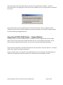
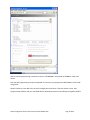
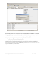
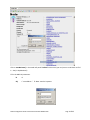
USERS GUIDE SNAP 2.2 Migration Guide Transitioning from Version 2.1 © 2009 Synapse, All Rights Reserved. All Synapse products are patent pending. Synapse, the Synapse logo, SNAP, and Portal are all registered trademarks of Synapse 132 Export Circle Huntsville, Alabama 35806 877-982-7888 Doc# 600023-01A SNAP 2.2 Migration Guide‐v1.0 Document Number 600023‐01A Page 2 of 43 1.0 Introduction ................................................................................................................................................. 7 About This Document (An Important section to read) .................................................................................. 7 Other Important Documentation .................................................................................................................. 7 Summary of New Features............................................................................................................................. 8 Multi‐platform Support.............................................................................................................................. 8 More Visibility into the Mesh Network ..................................................................................................... 8 Finer Granularity ........................................................................................................................................ 8 More Powerful ........................................................................................................................................... 8 More Secure............................................................................................................................................... 8 More Connectivity Options........................................................................................................................ 8 2.0 Upgrading to the Latest Versions................................................................................................................. 9 Upgrading to the latest Portal ....................................................................................................................... 9 Upgrading your SNAP Nodes ....................................................................................................................... 10 Upgrading ZIC2410 SNAP Nodes – Original Method ................................................................................... 11 3.0 Some Important Differences...................................................................................................................... 16 Portal Node Refresh..................................................................................................................................... 16 Low Voltage Detection................................................................................................................................. 16 Demo Builds ................................................................................................................................................. 16 4.0 Multi‐platform Support.............................................................................................................................. 19 Supported Hardware Platforms ................................................................................................................... 19 IO Numbering............................................................................................................................................... 19 How to Use It ........................................................................................................................................... 20 GPIO Numbering .......................................................................................................................................... 20 Additional Features of the Platform Include Files ................................................................................... 21 Using Platform Definitions in SNAPpy Scripts.............................................................................................. 21 Implementation ........................................................................................................................................... 22 Specifying the Platform................................................................................................................................ 23 SNAP 2.2 Migration Guide‐v1.0 Document Number 600023‐01A Page 3 of 43 Example........................................................................................................................................................ 24 Other Uses of the Platform Definition ......................................................................................................... 24 6.0 Supported Platform Details ....................................................................................................................... 25 Synapse RF Engine ....................................................................................................................................... 25 Synapse RF Engine Pin Assignments ........................................................................................................ 26 Freescale MC1321x Chip.............................................................................................................................. 27 MC1321x IO Mapping .............................................................................................................................. 28 Panasonic PAN4555 SNAP Module .............................................................................................................. 29 PAN4555 Module IO Mapping ................................................................................................................. 30 Panasonic PAN4555 (SNAP Engine Form Factor)......................................................................................... 31 Fewer “Wakeup” Pins .............................................................................................................................. 31 Fewer ADC Input Pins............................................................................................................................... 31 You cannot “cheat” and read/write 8 GPIO with a single poke() ............................................................ 31 Two Additional PWM Output Pins ........................................................................................................... 31 getInfo() Differences ................................................................................................................................ 32 For Advanced Users Only ......................................................................................................................... 32 Pin Configuration of a PAN4555 in SNAP Engine Format ........................................................................ 33 PAN4555 GPIO Assignments .................................................................................................................... 34 Panasonic PAN4561 (SNAP Engine Form Factor)......................................................................................... 35 Increased Number of GPIO Pins............................................................................................................... 35 Platform Specific Settings ........................................................................................................................ 35 Platform Specific Hardware Configuration .............................................................................................. 36 ADC Pins ................................................................................................................................................... 36 Low Power Settings (LNA/PA) .................................................................................................................. 36 Default UART remains UART1.................................................................................................................. 37 I2C Emulation vs. Hardware pins ............................................................................................................. 37 Additional PWM Output Pins................................................................................................................... 37 SNAP 2.2 Migration Guide‐v1.0 Document Number 600023‐01A Page 4 of 43 getInfo() Differences ................................................................................................................................ 37 PAN4561 GPIO Assignments .................................................................................................................... 38 Pin Functionality for the PAN4561 Module ............................................................................................. 39 Pin Configuration of a PAN4561 in SNAP Engine Format ........................................................................ 41 California Eastern Labs ZIC2410................................................................................................................... 42 ZIC2410 IO Mapping................................................................................................................................. 42 Separate Analog Input Pins...................................................................................................................... 43 I2C Emulation........................................................................................................................................... 43 SNAP 2.2 Migration Guide‐v1.0 Document Number 600023‐01A Page 5 of 43 SNAP 2.2 Migration Guide‐v1.0 Document Number 600023‐01A Page 6 of 43 1.0 Introduction About This Document (An Important section to read) This manual was written to serve as an interim guide to the key differences between SNAP version 2.1 and SNAP version 2.2. In this document we are focusing mainly on the differences that could become obstacles, if we don’t warn you about them first. Basic features are covered in detail within the 2.1 version of the “SNAP Reference Manual”. The full details related to the new features outlined in this document will be covered in the upcoming 2.2 version of the “SNAP Reference Manual” and the new “SNAP Users Guide”. Other Important Documentation In addition to this document, you will want to refer to the “SNAP 2.2 Release Notes” and the “Portal 2.2 Release Notes”. You should also refer to the existing (2.1) versions of the “SNAP Reference Manual”, the “EK2500 User Guide”, and the “EK2100 User Guide”. Even though these documents have not yet been brought up to date for SNAP 2.2, most of the information in them still applies. Where there are big differences, they are covered in this interim document. All of these documents (as well as new ones going forward) can be downloaded for free from our online support forum at http://forums.synapse‐wireless.com. SNAP 2.2 Migration Guide‐v1.0 Document Number 600023‐01A Page 7 of 43 Summary of New Features The “SNAP 2.2 Release Notes” and “Portal 2.2 Release Notes” go into more detail, but here is a high level view of what has changed since version 2.1. Multi-platform Support Additions to Portal, the SNAP sub‐system, and the SNAPpy scripting language have been made in order to support chips and modules other than those related to the Synapse RF Engine. The details are discussed in a separate section, but the following platforms have been added to the SNAP portfolio: • • • • The ZIC2410 module or chip from CEL The PAN4555 module from Panasonic The PAN4561 module from Panasonic The MC1321x chip from Freescale More Visibility into the Mesh Network Although SNAP Mesh Routing is automatic, and takes place “behind‐the‐scenes” with no user intervention, it is useful to provide more information and more control on “how Mesh routing is working”. Version 2.2 takes several steps forward in this direction such as Traceroute and Topology capture (.dot file creation). Finer Granularity More timer hooks have been added as well as a finer granularity in the duration of sleep() and pulsePin() functionality. More Powerful There were also some changes made to make SNAPpy scripts more capable. These include: • • • • • Tuples Dynamic Strings New built‐in callout() Limited internal radio access Low Voltage Detect More Secure SNAP nodes have been made more secure through the addition of a ‘Lockdown’ mode. More Connectivity Options Version 2.2 allows you to connect to even more types of external devices through built‐in support for: • • • RS‐485 support LCD support Higher radio data rates SNAP 2.2 Migration Guide‐v1.0 Document Number 600023‐01A Page 8 of 43 2.0 Upgrading to the Latest Versions The upgrade process from any 2.x version to version 2.2 is the same as previous versions. You will need to have downloaded the latest Portal (Version 2.2.x) from the Synapse Wireless website. Please see the sections below for notes on upgrading the various software pieces to version 2.2. Upgrading to the latest Portal If you are familiar with upgrading from previous versions of Portal you may want to skip this section as the process is unchanged. After you have downloaded the setup file from the Synapse Wireless website, double‐click to start the installation. If you had any previous version of Portal installed it will first prompt you to uninstall. After the previous Portal version has been in uninstalled the normal setup process should begin. Follow the setup wizard instructions to complete the installation: For further information about the Portal setup wizard, see the EK2100 or EK2500 Users Guide. SNAP 2.2 Migration Guide‐v1.0 Document Number 600023‐01A Page 9 of 43 Upgrading your SNAP Nodes If you are familiar with upgrading from previous versions of SNAP you may want to skip this section as the process has not changed. Starting with Portal version 2.2.22 it is now possible to upgrade ZIC2410 based nodes. If you need to erase the SNAPpy script or default the NV parameters on a ZIC2410 node, please see the section entitled “Upgrading ZIC2410 SNAP Nodes”. Included with the installation of Portal are the necessary Synapse Firmware Image (.SFI) files to upgrade your SNAP nodes. Upgrades use UART1 of the SNAP nodes. This means a connection to the second serial port (usually RS‐232) of the device being upgraded is required. Note that the SNAPstick carrier does not support re‐programming. You must move the node to some other board (like an SN171 Proto Board) in order to upgrade that node’s firmware. First make sure you have an RS232 connection to the node you are upgrading. From Portal’s Options menu, select Firmware Upgrade… The following dialog box will be displayed: Portal will scan your COM ports, and should find the first Synapse device connected to a serial port. If that is not the node you want to upgrade, you can hit the re‐scan button to automatically search for the next serial port with a responding node on it. If Portal does not automatically find your SNAP node, you can manually select the correct COM port. If you have more than one node connected via RS‐232 ports, you may also manually select the correct one instead of repeatedly pressing the button. Next, select the Firmware Image to be used for the upgrade. With the multiple platform support added in version 2.2, there are several more .SFI files included. Be sure to select the correct file for your platform: Platform Filename Freescale MC1321x Panasonic PAN4555 Panasonic PAN4561 MC1321x_*.sfi Synapse RF Engine *SnapV*.sfi CEL ZIC2410 ZIC2410_*.H0* (early releases) ZIC2410_*.sfi (later releases) SNAP 2.2 Migration Guide‐v1.0 Document Number 600023‐01A Page 10 of 43 After choosing the correct firmware image to load, press the Upgrade button to begin. Follow the instructions given in the dialog, which may have you restart (power‐cycle or reset) your device to complete the process. New firmware will be sent to the SNAP node over the serial connection. After the upgrade has been completed you will need to reload any SNAPpy script that was previously on the node. All NV parameters are preserved during the upgrade process. Upgrading ZIC2410 SNAP Nodes – Original Method The original process for ZIC2410 SNAP Nodes uses a different firmware upgrader than for other SNAP nodes. If your version of Portal only includes ZIC2410*.H0* files, use the following instructions. If your version of Portal includes ZIC2410*.sfi files, you can use the normal procedure described above. Using the device programmer, load the banked HEX files into the ZIC2410. Note that “Bank On” is selected, and we don’t need any “Hardware Information”. Connect to UART 1 (this is the USB port on the EVB3 board from CEL) and select the corresponding serial “COM” port for download. Reset the module in ‘ISP’ mode to enter the bootloader, as usual. SNAP 2.2 Migration Guide‐v1.0 Document Number 600023‐01A Page 11 of 43 After successful programming, remember to set the ‘ISP/NORMAL’ switch back to ‘NORMAL’ mode, and reboot. Now that the programming has been completed it is necessary to reprogram the MAC address of the node using Portal. We will continue to use UART1 for the initial configuration with Portal. After the device is reset, start Synapse Portal software and your new SNAP device will be discovered on the COM port assigned to UART1. SNAP 2.2 Migration Guide‐v1.0 Document Number 600023‐01A Page 12 of 43 After connecting, the first thing you need to do is set a unique MAC address for the device. In production, this is typically done by an automated test fixture, after the MAC address bar‐code is scanned. Until it is set, the default MAC is 00:1C:2C:00:00:00:00:FF. This must be changed for proper network operation! For temporary engineering evaluation purposes, assign MAC addresses as follows: “\x00\x1C\x2C\x00\x00\xCE\x00\x01” Increment the last hex‐byte for each successive device, up to 255 (\xFF). Note that the string above is shown in the format required by Portal’s ‘saveNvParam()’ BuiltIn function. This is the function we’ll use to program the MAC address, as shown below: SNAP 2.2 Migration Guide‐v1.0 Document Number 600023‐01A Page 13 of 43 Click on saveNvParam() in the Node Info panel’s BuiltIn function tree (you may have to scroll down to find it – they’re alphabetized.) Fill‐in the MAC NV parameter: id = 2 obj = “ mac address “ Å Note: must be in quotes SNAP 2.2 Migration Guide‐v1.0 Document Number 600023‐01A Page 14 of 43 Next, reboot the device to put the new MAC into effect. You can do this either with a physical HW reset, or click the reboot button in Portal. Ø Finally, refresh Portal’s view of the Network by selecting the “New Configuration” menu item as shown below. Portal will ping the network and find your SNAP devices at their currently assigned MAC addresses. SNAP 2.2 Migration Guide‐v1.0 Document Number 600023‐01A Page 15 of 43 3.0 Some Important Differences As with all new and great things there are some important differences to point out as you use version 2.2 Portal Node Refresh In Portal we have added the option to disable automatic refresh of the node’s information. In version 2.1 when a node was discovered for the first time or when a node became reachable on the network we would automatically refresh his information. In 2.2 in the Preferences it is now possible to turn this feature off. When this feature is disabled it prevents Portal from sending unsolicited RPC calls to nodes it discovers. This feature has been very useful for people who have large SNAP network and want to decrease management traffic. Certain node activities will also be disabled if you choose to disable retrieving the node’s information. For instance, if we do not know the node’s firmware version then we do not know if it supports trace route requests. Until we know this piece of information that option in the toolbar of the Node Info panel will be disabled. Ø The most notable instance of where you might see this is when uploading to a node. If we have not received the node’s version and platform then the upload option will be disabled. The easiest way to retrieve this information from a node is to choose Refresh from the Node Info toolbar. Low Voltage Detection SNAP nodes now have the ability to detect a low voltage condition. When this condition is detected then writing to flash is disabled to prevent corruption. It is important to note that script uploading writes to flash which means a script upload may be prevented due to a low voltage condition. When this occurs you will see the following dialog: Demo Builds If you purchase a demonstration kit or individual nodes from Synapse Wireless or one of its distributors, you have a license for SNAP to run on those purchased products. Customers who are looking to build their own products with radios provided by vendors that run SNAP may be provided with a demo build. These builds are limited in the number of reboots that may be performed before their functionality is reduced. The license status of each node is displayed when clicking on the node in the Node Info panel: SNAP 2.2 Migration Guide‐v1.0 Document Number 600023‐01A Page 16 of 43 Once the reboot limit has been reached the SNAPpy script will be disabled and uploading to the node is not allowed. When this condition occurs the Node Info panel will indicate the new license status: SNAP 2.2 Migration Guide‐v1.0 Document Number 600023‐01A Page 17 of 43 To obtain a permanent license for your SNAP node please contact your sales representative. SNAP 2.2 Migration Guide‐v1.0 Document Number 600023‐01A Page 18 of 43 4.0 Multi-platform Support To support SNAP on a wide variety of hardware configurations, we’ve added two new concepts to SNAPpy. The first new concept is a change in the internal numbering scheme used by the “digital IO” SNAPpy built‐ ins. These include functions like readPin(), writePin(), etc. The second is the introduction of a ‘platform’ parameter that allows for the proper mapping of the digital IO within SNAPpy scripts. Supported Hardware Platforms The following is a list of supported platforms as of the SNAP 2.2 release. Hardware Platform (and associated import) Synapse RFEngine* RFEngine (RFEngine.py) PAN 4555 Module User Defined Option PAN4555 SNAPEngine* PAN4555_SE (PAN4555_SE.py) PAN 4561 Module User Defined Option PAN4561 SNAPEngine* PAN4561_SE (PAN4561_SE.py) MC1321x Chip User Defined Option ZIC2410 Module User Defined Option ZIC2410 Chip User Defined Option * Synapse “SNAP Engine” carrier pin‐out Raw I/O 0‐18 0‐18 0‐18 0‐32 0‐32 0‐32 0‐23 0‐23 The Synapse RF Engine® is a popular wireless device with a particular footprint (pin out) and form factor. (Refer to the SNAP Hardware Reference Manual for more details). We refer to devices that conform to this form factor (or at least the footprint) and are running SNAP as SNAP Engines. Currently you can get SNAP Engines from Synapse (RFE, RFET) and Panasonic (PAN4555 and PAN4561). Although SNAP runs on ZIC2410 chips and modules, there currently is no ZIC2410‐based SNAP Engine. Image: SNAP Engine Form Factor IO Numbering If you are working with SNAP chips or SNAP modules directly, you are working at the level of Raw IO (“IO” for short). This IO numbering scheme follows the internal peripheral model for the chip. For example, if a chip internally has three 8‐bit IO ports labeled “A”, “B”, and “C”, then it has 24 total IO pins (“IOs”), numbered from 0‐23. Port “A” contains IO 0‐7 (0 is LSBit, 7 is MSBit), port “B” contains IO 8‐15, and port “C” contains IO 16‐23. SNAP 2.2 Migration Guide‐v1.0 Document Number 600023‐01A Page 19 of 43 How to Use It As of version 2.2, IO numbering is the “native” numbering scheme for SNAPpy. Built‐in functions like setPinDir(), readPin(), writePin(), pulsePin(), etc. all accept raw IO numbers. To use IO numbering, you don’t have to do anything special. Assuming an LED is hooked up to your first usable IO pin, you could use something like pulsePin(0, 500, True) to blink that LED. However, we strongly recommend against using such “magic numbers” throughout your scripts. Instead define constants with meaningful names, such as: LED_PIN = 0 You can then script actions like pulsePin(LED_PIN, 500, True) You can find more details about the IO available on a particular SNAP Platform by looking in Section 6 of this document. GPIO Numbering This is the second numbering scheme you might find yourself working with. You will notice this is what we use in the majority of the example scripts included with Portal. The footprint of all SNAP Engines defines 19 pin positions as General Purpose IO (GPIO) pins. Numbered from GPIO 0 to GPIO 18, these represent a somewhat abstract concept – they exist only in the context of the SNAP Engine headers. Synapse offers several “demo/prototyping” boards that accept SNAP Engines: • • • • • SN163 Bridge Demonstration Board SN111 End Device Demonstration Board SN171 Proto Board SN132 SNAPstick SN170 Relay Board In addition, several OEMs have put sockets onto their own boards to directly accept Synapse RF Engines (or other pin compatible SNAP Engines). When writing scripts to run on these boards, it is helpful to think in terms of GPIO numbering. Prior to SNAP version 2.2, “GPIO numbering” was also the “native internal numbering”. In other words, in SNAP 2.0/2.1, saying readPin(0) was the same thing as saying readPin(GPIO_0). As of version 2.2, to use GPIO numbering in your scripts simply include the corresponding “platform include file”. For example, if you are writing a script to run on a Synapse SN171 Proto Board, equipped with a PAN4555 SNAP Engine, put the following line near the top of your script: from synapse.PAN4555_SE import * This will correctly define named constants GPIO_0 through GPIO_18 so that you can script actions like: SNAP 2.2 Migration Guide‐v1.0 Document Number 600023‐01A Page 20 of 43 pulsePin(GPIO_1, 500, True) Even then, we strongly recommend that you define meaningful constants instead, doing something like: LED_PIN = GPIO_1 <more script goes here> pulsePin(LED_PIN, 500, True) NOTE – the Synapse RF Engine is a special case, since it is only available as an “RF Engine”. Because of this, it’s mapping of IO numbers to GPIO numbers is “1‐to‐1”. In other words, GPIO_0 = 0, GPIO_1 = 1, etc. To state it another way, nothing has changed in the RFE IO numbering. We still recommend you not hard‐code magic constants, and we have also provided an RFEngine.py “platform include file” as a convenience. Additional Features of the Platform Include Files In addition to defining constants GPIO_0 through GPIO_18, files like PAN4555_SE.py also provides two “lookup tables” (tuples). GPIO_TO_IO_LIST can be used to convert from (you guessed it) GPIO numbers to IO numbers. For example, GPIO_TO_IO_LIST[0] gives you the IO pin number corresponding to GPIO_0. IO_TO_GPIO_LIST can be used to perform the opposite conversion. Just like PAN4555_SE.py covers the PAN4555 based “engine”, there are files for the original RFE (RFEngine.py), and the PAN4561 (PAN4561_SE.py). You can expect this set of files to grow over time, as SNAP is ported to more and more platforms. Using Platform Definitions in SNAPpy Scripts The information in the beginning of this section explains a way to make a script that runs, for example, on a PAN4555 based “engine”, or a script that runs on a PAN4561, or a script that runs on a ZIC2410. But what if you want to write a single script that can work on all three? An approach that would work (but has serious shortcomings) would be to do something like: # NOTE! – This is NOT how you really do it, I am trying to make a point! # Uncomment one of the following lines before uploading # this script into each type of SNAP Node PLATFORM = “RFEngine” #PLATFORM = “PAN4555_SE” #PLATFORM = “PAN4561_SE” #PLATFORM = “something else” <more script goes here> if PLATFORM == “RFEngine”: <code specific to RFE goes here> elif PLATFORM == “PAN4555_SE”: <code specific to PAN4555 SNAP Engine goes here> (and so on) The disadvantage to such an approach is that you have to manually edit the script, save the changes, and upload it to each different type of SNAP node in the network. Let’s look a better approach… SNAP 2.2 Migration Guide‐v1.0 Document Number 600023‐01A Page 21 of 43 Implementation The hypothetical example given above differs only slightly from how the system really works in version 2.2. from synapse.snapsys import * #<- this gives the "platform" definition if platform == "RFEngine": <code specific to RFE goes here> elif platform == "PAN4555_SE": <code specific to PAN4555 SNAP Engine goes here> (and so on) By importing “snapsys” (by adding “from synapse.snapsys import *” to your SNAPpy script), you automatically gain a variable named “platform” that is already filled in with the type of the SNAP node. The platform is retrieved from the node by Portal along with the other information specific to that device (MAC address, Device Image, Firmware Revision, etc.) during the node refresh process. Refer to the earlier section entitled “Portal Node Refresh” for more information. This approach has two advantages: 1) You do not have to manually edit the script (and save it) before uploading it into each different type of SNAP Node. Portal will automatically build the script for the appropriate platform before uploading it. 2) The generated byte‐code (an operation performed by Portal) for all possible hardware platforms is not included in every generated SNAPpy image. Instead, each image includes only the code needed by that platform. This reduces the size of the image, allowing you write larger SNAPpy scripts with greater capabilities. SNAP 2.2 Migration Guide‐v1.0 Document Number 600023‐01A Page 22 of 43 Specifying the Platform The other piece of the puzzle is a new NV Parameter that was just added for version 2.2. NV Parameter #41 is the (user settable) Platform ID for the node. This platform setting is how Portal can select which files are to be conditionally imported. Note: The NV Parameter representing the platform is simply a string that can be set to any unique value. The means you can define your own platform name to identify your own unique hardware. You can see this new setting in the Configuration Parameters dialog box. SNAP 2.2 Migration Guide‐v1.0 Document Number 600023‐01A Page 23 of 43 You can also see this new setting in the Node Info pane. When 2.2 Portal compiles a SNAPpy script (before uploading it), it uses the value of parameter #41 read from the actual node to determine what to set the “platform” variable to. Example One example of this new capability in action is the NewPinWakeupTest.py script (look in your snappyImages subdirectory), and the other SNAPpy scripts it imports (look in the synapse subdirectory under the snappyImages directory). Other Uses of the Platform Definition You could alternatively use the Platform feature to customize SNAPpy images for different variations of your own hardware, or different vendor evaluation boards. NOTE! You do not have to use the GPIO mapping described in this section. If you are only developing on a single type of hardware, you can simply write your script with the specifics of that hardware. However, these concepts outline how you can write scripts that might later be adapted to run on different combinations of hardware. SNAP 2.2 Migration Guide‐v1.0 Document Number 600023‐01A Page 24 of 43 6.0 Supported Platform Details In the remainder of this document, we present some of the low‐level hardware details of each platform (physical environment) you might be writing SNAPpy scripts for. Synapse RF Engine The original SNAP platform… Currently only available in the SNAP Engine form factor, the RF Engine® supports 19 GPIO pins (GPIO_0 to GPIO_18), each with different special abilities. Any of the 19 GPIO can be a digital input, or digital output. Six of the 19 GPIO support a hardware “wakeup” capability, see GPIO 1, 2, 5, 6, 9 and 10 Eight of the 19 GPIO can be used as analog inputs, see GPIO 11‐18 (but notice the order) Four pins support UART 0, see GPIO 3‐6. If you do not need RTS/CTS signals, then GPIO 5 and 6 are available for other usage. Four pins support UART 1, see GPIO 7‐10. If you do not need RTS/CTS signals, then GPIO 9 and 10 are available for other usage. Three pins can optionally be used for CBUS, see GPIO 12‐14. You will also need one “CBUS Chip Select” pin per external CBUS device. Any available GPIO pin can be used for this purpose. Three pins can optionally be used for SPI, see GPIO 12‐14. You will also need one “SPI Chip Select” pin per external SPI device. Any available GPIO pin can be used for this purpose. Two pins can optionally be used for I2C, see GPIO 17 and 18. One pin can optionally be used as a Pulse Width Modulation (PWM) output, see GPIO 0. The seven‐segment LED displays on the SN163 and SN111 demo boards connect to GPIO 13 and 14. On the next page the reference chart from the SNAP Reference Manual is repeated for your convenience. SNAP 2.2 Migration Guide‐v1.0 Document Number 600023‐01A Page 25 of 43 Synapse RF Engine Pin Assignments Pin No. Name Description 1 GND Power Supply 2 GPIO0_TPM1CH2 GPI/O, or Timer1 Channel 2 (ex. PWM out) 3 GPIO1_KBI0 GPI/O, Keyboard Interrupt 4 GPIO2_KBI1 GPI/O, Keyboard Interrupt 5 GPIO3_RX_UART0 GPI/O, or UART0 Data In 6 GPIO4_TX_UART0 GPI/O, or UART0 Data Out 7 GPIO5_KBI4_CTS0 GPI/O, Keyboard Interrupt, or UART0 CTS output 8 GPIO6_KBI5_RTS0 GPI/O, Keyboard Interrupt, or UART0 RTS input 9 GPIO7_RX_UART1 GPI/O, or UART1 Data In 10 GPIO8_TX_UART1 GPI/O, or UART1 Data Out 11 GPIO9_KBI6_CTS1 GPI/O, Keyboard Interrupt, or UART1 CTS output 12 GPIO10_KBI7_RTS1 GPI/O, Keyboard Interrupt, or UART1 RTS input 13 GPIO11_AD7 GPI/O, Analog In 14 GPIO12_AD6 GPI/O, Analog In, CBUS CDATA, or SPI MOSI 15 GPIO13_AD5 GPI/O, Analog In, CBUS CLK, or SPI CLK 16 GPIO14_AD4 GPI/O, or Analog In, CBUS RDATA, or SPI MISO 17 GPIO15_AD3 GPI/O, or Analog In 18 GPIO16_AD2 GPI/O, or Analog In 19 GPIO17_AD1 GPI/O, Analog In, or I2C SDA 20 GPIO18_AD0 GPI/O, Analog In, or I2C SCL 21 VCC Power Supply 22 PTG0/BKDG Background Debug Communications 23 RESET* Module Reset, Active Low 24 GND Power Supply SNAP 2.2 Migration Guide‐v1.0 Document Number 600023‐01A Page 26 of 43 Freescale MC1321x Chip This section applies to you if you are running SNAP on a “raw” MC1321x chip. If you are running SNAP on a Panasonic PAN4555 or PAN4561 module which is based on the MC1321x, please refer instead to one of the following sections. The MC1321x port of SNAP implements 33 “IO” pins (refer to section 4 of this document if you do not understand the difference between an “IO” and a “GPIO”.) The mapping is as follows: PTA0 – PTA7 are mapped to IO 0 – 7. These pins also support “wakeup” capability. PTB0 – PTB7 are mapped to IO 8 – 15. These pins can also be used as analog inputs. PTC0 – PTC7 are mapped to IO 16‐23. PTC0/IO 16 can be used as the UART 1 TX. PTC1/IO 17 can be used as the UART 1 RX. PTC4 is used as the PA_EN (Power Amplifier Enable) signal when enabled by the corresponding Feature Bit (look at the NV Configuration Parameters). PTD2 is mapped to IO 24. This pin can also be used for full PWM. PTD4 – PTD7 are mapped to IO 25 – 28. These 4 pins can do PWM too, but can only vary the duty cycle – the pulse frequency rate is fixed to 1 millisecond, because the underlying hardware timer is providing the “1 millisecond time base” to the rest of the SNAP firmware. PTE0 – PTE1 are mapped to IO 29 – 30. PTE0/IO29 can also be used as the UART 0 TX. PTE1/IO 30 can be used as the UART 0 RX. PTG1 – PTG2 are mapped to IO 31 – 32. The “missing” pins PTD0, PTD1, PTD3, and PTE2 – PTE7 are used inside the MC1321x chip to interface to the built‐in radio. Since they could never be used for external hardware, we did not give them “IO” numbers. Some other hardware mappings: PTA4/IO 4 can be the CTS output for UART 0. PTA5/IO 5 can be the RTS input for UART 0. PTA6/IO 6 can be the CTS output for UART 1. PTA7/IO 7 can be the RTS input for UART 1. The emulated I2C signals are on pins PTB0/IO 8 (SCK) and PTB1/IO 9 (SDA). The emulated SPI signals are on pins PTG2/IO 32 (SCLK), PTG1/IO 31(MOSI), and PTD6/IO 27 (MISO). The following page contains a cross‐reference table for convenience. SNAP 2.2 Migration Guide‐v1.0 Document Number 600023‐01A Page 27 of 43 MC1321x IO Mapping Processor Port Pin SNAPpy IO Processor Port Pin SNAPpy IO PTA0/KBD0 0 PTC1/RxD2 17 PTA1/KBD1 1 PTC2 18 PTA2/KBD2 2 PTC3 19 PTA3/KBD3 3 PTC4 20 PTA4/KBD4 4 PTC5 21 PTA5/KBD5 5 PTC6 22 PTA6/KBD6 6 PTC7 23 PTA7/KBD7 7 PTD2/TPM1CH2 24 PTB0/AD0 8 PTD4/TPM2CH1 25 PTB1/AD1 9 PTD5/TPM2CH2 26 PTB2/AD2 10 PTD6/TPM2CH3 27 PTB3/AD3 11 PTD7/TPM2CH4 28 PTB4/AD4 12 PTE0/TxD1 29 PTB5/AD5 13 PTE1/RxD1 30 PTB6/AD6 14 PTG1/XTAL 31 PTB7/AD7 15 PTG2/EXTAL 32 PTC0/TxD2 16 NOTE – in the above table we are using the chip manufacturer’s naming scheme. Because of this, the first UART is designated with a “1” and the second UART is designated with a “2”. Within SNAPpy, we refer to these as UARTs 0 and 1. SNAP 2.2 Migration Guide‐v1.0 Document Number 600023‐01A Page 28 of 43 Panasonic PAN4555 SNAP Module Because it is based on the Freescale MC1321x chip, the PAN4555 wireless module can also run SNAP. NOTE ‐ If you are using a SNAP Engine based on the PAN4555 module, skip ahead to the next section. This section is for users putting the PAN4555 module directly down on their board. Because the hardware is not in the SNAP Engine form factor, there is no such concept as GPIO. You should write your script using plain “IO” numbering (Refer to section 4 if you don’t know what this means). It is important to note that not all of the MC1321x pins are brought out on the PAN4555 module. The table on the following page summarizes the correspondence between SNAPpy IO, module pin, and the underlying processor pin. SNAP 2.2 Migration Guide‐v1.0 Document Number 600023‐01A Page 29 of 43 PAN4555 Module IO Mapping PAN4555 Module Pin Number PAN4555 Module Pin Name SNAPpy IO Number 1, 9, 17, 25, 31 GND N/A 2 PTB0 8 3 PTB1 9 4 PTB2 10 5 PTB7 15 6 VREF N/A 7 PTA7 7 8 PTA5 5 10 PTA6 6 11 PTG0/BKGD N/A 12 PTG1 31 13 PTG2 32 14 CLKO N/A 15 PTC0 16 16 PTC1 17 18 PTC5 21 19 PTC3 19 20 PTC2 18 21 PTE0 29 22 PTE1 30 23 VDDA N/A 24, 26 VCC N/A 27 RESET N/A 28 PTD6 27 29 PTD4 25 30 PTD2 24 32 EXTANT N/A SNAP 2.2 Migration Guide‐v1.0 Document Number 600023‐01A Page 30 of 43 Panasonic PAN4555 (SNAP Engine Form Factor) In addition to the existing line of Synapse RF Engines, SNAP 2.2 is also available as a SNAP Engine based on Panasonic’s PAN4555 module. Like the RF Engines, this PAN4555 board has 24 pins, and supports 19 GPIO. These two types of modules are largely interchangeable. However, there are a few functional differences to be aware of: Fewer “Wakeup” Pins On a Synapse RF Engine, GPIO pins GPIO1, GPIO2, and GPIO5 can be used to wake the module from “sleep mode”. On a Panasonic PAN4555 Wireless Module, GPIO pins 1, 2, and 5 cannot wake the processor. Note that GPIO pins 1, 2, and 5 can be used as inputs, and they can be monitored. Only the “wakeup” functionality is missing. GPIO pins 6, 9, and 10 can be used to wake from sleep mode on both Synapse RFEs and PAN4555 wireless modules. Fewer ADC Input Pins On a Synapse RF Engine, GPIO pins GPIO11 through GPIO18 can all be used as Analog to Digital Converter (ADC) inputs. On the PAN4555 Wireless Module, only GPIO 11, 16, 17, and 18 support ADC. This means only ADC channels 0, 1, 2, and 7 provide live readings. You cannot “cheat” and read/write 8 GPIO with a single poke() On a Synapse RF Engine, GPIO pins GPIO11 through 18 are all mapped to the same I/O register on the microcontroller. This means these pins can be used to easily implement an 8‐bit wide data bus (see for example script “lcd8bit.py”). On the Panasonic PAN4555, the 4 missing ADC pins (mentioned above) affect this “data bus” as well. You can still write to the 8‐bit wide data register, but only 4 of the pins controlled by that register are actually brought out to the real world. Two Additional PWM Output Pins On a Synapse RF Engine, only GPIO 0 can perform Pulse Width Modulation (PWM). On the PAN4555 Wireless Module, GPIO pins 14 and 15 can also do limited PWM. The PWM limitation on these two pins (GPIO 14 and 15) has to do with the frequency of the pulse that can be modulated. On these two pins, the pulses always occur every 1 millisecond. SNAPpy scripts can affect the width of the pulses, but not the rate at which they occur. Refer to example script PAN4555_ledCycling.py for one example of using these additional PWM pins. If you need a pulse rate different than 1 per millisecond (for example, you are doing servo motor control), you will have to use GPIO 0. SNAP 2.2 Migration Guide‐v1.0 Document Number 600023‐01A Page 31 of 43 getInfo() Differences On a getInfo(0) call, the parameter value of 0 requests a “vendor code”. On a Synapse RFE, getInfo(0) returns 0 (meaning “Synapse”). On a PAN4555, getInfo(0) returns 2 (meaning “Freescale”). On a getInfo(3) call, the parameter value of 3 requests a “platform code”. The PAN4555 returns a value of 5, indicating MC1321x (the chipset the PAN4555 is based on). SNAPpy scripts can use the getInfo() function to adapt themselves to the board they find themselves running on. See also section 5 of this document, where an alternate method is explained. For Advanced Users Only Here are the exact pin changes from a Synapse RFE to a Panasonic PAN4555 when using the SNAPpy GPIO import scheme. SNAPpy GPIO Processor pin used on RFE Processor pin used on PAN4555 1 Port A Bit 0 Port C Bit 3 2 Port A Bit 1 Port C Bit 2 5 Port A Bit 4 Port C Bit 5 12 Port B Bit 6 Port G Bit 1 13 Port B Bit 5 Port G Bit 2 14 Port B Bit 4 Port D Bit 6 15 Port B Bit 3 Port D Bit 4 SNAP 2.2 Migration Guide‐v1.0 Document Number 600023‐01A Page 32 of 43 Pin Configuration of a PAN4555 in SNAP Engine Format Pins that differ from Synapse RF Engines are highlighted in bold. Pin No. Name Description 1 GND Power Supply 2 GPIO0_TPM1CH2 GPI/O or Timer1 Channel 2 (ex. PWM out) 3 GPIO1 GPI/O 4 GPIO2 GPI/O 5 GPIO3_RX_UART0 GPI/O or UART0 Data In 6 GPIO4_TX_UART0 GPI/O or UART0 Data Out 7 GPIO5_CTS0 GPI/O or UART0 CTS output 8 GPIO6_KBI5_RTS0 GPI/O, Keyboard Interrupt, or UART0 RTS input 9 GPIO7_RX_UART1 GPI/O or UART1 Data In 10 GPIO8_TX_UART1 GPI/O or UART1 Data Out 11 GPIO9_KBI6_CTS1 GPI/O, Keyboard Interrupt, or UART1 CTS output 12 GPIO10_KBI7_RTS1 GPI/O, Keyboard Interrupt, or UART1 RTS input 13 GPIO11_AD7 GPI/O or Analog In 14 GPIO12 GPI/O, CBUS CDATA, or SPI MOSI 15 GPIO13 GPI/O, CBUS CLK, or SPI CLK GPI/O, CBUS RDATA, SPI MISO 16 GPIO14_TPM2CH3 or Timer2 Channel 3 (ex. limited PWM out) 17 GPIO15_TPM2CH1 GPI/O, or Timer2 Channel 1 (ex. limited PWM out) 18 GPIO16_AD2 GPI/O or Analog In 19 GPIO17_AD1 GPI/O, Analog In, or I2C SDA 20 GPIO18_AD0 GPI/O, Analog In, or I2C SCL 21 VCC Power Supply 22 PTG0/BKDG Background Debug Communications 23 RESET* Module Reset, Active Low 24 GND Power Supply SNAP 2.2 Migration Guide‐v1.0 Document Number 600023‐01A Page 33 of 43 PAN4555 GPIO Assignments (GPIO assignments defined in PAN4555_SE.py) SNAPpy GPIO Processor Port PAN4555 Module Pin SNAPpy IO Num GPIO_0 PTD2/TPM1CH2 30 24 GPIO_1 PTC3/SCL 19 19 GPIO_2 PTC2/SDA 20 18 GPIO_3 PTE1/RxD1 22 30 GPIO_4 PTE0/TxD1 21 29 GPIO_5 PTC5 18 21 GPIO_6 PTA5/KBD5 8 5 GPIO_7 PTC1/RxD2 16 17 GPIO_8 PTC0/TxD2 15 16 GPIO_9 PTA6/KBD6 10 6 GPIO_10 PTA7/KBD7 7 7 GPIO_11 PTB7/AD7 5 15 GPIO_12 PTG1/XTAL 12 31 GPIO_13 PTG2/EXTAL 13 32 GPIO_14 PTD6/TPM2CH3 28 27 GPIO_15 PTD4/TPM2CH1 29 25 GPIO_16 PTB2/AD2 4 10 GPIO_17 PTB1/AD1 3 9 GPIO_18 PTB0/AD0 2 8 SNAP 2.2 Migration Guide‐v1.0 Document Number 600023‐01A Page 34 of 43 Panasonic PAN4561 (SNAP Engine Form Factor) The PAN4561 utilizes the same core processor as the original RFE and PAN4555 (the Freescale HCS08). In fact, the PAN4561 utilizes the same MC13213 integrated IC (HCS08 plus radio front end) as the PAN4555. As such, the PAN4561 will use a firmware version designed for all modules based on the Freescale MC1321x series of chipsets. This same firmware will run on the PAN4555, PAN4561, etc. The version of SNAP software developed for the PAN4561 follows the same GPIO structure of the PAN4555 for the first 18 GPIO pins. However, there are a few functional details to be aware of: Increased Number of GPIO Pins The PAN4561 has a total of 33 available GPIO pins. These include: • • • • 8 Analog‐to‐Digital (ADC) pins 2 UARTs 8 Keyboard Interrupt pins (KBI) 4 Pulse‐Width Modulated (PWM) output pins Platform Specific Settings SNAPpy NV‐Param #41 is used to store the platform name. For this module the name is ‘PAN4561’. This value can be modified by the user. However, this has the potential to affect SNAPpy script functionality. The platform name will normally be set during the initial programming of the module at the factory. SNAPpy NV‐Param #63 stores the trim value for the radio transceiver’s crystal oscillator (not to be confused with the separate trim value related to the HCS08 MCU). If this value is not set, then the radio will be configured to use the default value‐ typically 0x7E (see MC1321x reference manual for details). The trim value will be set during the initial programming of the module at the factory. SNAP feature bits are used to control a number of things, including module specific settings. For the PAN4561 mounted onto a SNAPpy Engine carrier, a feature bit has be used to specify that a power amplifier exists and that this PA will be disabled before the module enters into a sleep state (and re‐enabled upon waking). The 6th bit (0x20) of Non‐Volatile Parameter (NV‐Param) #11 is used to store this particular setting. The appropriate feature bits will be set during initial programming at the factory. This setting has no effect unless the module is mounted on a SNAP Engine carrier board or Pin 52 and 45 are tied together (See following section for details). None of these values will be reset when executing the ‘Factory Default NV Params’ menu option within the Portal software. SNAP 2.2 Migration Guide‐v1.0 Document Number 600023‐01A Page 35 of 43 Platform Specific Hardware Configuration Low‐Noise Amplifier High‐Gain Mode (HGM) => Radio Transceiver GPIO‐ 3: The LNA located on the PAN4561 module supports a high‐gain mode. This can be enabled or disabled by using GPIO‐3 of the MC1321x’s radio transceiver. HGM State GPIO‐3 Enabled High Disabled Low This GPIO pin can be read and/or controlled by using SNAP’s radioPeek() and radioPoke() built‐in functions. This pin is driven high during the startup process when SNAP Feature Bit 5 (0x20) is set. Refer to the reference manual for the MC1321x and PAN4561 for details regarding memory locations and pin behavior. Power Amplifier Enable/Disable (PA_EN) The Power Amplifier located on the PAN 4561 module can be enabled or disabled by manipulating external pin 52. Setting this pin high will enable the Power Amplifier. PA State Pin 52 Enabled High Disabled Low NOTE: When the PAN4561 is mounted onto a SNAP Engine carrier board, pin 52 and pin 45 (SNAPpy Raw IO 20/ PTC4) are connected together. This allows the PA to be enabled/disabled by manipulating SNAPpy IO 20 (PTC4). This pin is driven high during the startup process when SNAP Feature Bit 5 (0x20) is set. ADC Pins 8 ADC (Analog‐to‐Digital) pins are available for use on the PAN 4561. This is like the Synapse line of RF Engines, but dislike the PAN4555 that only brings out 4 ADC pins. Low Power Settings (LNA/PA) The PAN4561 module includes a Low‐Noise Amplifier (for Rx) and Power Amplifier (for Tx). This power amplifier needs to be placed in a disabled mode in order for the entire module to reach low power operation. The SNAP core will disable the PA during the sleep process and will re‐enable once the system has emerged from sleep. The user does not need to take any action. The LNA is set to a high‐gain mode and the PA is enabled by default during startup when feature bit 0x20 is set and module pin 45 is tied to pin 52. SNAP 2.2 Migration Guide‐v1.0 Document Number 600023‐01A Page 36 of 43 Default UART remains UART1 The default UART is still designated as UART1. This is consistent with SNAP ports to other devices. I2C Emulation vs. Hardware pins The hardware I2C pins designated as SCL and SDA are assigned to GPIO pins 1 and 2 respectfully. However, hardware I2C is not currently enabled within the SNAP core. Instead, the pins associated with SNAPs I2C software emulation (GPIO 17 and 18) remain unchanged from the Synapse RFE and PAN4555. Additional PWM Output Pins PWM on GPIO 0, 14, 15, 31, and 32 On a Synapse RF Engine, only GPIO 0 can perform Pulse Width Modulation (PWM). On the PAN4555 Wireless Module, GPIO pins 14 and 15 can also do limited PWM. On the PAN4561 GPIO pins 31 and 32 can also do limited PWM. The PWM limitation on these four pins (GPIO 14, 15, 31, 32) has to do with the frequency of the pulse that can be modulated. On these pins, the pulses occur every 1 millisecond. SNAPpy scripts can affect the width of the pulses, but not the rate at which they occur. If you need a pulse rate different than 1 per millisecond (for example, you are doing servo motor control), you will have to use GPIO 0. Refer to example script PAN4561_ledCycling.py for one example of using some of these additional PWM pins. getInfo() Differences A call to the SNAP function getInfo() with a parameter value of 0 will request a “vendor code”. On a Synapse RFE, getInfo(0) returns 0 (meaning “Synapse”). On a PAN4561, getInfo(0) returns 2 (meaning “Freescale”). On a getInfo(3) call, the parameter value of 3 requests a “platform code”. The PAN4561 returns a value of 5, indicating MC1321x (the chipset the PAN4561 is based on). SNAPpy scripts can use the getInfo() function to adapt themselves to the board they find themselves running on. See also section 5 of this document, where an alternate method is explained. Please refer to the PAN 4561 Product Specification from Panasonic and the MC1321x Reference Manual from Freescale for more information regarding pin and module functionality. SNAP 2.2 Migration Guide‐v1.0 Document Number 600023‐01A Page 37 of 43 PAN4561 GPIO Assignments (GPIO assignments defined in PAN4561_SE.py) Bold indicates the pins that are the same on the PAN 4555 and 4561 SNAPpy GPIO Processor Port PAN4561 Pin SNAPpy IO Num GPIO_0 PTD2/TPM1CH2 6 24 GPIO_1 PTC3/SCL 11 19 GPIO_2 PTC2/SDA 10 18 GPIO_3 PTE1/RxD1 47 30 GPIO_4 PTE0/TxD1 46 29 GPIO_5 PTC5 44 21 GPIO_6 PTA5/KBD5 36 5 GPIO_7 PTC1/RxD2 9 17 GPIO_8 PTC0/TxD2 8 16 GPIO_9 PTA6/KBD6 35 6 GPIO_10 PTA7/KBD7 34 7 GPIO_11 PTB7/AD7 19 15 GPIO_12 PTG1/XTAL 25 31 GPIO_13 PTG2/EXTAL 26 32 GPIO_14 PTD6/TPM2CH3 4 27 GPIO_15 PTD4/TPM2CH1 2 25 GPIO_16 PTB2/AD2 14 10 GPIO_17 PTB1/AD1 13 9 GPIO_18 PTB0/AD0 12 8 GPIO_19 PTA0/KBD0 41 0 GPIO_20 PTA1/KBD1 40 1 GPIO_21 PTA2/KBD2 39 2 GPIO_22 PTA3/KBD3 38 3 GPIO_23 PTA4/KBD4 37 4 GPIO_24 PTB3/AD3 15 11 GPIO_25 PTB4/AD4 16 12 GPIO_26 PTB5/AD5 17 13 GPIO_27 PTB6/AD6 18 14 GPIO_28 PTC4 45 20 GPIO_29 PTC6 43 22 GPIO_30 PTC7 42 23 GPIO_31 PTD5/TPM2CH2 3 26 GPIO_32 PTD7/TPM2CH4 5 28 SNAP 2.2 Migration Guide‐v1.0 Document Number 600023‐01A Page 38 of 43 Pin Functionality for the PAN4561 Module Processor Port PAN4561 SNAPpy SNAPpy Pin IO Num GPIO PTA0/KBD0 41 0 GPIO_19 PTA1/KBD1 40 1 GPIO_20 PTA2/KBD2 39 2 GPIO_21 PTA3/KBD3 38 3 GPIO_22 PTA4/KBD4 37 4 GPIO_23 PTA5/KBD5 36 5 GPIO_6 PTA6/KBD6 35 6 GPIO_9 PTA7/KBD7 34 7 GPIO_10 PTB0/AD0 12 8 GPIO_18 PTB1/AD1 13 9 GPIO_17 PTB2/AD2 14 10 GPIO_16 PTB3/AD3 15 11 GPIO_24 PTB4/AD4 16 12 GPIO_25 PTB5/AD5 17 13 GPIO_26 PTB6/AD6 18 14 GPIO_27 PTB7/AD7 19 15 GPIO_11 PTC0/TxD2 8 16 GPIO_8 PTC1/RxD2 9 17 GPIO_7 PTC2/SDA 10 18 GPIO_2 PTC3/SCL 11 19 GPIO_1 PTC4 45 20 GPIO_28 PTC5 44 21 GPIO_5 PTC6 43 22 GPIO_29 PTC7 42 23 GPIO_30 PTD2/TPM1CH2 6 24 GPIO_0 PTD4/TPM2CH1 2 25 GPIO_15 PTD5/TPM2CH2 3 26 GPIO_31 PTD6/TPM2CH3 4 27 GPIO_14 PTD7/TPM2CH4 5 28 GPIO_32 PTE0/TxD1 46 29 GPIO_4 PTE1/RxD1 47 30 GPIO_3 PTG1/XTAL 25 31 GPIO_12 PTG2/EXTAL 26 32 GPIO_13 SNAP 2.2 Migration Guide‐v1.0 Document Number 600023‐01A Page 39 of 43 Another view of the same data (PAN4561) PAN4561 Pin Processor Port 2 PTD4/TPM2CH1 25 GPIO_15 3 PTD5/TPM2CH2 26 GPIO_31 4 PTD6/TPM2CH3 27 GPIO_14 5 PTD7/TPM2CH4 28 GPIO_32 6 PTD2/TPM1CH2 24 GPIO_0 8 PTC0/TxD2 16 GPIO_8 9 PTC1/RxD2 17 GPIO_7 10 PTC2/SDA 18 GPIO_2 11 PTC3/SCL 19 GPIO_1 12 PTB0/AD0 8 GPIO_18 13 PTB1/AD1 9 GPIO_17 14 PTB2/AD2 10 GPIO_16 15 PTB3/AD3 11 GPIO_24 16 PTB4/AD4 12 GPIO_25 17 PTB5/AD5 13 GPIO_26 18 PTB6/AD6 14 GPIO_27 19 PTB7/AD7 15 GPIO_11 25 PTG1/XTAL 31 GPIO_12 26 PTG2/EXTAL 32 GPIO_13 34 PTA7/KBD7 7 GPIO_10 35 PTA6/KBD6 6 GPIO_9 36 PTA5/KBD5 5 GPIO_6 37 PTA4/KBD4 4 GPIO_23 38 PTA3/KBD3 3 GPIO_22 39 PTA2/KBD2 2 GPIO_21 40 PTA1/KBD1 1 GPIO_20 41 PTA0/KBD0 0 GPIO_19 42 PTC7 23 GPIO_30 43 PTC6 22 GPIO_29 44 PTC5 21 GPIO_5 45 PTC4 20 GPIO_28 46 PTE0/TxD1 29 GPIO_4 47 PTE1/RxD1 30 GPIO_3 SNAP 2.2 Migration Guide‐v1.0 Document Number 600023‐01A SNAPpy SNAPpy IO Num GPIO Page 40 of 43 Pin Configuration of a PAN4561 in SNAP Engine Format Pins that differ from Synapse RF Engines are highlighted in bold. Pin No. Name Description 1 GND Power Supply 2 GPIO0_TPM1CH2 GPI/O or Timer1 Channel 2 (ex. PWM out) 3 GPIO1 GPI/O 4 GPIO2 GPI/O 5 GPIO3_RX_UART0 GPI/O or UART0 Data In 6 GPIO4_TX_UART0 GPI/O or UART0 Data Out 7 GPIO5_CTS0 GPI/O or UART0 CTS output 8 GPIO6_KBI5_RTS0 GPI/O, Keyboard Interrupt, or UART0 RTS input 9 GPIO7_RX_UART1 GPI/O or UART1 Data In 10 GPIO8_TX_UART1 GPI/O or UART1 Data Out 11 GPIO9_KBI6_CTS1 GPI/O, Keyboard Interrupt, or UART1 CTS output 12 GPIO10_KBI7_RTS1 GPI/O, Keyboard Interrupt, or UART1 RTS input 13 GPIO11_AD7 GPI/O or Analog In 14 GPIO12 GPI/O, CBUS CDATA, or SPI MOSI 15 GPIO13 GPI/O, CBUS CLK, or SPI CLK GPI/O, CBUS RDATA, SPI MISO 16 GPIO14_TPM2CH3 or Timer2 Channel 3 (ex. limited PWM out) 17 GPIO15_TPM2CH1 GPI/O or Timer2 Channel 1 (ex. limited PWM out) 18 GPIO16_AD2 GPI/O or Analog In 19 GPIO17_AD1 GPI/O, Analog In, or I2C SDA 20 GPIO18_AD0 GPI/O, Analog In, or I2C SCL 21 VCC Power Supply 22 PTG0/BKDG Background Debug Communications 23 RESET* Module Reset, Active Low 24 GND Power Supply SNAP 2.2 Migration Guide‐v1.0 Document Number 600023‐01A Page 41 of 43 California Eastern Labs ZIC2410 Currently there is no ZIC‐based SNAP Engine. You will only find SNAP running on CEL chips (ZIC2410) and modules (ZICM2410P0). Because of this, you will only be using “IO” numbering in your SNAPpy scripts. The following table summarizes the IO mapping on the ZIC2410 chip. ZIC2410 IO Mapping Processor Port Pin (P0) SNAPpy IO Processor Port Pin (P1) SNAPpy IO Processor Port Pin (P3) SNAPpy IO P0.0 0 P1.0/RXD1 8 P3.0/RXD0 16 P0.1 1 P1.1/TXD1 9 P3.1/TXD0 17 P0.2 2 P1.2 10 P3.2/INT0 18 P0.3 3 P1.3 11 P3.3/INT1 19 P0.4 4 P1.4 12 P3.4/RTS0/ SPIDI 20 P0.5 5 P1.5 13 P3.5/CTS0/ SPIDO 21 P0.6 6 P1.6 14 P3.6/RTS1/ PWM2/SPICLK 22 P0.7 7 P1.7 15 P3.7/CTS1/ PWM3 23 The same IO numbering scheme applies to the ZICM2410P0 module, but be aware that not all of the chip’s pins are brought out of the module. Specifically, P1.2 (IO 10) and P1.5 (IO 13) are not brought out, and so cannot be used in your module scripts (you can use these pins if you are running SNAP on the bare ZIC2410 chip). SNAP 2.2 Migration Guide‐v1.0 Document Number 600023‐01A Page 42 of 43 Separate Analog Input Pins Unlike many of the SNAP platforms, the analog input pins on the ZIC2410 do not overlap any of the digital IO or other peripherals. You still use the readAdc(channel) SNAPpy built‐in to access the four ACHx channels on the ZIC2410, but there are no corresponding GPIO or IO numbers. I2C Emulation The ZIC2410 has no I2C hardware, but SNAP emulates I2C (I2C master only) in software, using the following two pins: I2C SDA is emulated using P1.3 / SNAPpy IO 11 I2C CLK is emulated using P1.4 / SNAPpy IO 12 Please refer to the CEL ZIC2410 and ZICM2410 data sheets for more information on the pinouts and capabilities of these parts. SNAP 2.2 Migration Guide‐v1.0 Document Number 600023‐01A Page 43 of 43