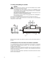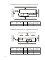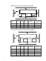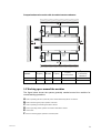
1
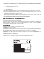
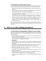
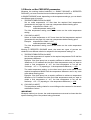
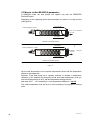
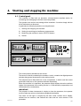
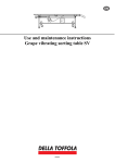
EN Use and Maintenance Manual for Scraped-Surface Wine Coolers and Heat Pumps Rasch 02.02 EN Read all the following safety recommendations very carefully before undertaking any action whatsoever with your machine. FIRST LEARN AND THEN ALWAYS FOLLOW ALL THE SAFETY RECOMMENDATIONS Read these safety recommendations very carefully before installing and using the machine. Also read all the explanatory and warning signs attached to the machine itself. Make sure that they are always easy to read, replacing any damaged or missing signs without delay. Read this manual carefully before using the machine to make sure that you are thoroughly familiar with how it works and all the controls. Never postpone learning this important information until you are already working with the machine. Never allow any unauthorized persons unfamiliar with the equipment to come into the vicinity or operate the machine. Always keep this manual readily available so that anyone taking action on the machine can refer to it. If the machine is sold or transferred to third parties, it is compulsory to hand over all the related technical documentation, use and maintenance EXPLANATION OF THE SYMBOLS Several symbols are used in this manual and on the machine itself to accompany hazard warnings and safety recommendations. These warnings and recommendations serve primarily to ensure the safety of Installers, Technicians and Operators, but also to avoid the machine being damaged. THIS SYMBOL IS USED TO DRAW YOUR ATTENTION TO THE RISK OF FATAL ACCIDENTS, SEVERE INJURIES AND EXTENSIVE DAMAGE IN THE EVENT OF THE SPECIFIED SAFETY MEASURES BEING DISREGARDED. THIS SYMBOL DRAWS ATTENTION TO RISKS OF A GENERAL NATURE. THIS SYMBOL IS USED TO DRAW YOUR ATTENTION TO THE RISK OF FATAL ACCIDENTS, SEVERE INJURIES AND EXTENSIVE DAMAGE IN THE EVENT OF THE SPECIFIED SAFETY MEASURES BEING DISREGARDED. THIS SYMBOL DRAWS ATTENTION TO RISKS DERIVING FROM THE PRESENCE AND USE OF ELECTRICITY. IMPORTANT This word is used to identify paragraphs in the manual containing essential information concerning the machine. Read the related information DEFINITIONS The following are definitions of the individual and legal entities involved in handling and using the machine. OWNWER: In this user manual, the OWNER is the legal representative of the company or body, or the individual, that purchased the machine. The Owner is responsible for ensuring compliance with all the safety requirements specified in the present manual and in the current legislation in the country where the machine is installed. This last aspect is waived if the Owner appoints a plant MANAGER, who thus takes responsibility for implementing the safety recommendations and for compliance with the safety standards relating to the use of the machine and relations with the OPERATOR. INSTALLER: In this user manual, the INSTALLER is the legal representative of the company appointed by the OWNER to install and connect the machine to the hydraulic, electrical and compressed air supply networks (etc.) at the plant. The Installer is responsible for correctly handling and installing the machine in compliance with the recommendations of this manual and with the current legal requirements in the country where the machine is used. OPERATOR: In this user manual, the OPERATOR is the person authorized by the OWNER or MANAGER to take all action on the machine for its usage, adjustment, control and routine servicing, as detailed in this manual (with which Operators must strictly comply, limiting their action to the explicitly allowable procedures). TECHNICIAN: In this user manual, the TECHNICIAN is the person directly authorized by the Manufacturer or, failing this (and entirely under the latter's responsibility), by the Manufacturer's Dealer in the various European Community states outside Italy, to carry out all extraordinary servicing procedures, as well as any adjustments, tests, repairs and replacements of parts proving necessary during the working life of the machine. GENERAL SAFETY RECOMMENDATIONS ! In unloading the machine on arrival, lifting and positioning it at the workplace, and all other handling procedures, comply scrupulously with the recommendations of the relevant section of this manual. Pay particular attention when handling wheel-mounted machines, which have to be moved by hand once they are on the ground. To prevent any risk of crushing, only move the machine by pushing it, never by pulling it, so that nobody can ever come to be in the path of the machine as it moves. Anyone handling the machine must be supervised by another person uninvolved in the procedure, who shall keep a constant watch to ensure that no obstacles or persons get in the machine's way and no other hazardous situations occur. This supervisor must promptly alert the person moving the machine of any hazards so that the machine can be stopped immediately. ! The surface on which the machine slides, like the surface on which it is used, must meet all the essential safety requirements: it must be perfectly horizontal and smooth, with nothing to interfere with the machine's movements. Check in advance to ensure that the whole distance to cover with the machine meets all the above-mentioned requirements. Make sure that the sliding and supporting surfaces have a load-bearing capacity sufficient to withstand the weight of the machine both empty and in use. Any discontinuity in the floor, e.g. expansion joints, grids and manholes, must meet the specified requirements. ! ! ! Never, for any reason whatsoever, lift the machine by any hoisting points other than those indicated. Before the machine is used, it must always be immobilized using the fixing devices provided. The machine must be placed in an area accessible only to the OPERATORS and TECHNICIANS; failing this, it must be protected by a barrier situated at least 2 m away from its outer edge. OPERATORS and TECHNICIANS may access the area where the machine is used providing they are adequately clothed and equipped with the personal protective equipment specified by law (safety shoes, gloves, helmet, etc.). The INSTALLER's personnel, or any visitors, must always be accompanied by an OPERATOR. Unauthorized personnel must never be allowed to remain alone in the vicinity of the machine. The place of installation must be made inaccessible to children. ! OPERATORS shall restrict themselves to taking action on the machine's controls, so they must not open any of the panels, except for the one for accessing the controls (if any). ! The INSTALLER shall restrict himself to taking action on the connections between the plant and the machine, so he must not open any panels, or operate any controls. ! In all handling, usage, servicing or repairs on the machine, it is compulsory to comply with all current safety standards in the country where the machine is used. This applies both to the equipment and to the operating methods adopted. ! Always disconnect the electric power supply before taking any action to install, service, repair or move the machine. This is of fundamental importance to prevent the risk of death, severe injury and extensive damage to the plant. ! In certain stages of normal use, some of the containers comprising the machine are under pressure (e.g. the filter vessel, plenum chamber, erosion-type dosing units, etc.). Never open such containers or remove any components connected to them before you have completely vented said pressure. Venting must be done through the valves provided on the machine specifically for this purpose. ! ! ! ! ! ! ! ! ! ! ! ! ! ! ! Never move the machine during normal working cycles. Before each new working cycle, make sure that any mobile electric connections (power cords, plugs, etc.) are sound and efficient. If they show any signs of damage, repairs must be made only by a specialized TECHNICIAN. Never take any action not mentioned in this manual under your own initiative. Connect the machine to the mains electric power supply according to the recommendations of this manual. Before starting the machine, check the efficiency of the earthing for the electric circuitry and machine frame or structure. Never use power cords of inadequate cross-section or provisional connections, not even briefly, and certainly not in the event of an emergency. Start the machine only after you have made sure of its perfectly safe connection to the systems providing the energy and anything else it needs to function properly (mains electricity and water, compressed gas supply, water drainage network, etc.). Keep a safe distance from any mechanical parts in motion. Immediately report any alarms or the tripping of any automatic machine safety devices to the TECHNICIAN. Never manually reset the machine after an alarm or an automatic safety device has been tripped without first identifying and dealing with the problem that caused them. Never remove the guards over moving parts while the machine is in operation. Before starting the machine, make sure all guards are correctly installed. Routinely perform all the scheduled servicing operations. Dispose of the packaging material for the machine at a suitable landfill, taking particular care over any film and plastic bags, which can expose children to the risk of suffocation. Never release the processing waste deriving from the working process directly into the environment. REGULATIONS FOR USING THE MACHINE IN THE FOODSTUFFS SECTOR The following considerations apply only to machines used with foodstuffs, i.e. destined to come into contact with products for human consumption: The machine in your possession has been designed and built to make it suitable for contact with foodstuffs, and fluids in particular. If in doubt about the intended uses of your machine, refer to the relevant chapter in this manual. ! ! For logistic reasons related to the phases prior to its use (e.g. transport to the user's premises, storage in warehouses, etc.), it is impossible to guarantee the delivery of the machine in conditions suitable to enable its immediate use without an accurate, preliminary sanitization. This is the responsibility of the end user, who may have to comply with any established protocols, e.g. HACCP. DEMOLITION AND DISPOSAL OF THE MACHINE ! At the end of its working life, the machine must be demolished and disposed of. ! THE MACHINE MUST ONLY BE DEMOLISHED AND DISPOSED OF BY ADEQUATELY-TRAINED AND PROPERLY-EQUIPPED PERSONNEL IN COMPLIANCE WITH THE FOLLOWING PROCEDURE. ! 1. Divide the machine into its constituent parts, separating the materials it is made of: ! ! ! ! ! ! ! ! ! mechanical parts (reducers, pump bodies, etc.); metal parts (structure, piping, etc.) electrical parts; rubber parts; plastic and synthetic parts. 2. All resulting materials must be treated and disposed of in accordance with the legal requirements in the country where the machine is used. 3. All components contaminated by oil and oily residues must be considered as special waste and disposed of by authorized consortiums. The same applies to the lubricants that periodically have to be changed. 4. In the event of the machine being placed out of commission, even only temporarily, it must be stored in an area inaccessible to children. All circuit breakers and isolators must be segregated and disconnected. Make a thorough check and release any built-up residual energy, e.g. liquids or gases under pressure inside containers or piping. The machine must also be checked from the static standpoint, to eliminate the risk of any single machine parts moving unexpectedly. THE MANUFACTURER ACCEPTS NO LIABILITY FOR DAMAGE TO PERSONS OR PROPERTY DUE TO THE RE-USE OF SINGLE MACHINE PARTS FOR ANY OTHER THAN THE ORIGINAL PURPOSES OR IN OTHER ASSEMBLY CONDITIONS. INSPECTION OF THE GOODS ON RECEIPT When it is delivered, the machine must be checked by the Customer to identify any signs of damage that it may have suffered in transit and ensure that the machine is complete in every part, as listed on the order form. If there are signs of damage, make an immediate note of the anomalies detected on the transport document (delivery note or CMR), adding the wording “RECEIVED WITH RESERVE DUE TO EVIDENT DAMAGE TO THE MACHINE”. Delivery ex works includes insurance coverage for any damage in accordance with the Italian law 450 of 22.08.1985 "Compensation limit". In the event of complaints, the Customer must be able to produce an adequate photographic documentation of the most obvious damage. GUARANTEE The Manufacturer guarantees the machine for the period indicated in the order form. The GUARANTEE consists exclusively in the replacement or repair, free of charge, of any parts acknowledged as being defective. The GUARANTEE does not cover electrical parts. The GUARANTEE is valid only if all installation and usage instructions have been followed (not only those stated by the Manufacturer, but also those suggested by current practice). The GUARANTEE becomes null and void in the event of any servicing procedures being undertaken by personnel not authorized by the Manufacturer. If the machine alarm sounds or one of the automatic safety devices is tripped, the machine must not be reset manually until the cause of the shutdown has been dealt with. Repeated manual resets can be sufficient reason for the Guarantee to become null and void. The GUARANTEE is valid providing any flaws or defects are reported within eight days of their detection; moreover, the GUARANTEE takes effect providing the use of the machine was suspended immediately after the fault was discovered. AFTER-SALES ASSISTANCE When requesting any information, servicing, or other services, it is essential to specify the SERIAL NUMBER of your machine. It is impossible to provide accurate instructions or schedule servicing measures unless this information is provided. RECOMMENDATIONS FOR PROTECTION AGAINST FREEZING If there is a danger of the ambient temperature dropping to 0°C / 32°F, be sure to empty any liquids (water or product to treat) from all of the machine's hydraulic circuits to prevent ice forming in the piping and damaging parts of the machine. NOTES ........................................................................................................................................................................................................................................ ........................................................................................................................................................................................................................................ ........................................................................................................................................................................................................................................ ........................................................................................................................................................................................................................................ ........................................................................................................................................................................................................................................ ........................................................................................................................................................................................................................................ ........................................................................................................................................................................................................................................ ........................................................................................................................................................................................................................................ ........................................................................................................................................................................................................................................ ........................................................................................................................................................................................................................................ ........................................................................................................................................................................................................................................ ........................................................................................................................................................................................................................................ ........................................................................................................................................................................................................................................ ........................................................................................................................................................................................................................................ ........................................................................................................................................................................................................................................ ........................................................................................................................................................................................................................................ ........................................................................................................................................................................................................................................ ........................................................................................................................................................................................................................................ ........................................................................................................................................................................................................................................ ........................................................................................................................................................................................................................................ ........................................................................................................................................................................................................................................ ........................................................................................................................................................................................................................................ ........................................................................................................................................................................................................................................ IT I circuiti di raffreddamento o riscaldamento chiusi pressurizzati o a pressione atmosferica, devono essere costruiti e utilizzati tenendo presente alcune regole fondamentali per prevenire i fenomeni corrosivi ed i fenomeni incrostanti. 1) Se possibile, il circuito dovrebbe essere costruito utilizzando tubi di un solo metallo oppure con il minor numero possibile di metalli. 2) Nel caso ci siano più metalli, tra di essi dovrebbero essere interposti appositi raccordi in teflon o altro materiale plastico. La lunghezza del raccordo che viene interposto deve essere pari o superiore a 5 volte il diametro della tubazione, con una lunghezza minima di 200 mm. 3) Le tubazioni del circuito devono essere dimensionate in base alle velocità di flusso compatibili con i vari metalli in modo da ridurre al minimo l’abrasione causata dal liquido in movimento. Acciaio al carbonio: Acciaio zincato: Acciaio inox: Leghe di rame: 4) 5) 0,7 - 1,5 m/s 0,7 - 2,0 m/s 0,7 - 2,5 m/s 0,7 - 2,5 m/s Se i circuiti sono costruiti con tubi di metalli diversi, la velocità di flusso dovrebbe variare fra 1 - 1.5 m/s. Con velocità di flusso inferiori a 0.7 m/s si favoriscono i depositi, con velocità di flusso superiori a 1.5 m/s si favorisce la corrosione meccanica dell'acciaio al carbonio che a sua volta si deposita sulle superfici di metalli diversi, nelle parti a più bassa velocità, innescando un fenomeno elettrochimico irreversibile. Tutte le diverse masse metalliche del circuito devono essere collegate a terra elettricamente e la resistenza verso terra deve essere inferiore a 0,2 ohm. Si deve analizzare l'acqua che viene utilizzata nel circuito e verificare, alla temperatura minima e massima di utilizzo, l'indice di Langelier (incrostante o corrosiva) che permette di selezionare il trattamento chimico idoneo ad inibire: • la corrosione chimica • la precipitazione dei sali poco solubili • disperdere o filtrare i solidi sospesi • controllare la crescita microbiologica e algale. EN The positive- or ambient-pressure, closed cooling or heating circuits must be constructed with certain fundamental rules in mind for the prevention of corrosion and fouling phenomena. 1) If possible, the circuit should be made using only pipes made of the same type of metal, or with as few types of metal as possible. 2) If several types of metal are used, special connectors made of Teflon or another plastic material should be inserted between the pipes. The length of each connector inserted between pipes made of different types of metal must be at least 5 times the diameter of the piping concerned, with a minimum length of 200 mm. 3) The circuit piping must be sized so that the flow rates are compatible with the various metals in order to reduce any abrasion caused by the fluid circulating inside the pipes to a minimum. Carbon steel: Galvanized steel: Stainless steel: Copper alloys: 4) 5) 0.7 – 1.5 m/s 0.7 – 2.0 m/s 0.7 – 2.5 m/s 0.7 – 2.5 m/s If the circuits contain pipes made of different metals, the flow rate should range between 1 and 1.5 m/s. A flow rate of less than 0.7 m/s facilitates fouling, while flow rates higher than 1.5 m/s favor mechanical corrosion in carbon steel pipes, which in turn gives rise to fouling on the surfaces of any other metals in the areas where the flow rate is slower, triggering an irreversible electrochemical phenomenon. All the different metal masses in the circuit must be electrically earthed and the ground resistance must be less than 0.2 Ohm. The water used in the circuit must be analyzed and it is essential to check the Langelier index (of fouling potential and corrosivity) at the minimum and maximum working temperatures; this in turn enables you to choose the most suitable type of chemical treatment to: • inhibit chemical corrosion • prevent the precipitation of scarcely soluble salts • decide whether to use dispersion or filtering methods for solids in suspension • control microbiological growth and algae. DE Die geschlossenen unter Druck (oder atmosphärischem Druck) stehenden Kühl- und Heizkreisläufe sind zwecks Vorbeugung von Korrosionserscheinungen und Verkrustungen unter Berücksichtigung folgender Vorgaben herzustellen und einzusetzen. 1) Der Kreislauf sollte sich möglichst nur aus Rohren zusammensetzen, die aus einem einzigen Metall hergestellt wurden. Zumindest jedoch sollte darauf geachtet werden, dass so wenig wie möglich Rohre aus verschiedenartigen Metallen verwendet werden. 2) Sollten dennoch Rohre aus verschiedenartigen Metallen verwendet werden, sind zwischen diesen Anschlussstücke aus Teflon oder einem anderen Kunststoffmaterial zwischenzufügen. Die Länge der zwischenzufügenden Anschlussstücke muss entweder dem Durchmesser des Rohrs entsprechen oder fünf Mal höher als dieser sein. Die Mindestlänge beträgt 200 mm. 3) Die Rohrleitungen des Kreislaufs sind unter Berücksichtigung der Durchflussgeschwindigkeiten auszulegen; diese wiederum müssen mit den verschiedenen Metallen kompatibel sein, damit eine durch die durchströmende Flüssigkeit zurückzuführende Reibung auf ein Minimum reduziert wird. C-Stahl: Verzinkter Stahl: Edelstahl: Kupferlegierungen: 4) 5) 0,7 - 1,5 m/s 0,7 - 2,0 m/s 0,7 - 2,5 m/s 0,7 - 2,5 m/s Setzen sich die Kreisläufe aus Rohren zusammen, die aus verschiedenartigen Metallen hergestellt wurden, muss die Durchflussgeschwindigkeit zwischen 1 - 1.5 m/s variieren. Bei einer Durchflussgeschwindigkeit von weniger als 0.7 m/s wird die Bildung von Ablagerungen begünstigt, bei Durchflussgeschwindigkeiten von mehr als 1.5 m/s hingegen wird die mechanische Korrosion des C-Stahls begünstigt. Der Kohlenstoff lagert sich bei geringen Geschwindigkeiten wiederum an den Flächen der verschiedenen Metalle ab und ruft somit eine irreversible elektrochemische Korrosion hervor. Alle verschiedene metallische Massen des Kreislaufs müssen elektrisch geerdet werden, wobei darauf zu achten ist, dass der Erdwiderstand weniger als 0,2 Ohm beträgt. Das Wasser, das für den Einsatz in den Kreisläufen bestimmt ist, muss zuvor untersucht werden. Ferner ist bei einer betrieblichen Mindest- und Höchsttemperatur der Langelier-Index (Korrosivität des Wassers) zu überprüfen, damit die entsprechende chemische Behandlung bestimmt werden kann und somit Folgendes verhindert wird: • chemische Korrosion. • Ablagerung von schwer lösbaren Salzen. • Dispersion oder Filtration von schwebenden Feststoffen. • Das mikrobiologische Wachstum bzw. das Algenwachstum wird kontrolliert. FR Les circuits de refroidissement ou de chauffage fermés, pressurisés ou sous pression atmosphérique, doivent être construits et utilisés en tenant compte de certaines règles fondamentales afin de prévenir les phénomènes de corrosion et d'entartrage. 1) Si possible, le circuit doit être construit en utilisant des conduites d'un seul métal ou avec le moins grand nombre possible de métaux. 2) En cas de plusieurs métaux, on doit interposer entre eux des raccords spéciaux en téflon ou d'un autre matériau plastique. La longueur du raccord interposé doit être égale ou supérieure à 5 fois le diamètre de la conduite, pour une longueur minimale de 200 mm. 3) Les conduites du circuit doivent être dimensionnées en fonction des vitesses de flux compatibles avec les divers métaux, de manière à réduire au minimum l'abrasion causée par le liquide en mouvement. Acier au carbone : Acier zingué : Acier inox : Alliages de cuivre : 4) 5) 0,7 - 1,5 m/s 0,7 - 2,0 m/s 0,7 - 2,5 m/s 0,7 - 2,5 m/s Si les circuits sont construits avec des conduites constituées de différents métaux, la vitesse de flux doit varier entre 1 et 1,5 m/s. Avec des vitesses de flux inférieures à 0,7 m/s, on favorise les dépôts ; avec des vitesses de flux supérieures à 1,5 m/s, on favorise la corrosion mécanique de l'acier au carbone, dont les produits se déposent, à leur tour, sur les surfaces des métaux différents, dans les parties à vitesse plus faible, ce qui amorce un phénomène électrochimique irréversible. Toutes les différentes masses métalliques du circuit doivent être électriquement reliées à la terre et la résistance à la terre doit être inférieure à 0,2 ohm. On doit analyser l'eau qui est utilisée dans le circuit et vérifier, aux températures minimale et maximale d'utilisation, l'indice de Langelier (entartrage ou corrosion) qui permet de sélectionner le traitement chimique permettant d'inhiber : • la corrosion chimique ; • la précipitation des sels peu solubles ; • l'agglomération des solides en suspension ; • la croissance des microorganismes et des algues. ES Los circuitos de enfriamiento o calentamiento cerrados presurizados o bajo presión atmosférica tienen que ser fabricados y usados recordando algunas reglas básicas para prevenir los fenómenos de corrosión e incrustación. 1) De ser posible, el circuito tiene que ser realizado usando tubos de un solo metal o con el menor número posible de metales diferentes. 2) Si se usan varios metales, entre ellos hay que interponer especiales empalmes de teflón u otro material plástico. La longitud del empalme interpuesto tiene que ser igual o superior a 5 veces el diámetro de la tubería, con una longitud mínima de 200 mm. 3) Las medidas de las tuberías del circuito tiene que ser determinadas de acuerdo con las velocidades de flujo compatibles con los diferentes metales, de manera que se reduzca a lo mínimo la abrasión causada por el líquido en movimiento. Acero al carbono: Acero cincado: Acero inoxidable: Aleaciones de cobre: 4) 5) 0,7 - 1,5 m/s 0,7 - 2,0 m/s 0,7 - 2,5 m/s 0,7 - 2,5 m/s Si los circuitos están realizados con tubos de metales diferentes, la velocidad de flujo tiene que variar entre 1 y 1,5 m/s. Con velocidades de flujo inferiores a 0,7 m/s se favorecen los depósitos; con velocidades de flujo superiores a 1,5 m/s se favorece la corrosión mecánica del acero al carbono, que a su vez se deposita sobre las superficies de los metales diferentes, en las partes donde la velocidad es más baja, y produce un fenómeno electroquímico irreversible. Todas las diferentes masas metálicas del circuito tienen que tener una conexión eléctrica a tierra; la resistencia de la tierra tiene que ser inferior a 0,2 ohmios. Hay que analizar el agua usada en el circuito y comprobar, a la temperatura mínima y máxima de utilización, el índice de Langelier (incrustación o corrosión) que permite seleccionar el tratamiento químico más adecuado para: • inhibir la corrosión química • inhibir la precipitación de sales poco solubles • dispersar o filtrar los sólidos suspendidos • controlar el desarrollo de microbios y algas. ATTENZIONE! PER IL RIEMPIMENTO DI QUESTO APPARECCHIO IMPIEGARE ESCLUSIVAMENTE ACQUA CON LE SEGUENTI CARATTERISTICHE: ! CONTENUTO DI CLORO (Cl) NON SUPERIORE A 20÷30 mg/l - ppm ! SE L’ACQUA È STATA ADDOLCITA LA SUA DUREZZA NON DEVE ESSERE INFERIORE A 7÷10 GRADI FRANCESI (°F), 4÷6 GRADI TEDESCHI (dGH). ! ATTENZIONE ALLE ACQUE PRELEVATE DA POZZI, SOPRATTUTTO NELLE ZONE VICINE AL MARE. L’EVENTUALE SALINITÀ RISULTA CORROSIVA PER L’ACCIAIO INOSSIDABILE. CAUTION! USE ONLY WATER WITH THE FOLLOWING FEATURES TO FILL THIS APPLIANCE: ! CHLORINE (Cl) CONTENT NO GREATER THAN 20-30 mg/l - ppm ! IF THE WATER HAS BEEN SOFTENED, ITS HARDNESS MUST BE NO LESS THAN 7÷10 FRENCH DEGREES (°F), 4÷6 GERMAN DEGREES (dGH). ! BEWARE OF WATER DRAWN FROM WELLS, ESPECIALLY IN AREAS NEAR THE SEA. ANY SALT CONTENT WILL CORRODE THE STAINLESS STEEL. ACHTUNG! FÜR DIE FÜLLUNG DIESER MASCHINE DARF AUSSCHLIESSLICH WASSER MIT FOLGENDEN EIGENSCHAFTEN VERWENDET WERDEN: ! DER CHLORGEHALT (Cl) DARF 20÷30 mg/l ppm NICHT ÜBERSCHREITEN. ! DIE HÄRTE VON ENTHÄRTETEM WASSER DARF NICHT WENIGER ALS 4÷6 DEUTSCHE GRAD (dGH) BZW. 7÷10 FRANZÖSISCHE GRAD (°F) BETRAGEN. ! EIN EVENTUELLER SALZGEHALT IM WASSER, DAS AUS BRUNNEN (INSBESONDERE AUS SOLCHEN, DIE SICH IN MEERESNÄHE BEFINDEN) ENTNOMMEN WURDE, WIRKT KORROSIV AUF EDELSTAHL. ATTENTION ! POUR LE REMPLISSAGE DE CET APPAREIL, N’EMPLOYER QUE DE L’EAU AYANT LES CARACTÉRISTIQUES SUIVANTES : ! TENEUR EN CHLORE (Cl) NE DÉPASSANT PAS 20-30 mg/l - ppm ! SI L’EAU A ÉTÉ ADOUCIE, SA DURETÉ NE DOIT PAS ÊTRE INFÉRIEURE À 7÷10 DEGRÉS FRANÇAIS (°F), 4÷6 DEGRÉS ALLEMANDS (dGH). ! ATTENTION AUX EAUX PROVENANT DE PUITS, SURTOUT DANS LES ZONES PROCHES DE LA MER. L’ÉVENTUELLE SALINITÉ EST CORROSIVE POUR L’ACIER INOXYDABLE. ¡ATENCI N! PARA LLENAR ESTE APARATO USAR SOLAMENTE AGUA CON LAS SIGUIENTES CARACTERÍSTICAS: ! CONTENIDO DE CLORO (Cl) NO SUPERIOR A 20÷30 mg/l - ppm ! SI EL AGUA HA SIDO SUAVIZADA, SU DUREZA NO DEBE SER INFERIOR A 4÷6 GRADOS ALEMANES (dGH), 7÷10 GRADOS FRANCESES (°F). ! TENER CUIDADO CON EL AGUA SACADA DE POZOS, ESPECIALMENTE EN LAS ZONAS CERCANAS AL MAR. LA SALINIDAD ES CAUSA DE CORROSIÓN DEL ACERO INOXIDABLE. ATTENZIONE! DURANTE I PERIODI DI FERMO MACCHINA FARE ATTENZIONE ALLA TEMPERATURA AMBIENTE. SE C'É LA POSSIBILITÀ CHE LA TEMPERATURA SCENDA A 0°C / 32°F BISOGNA PREVENTIVAMENTE SVUOTARE TUTTA L'ACQUA DEL CIRCUITO IDRAULICO PER EVITARE CHE LA FORMAZIONE DI GHIACCIO DANNEGGI I COMPONENTI DELLA MACCHINA. TALE PRECAUZIONE VA ADOTTATA SE NON ESISTONO SISTEMI DI PROTEZIONE COME LIQUIDI ANTIGELO O SISTEMI DI RISCALDAMENTO. CAUTION! WHEN THE MACHINE IS NOT IN USE, PAY ATTENTION TO THE ROOM TEMPERATURE. IF THERE IS A RISK OF THE TEMPERATURE FALLING TO 0°C / 32°F, IT IS ESSENTIAL TO EMPTY ALL THE WATER FROM THE HYDRAULIC CIRCUIT TO AVOID ANY ICE FORMING AND DAMAGING THE MACHINE COMPONENTS. THIS PRECAUTION IS NECESSARY WHENEVER NO OTHER MEANS OF PROTECTION HAVE BEEN PROVIDED, SUCH AS ANTIFREEZE FLUID OR HEATING SYSTEMS. ACHTUNG! WÄHREND DER STILLSTANDZEITEN DER MASCHINE IST AUF DIE RAUMTEMPERATUR ZU ACHTEN. BESTEHT DIE MÖGLICHKEIT, DASS DIE TEMPERATUR AUF 0°C / 32°F) SINKT, IST ZUVOR DAS SICH IM HYDRAULIKKREISLAUF BEFINDLICHE WASSER VOLLKOMMEN AUSZULASSEN, DAMIT SICH BILDENDE EISSCHICHTEN NICHT DIE KOMPONENTEN DER MASCHINE BESCHÄDIGEN. DIESE VORSICHTSMAßNAHME IST IMMER DANN ZU TREFFEN, WENN KEINE FROSTSCHUTZMITTEL ODER HEIZSYSTEME ZUR ANWENDUNG KOMMEN. ATTENTION PENDANT LES PÉRIODES D'ARRÊT MACHINE, FAIRE ATTENTION À LA TEMPÉRATURE AMBIANTE. S'IL SE PEUT QUE LA TEMPÉRATURE DESCENDE À 0°C / 32°F, IL FAUT AU PRÉALABLE VIDANGER TOUTE L'EAU DU CIRCUIT HYDRAULIQUE AFIN D'ÉVITER QUE LA FORMATION DE GLACE N'ENDOMMAGE LES COMPOSANTS DE LA MACHINE. CETTE PRÉCAUTION DOIT ÊTRE ADOPTÉE S'IL N'EXISTE PAS DE SYSTÈMES DE PROTECTION TELS QUE DES LIQUIDES ANTIGEL OU DES DISPOSITIFS DE CHAUFFAGE. ¡ATENCIÓN! DURANTE LAS TEMPORADAS DE PARO DE LA MÁQUINA, HAY QUE PRESTAR ATENCIÓN A LA TEMPERATURA DEL AMBIENTE. SI ES POSIBLE QUE BAJE HASTA 0° C / 32° F, HAY QUE VACIAR PREVIAMENTE TODO EL AGUA DEL CIRCUITO HIDRÁULICO, PARA EVITAR QUE LA FORMACIÓN DE HIELO DAÑE LOS COMPONENTES DE LA MÁQUINA. DICHA PRECAUCIÓN ES NECESARIA SIEMPRE QUE NO EXISTAN SISTEMAS DE PROTECCIÓN ADECUADOS, TALES COMO LÍQUIDOS ANTICONGELANTES O SISTEMAS DE CALEFACCIÓN. Contents 1. 2. 3. 4. 5. 6. General information ..................................................................................................................................3 1.1 1.2 1.3 1.4 1.5 1.6 Introduction ..........................................................................................................................3 Safety recommendations......................................................................................................3 Recommendations concerning these instructions .............................................................5 General description..............................................................................................................5 Allowable uses ......................................................................................................................5 Requirements for use with foodstuffs.................................................................................5 2.1 2.2 2.3 2.4 2.5 2.6 2.7 2.8 Lifting and handling the machine .......................................................................................6 Dimensions of the room where the machine is installed ..................................................6 Working space around the machine ...................................................................................9 Danger zones ......................................................................................................................12 Electric wiring .....................................................................................................................12 Checking the phase balance ..............................................................................................13 Water connections..............................................................................................................13 Preliminary operations before start-up ............................................................................14 Installation requirements .........................................................................................................................5 How to set the working parameters.......................................................................................................14 3.1 Choosing the working method according to the type of plant..............................................14 3.2 How to set the CHILLING parameters ...........................................................................15 3.3 How to set the HEATING parameters ............................................................................16 Starting and stopping the machine.......................................................................................................17 4.1 4.2 4.3 4.4 4.5 Control panel ......................................................................................................................17 Starting and stopping the machine ...................................................................................18 How to set the TEMPERATURE parameters ...............................................................18 Monitoring the machine’s status .......................................................................................19 Alarms .................................................................................................................................20 Servicing operations.................................................................................................................................22 5.1 Servicing the scrapers.........................................................................................................22 5.2 Servicing wine coolers with water-cooled condensers.....................................................23 5.3 Lubrication..........................................................................................................................23 Technical data table.................................................................................................................................24 Diagram of components............................................................................................................. 25 Control panel............................................................................................................................. 26 Rasch 02.02 1 2 Rasch 02.02 1. General information 1.1 Introduction This manual contains all the information you need for the proper use and maintenance of scraped-surface wine coolers and heat pumps with air- and watercooled condensers. The operator must fully understand the information contained in this booklet since proper installation, use and maintenance of the machine are essential to ensure the best results. This manual forms an integral part of the machine, and must therefore be kept with care in a place where it is quickly and easily accessible for consultation. If the system is sold, all the technical documentation supplied with the machine, e.g. user manuals and electrical wiring diagrams, etc., must be forwarded to the new owner. 1.2 Safety recommendations Before taking any action on the scraped-surface wine cooler or heat pump, it is essential for the operator to be able to carry out all the operations described in this manual and to know how to repeat them every time he uses the machine. Always keep the instruction manual readily available when working with the machine. Special attention must be paid to the safety recommendations relating to the use of the machine. The operator’s personal safety depends largely on his understanding and implementing these safety recommendations. The manufacturer accepts no liability for any damage caused directly or indirectly to persons or property as a result of failure to comply with the recommendations of this user manual or the taking of any action other than as described herein. O Routinely check the efficiency of the safety devices (limit switches, pressure switches). O Never remove the safety devices with the machine in operation and never change their settings. O Never take any action on the machine other than as specified in this manual. O For operating problems not considered in this manual, contact your nearest customer support service. In particular, the operator must follow the general safety recommendations set out below: Rasch 02.02 1) On receipt of the machine, it is the customer’s responsibility to make sure that it shows no signs of damage and there are no missing parts. If this is not the case, a complaint must be ledged immediately with the carrier. 2) The machine is tested according to a specific procedure at the manufacturer’s premises. All subsequent tests on the performance of the system must only be done by reproducing and maintaining the same conditions. 3) The machine must be handled, used, serviced and repaired in strict compliance with current accident-prevention requirements in the country where it is installed. This applies both to the equipment 3 involved and to working practices. Never touch condensers unless you are wearing protective gloves. air-cooled 4) All safety requirements must be satisfied as regards the room where the machine is installed and adequate lighting arrangements. 5) The machine must not be installed in an area liable to electromagnetic fields stronger than those specified by the directive 89/339. 6) Any action taken on the machine (installation, maintenance, repairs, shifting) while it is powered may lead to serious and even fatal personal injury. 7) Start the machine only after making sure that it is correctly connected to the system. 8) Make sure of the correct positioning of the guards covering the moving parts before starting the machine. 9) Do not move the machine during a normal working cycle. 10) In the event of the machine signaling a malfunction or alarm, do not perform a manual reset before you have ascertained and overcome the cause of the malfunction. Repeated manual resets may make the guarantee null and void. 11) Turn the machine off in the event of a persistent failure or malfunction. 12) Before starting a new working cycle, make sure the electrical cable connections are undamaged and correctly connected (power cords, plugs etc.). If any damage is detected, do not attempt to repair it yourself; contact an authorized electrician or service center. 13) Do not perform any operation or take any action on the machine that is not described in this manual. 14) Promptly notify the technician of any alarm occurring on the machine. 15) Always disconnect the machine from the mains power supply before carrying out any servicing or repairs. This is essential to prevent any risk of accidental start-ups which may cause injury to persons and/or damage to property. 16) Wear suitable protective equipment (gloves, goggles, etc.) when servicing the machine. 17) Regularly service the machine as specified in this user manual. 18) If the machine is located in a closed room, wear suitable hearing protection. 19) Never use your hands to check for leaks. 20) Never touch the areas marked with temperature warnings (see Figure 2. 4 Rasch 02.02 1.3 Recommendations concerning these instructions Given the numerous variables that can affect the operation of the machine, it is extremely difficult to provide unequivocal recommendations on the best way to handle the various operations. However, once you have gained a little experience on the use of the machine, its great potential for meeting your every need will soon become self-evident. This manual contains the instructions for the standard version and it may be that the machine in your possession does not include certain components illustrated here, or said components may be arranged differently from those illustrated, without this affecting the efficiency and performance of your machine in any way. 1.4 General description The wine coolers and heat pumps are composed of a frame for supporting one or more compressors, the condenser units and the scraper cylinders. The wine coolers are distinguished according to the type of condenser (i.e. aircooled or water-cooled) and are used to cool the product, while the heat pumps can also heat the product. Unlike the air-cooled version, the water-cooled machines have to be connected to a water supply line from a well or a cooling tower. The scraped-surface wine coolers and heat pumps are all similar from the constructional standpoint. The difference between the various dimensions of the models is mainly a matter of different cooling capacities. 1.5 Allowable uses The scraped-surface wine coolers and heat pumps are designed and built for cooling and heating wine or must. No other uses are allowable and the machine must never be used in any operations other than those described in this manual. The machine is not suitable for use in environments with an explosive atmosphere. 1.6 Requirements for use with foodstuffs The machine in your possession has been designed and built in compliance with all current legal requirements concerning its use and contact with foodstuffs destined for human consumption. The end user must nonetheless bear in mind that it is impossible, for reasons relating to its transportation and subsequent installation at the user’s premises, to deliver the press “ready for use” from the hygienic and sanitary standpoint. The user must therefore take all necessary steps to sanitize the equipment in order to comply with all the hygiene standards established by current legislation. All legal requirements concerning the drinking water supply used for washing the cylinder and other operations must also be met (for Italy, Presidential Decree 24 May 1988 n° 236) in order to prevent any risk of contamination. 2. Installation requirements Prior to delivery, the wine coolers undergo stringent testing to ensure their correct operation in different work situations. The following instructions must be scrupulously followed to ensure the proper and safe installation of the machine. Rasch 02.02 5 2.1 Lifting and handling the machine DANGER Before unloading the machine, make sure the installation site is suitable for sustaining the machine’s weight. The installation floor must be able to withstand the COMBINED weight of the machine and the product being processed. Prior to installation, consult the technical data table. Also make sure that the lifting apparatus used to unload and move the machine has a sufficient load-bearing capacity. Never attempt to lift the machine using apparatus that is inadequate or not functioning perfectly. The machine can be lifted and moved with the aid of a fork lift truck (Figure 1). Pay attention to ensure that the forks do not cause strain on any deformable components or electric cables. Figure 1 Wheel-mounted models can easily be moved once they have been placed on the floor. 2.2 Dimensions of the room where the machine is installed For a straightforward and safe use and maintenance of the machine, it is important to allow for the following minimum spaces in the room where the machine is installed (see figures below). In addition to the minimum dimensions specified, the room where the machine is installed must ensure an adequate air circulation, while nonetheless protecting the machine from the weather. Comply with all these requirements, especially for the wheel-mounted wine coolers with air-cooled condensers. 6 Rasch 02.02 Scraped-surface wine cooler and heat pump with air-cooled condenser A D B C MODEL A (mm) B (mm) C (mm) 15,000 600 600 3000 D (mm) D (mm) in normal operation for extraordinary maintenance 600 2600 The distance between the ceiling and the machine must be at least 3000 mm Scraped-surface wine cooler and heat pump with air-cooled condenser A D B C MODEL A (mm) B (mm) C (mm) 20,000 4000 600 40,000 4000 60,000 5000 D (mm) D (mm) in normal operation for extraordinary maintenance 1100 600 2600 600 1100 600 3600 600 1100 600 4000 The distance between the ceiling and the machine must be at least 4000 mm Rasch 02.02 7 Scraped-surface wine cooler with water-cooled condenser A D B C MODEL A (mm) B (mm) C (mm) 15,000 600 600 20,000 600 40,000 60,000 D (mm) D (mm) in normal operation for extraordinary maintenance 1100 600 2600 600 1100 600 2600 600 600 1100 600 3600 600 600 1100 600 4000 The distance between the ceiling and the machine must be at least 2000 mm Scraped-surface wine cooler with air-cooled remote condenser A D B C MODEL A (mm) B (mm) C (mm) 15,000 600 1000 20,000 600 40,000 D (mm) D (mm) in normal operation for extraordinary maintenance 1100 1100 2600 1000 1100 1100 2600 600 1000 1100 1100 3600 60,000 600 1000 1100 1100 4000 80,000 600 1000 1100 1100 3600 120,000 600 1000 1100 1100 4000 The distance between the ceiling and the machine must be at least 2000 mm 8 Rasch 02.02 Scraped-surface wine cooler with air-cooled remote condenser A D B C MODEL A (mm) B (mm) C (mm) 160,000 1100 1000 240,000 1100 1000 D (mm) D (mm) in normal operation for extraordinary maintenance 1100 1100 3600 1100 1100 4000 The distance between the ceiling and the machine must be at least 2000 mm 2.3 Working space around the machine The figure below shows the spaces generally needed around the machine for normal working operations. A Area for operating the valve (if manual) and for mobile and fixed hydraulic connections. B Area for monitoring the proper operation of the fans. C Area for operating and checking the electric devices. D Area for operating valves, hydraulic connections and electric devices E Control area F Area for monitoring proper operation of machine parts Rasch 02.02 9 E D A B Scraped-surface wine cooler with air-cooled condenser Mod. 15,000 Wine cooler scraped-surface condensato ad aria mod. 20,000÷60,000 E A A C Scraped-surface wine cooler with water-cooled condenser 10 Rasch 02.02 E A D F Scraped-surface wine cooler with air-cooled remote condenser mod. 15,000-120,000 F A D F Wine cooler scraped-surface condensato ad aria con condensatore remoto mod. 160,000÷240,000 Rasch 02.02 11 2.4 Danger zones When the machine is in operation, certain areas, i.e. the product inlet and outlet pipes, the compressor head and the related piping (see Figure 2), can reach dangerous temperature levels. To prevent the risk of scalding, never touch these parts without adequate personal protective equipment. Danger zones Figure 2 2.5 Electric wiring All the machines require a three-phase power supply. In compliance with current legislation, it is necessary to install a safety device (not included in the supply) on the power supply line to the electric switchboard. Make sure that the system supplies electrical energy with the characteristics required by the machine, as specified on the nameplate situated near the switchboard. For the scraped-surface wine coolers with air-cooled condensers mod. 15,000 and 20,000, the connection to the mains must be made using the cable, complete with the plug, already fitted at the factory. For all the other models, the connection to the mains power supply must be made at the terminal board situated inside the control panel, on terminals L1, L2, L3 plus the neutral (where applicable) and the earthing connector. IMPORTANT The operator must restrict himself to taking action on the controls; he must never, for any reason, open the switchboard. WARNING The connection to the mains, like all other ordinary and extraordinary action on the wine cooler’s electrical circuitry, must be done by a specialist and the mains power supply must be consistent with the current standards (CEI etc.) and legal requirements. It is important to remember that it is compulsory to earth the machine as well as the electric circuit. Never use cables of inadequate cross section or provisional connections, not even for limited periods of time. 12 Rasch 02.02 2.6 Checking the phase balance Do not operate the electric motors if the voltage unbalance between the phases is greater than 3%. Use the following formula to check the balance: % voltage unbalance = max. voltage shift from mean mean voltage Example: rated mains voltage 400V 3 50 Hz X 100 A B C AB = 409V BC = 398V AC = 396V mean voltage = 409 + 398 + 396 3 = 401V How to calculate the percentage of unbalance: % voltage unbalance = (409 – 401) 401 x 100 = 1.99% This value is acceptable because it is less than the maximum allowable, i.e. 3%. IMPORTANT If the mains voltage has an unbalance greater than 3%, contact the Electricity Board. Operating the machine with a voltage unbalance between the phases greater than 3% makes the GUARANTEE NULL AND VOID. The mains power supply must coincide with the rated value ± 10% 2.7 Water connections The coolers with water-cooled condensers need a water supply line. If a suitable well is available, make the connection as illustrated in Figure 3A; alternatively, if the water is obtained from a cooling tower, connect this to the condenser as shown in Figure 3B A Connection for condensers fed with cooling water from a well. Regulator valve B Connection for condensers fed with water from a cooling tower. Figure 3 Rasch 02.02 13 2.8 Preliminary operations before start-up The wine cooler or heat pump must be properly connected to the various tanks to which it sends the product being processed and also to a number of accessories. - Both fixed (steel pipe) and mobile (flexible plastic conduit) connections can be used. - Rigid connection piping must be fixed independently from the machine so that its weight does not come to bear on the couplings. - Use flexible couplings to connect the rigid pipes in order to prevent the reciprocal transmission of vibrations. - The piping must be compatible with legal requirements concerning the product to be processed (e.g. suitable for beverages or aggressive liquids). - The piping must be suitably sized, with a diameter proportional to the flow rate of the machine and never smaller than the corresponding couplings. - Whatever type of fixed or mobile piping you use, routinely check the couplings for leaks. The tank containing the fluid to chill is connected to coupling 16 while the tank for receiving the chilled product is connected to coupling 19 (see components drawing on page 25. 3. How to set the working parameters 3.1 Choosing the working method according to the type of plant Depending on the version concerned, the scraped-surface wine coolers are suitable either for CHILLING alone or for CHILLING/HEATING wine and must, using two different methods: 1. SINGLE PASSAGE: the fluid flows just once through the scraper cylinder and is cooled to the required temperature. The wine cooler is consequently situated between the tank containing the fluid to cool and the tank for collecting the cooled fluid. IMPORTANT Using this approach, it is essential to use a feed pump of suitable capacity (not provided with the cooler), that enables the fluid to be chilled to the required temperature. Excessively low flow rates cause the wine cooler to stop due to the reaching of the minimum cooling temperature (antifreeze SET POINT, see page 18). 2. REPEATED PASSAGE: the fluid is cooled to the required temperature by repeated passages through the scraper cylinder. In this case, only one tank is involved, connected both to the inlet and to the outlet of the wine cooler. Using this method, you need to use a feed pump with a capacity that ensures a temperature difference between the inlet and the outlet of 2-3°C. With a heat pump in HEATING mode, only the REPEATED PASSAGE method is possible. 14 Rasch 02.02 3.2 How to set the CHILLING parameters Whatever the working method selected, i.e. SINGLE PASSAGE or REPEATED PASSAGE, you have to set the inlet and outlet temperature for the fluid. In SINGLE PASSAGE mode, depending on the temperature settings, you can obtain two different types of process: 1. TARTARIC STABILIZATION (for WINE) Set an outlet temperature 1°C less than the required final temperature (parameter 26, see page 18); never set a temperature below freezing point. Example: temperature to obtain –4°C outlet temperature setting –5°C. The inlet temperature setting must be the same as the outlet temperature setting. 2. CHILLING (for MUST) Select an outlet temperature to 2°C lower than the final temperature required (parameter 26, see page 18); never set a temperature below freezing point. Example: temperature to obtain +15°C outlet temperature setting +13°C. The inlet temperature setting must be the same as the outlet temperature setting. Working in REPEATED PASSAGE mode, the same two types of process are obtained, but a different criterion is adopted for the temperature settings, i.e. 1) TARTARIC STABILIZATION (for WINE) Set the inlet temperature to equate to the required temperature PLUS half the temperature difference. Example: if the feed pump has a capacity sufficient to achieve a temperature difference of 2°C between the inlet and outlet temperatures and you want to obtain a final temperature of –4°C, the inlet temperature to set will be: final temp. –4°C + 1°C (equating to ½ the temperature difference) = –3°C The outlet temperature setting, on the other hand, must be the same as the required temperature MINUS half the temperature difference and in any case never below freezing point. Example: if the feed pump has a capacity sufficient to achieve a temperature difference of 2°C between the inlet and outlet temperatures and you want to obtain a final temperature of –4°C, the inlet temperature to set will be: final temp. –4°C –1°C (equating to ½ the temperature difference) = –5°C 2) CHILLING (for MUST) The temperature setting criteria for must chilling are the same as for the tartaric stabilization of wines. IMPORTANT Whatever method you choose, the outlet temperature must never be lower than the specific freezing point of the product being processed. Rasch 02.02 15 3.3 How to set the HEATING parameters In HEATING mode, the heat pumps can operate only with the REPEATED PASSAGE option. Depending on the operating mode, these machines can warm or cool the product (see Figure 4). Valve CLOSED COOLED PRODUCT OUTLET INLET FOR TO COOL PRODUCT Valve OPEN PRODUCT COOLING CIRCUIT Valve OPEN INLET FOR PRODUCT TO HEAT HEATED OUTLET PRODUCT Valve CLOSED PRODUCT HEATING CIRCUIT Figure 4 Set the inlet temperature to the required temperature minus half the temperature difference (parameter 03). Example: if the feed pump has a capacity sufficient to achieve a temperature difference of 3°C between the heat pump’s inlet and outlet temperatures, and you want a final temperature of 30°C, the inlet temperature setting must be: final temp. 30°C – 1.5°C (equating to ½ the temperature difference) = 28.5°C The outlet temperature must be set at a value equating to the product’s freezing point. 16 Rasch 02.02 4. Starting and stopping the machine 4.1 Control panel This machine is fitted with an electronic microprocessor-controlled device for monitoring and managing the functions and components. The operator can monitor and manage all the machine’s functions simply with the aid of the buttons on this panel. In particular, the following operations can be performed: 1) Starting and stopping the machine 2) Setting the working and antifreeze temperatures 3) Monitoring the machine’s status (STATUS button) 4) Alarms bar set LOW PRESSURE 1 bar set HIGH PRESSURE SET MENÙ STATUS MODE ON/OFF RESET 1 2 bar set LOW PRESSURE 2 LINE bar set HIGH PRESSURE RCU REFRIGERATION CONTROL UNIT The control panel is divided into two sectors. The sector on the left, marked by the numbers 1 and 2, contains the digital pressure switches that govern the pressure in the cooling circuits. The machine can be fitted with one or two compressors, in which case the control panel will contain two or four pressure switches respectively. When the machine is in operation, the pressure switch displays show the real-time values of the pressures in the cooling circuits, i.e. LOW-minimum (evaporation) and HIGH-maximum (condensation). IMPORTANT The purpose of these instruments is simply to show the pressures, the operator must not take any action on the buttons alongside the displays. Rasch 02.02 The sector on the right is occupied by the wine cooler controls and a display, divided into two sections, that indicate the value and the code number of the parameter. 17 4.2 Starting and stopping the machine IMPORTANT POWER ON THE WINE COOLER BY MEANS OF THE MAIN ON/OFF SWITCH (see figure) AT LEAST 8 HOURS BEFORE STARTING THE WORKING CYCLE. This is essential to ensure the proper operation of the wine cooler. Failure to comply with this recommendation can lead to compressor malfunction. After lengthy periods of inactivity or in the case of low ambient temperatures, the preheating time should be extended proportionally. In the water-cooled versions, make sure the water is circulating correctly in the condenser. Wine coolers used in REPEATED PASSAGE mode enable the fermentation and stabilization temperatures to be controlled and maintained. Part of this function is performed by the feed pump (which also has a recirculating function in this case), that stops together with the wine cooler once the temperature setting has been reached. The pump starts again on its own after an interval of about 40 minutes and then operates for about 5 minutes. If an appreciable variation in the temperature of the fluid is detected during this time, the wine cooler also starts again to restore the temperature to the required values. ON/OFF RESET . The compressor will only start after several Press the ON/OFF RESET button minutes because it is timer-controlled. The actual temperature of the fluid to chill is shown on the three-digit display on the left hand side. To switch off the system, press ON/OFF RESET ON/OFF RESET . WARNING It is important to pay the utmost attention during the normal operation of the machine. If it proves necessary to stop the machine immediately for any reason, press the EMERGENCY STOP button. 4.3 How to set the TEMPERATURE parameters The parameters that are displayed when you press the MENU button listed in the table below. DESCRIPTION PARAMETER 02 03 26 92 18 COLD inlet temperature SET POINT (COOLING mode) HOT inlet temperature SET POINT (HEATING mode, for heat pumps only) OUTLET ANTIFREEZE alarm temperature SET POINT PASSWORD (for use only by technical support staff) MENU’ are UNIT OF MEASURE °C °C °C - Rasch 02.02 The procedure for inputting the required values is outlined below. ON/OFF RESET - Turn on the unit by means of the ON/OFF RESET button keyboard. - Press the MENU button - When you press the SET button and off. - If you want to proceed with the selection of other parameters, press the arrow or . keys - again; the value on the left-hand display begins to Press the SET button flash on and off, showing the previously-established inlet temperature set point. - Pressing the arrow keys - once again to memorize the new value or confirm Press the SET button the previous setting if you have made no changes. - Press the MENU button - Press the ON/OFF RESET button MENU’ on the , the right-hand display shows the parameter 02. SET , the right-hand display begins to flash on SET or enables you to change said value. SET MENU’ to abandon the list of parameters. ON/OFF RESET to turn the unit off. 4.4 Monitoring the machine’s status The electronic microprocessor-controlled device also provides useful information on the status of some of the machine’s components. STATUS . To access this information, press the STATUS button The right-hand display immediately shows two digits that identify the code for the element you want to check. To specify the code you require, press the arrow keys or . CODE ON RIGHT-HAND DISPLAY 02 22 40 TYPE OF INFORMATION DISPLAYED COMPRESSOR 1 WORKING HOURS: The display shows how many hours the compressor has been running. If the LED “hx100” comes on, this means that the value of the reading must be multiplied by 100. COMPRESSOR 2 WORKING HOURS (if any): The display shows how many hours the compressor has been running. If the LED “hx100” comes on, this means that the value of the reading must be multiplied by 100. INLET TEMPERATURE PROBE: This indicates the real time value of the temperature detected by the probe installed at the inlet for the fluid to cool. 42 OUTLET TEMPERATURE PROBE: This indicates the real time value of the temperature detected by the probe installed at the outlet for the cooled fluid. Rasch 02.02 19 4.5 Alarms WARNING The connection to the mains, like all other ordinary and extraordinary action on the wine cooler’s electrical circuitry, must be done by a specialist and the mains power supply must be consistent with the current standards (CEI etc.) and legal requirements. It is important to remember that it is compulsory to earth the machine. In the event of any failure immediately after starting the machine or while it is in operation, the left-hand display flashes on and off, indicating a code that enables the cause of the failure to be identified. IMPORTANT If the machine indicates a malfunction or alarm, do not perform a manual reset until you have ascertained and overcome the cause of the malfunction. Repeated manual resets can make the guarantee null and void. The malfunction identification codes are as follows: CODE ON LEFT-HAND DISPLAY TYPE OF RESET E00 Manual SCRAPER AND PRODUCT FEED PUMP MOTOR THERMOMAGNETIC CIRCUIT-BREAKER TRIPPED: disconnect from the mains, then open the switchboard and reset the relay by means of the button provided. E01 Automatic E02 Automatic E03 Manual CIRCUIT 1 HIGH PRESSURE SWITCH. check the power to the fans; check for any obstructions in the condenser (in cooling mode); check the condenser capacity. CIRCUIT 1 LOW PRESSURE SWITCH. check the evaporator capacity (in cooling mode): check for any obstructions in the evaporator battery (heat pump). COMPRESSOR 1 THERMAL RELAY OR KRIWAN PROTECTIVE DEVICE TRIPPED: compressor malfunction (call in technical support service). THERMAL RELAY OR PROTECTOR TRIPPED: If a thermal relay has been tripped, disconnect the power supply and open the switchboard. Reset the thermal relay by pressing the button situated above the relay concerned; If a thermal protector has been tripped, wait for a few minutes to allow for it to cool down E04 Manual Automatic 20 MEANING OF CODE AND WHAT TO DO E05 Automatic E06 Automatic CIRCUIT 1 ANTIFREEZE ALARM TRIPPED: check fluid flow rate to evaporator; check hydraulic pump operation; check suitability of temperature settings. CIRCUIT 1 OUTLET TEMPERATURE PROBE FAILURE: probe malfunction (call in technical support service). Rasch 02.02 E21 Automatic CIRCUIT 2 HIGH PRESSURE SWITCH TRIPPED. check power supply to fans; check for any obstructions in the condenser (in cooling mode); check the condenser capacity. E22 Automatic E23 Manual CIRCUIT 2 LOW PRESSURE SWITCH. check the evaporator capacity (in cooling mode): check for any obstructions in the evaporator battery (heat pump). COMPRESSOR 2 THERMAL RELAY OR KRIWAN PROTECTIVE DEVICE TRIPPED: compressor malfunction (call in technical support service). E25 Automatic E26 Automatic E40 Automatic E41 Manual CIRCUIT 2 ANTIFREEZE ALARM TRIPPED: check fluid flow rate to evaporator; check hydraulic pump operation; check suitability of temperature settings. CIRCUIT 2 OUTLET TEMPERATURE PROBE FAILURE: probe malfunction (call in technical support service). INLET TEMPERATURE PROBE FAILURE: probe malfunction (call in technical support service). COMPRESSOR 1 OR 2 (if any) OIL PRESSURE SWITCH TRIPPED: press the plastic pin on the pressure switch on compressor 1 or 2, then switch the machine off ON/OFF RESET and on again with the button. If the compressor fails to start again after resetting, wait for a few minutes and then press the pin again. Rasch 02.02 21 5. Servicing operations To ensure a continuous and trouble-free use of the machine, the operator must follow a few simple rules that will guarantee optimal, lasting results. WARNING Pay great attention when using liquids for the manual cleaning of the machine. Before aiming a jet of water against any part of the machine, make sure that it has been disconnected from the mains power supply. WARNING Before starting any maintenance on the inside or outside of the machine, be sure to disconnect the mains power supply to avoid any accidental start-ups while the operator is near the machine. 5.1 Servicing the scrapers When the scraper cylinder 11 is dirty, the cooling capacity of the machine declines. It is consequently important - every two full working days, or as necessary - to accurately wash the cylinder using a solution of water and 3% caustic soda (NaOH). Example: use 3 kg of caustic soda every 100 liters of water at a temperature of no more than 35°C; allow the solution to stand inside the machine for 45-60 minutes, so as to eliminate any caked deposits, then empty the cylinder and rinse it thoroughly. Fill the cylinder again with a solution of water and 2% citric acid at a temperature of no more than 35°C; allow to stand for 30 minutes, then rinse thoroughly. Also clean the machine accurately if it is not expected to be used for some time. WARNING The use of corrosive (acid or alkaline) substances can cause operator injury. Comply with the recommended doses. Before use, refer to the manufacturer’s instructions on the package and take all specified precautions. IMPORTANT The water used for washing the machine must be considered as special waste and consequently handled, stocked and disposed of in compliance with current legislation in the country where the machine is installed. 22 Rasch 02.02 5.2 Servicing wine coolers with water-cooled condensers If a wine cooler with a water-cooled condenser is left, even for brief intervals, at ambient temperatures below 0°C it is essential to empty the condenser beforehand. The water normally used for cooling the condenser contains scale deposits that progressively build up on the inside of the heat exchanger pipes, leading to an increase in the maximum pressure. As and when necessary, clean accurately with suitable scale-removing chemicals. 5.3 Lubrication Every 100 working hours approx., grease the scraper shaft bearings at the greasing points provided (see Figure 5). Figure 5 Rasch 02.02 23 4 5 6 19 15 3 7 16 2 1) 2) 3) 4) 5) 6) 7) 8) 9) 10) 11) 12) 13) 14) 15) 16) 17) 19) FIXED WHEELS SCRAPER SHAFT MOTOR PRODUCT OUTLET SIGHTGLASS COMPRESSOR ELECTRIC CONTROL BOARD RUBBER SCRAPER BLADES PRODUCT FEED VALVE (for wine coolers only) REVOLVING WHEELS SCRAPER SHAFT COOLING CAVITY WALL (heating for heat pump versions) SCRAPER CYLINDER LIQUID SEPARATOR EVAPORATOR ASSEMBLY FAN PROTECTION GRID PRODUCT OUTLET VALVE (heat pump versions only) PRODUCT INLET LIQUID RECEIVER PRODUCT OUTLET 11 10 9 8 12 13 5 15 14 11 7 16 Components of scraped-surface wine cooler and heat pump with air-cooled condenser mod. 20.000÷60.000 17 Rasch 02.02 1 25 Electric control board EMERGENCY ALARM RESET PRESENCE RESET MAIN ON/OFF SWITCH PUMP POWER TAKEOFF LINE 0 OFF bar set LOW PRESSURE 1 bar set HIGT PRESSURE SET ME NÙ STATUS MODE ON/OFF RE SET 1 2 bar set LOW PRESSURE 2 1 ON LINE bar set HIGT PRESSURE RCU REFRIGERATION CONTROL UNIT CONTROL PANEL 26 IT I dati contenuti in questa pubblicazione sono forniti a titolo indicativo ed espressi in forma sintetica. La Della Toffola S.p.A potrà apportarvi in qualunque momento eventuali modifiche motivate dalle normali pratiche di sviluppo tecnologico e commerciale, senza peraltro alterare le caratteristiche essenziali del prodotto. Le istruzioni vengono redatte in lingua Italiana e quindi tradotte nella lingua richiesta dal Cliente. Tali traduzioni vengono eseguite con la dovuta diligenza, e fornite poi al Cliente con le riserve di prassi. La Della Toffola S.p.A. non fornisce alcuna garanzia sulle traduzioni realizzate da essa stessa o per suo conto. Viene riconosciuta come ufficiale la versione aggiornata della pubblicazione in lingua Italiana. Per eventuali informazioni il Cliente può contattare la Rete di Assistenza o direttamente la Della Toffola S.p.A. © Della Toffola S.p.A. - Tutti i diritti sono riservati EN The information contained in this publication is provided for use solely as a guideline, and is intended as a brief summary. Della Toffola S.p.A. may make changes at any time based on normal technological and commercial development, without thereby altering the essential features of the product. The instructions are originally written in Italia and then translated into the language requested by the customer. These translations are carried out with due diligence and supplied to the customer with all due reservations. Della Toffola S.p.A. does not offer any guarantee on the translations performed in-house or on its behalf. The updated version of the publication in Italian shall be considered the official document. For any further information, the customer may contact the Service network or Della Toffola S.p.A. Directly. © Della Toffola S.p.A. - All rights reserved DE Die in der vorliegenden Veröffentlichung enthaltenen Daten sind unverbindlich und in gekürzter Form wiedergegeben. Die Firma Della Toffola S.p.A. behält sich das Recht vor, diese Daten jederzeit im Zuge der technischen Weiterentwicklung oder aus kommerziellen Gründen zu modifizieren, ohne allerdings die wesentlichen Eigenschaften des Produkts zu verändern. Die Anleitungen werden in italienischer Sprache verfaßt und anschließend in die vom Kunden gewünschte Sprache übersetzt. Diese Übersetzungen werden mit der gebührenden Sorgfalt ausgeführt und dem Kunden mit den üblichen Vorbehalten zur Verfügung gestellt. Die Firma Della Toffola S.p.A. haftet nicht für die im eigenen Haus oder in ihrem Auftrag ausgeführten Übersetzungen. Offizielle Gültigkeit hat die überarbeitete Version der Veröffentlichung in italienischer Sprache. Für weitere Informationen wenden Sie sich bitte an eine Kundendienststelle oder direkt an Della Toffola S.p.A. © Della Toffola S.p.A. - Alle Rechte vorbehalten. FR Les données figurant dans cette publication sont fournies à titre indicatif et exprimé es en forme synthétique. Della Toffola S.p.A. pourra en tout moment apporter des modifications éventuelles suite au développement technologique et commercial, sans pour cela altérer les caractéristiques essentielles du produit. Les instructions sont rédigées en langue italienne et ensuite traduites dans la langue demandée par le Client. Les traductions sont effectuées avec diligence et fournies au Client sous toutes réserves. Della Toffola S.p.A. ne fournit aucune garantie sur les traductions effectuées à son intérieur ou pour son compte. La version mise à jour de la publication en langue italienne est considérée la version officielle. Pour tout renseignement, le Client peut contacter le Réseau de Service après-vente ou directement la société Della Toffola S.p.A. © Della Toffola S.p.A. - Tous droits réservés. ES Los datos contenidos en esta publicación son sólo indicativos y están expresados de una forma sintética, Della Toffola S.p.A. podrá modificarlos en cualquier momento, debido a normales prácticas de desarrollo tecnológico y comercial, sin que ello altere las características esenciales del producto. Las instrucciones se redactan en italiano y luego se traducen al idioma pedido por el Cliente. Las traducciones se efectúan con el máximo esmero, pero son entregadas al Cliente con las normales reservas de estos casos. Della Toffola S.p.A. no presta ninguna garantía sobre las traducciones realizadas por la empresa misma o por su cuenta. Se reconoce como oficial la versión actualizada de la publicación en italiano. Para más información, el Cliente puede dirigirse a la Red de Asistencia o directamente a Della Toffola S.pA. © Della Toffola S.p.A. - Reservados todos los derechos N° di Matricola - Serial Number Seriennummer - N° de Matricule N° de Matrícula SERVIZIO ASSISTENZA Per qualunque richiesta di informazioni, interventi etc. è sempre necessario comunicare il NUMERO DI MATRICOLA della macchina. Non è possibile fornire istruzioni precise o programmare interventi senza che sia fornito questo dato. Il numero di matricola è anche stampigliato su una apposita targhetta fissata sulla macchina. ASSISTANCE SERVICE For any request regarding information, service, etc., it is always necessary to indicate the SERIAL NUMBER of the machine. It is not possible to provide precise instructions or schedule servicing unless this information is communicated. The serial number is printed on the plate fixed to the machine, too. KUNDENDIENST Bei allen Anfragen um Informationen, Eingriffe usw. stets die SERIENNUMMER der Maschine angeben. Ohne diese Angabe können keine exakten Informationen geliefert und keine Eingriffe geplant werden. Die Seriennummer ist auch dem Typenschild auf der Maschine zu entnehmen. SERVICE ASSISTANCE Pour toute demande d'informations, d'interventions, etc., il faut toujours indiquer le NUMERO DE MATRICULE de la machine. Il est impossible de fournir des instructions précises ou de programmer des interventions sans cette donnée. Le numéro de matricule est estampillé aussi sur la plaquette fixée sur la machine. SERVICIO DE ASISTENCIA Para cualquier solicitud de información, de intervenciones u otros servicios, indicar siempre el NÚMERO DE MATRÍCULA de la máquina. Es imposible suministrar indicaciones precisas o programar intervenciones sin este dato. El número de matrícula se encuentra impreso también en una placa especial aplicada a la máquina. DELLA TOFFOLA S.p.A. Via Feltrina, 72 31040 SIGNORESSA DI TREVIGNANO (TREVISO) ITALY 800-803276 Tel. +39 0423 6772 Internet www.dellatoffola.it e-mail [email protected] Fax +39 0423 670 841 Direzione - Uffici Commerciali Ufficio Amministrazione +39 0423 679 196 Ufficio Tecnico +39 0423 670 491 Ufficio Acquisti