1
Audiometer Calibration
System Manual
Larson Davis
Audiometer Calibration System
Manual
IAUDIT.01 Rev J
Copyright
Copyright 2015 by PCB Piezotronics, Inc. This manual is copyrighted, with all rights reserved. The
manual may not be copied in whole or in part for any use without prior written consent of PCB
Piezotronics, Inc.
Trademarks
PCB is a registered trademark of PCB Piezotronics, Inc. LEMO is a registered trademark of LEMO
SA. LEMO USA is a registered trademark of INTERLEMO HOLDING USA. Microsoft Access
and Microsoft Excel are either registered trademarks or trademarks of Microsoft Corporation in the
United States and/or other countries. B&K BK, and Bruel & Kjaer are registered trademarks of
Bruel & Kjaer Sound & Vibration Measurement A/S.
Disclaimer
The following paragraph does not apply in any state or country where such statements are not
agreeable with local law:
Even though PCB Piezotronics, Inc. has reviewed its documentation, PCB Piezotronics, Inc. makes no
warranty or representation, either expressed or implied, with respect to this instrument and
documentation, its quality, performance, merchantability, or fitness for a particular purpose. This
documentation is subject to change without notice, and should not be construed as a commitment or
representation by PCB Piezotronics, Inc.
This publication may contain inaccuracies or typographical errors. PCB Piezotronics, Inc. will
periodically update the material for inclusion in new editions. Changes and improvements to the
information described in this manual may be made at any time.
Recycling
PCB Piezotronics, Inc. is an environmentally friendly organization and encourages our customers to
be environmentally conscious. When this product reaches its end of life, please recycle the product
through a local recycling center or return the product to:
PCB Piezotronics, Inc.
Attn: Recycling Coordinator
1681 West 820 North
Provo, Utah, USA 84601-1341
where it will be accepted for disposal
Warranty
For warranty information, refer to our Terms and Conditions of Sale on our website at
www.larsondavis.com/TermsConditions.aspx.
Table of Contents
Chapter 1
Welcome to AUDit Audiometer Intelligent Testing
1-1
Formatting Conventions ........................................................................................ 1-2
Unpacking and Inspection ..................................................................................... 1-2
Software Installation ............................................................................................. 1-7
Starting the Software ............................................................................................. 1-8
Chapter 2
Initial Configuration
2-1
Creating a Database .............................................................................................. 2-1
Entering Instrumentation ....................................................................................... 2-3
Preferences .......................................................................................................... 2-13
Chapter 3
Audiometer Test Setup
3-1
Equipment ............................................................................................................ 3-3
Microphones ......................................................................................................... 3-4
Audiometer ............................................................................................................ 3-7
Earphones Screen .................................................................................................. 3-8
Chapter 4
Booth Test or Ambient Noise Level Test
4-1
Equipment for Booth Test ..................................................................................... 4-2
Assembling the system .......................................................................................... 4-3
Connecting the SLM ............................................................................................. 4-5
System Acoustic Calibration ................................................................................. 4-6
Performing a Booth Test ....................................................................................... 4-8
Saving a Booth Test ............................................................................................ 4-10
Suspecting Instrument Noise .............................................................................. 4-11
Chapter 5
Audiometer Test System Assembly
5-1
Audiometer Transducer Test Configurations ........................................................ 5-2
Connect the PC, 824 and PRM902 Preamplifier .................................................. 5-2
AEC100 Coupler Assembly and Calibration ........................................................ 5-4
AEC201 Ear Simulator and Assembly and Calibration ...................................... 5-12
AMC493B Assembly for Testing Bone Vibrators .............................................. 5-21
Chapter 6
Hearing Level Test
6-1
Calibration Main Measurement Screen ................................................................. 6-1
Frequency Test with Earphone Transducers ......................................................... 6-2
IAUDIT.01 Rev I
Chapter 7
Frequency Test
7-1
Calibration Main Measurement Screen .................................................................7-1
Frequency Test with Earphone Transducers ..........................................................7-2
Chapter 8
Linearity Test
8-1
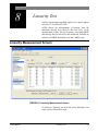
Linearity Measurement Screen ..............................................................................8-1
Chapter 9
Distortion Test
9-1
Harmonic Distortion Measurement Screen ...........................................................9-2
Chapter 10
Pulse Test
10-1
Pulse Measurement Screen ..................................................................................10-2
Chapter 11
Cross Talk Test
11-1
Chapter 12
Frequency Modulation Test
12-1
Chapter 13
Narrow Band Level Test
13-1
Narrow Band Level Test with Earphone Transducers .........................................13-2
Narrow Band Level Test with Speakers ..............................................................13-5
Chapter 14
Broad Band Noise Masking Test
14-1
Broad Band Masking Measurement Screen ........................................................14-1
Chapter 15
Speech Test
15-1
Speech Measurement Screen ...............................................................................15-1
Speech Test with Earphone Transducers .............................................................15-2
Mic Test ...............................................................................................................15-3
Tape/CD A and Tape/CD B Test .........................................................................15-4
Speech Test with Bone Vibrator ..........................................................................15-6
Speech Test with Speakers ..................................................................................15-7
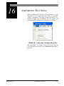
Chapter 16
Audiometer Test Notes
16-1
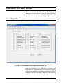
Audiometer Test Notes Screen ............................................................................16-2
Chapter 17
Reports and Data Base Functions
17-1
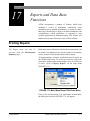
Printing Reports ...................................................................................................17-1
Printing a Certificate ............................................................................................17-4
Exporting Data .....................................................................................................17-7
Stored Measurements Database Functions ..........................................................17-9
Appendix A Glossary
A-1
CHAPTER
1
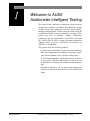
Welcome to AUDit
Audiometer Intelligent Testing
The Larson Davis audiometer calibration system has been
designed for simplicity, portability, and durability. System
weight, volume and component count have been carefully
managed. Measurements for this system are made using the
Larson Davis Model 824 precision sound level meter, which
enables the user to perform complete Audiometer
Calibrations per the requirements of ANSI S3.6-2004 and
IEC 60645-2001 as well as testing Maximum Permissible
Ambient Noise Levels for Audiometric Test Rooms per
ANSI S3.1-1999(R2008).
This system offers the following features:
• A whole range of transducers, their corrections and limits
have been implemented, including: circumaural, supraaural, insert earphones, bone vibrators, and speakers.
• A measurement database search allows quick reference
to previously calibrated audiometers to speed up test
configuration or compare the current test with historical
data
• Extended frequencies can be tested using appropriate
couplers such as the Larson Davis AEC201 coupler and
plates.
AUDit Manual
Welcome to AUDit Audiometer Intelligent Testing
1-1
Formatting Conventions
This manual uses the following format conventions:
• In step-by-step directions, the process (what you do) is
shown in the right column, and the rationale (why you do
it) with other cautions and comments are shown in the
left column.
• User Input: this bold sans-serif typeface indicates
values or selections entered in the software.
• Screen prompts: this bold italic typeface denotes menu
items, prompts, messages, and other textual information
reported by the software.
Unpacking and Inspection
If you have received this manual as part of a complete
Larson Davis audiometer calibration system, this section
will acquaint you with its components. Your order has been
shipped in protective packaging. As most audiometer
calibration hardware must be recertified on an annual basis,
please try to save these packing materials for future use.
Important: If your packaging was
damaged in transit, please contact
your shipping provider for instructions on filing a claim.
1-2
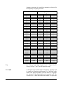
Please compare your system with the following table and
note any discrepancies before contacting your Larson Davis
representative.
Formatting Conventions
AUDit Manual
SYS008
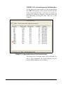
This system has the same components as the SYS009 with
the exception of the AMC493B artificial mastoid.
Part
Description
2575
1 inch precision pressure response microphone, and case
824
Precision integrating sound level meter including
PRM902 1/2 inch preamplifier with 7 pin LEMO connector
PSA027 90-264 Volt to 12 V Power supply.
BAT010 nickel metal hydride AA rechargeable battery pack
CBL006 serial communications cable (with 9 pin D connector)
CBL042 stereo phone plug to dual BNC output cable
I824.01 operator manual
I824.02 training manual
I824.03 firmware upgrade instruction sheet
SWW 824 utility software CD
WS001 - 3 1/2 inch foam windscreen
AM814.06 Neg/Pos AA term Spring Assy for individual AA battery cell use
824-AUD
Audiometric test (internal 824 firmware option)
ADP006
BNC to 1/2 inch preamp thread adaptor with equivalent 47 pF capacitance for
direct input to 824
ADP008
1/2 inch preamp to 1 inch microphone thread adaptor
ADP010
Audiometer earphone adaptor for electrical input to 824
AEC100
6cc coupler (NBS-9-A coupler) with base, coupler, retaining ring, microphone
cap, mass and handle (weight), and pillow
ADP019
1/2 inch MIC TO 1 inch CAL adaptor
CAL250
Precision microphone calibrator with 1 inch opening
I250.1 CAL250 operation manual
CCS007
Weather-tight hard carrying case
DVX011
USB to serial adaptor
EXA010
10 foot microphone extension cable
SWW-AUDIT
Audiometer calibration software including
IAUDit.01 software operator manual and media
AUDit Manual
Unpacking and Inspection
1-3
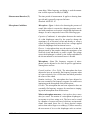
SYS009 with AMC493B
Part
Description
2575
1 inch precision pressure response microphone, and case
824
Precision integrating sound level meter including
PRM902 1/2 inch preamplifier with 7 pin LEMO connector
PSA027 90-264 Volt to 12 V Power supply.
BAT010 nickel metal hydride AA rechargeable battery pack
CBL006 serial communications cable (with 9 pin D connector)
CBL042 stereo phone plug to dual BNC output cable
I824.01 operator manual
I824.02 training manual
I824.03 firmware upgrade instruction sheet
SWW-824.F utility software CD
WS001 - 3 1/2 inch foam windscreen
AM814.06 Neg/Pos AA term Spring Assy for individual AA battery cell use
824-AUD
Audiometric test (internal) 824 firmware option
ADP006
BNC to 1/2 inch preamp thread adaptor with equivalent 47 pF capacitance for
direct input to 824
ADP008
1/2 inch preamp to 1 inch microphone thread adaptor
ADP010
audiometer earphone adaptor for electrical input to 824
AEC100
’6cc coupler’ (NBS-9-A coupler) with base, coupler, retaining ring, microphone cap, mass and handle (weight), and pillow
ADP019
1/2 inch MIC TO 1 inch CAL adaptor
AMC493B
Artificial mastoid coupler and case
IAMC493B.01 AMC493B operator manual
MAE100.55 additional weight ring
CAL250
Precision microphone calibrator with 1 inch opening
I250.1 CAL250 operator manual
CCS007
Weather-tight hard carrying case
DVX011
USB to serial adaptor
EXA010
10 foot microphone extension cable
SWW-AUDIT
Audiometer calibration software including
IAUDit.01 software operator manual and media
1-4
Unpacking and Inspection
AUDit Manual
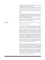
SYS010 with AEC201-A
Part
Description
824
Precision integrating sound level meter including
PRM902 1/2 inch preamplifier with 7 pin LEMO connector
PSA027 90-264 Volt to 12 V Power supply.
BAT010 nickel metal hydride AA rechargeable battery pack
CBL006 serial communications cable (with 9 pin D connector)
CBL042 stereo phone plug to dual BNC output cable
I824.01 operator manual
I824.02 training manual
I824.03 firmware upgrade instruction sheet
SWW-824.F utility software CD
WS001 - 3 1/2 inch foam windscreen
AM814.06 Neg/Pos AA term Spring Assy for individual AA battery cell use
824-AUD
Audiometric test (internal) 824 firmware option
ADP006
BNC to 1/2 inch preamp thread adaptor with equivalent 47 pF capacitance for
direct input to 824
ADP008
1/2 inch preamp to 1 inch microphone thread adaptor
ADP010
audiometer earphone adaptor for electrical input to 824
ADP019
1/2 inch MIC TO 1 inch CAL adaptor
AEC201-A
IEC 60318-1:2009 Ear Simulator with 377A13 microphone
CAL250
Precision microphone calibrator with 1 inch opening
CCS007
Weather-tight hard carrying case
I250.1 CAL250 operator manual
DVX011
USB to serial adaptor
EXA010
10 foot microphone extension cable
SWW-AUDIT
Audiometer calibration software including
IAUDit.01 software operator manual and media
AUDit Manual
Unpacking and Inspection
1-5
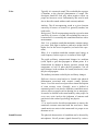
SYS011 with AMC493B and AEC201-A
Part
Description
824
Precision integrating sound level meter including
PRM902 1/2 inch preamplifier with 7 pin LEMO connector
PSA027 90-264 Volt to 12 V Power supply.
BAT010 nickel metal hydride AA rechargeable battery pack
CBL006 serial communications cable (with 9 pin D connector)
CBL042 stereo phone plug to dual BNC output cable
I824.01 operator manual
I824.02 training manual
I824.03 firmware upgrade instruction sheet
SWW-824.F utility software CD
WS001 - 3 1/2 inch foam windscreen
AM814.06 Neg/Pos AA term Spring Assy for individual AA battery cell use
824-AUD
Audiometric test (internal) 824 firmware option
ADP006
BNC to 1/2 inch preamp thread adaptor with equivalent 47 pF capacitance for
direct input to 824
ADP008
1/2 inch preamp to 1 inch microphone thread adaptor
ADP010
audiometer earphone adaptor for electrical input to 824
ADP019
1/2 inch MIC TO 1 inch CAL adaptor
AEC201-A
IEC 60318-1:2009 Ear Simulator with 377A13 microphone
AMC493B
Artificial mastoid coupler and case
IAMC493B.01 AMC493B operator manual
MAE100.55 additional weight ring
CAL250
Precision microphone calibrator with 1 inch opening
I250.1 CAL250 operator manual
CCS007
Weather-tight hard carrying case
DVX011
USB to serial adaptor
EXA010
10 foot microphone extension cable
SWW-AUDIT
Audiometer calibration software including
IAUDit.01 software operator manual and media
Optional Components
• AEC202 2cc Artificial coupler for use with 1/2 inch
microphone for insert earphone measurement.
Microphone not included.
• AEC203 2cc Artificial coupler for 1 inch microphone,
compliant to ANSI S3.7: Microphone not included.
• AEC204 Ear simulator with 1/2 inch microphone.
1-6
Unpacking and Inspection
AUDit Manual
Software Installation
Hardware and Software Requirements
The following table lists the requirements for the installation
and use of the AUDit software for audiometer calibration.
• Operating system: Windows XPTM SP3 (32-bit),
Windows Vista ProfessionalTM SP1 (32-bit), Windows
7TM (32-bit and 64-bit), and Windows 8TM (32-bit and 64bit). AUDit software must be installed using
Administrator rights.
• Network: AUDitTM is not designed to work on a
distributed network from a network drive. However, it
may be operated from a local installation on a computer
connected to a network.
• Communications: One available 9-pin serial
communication port, 9600 baud or greater recommended
or DVX011, USB Adapter to DBM9 interface (824) to
USB port on PC.
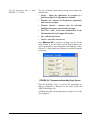
Installing the Software
Place the AUDit CD in your PC and follow the onscreen
instructions. You can accept the default settings on each
screen for proper installation.
FIGURE 1-1 AUDit Icon on desktop
Look for new icon on the PC Desktop.
Getting Help
Contact PCB Piezotronics Technical Support at 888-2583222 (toll free) or +1 716 926-8243 if you encounter any
problems with the installation or use of AUDit software.
AUDit Manual
Software Installation
1-7
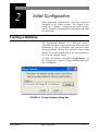
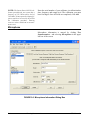
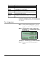
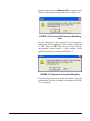
Starting the Software
Step 1
On the PC desktop, double click the AUDit icon to
run the software. If this is the first time you have
used the AUDit software, you will be asked if you
wish to create a new database.
FIGURE 1-2 Create new database Dialog Box
Step 2
Selecting Yes will create a database named
Auditdb.mdb in the default directory. To create a
database later in another directory select No.
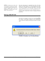
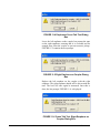
FIGURE 1-3 Could not open database Dialog
Window
Step 3
1-8
Starting the Software
You will be able to enter a database name and
directory in the File, Change Database... menu
item. Press OK to acknowledge the prompt and
display the main menu.
AUDit Manual
CHAPTER
2
Initial Configuration
Before performing a measurement, a few items need to be
configured in the AUDit software. This chapter covers
setting up a database, configuring the system printer,
entering calibration instrumentation information and other
user preferences.
Creating a Database
The measurement database is a Microsoft Access
compatible file which contains information about calibration
instruments, as well as audiometer and booth test results.
During installation, you may have elected to create a blank
database (by default Auditdb.mdb in the current directory).
If so, you may skip this section.
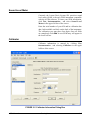
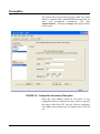
To create a new database, click File, Change Database... in
the AUDit menu to open the Change Database dialog box
then click Browse.
FIGURE 2-1 Change Database Dialog Box
AUDit Manual
Initial Configuration
2-1
The Open dialog box will appear, allowing you to select a
database. To create a database enter a new database name
and select open.
FIGURE 2-2 Open Dialog Box
2-2
Creating a Database
AUDit Manual
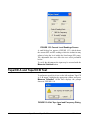
Entering Instrumentation
NOTE: When the desired instrumentation is selected for use with an audiometer measurement, a copy is stored with
the measurement. If changes are later
made to the instrumentation, those
changes will not be reflected in the copy
that is stored with the measurement.
The AUDit audiometer calibration software maintains a list
of the instruments used for calibration. These are normally
certified traceable to NIST (National Institute of Standards
and Technology) measurement standards at specified
intervals. All this information is entered in the
Instrumentation... Screen, shown in FIGURE 2-4.
Click Test, Instrumentation to display the Instrumentation
screen.
FIGURE 2-3 File, Instrumentation Menu
AUDit Manual
Entering Instrumentation
2-3
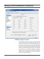
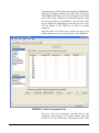
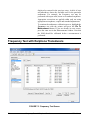
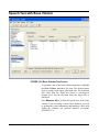
FIGURE 2-4 Instrumentation Screen
Types of instruments are listed in the upper left rectangle.
Currently defined instruments (in this case, sound level
meters) are listed in the rectangle at the lower left. The large
area at the right has fields for model, serial number and other
information for each type of instrument. If your
instrumentation has already been defined for the current
database, skip forward to the “Preferences” section.
If you modify data for an instrument and select Add, then a
new instrument will be created. Update will change the
information for the currently selected instrument. OK must
be selected to commit any changes to the AUDit database.
Selecting Cancel will discard all changes made using Add,
Update, or Delete.
2-4
Entering Instrumentation
AUDit Manual
Sound Level Meter
Currently, the Larson Davis System 824 precision sound
level meter (SLM) is the only SLM instrument compatible
with the AUDit software. To enter your SLM information,
click Test, Instrumentation... and select Sound Level
Meters in the upper left box of the screen.
Enter the serial number of your 824 and its calibration due
date; both available on labels on the back of the instrument.
The calibration year must have four digits. Once all fields
are completed, click Add. A new SLM entry will appear in
the lower left box.
Calibrator
Calibrator information is entered by clicking Test,
Instrumentation... and selecting Calibrators in the upper
left box of the screen.
FIGURE 2-5 Calibrator Information Dialog Box
AUDit Manual
Entering Instrumentation
2-5
NOTE: The Larson Davis CAL250 calibrator provided with your system has a
frequency of 251.2 Hertz and a level of
114.0 dB re 20 micropascals. Output frequency and level are used by the AUDit
the calibration procedure. Entering
incorrect values could lead to measurement errors.
Enter the serial number of your calibrator, its calibration due
date, frequency and output level. The calibration year must
have four digits. Once all fields are completed, click Add.
Microphone
Microphone information is entered by clicking Test,
Instrumentation... and selecting Microphones in the upper
left box of the screen.
FIGURE 2-6 Microphone Information Dialog Box
2-6
Entering Instrumentation
AUDit Manual
Note: The 377A13 requires the
polarization voltage set for Electret
in the 824. In SETUP SLM Settings,
set Transducer to Elctret.
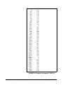
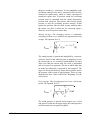
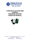
For 2575, 377A13 and 2559 microphones, data can be
imported directly from a .csv file using the import data
button. After importing the .csv file, click OK to save the
imported data to the AUDit database.
For other microphones, frequency response information is
available on the provided calibration chart and can be
entered manually. Some audiometric frequencies may not be
listed exactly: e.g. 200 Hz is listed as 199.53 Hz. If the
frequency labeled in the software is between two
frequencies on the certificate, you may wish to enter an
interpolated value.
FIGURE 2-7 Microphone Frequency Response Information Dialog Box
High frequency and grid cap corrections may not be
necessary if you are not performing the calibration of
extended frequency audiometers.
AUDit Manual
Entering Instrumentation
2-7
Mic
20
25.1
31.6
39.8
50.1
63.1
79.4
100
125.9
158.5
199.5
251.2
316.2
398.1
501.2
631
794.3
1000
1059.3
1122
1188.5
1258.9
1333.5
1412.5
1496.2
1584.9
1678.8
1778.3
1883.7
1995.3
2113.5
2238.7
2371.4
2511.9
2660.7
2818.4
2985.4
3162.3
3349.7
3548.1
3758.4
3981.1
4217
4466.8
4731.5
Larson-Davis 2575 1316
0.43
0.36
0.29
0.23
0.18
0.14
0.1
0.07
0.05
0.03
0.01
0
-0.01
-0.02
-0.03
-0.04
-0.05
-0.06
-0.06
-0.06
-0.06
-0.06
-0.07
-0.07
-0.07
-0.07
-0.07
-0.07
-0.06
-0.06
-0.06
-0.05
-0.04
-0.03
0
0
0.03
0.02
0.05
0.08
0.08
0.12
0.13
0.13
0.13
40.96 4/13/2009
FIGURE 2-8 Example of Imported .CSV File
2-8
Entering Instrumentation
AUDit Manual
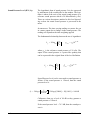
AMC493 Artificial Mastoid
The artificial mastoid is used to calibrate the bone vibrator
used for bone conduction audiometry. Information is entered
by clicking Test, Instrumentation... And selecting Mastoids
in the upper left box of the screen.
The sensitivity of a B&K mastoid is
found on its calibration chart, under
the heading Force Sensitivity
(including cable) and is in units of
mV/N.
Only two types of mastoids are currently supported by
AUDit software: the Larson Davis Model AMC493 and
Bruel & Kjaer 4930 artificial mastoids. Therefore, the
Manufacturer entry is a pull down menu with those two
choices. Enter the manufacturer, model and serial number of
your mastoid and its calibration due date.
Field tests show the sensitivity offset
for the AMC493 to be approximately
12.5 dB.
It is not necessary to enter a sensitivity with the Larson
Davis artificial mastoid. AMC493B information can be
imported directly from a .csv file using Import Data.
The Bruel & Kjaer calibration chart typically has three parts.
Enter values read from Page 2: Frequency Response at
constant dynamic force, using the 5.4 N (black) curve.
AUDit Manual
Entering Instrumentation
2-9
FIGURE 2-9 Mastoids Information Dialog Box
2-10
Entering Instrumentation
AUDit Manual
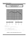
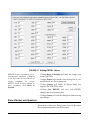
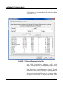
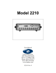
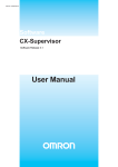
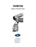
Sample Calibration Report
Artificial Mastoid Test Report: Sensitivity when used on an AEC201
Model: AMC493B Serial Number: 5021
AEC201 Serial Number: 0102
Tested without Black Conical Ring
5
0
-5
Sensitivity (dB)
-10
-15
-20
-25
-30
-35
-40
100
1K
Frequency (Hz)
10K
Mastoid Sensitivity (reference: 20 µPa/µN)
Frequency
(Hz)
Sensitivity
(dB)
Uncertainty
(dB)
Frequency
(Hz)
Sensitivity
(dB)
Uncertainty
(dB)
250
315
400
500
630
750
800
1000
1250
1500
-8.5
-7.0
-6.1
-6.0
-7.3
-8.4
-8.6
-9.5
-9.9
-9.8
0.5
0.6
0.5
0.5
0.6
0.5
0.5
0.6
0.6
0.6
1600
2000
2500
3000
3150
4000
5000
6000
6300
8000
-9.4
-7.9
-6.1
-6.2
-6.9
-10.4
-11.8
-12.9
-13.7
-20.1
0.6
0.8
0.6
0.6
0.7
0.6
0.8
0.6
0.5
0.6
Temperature (°C): 23 ± 1
Relative Humdity (%): 49 ± 5
Static Pressure (kPa): 85.4 ± 2.0 (data corrected to 101.3 ± 3.0)
Uncertainty at ~95% confidence level (k=2)
Tested by Scott Montgomery on 2JUN2011
Test performed at: Larson Davis, a division of PCB Piezotronics, Inc.
1681 West 820 North, Provo, Utah 84601
Tel: 716 684-0001
www.LarsonDavis.com
The results documented in this report relate only to the item(s) tested.
This report may not be reproduced, except in full, without the written approval of the issuer.
Page 1 of 2
FIGURE 2-10 Sample Artificial Mastoid Response chart
AUDit Manual
Entering Instrumentation
2-11
Preamplifier
The Larson Davis System 824 precision sound level meter
(SLM) is supplied with a Model PRM902 preamplifier. To
enter your preamplifier information, click Test,
Instrumentation... And select Preamps in the upper left box
of the screen.
FIGURE 2-11 Preamplifier Information Dialog Box
Enter the serial number etched on the barrel of your
preamplifier and its calibration due date, which is typically
the same as that of the 824. Once all fields are completed,
click Add. A new Preamp entry will appear in the lower left
box.
2-12
Entering Instrumentation
AUDit Manual
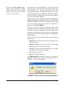
Preferences
This configuration item allows the entry of the calibrating
organization and selection of communication parameters for
the System 824 SLM.
FIGURE 2-12 Test, Set Preferences Menu
AUDit Manual
Preferences
2-13
Two system setup items are available in the rectangular area
at the upper left of the screen as shown in FIGURE 2-13,
Organization and RS232 Port.
FIGURE 2-13 Preferences Dialog Box
Organization
You can also click the Save button on
the test panel when you wish to save
data.
2-14
•
Click in the Name fields to enter information such as
name and address.This information will appear on the
report and calibration certificate.
•
Checking the Show Dialog to save data when changing
test or transducer option will cause the Save dialog box
appear before each change.
•
Checking the Always Save data when changing test or
transducer option will cause the data to be saved automatically for each change without a Save dialog box
prompt.
•
Checking Show warning when Earphone is imcompatible with coupler option will cause a warning message to appear when an incompatibility is detected.
Preferences
AUDit Manual
•
Checking the Show warning when there is no
RETSPL defined for a given frequency option will
cause a warning message to appear before running a test
without RETSPL defined for the frequency to be tested.,
as shown in Figure 2-14.
•
Checking the Display frequencies when there is no
RETSPL will allow the frequencies in the Hearing Level
tests to be displayed without RETSPL being associated
with them.
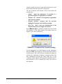
When RETSPL is not defined for the frequencies to be
tested, the message shown in Figure 2-14 appears:
FIGURE 2-14 Frequencies without RETSPL
•
AUDit Manual
•
Click Yes to display all frequencies, including
those with our without RETSPL.
•
Click No to close the dialog box to display only
those frequencies with RETSPL.
•
Click Cancel to uncheck the option to show this
warning message until it is re-checked on the
Preferences dialog box.
Checking the Display "Ears Not Covered" column for
Booth Tests option will display columns in the 125 Hz to
8 kHz, 250 Hz to 8 kHz, and 500 Hz to 8 kHz booth tests
and all of the reports.
Preferences
2-15
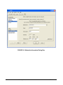
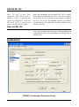
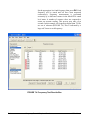
Click RS232 Port to access the screen for RS232
communications port options. Here you may select port
number (COM1 to COM8) and RS232 baud rate (300 to
115kBaud) from pull down menus.
FIGURE 2-15 RS-232 Communications Dialog Box
You have now completed the initial configuration of the
AUDit software. In the next chapter, the system will be
assembled and calibrated to perform an audiometric booth
ambient level test.
2-16
Preferences
AUDit Manual
CHAPTER
3
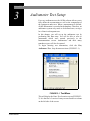
Audiometer Test Setup
For every audiometer test, the AUDit software allows you to
fully define the measurement as well as the components of
the equipment under test. When a measurement is defined,
all this information is recorded in the database. Therefore, an
audiometer system only needs to be defined once, saving a
lot of time in subsequent tests.
In this chapter, you will set up the audiometer test by
performing this data entry. You will be able to refer to
instruments which were entered previously in the
Instrumentation screen. Audiometers and their many
transducer types will also be entered.
To begin entering test information, click the Test,
Audiometer Test... drop down menu item. (FIGURE 3-1).
FIGURE 3-1 Test Menu
This will display the Enter Test Location screen (FIGURE 32). It is the first of a series of entry screens listed in a column
on the left side of the screen.
AUDit Manual
3-1
Test Location
FIGURE 3-2 Test Location Dialog Box
This is where customer information is entered.
Test Location (FIGURE 3-2) contains the following fields:
3-2
•
Customer Name: the customer or company name
•
Location: the location of the audiometer, telephone
number or other information
Audiometer Test Setup
AUDit Manual
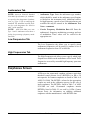
Equipment
NOTE: When the desired instrumentation is selected for use with an audiometer measurement, a copy of the selected
instrumentation is stored with the measurement. If changes are made to the
instrumentation, those changes will not
be reflected in the copy that is stored
with the measurement.
The equipment used to test the audiometer is selected here
from the instrumentation which was entered earlier.
Equipment that has been previously entered into the
instrumentation database is available for selection in these
dialogs. To use a new piece of equipment in a test, first enter
it into the instrumentation database then it can be selected
here.
Mastoid Tab
FIGURE 3-3 Mastoid Selection Tab
The serial number is selectable from a drop down list of the
previously entered serial numbers, which determines the
Model and Manufacturer. The Larson Davis AMC493B and
B&K 4930 artificial mastoids are supported by AUDit. The
AUDit Manual
Equipment
3-3
two boxes at the bottom of the screen are active only for the
appropriate mastoid.
Coupler for Larson Davis Mastoid
Since the Larson Davis AMC493B artificial mastoid
requires corrections based on the coupler with which it is
used, these radio buttons selects either the Larson Davis
Model AEC201 or AEC100 coupler.
Mic used to calibrate the SLM
This box is only enabled with the Bruel & Kjaer artificial
mastoid. It is used to specify which microphone will be used
to calibrate the SLM before using the mastoid. Mastoid and
microphone sensitivities are used to calculate the output
level of the bone vibrator.
Microphones
FIGURE 3-4 Select Microphone Dialog Box
3-4
Audiometer Test Setup
AUDit Manual
Microphones (FIGURE 3-4) allow you to configure the
microphone paired with each coupler.
If a specific coupler will not be used in the audiometer
calibration, no data entry is required.
AEC100 Mic Tab
Select the microphone used with the NBS 9A coupler. This
coupler was originally developed by the National Bureau of
Standards, now called the National Institute of Standards
and Technology (NIST). It is specified in American National
Standard Institute Specifications for Audiometers, S3.6-2004
for calibrating earphones used in audiometry. The Larson
Davis AEC100 artificial ear is designed to meet the
requirements of this standard.
AEC201 Mic Tab
Select the microphone PCB 377A13 used with the AEC201.
This coupler is designed to achieve the characteristics
defined in International Electrotechnical Commission IEC
60318-1:2009 Simulators of Human Head and Ear - Part 1:
Ear Simulator for the calibration of supra-aural and
circumaural earphones. The AEC201 also meets the
requirements of the American National Standard ANSI
S3.7-1995 (R2008) Method for Coupler Calibration of
Earphones (Section 5.4). With the help of a circumaural
adapter plate as described in IEC60318-1:2009 Annex B and
ANSI S3.6-2004 Annex C, the AEC201 may also serve to
calibrate specific high acoustic damping earphones.
AEC202 or AEC203 Mic Tab
Select the microphone used with the HA-1 coupler. This
coupler is described in IEC 60126 (1973-01) IEC reference
coupler for the measurement of hearing aids using
earphones coupled to the ear by means of ear inserts. The
coupler is designed to load the earphone with a specified
acoustic impedance when determining the performance of
air-conduction hearing aids using earphones coupled to the
ear from 200 Hz to 5kHz.
AUDit Manual
Microphones
3-5
AEC204 Mic Tab
Note: 126 and 711 have been
replaced by IEC 60318-4 and -5.
IEC60711 (1981) is canceled and
replaced by IEC60318-4 (2010) and
IEC 60126 (1973) is canceled and
replaced by IEC 60318-5 (2006).
Select the microphone used with the IEC 60711 coupler.
This coupler is described in IEC 60711 (1981-01) Occludedear simulator for the measurement of earphones coupled to
the ear by ear inserts. The standard specifies an occludedear simulator for the calibration of insert earphones from
100 Hz to 10 kHz.
Open Air Mic Tab
Select the microphone used for open air measurements such
as the ambient noise level measurement of the Booth Test, or
speakers tests.
Audiometer
FIGURE 3-5 Audiometer Description Screen
3-6
Audiometer Test Setup
AUDit Manual
The Audiometer Description screen contains information on
the audiometer (or signal generator) under test, while its
transducers are defined in the remaining screens of the setup
items. The Audiometer Description screen is composed of
three different tabs to describe the audiometer and the
frequencies at which it is tested.
AUDit Manual
Audiometer
3-7
Audiometers Tab
NOTE: American National Standard
•
Audiometer Type: Enter the audiometer type number,
which should be stated in the audiometer specifications
or labeled on the instrument itself. Additional suffixes
for high frequency, speech or free field equivalent are not
available but may be entered in the Audiometer Test
Notes... comments.
•
Carrier Frequency Modulation Rate Of: Enter the
audiometer's frequency modulation percentage and rate
of modulation. These values will be verified in the
appropriate test.
S3.6-2004 Specifications for Audiometers specifies the designation of audiometers (e.g. Type 3, Type 4) satisfying the
standard. The minimum required facilities for each designation are listed in
table 1 of the standard.
NOTE: ANSI S3.6-2004 pure tone
Type 1 and 2 audiometers must have a
facility for presenting a frequency modulated tone.
Low Frequencies Tab
The Low Frequencies tab allows you to specify which
audiometer frequencies will be tested. It contains a list of
audiometer frequencies from 125 to 8000 Hz.
High Frequencies Tab
The High Frequencies tab allows you to specify which high
frequencies available on the audiometer will be tested. These
frequencies are used by extended high frequency pure tone
audiometers.
Earphones Screen
AUDit uses the supra-aural earphone reference equivalent
threshold sound pressure levels (RETSPLs) in dB re 20
micropascals for common earphones as listed in Table 6 of
ANSI S3.6-2004. The RETSPLs referred to the appropriate
coupler are used in the calibration process. In the case of
insert earphones, The RETSPLs listed in Table 7 of ANSI
S3.6-2004 are used. Circumaural earphones interim
RETSPLs listed in Table C1 are used by AUDit. Contact
Larson Davis for information on enabling additional
earphones with the manufacturer's valid RETSPL data.
3-8
Audiometer Test Setup
AUDit Manual
Use the Select Earphones dialog box (FIGURE 3-6) to
specify the audiometer earphones information and the
respective artificial ear couplers used in the test setup.
FIGURE 3-6 Select Earphones, Supra-aural Tab
On this tab, you can also modify RETSPL values. Click the
Edit RETSPL button to display the RETSPL Editing
dialog box.
AUDit Manual
Earphones Screen
3-9
FIGURE 3-7 Editing RETSPL Values
RETSPL levels are defined by US or
international standards. Changing
levels may result in tests that are no
longer compliant. To restore
RETSPL levels to those defined by
these standards, click Reset to
Defaults.
•
Clicking Reset to Defaults will undo any changes you
made to RETSPL.
•
Clicking Export will launch a Save dialog box to save
modifications as a file for future use.
•
Clicking Import will launch an Import dialog box
import a file of RETSPL values.
•
Clicking Save RETSPL will save your RETSPL
changes and close the dialog box.
•
Clicking Cancel will close the dialog box without saving
any changes.
Bone Vibrator and Speakers
Information on these two dialog boxes is used to document
the measurement and does not affect results.
3-10
Audiometer Test Setup
AUDit Manual
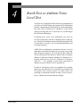
CHAPTER
4
Booth Test or Ambient Noise
Level Test
You have now configured AUDit software in preparation for
your first test. In this chapter, the system will be calibrated to
perform a measurement of ambient levels in the audiometric
test room. This is referred to as a Booth test in the AUDit
software. In doing this test, we will also cover connecting to
the SLM and calibrating it.
If ambient noise levels in an audiometric test room are
excessively high, they can have a masking effect on the subject, effectively raising the measured hearing threshold. This
is most likely to occur if very low hearing threshold levels
are being measured.
AUDit allows simultaneous assessment of noise levels for
audiometric measurements with ears covered or not covered,
in the frequency ranges of 125, 250 and 500 Hz to 8000 Hz.
This test and its pass/fail limits are based on the recommendations of American National Standard on Maximum Permissible Ambient Noise Levels for Audiometric Test Rooms,
ANSI S3.1 - 1991 (R2008). It also allows assessment of
ambient levels per OSHA 1915.95 Appendix D.
In order to consider the worst case conditions for an audiometric test, the ambient noise test should be performed with
all possible noise sources present. If certain sources are
operating at certain times but not at others, it may be necessary to schedule the measurement accordingly.
AUDit Manual
4-1
Assembling the system
The Larson Davis System 824 precision sound level meter
meets all the requirements of the aforementioned standards
and rules for the measurement of ambient noise level in the
audiometric test room. Its low self-noise and internal fractional octave band measurement capability enable it to accurately measure octave and third octave levels much below
the minimum required levels, when using a high sensitivity
microphone such as the Larson Davis model 2575.
Equipment for Booth Test
The equipment listed below is suggested for ambient noise
testing using AUDit.
NOTE:
The
microphone/preamp
assembly may be suspended or supported
with a suitable microphone clamp. If the
dimensions or construction of the audiometric test room require a longer length
of cable or the use of patch panels, care
must be taken not to introduce ground
loops or other problems which can lead
to higher system self-noise levels.
4-2
•
PC with serial port with AUDit
•
CBL006 serial cable
•
System 824 precision sound level meter
•
EXA010 extension cable (optional)
•
PRM902 preamplifier
•
2575 microphone
•
ADP008 1/2 inch preamp to 1 inch microphone thread
adaptor
•
CAL250 precision Sound Pressure Level calibrator
Booth Test or Ambient Noise Level Test
AUDit Manual
Assembling the system
Step 1
Connect the CBL006 from the SERIAL connector
on the butt plate of the 824 SLM to an active serial
port on the computer.
FIGURE 4-1 Connecting CBL006 to 824
AUDit Manual
Assembling the system
4-3
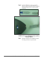
Step 2
Install the PRM902 microphone preamplifier
directly on the SLM or use the EXA010 extension
cable by matching red dots on opposite gender
connectors
FIGURE 4-2 Connecting EXA010 extension cable to
824 and PRM902
Step 3
4-4
Thread the ADP008 onto the PRM902 preamplifier, being careful not to strip the threads
Booth Test or Ambient Noise Level Test
AUDit Manual
Step 4
Thread the 2575 or other microphone onto the
PRM902 preamplifier, being careful not to strip
the threads
FIGURE 4-3 Connecting PRM902, ADP008 and 2575
Microphone
Connecting the SLM
If AUDit is not active, run the software by clicking on the
desktop icon or PCB Piezotronics AUDit (if AUDit was
installed in the default folder). Verify communications port
options in the Test, Preferences..., RS232 Port tab. The System 824, and Audit must be configured with the same baud
rate.
NOTE: The Communications settings
on the System824 are accessed by pressing
, scrolling to Communications, and pressing the
key. Please
refer to the 824 reference manual
(I824.01) for complete instructions.
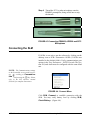
FIGURE 4-4 Connect Menu
Click SLM, Connect to establish connection with the
SLM. You may verify battery level by clicking SLM,
Check Battery... (Figure 4-4).
AUDit Manual
Connecting the SLM
4-5
FIGURE 4-5 Battery Check Window
In this case the battery voltage is 12.2 Volts (Figure 4-5),
with external power. Internal battery status is reported in
percent. Measurements should not be attempted with internal battery readings lower than 10%.
System Acoustic Calibration
NOTE: Calibrator and microphone
must be selectecd as shown in the next
section before calibration check or
change
4-6
The reference level of the sound level meter is calibrated
using a CAL250 or other precision calibrator. This instrument generates a known sound pressure level (SPL) relative
to 20 µPa To calibrate, click SLM, Calibration.
Booth Test or Ambient Noise Level Test
AUDit Manual
FIGURE 4-6 SLM Calibration Window
Hint: Do not hold or bump the calibrator during calibration. Vibrations
may affect readings. All measurement system components should
have reached a stable temperature
before calibrating. Your calibrator
should remain on for the duration of
the calibration (about 30 seconds). If
its battery is low, replace it to extend
the tone duration.
AUDit Manual
AUDit will display the SLM Calibration dialog box. Select
your calibrator and microphone in the pull down menus.
Note that the current level and the difference between it and
the calibrator output level are displayed at the top of the
box.(Figure 4-6) You may use this display to check calibration without changing it, then click on Close to exit. To
change calibration click Set Calibration.
System Acoustic Calibration
4-7
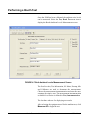
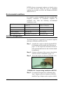
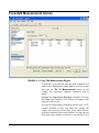
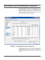
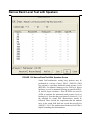
Performing a Booth Test
Once the SLM has been calibrated, the ambient noise levels
can be measured. Select the Test, Booth Test menu item to
display the Booth Ambient Levels Measurement screen.
FIGURE 4-7 Both Ambient Levels Measurement Screen
The first five tabs; Test Information, SL Meter, Preamp, Mic
and Calibrator are used to document the measurement.
Choose the measurement instrumentation and enter the measurement descriptive text. The measurement instrumentation
available for selection is defined in Test, Instrumentation.
The last three tabs are for displaying test results.
After selecting the equipment used for the ambient test, click
Measure All to begin the test.
4-8
Booth Test or Ambient Noise Level Test
AUDit Manual
NOTE: A message (Figure 4-10) will
be displayed while the measurement is
performed.
FIGURE 4-8 Ambient Level Test Message Window
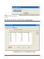
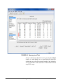
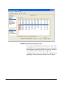
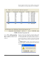
125 - 8K Hz, 250 - 8K Hz, and 500 - 8K Hz and OSHA Tabs
FIGURE 4-9 Ambient Level 125-8kHz Results Window
AUDit Manual
Performing a Booth Test
4-9
NOTE: The limits used in these tabs
are from Tables III and B2 of the American National Standard on Maximum Permissible Ambient Noise Levels for
Audiometric. The OSHA limits are from
OSHA 1910.95 Appendix D
Once the measurement is completed, these three tabs show
Booth Test results.(Figure 4-11) Failed frequencies are indicated with a red mark. In this case, the failed 125 Hz third
octave measured SPL was 26.9 dB SPL, whereas the standard allows (at most) 30.0 for covered, and 24.0 for not covered ears. The exceeded limit values are displayed between
parentheses.
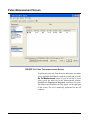
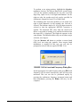
Saving a Booth Test
Once the test is complete, you may save it by clicking OK at
the bottom of the Booth Ambient Levels Measurement
screen, which will display the dialog box shown in (Figure
4-12.
FIGURE 4-10 Ambient Level Test Save Window
4-10
Booth Test or Ambient Noise Level Test
AUDit Manual
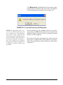
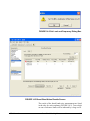
Suspecting Instrument Noise?
Should the readings of the ambient test be questionable, you
may want to check the measurement system noise. There are
a few ways to do this. One simple alternative is to repeat the
measurement with the non-activated calibrator left on top of
the microphone. Another is to do the booth test without a
bias voltage on the microphone. This has the effect of reducing its sensitivity and will show the electrical noise of the
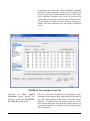
system. The results of this first method are shown in . FIGURE 4-11. The failed 125 Hz third octave measured SPL
was 25.9 dB SPL.
FIGURE 4-11 Booth Ambient Levels Window
As you can see, the noise level at the third octave centered at
125 Hz is 4.4 dB SPL, well below the failing ambient level.
AUDit Manual
Suspecting Instrument Noise?
4-11
This would indicate that the noise was not produced in the
instrumentation.
Hint: To remove the bias voltage
from the microphone, stop the 824
and press
(Setup),
(Right
Arrow) to modify the Audtest.AUD
settings. Scroll to SLM, press
(Right Arrow) and scroll down to
modify SLM parameter Transducer.
Press the
(Check key) and perform an Overall Reset to select Elctret. Remember to rest the transducer
to condnser before making new measurements.
4-12
This measurement has demonstrated the ease of use of the
Larson Davis audiometer calibration system. In the remainder of this manual, a full audiometer calibration will be performed.
Booth Test or Ambient Noise Level Test
AUDit Manual
CHAPTER
5
Audiometer Test System
Assembly
The setup defined for each transducer earlier in the AUDit software
as described in the Audiometer Test
Setup chapter. This will ensure the
proper microphone corrections,
RETS PL's etc. are applied to the
measurement.
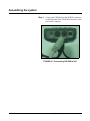
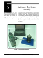
This chapter covers test configurations for the audiometer
transducers which can be calibrated by the LD audiometer
calibration systems. The recommended configurations for
various earphones will be described first. Common elements
such as the PC to System 824 SLM and PRM902
preamplifier connections, inspection and calibration
procedures are explained next. Please contact Larson Davis
if you have any system assembly questions not covered in
this manual.
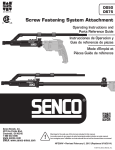
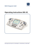
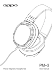
FIGURE 5-1 Audiometer Test System
AUDit Manual
Audiometer Test System Assembly
5-1
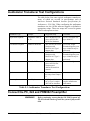
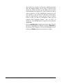
Audiometer Transducer Test Configurations
The table below lists some typical audiometer transducers,
many of which are covered in specifications such as
American National Standards Institute Specifications for
Audiometers, S3.6-2004. When configuring the audiometer
transducer test, the AUDit software suggests or defaults to
appropriate setups. These test setups are covered in greater
detail in subsequent sections.
Transducer Type
Example
Suggested Setup
Comments
Supra-aural earphone
Telephonics TDH-39,
49, 50
AEC100 NBS 9-A coupler or AEC201 IEC
60318 Ear Simulator
Use 4-5 N weight. Test
up to 8000 Hz.
Circumaural earphone
Sennheiser HDA200
AEC201 IEC 60318 Ear
Simulator with
MAEC101.06 Type 1
adaptor plate
Use 9-10N weight.
Extended frequency tests
up to 16000 Hz may be
performed.
Circumaural earphone
Koss HV/1A
AEC201 IEC 60318 Ear
Simulator with
MAEC101.07 Type 2
adaptor plate
Use 9-10N weight.
Extended frequency tests
up to 16000 Hz may be
performed.
Bone vibrator
Radio Ear B-71
AEC100 NBS 9-A coupler or AEC201 Ear
Simulator and
AMC493B Artificial
mastoid
Use 9-10N weight
Speakers
Speakers
Use ambient noise level
test setup from Chapter
4.
Insert earphone
Insert Earphone
AEC202 or AEC203 2.0
cm3 or Type 2 coupler
AEC204 ear simulator
Refer to earphone and
coupler manufacturer
information.
Table 5-1: Audiometer Transducer Test Configurations
Connect the PC, 824 and PRM902 Preamplifier
WARNING!
5-2
Before continuing, ensure that the 824 SLM is turned off.
The 824 should remain off until the system is fully assembled.
Audiometer Test System Assembly
AUDit Manual
Step 1
Connect the CBL006 RS-232 cable from the
SERIAL connector on the butt plate of the 824 to
an active RS-232 port on the computer (FIGURE
5-2).
FIGURE 5-2 Connecting CBL006 to 824
Step 2
Connect the male end of the EXA010 extension
cable to the nose cone of the 824 by matching the
red dots on mating connectors (FIGURE 5-3).
FIGURE 5-3 EXA010 extension cable approaching
System 824
Step 3
AUDit Manual
After the PRM902 microphone preamplifier has
been inserted and treated in the appropriate coupler, (see below) connect it to the nose cone of the
Connect the PC, 824 and PRM902 Preamplifier
5-3
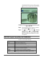
824 with the EXA010 extension cable by matching the red dots on mating connectors (FIGURE 54).
FIGURE 5-4 Preamp connecting to extension cable
and to AEC100
Step 4
The 824 SLM may now be turned on by parameters. Pressing the
key on the 824.
Step 5
Press
, scroll down with the
to Communication and press
to edit Serial Comm.
parameters. Set the parameters as desired. 9600
Baud, serial address 000 and Hdwr flow control
are suggested.
AEC100 Coupler Assembly and Calibration
For this you will need the following:
Part Number
Description
AUDit
AUDit software running on a PC
CBL006 serial cable
Serial cable 8 pin mini DIN to DB-9
824
System824 precision sound level meter (SLM)
EXA010
10 foot extension cable with 7 pin LEMO connectors
2575
1" precision air condenser microphone
PRM902
1/2" diameter low noise microphone preamplifier
CAL250
Precision SPL calibrator with 114 dB SPL output at 250 Hz
The following are AEC100 components:
5-4
Audiometer Test System Assembly
AUDit Manual
Part Number
Description
MAE100.1
6 cc coupler
MAE100.3
1 inch coupler cap
SP-MAE100.40
Artificial ear base
MAE100.6
Earphone retainer ring
MAEC100.7
Mass handle screws into SAEC100.01
SAEC100.01
Weight assembly and rubber no handle
ACC001
Vibration isolation pad
AEC100 Initial Assembly
WARNING!
Before continuing, ensure that the 824 SLM is turned off.
The 824 should remain off until the system is fully assembled.
The AEC100 artificial ear is an elegant, compact precision
coupler built to provide a lifetime of dependable use with
reasonable care. Read the following instructions to unpack,
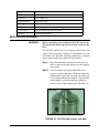
inspect and assemble the coupler for the first time.
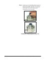
Step 1
Place the cushioned vibration isolation pad on a
table or other such stable surface near the audiometer system.
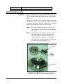
Step 2
Visually inspect the coupler (MAE100.1) for
gouges, scratches and dents which may affect the
measurement, especially around the lip which will
be in contact with the test earphone. Verify that the
small metallic wire in the capillary leak hole is
present with no other obstructions (FIGURE 5-5).
Leak Hole
FIGURE 5-5 AEC100 with coupler, leak hole
AUDit Manual
AEC100 Coupler Assembly and Calibration
5-5
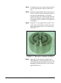
Step 3
If installed, remove the coupler cap (MAE100.3)
from the artificial ear base (SP-MAE100.40) by
gently unscrewing it counterclockwise (FIGURE
5-6).
FIGURE 5-6 Protective ring being removed from
AEC100
When removing the preamplifier,
unscrew it by holding on its body, not
the connector sleeve.
5-6
Step 4
Inspect a spring-loaded contact at the center of the
base visually. It should extend approximately 5
mm above the threaded ridge. The insulator
around it should be free of dust and other particles.
Please do not handle the contact and protect it by
keeping the coupler cap on whenever a microphone is not installed.
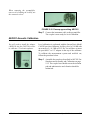
Step 5
Install the 1" microphone (LD Model 2575 or
equivalent) on the center of the artificial ear base.
The microphone should install easily: screw it finger tight (FIGURE 5-7).
FIGURE 5-7 2575 Microphone and AEC100
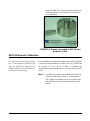
Step 6
Insert the 1/2" microphone preamplifier (LD
Model PRM902 or equivalent) gently in the side
port until its threads contact those of the base. The
preamplifier should install easily: screw it finger
Audiometer Test System Assembly
AUDit Manual
tight (FIGURE 5-8). Connect the instrument cable
to the preamplifier. The coupler is now ready for
level calibration.
FIGURE 5-8 Preamp connecting to AEC100 and
Extension Cable
AEC100 Acoustic Calibration
It is necessary to remove the calibrator 1/2 inch adaptor (ADP019) ring
from the CAL250 to allow the one
inch microphone to fit inside the calibrator one inch opening.
Level calibration is performed with the Larson Davis Model
CAL250 precision calibrator. It offers a level of 114 dB with
an accuracy of +/-0.2 dB at 251.2Hz. To calibrate the
measurement system and artificial ear, follow the procedure
below.
Step 1
AUDit Manual
Assemble the coupler as described in the AEC100
Acoustic Calibration on page 5-7 section above.
The coupler base should rest on the isolation pad
and ambient noise and vibration should be minimized.
AEC100 Coupler Assembly and Calibration
5-7
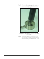
Step 2
Place the calibrator opening on the microphone
and seat it fully (FIGURE 5-9). Note: Do not
remove the microphone grid cap.
FIGURE 5-9 CAL250 being lowered onto 2575
microphone
Step 3
5-8
Activate the calibrator as prompted by the software and verify the stability of the indication on
the measurement system (FIGURE 5-10). Do not
Audiometer Test System Assembly
AUDit Manual
hold the calibrator during calibration. Its tone will
last about one minute (depending on the battery)
and will turn off automatically.
FIGURE 5-10 Starting Calibration tone with on
switch
In actual practice, for most testing,
the grid cap does not need to be
removed. This will help reduce the
possibility of accidental damage to
the delicate and expensive precision
microphone diaphragm.
AUDit Manual
Step 4
AUDit requires a calibration in each of two measurement ranges. The calibrator tone may have to
be reactivated for the second calibration as
prompted by the software.
Step 5
See Note at left before proceeding. After the calibration, carefully remove the grid cap by holding
the microphone body and unscrewing the grid
counterclockwise (FIGURE 5-11). Store it in the
microphone case.
AEC100 Coupler Assembly and Calibration
5-9
FIGURE 5-11 Removing grid cap from 2575
Microphone
Step 6
Replace the grid cap with the protective coupler
cap (MAE100.3), being careful not to impact the
delicate diaphragm (FIGURE 5-12).
FIGURE 5-12 Installing Protective Ring on 2575
Microphone
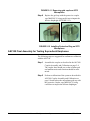
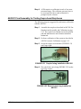
AEC100 Final Assembly for Testing Supra-Aural Earphones
The following steps are suggested for audiometer calibration
with the AEC100.
5-10
Step 1
Assemble the coupler as described in the AEC100
Coupler Assembly and Calibration on page 5-4.
The coupler base should rest on the isolation pad
and ambient noise and vibration should be minimized.
Step 2
Perform a calibration of the system as described in
AEC100 Coupler Assembly and Calibration on
page 5-4 and replace the microphone grid cap with
the protective coupler cap (MAE100.3), being
careful not to impact the delicate diaphragm.
Audiometer Test System Assembly
AUDit Manual
.
FIGURE 5-13 Coupler being installed on AEC100
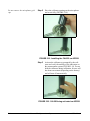
Step 3
Center the test earphone on the coupler. Lower the
black retainer ring over the earphone, holding the
earphone cable in line with the notch (FIGURE 514).
FIGURE 5-14 Retainer Ring being installed over
headphone.
AUDit Manual
AEC100 Coupler Assembly and Calibration
5-11
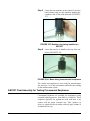
Step 4
Lower the mass by its handle to the top of the earphone (FIGURE 5-15).
FIGURE 5-15 Mass being installed on AEC100.
The coupler and earphone are now ready for measurement.
AEC201 Ear Simulator and Assembly and Calibration
For this you will need:
Part Number
Description
AUDit
AUDit software running on a PC
CBL006
Serial cable 8 pin mini DIN to DB-9
824
System824 precision sound level meter (SLM)
EXA010
10 foot extension cable with 7 pin LEMO connectors
377A13
1/2" precision air condenser random incidence microphone
PRM902
1/2" diameter low noise microphone preamplifier
CAL250 or CAL200
Precision SPL calibrator with 114 dB SPL output at 250 Hz with
1" to 1/2" calibrator opening adaptor (ADP019)
The following are AEC201 components:
Artificial ear base including base, contacts, insulator and pad
AEC201.F
5-12
Coupler
AEC100.06
Type 1 adaptor (optional)
AEC201-2
Type 2 adaptor
MAEC100.08
Conical ring
MAE100.6
Earphone retainer ring
MAEC100.7
Mass handle screws into SAEC100.1
SAEC100.01
Weight assembly and rubber - no handle
ACC001
Vibration isolation pad
Audiometer Test System Assembly
AUDit Manual
Part Number
Description
AMEC101.10
Bag Weight 9.5 Newton (946g)
AEC201 Initial Assembly
WARNING!
Before continuing, ensure that the 824 SLM is turned off.
The 824 should remain off until the system is fully assembled.
The AEC201 artificial ear is a versatile coupler and allows
measurement of a variety of earphones with its provided
accessories. Read the following instructions to unpack,
inspect and assemble the coupler for the first time.
Step 1
Place the cushioned vibration isolation pad on a
table or other such stable surface near the audiometer system.
Step 2
Visually inspect the coupler for gouges, scratches
and dents which may affect the measurement,
especially around the sharp lip which will be in
contact with the test earphone. Verify that the
small tube in the capillary leak hole is present with
no other obstructions (FIGURE 5-16).
Coupler
Spring
Loaded
contact
Leak Hole
FIGURE 5-16 AEC201 with coupler, leak hole
AUDit Manual
AEC201 Ear Simulator and Assembly and Calibration
5-13
Step 3
If installed, remove the coupler from the artificial
ear base by gently unscrewing it counterclockwise.
Step 4
Inspect the spring-loaded contact at the center of
the base visually. It should extend approximately 5
mm above the threaded ridge. The insulator
around it should be free of dust and other particles.
Please do not handle the contact and protect it by
keeping the coupler on whenever a microphone is
not installed.
Step 5
Install the 1/2" microphone PCB model 377A13
on the center of the artificial ear base. The microphone should install easily: screw it finger tight
(FIGURE 5-17)
.
FIGURE 5-17 Microphone installed on AEC201
Step 6
5-14
Insert the 1/2" microphone preamplifier (LD
Model PRM902 or equivalent) gently in the side
port until its threads contact those of the base. The
preamplifier should install easily: screw it finger
tight (FIGURE 5-18).
Audiometer Test System Assembly
AUDit Manual
When removing the preamplifier,
unscrew it by holding on its body, not
the connector sleeve
FIGURE 5-18 Preamp approaching AEC201
Step 7
Connect the instrument cable to the preamplifier.
The coupler is now ready for level calibration.
AEC201 Acoustic Calibration
You will need to install the adapter
(ADP019) into the CAL250 in order
to calibrate 1/2 inch microphones.
ADP019
AUDit Manual
Level calibration is performed with the Larson Davis Model
CAL250 precision calibrator. It offers a level of 114 dB with
an accuracy of +/-0.2 dB at 251.2 Hz. You will have to insert
the provided 1" to 1/2" adaptor in the top of the calibrator.
To calibrate the measurement system and artificial ear,
follow the procedure below.
Step 1
Assemble the coupler as described in AEC201 Ear
Simulator and Assembly and Calibration on page
5-12. The coupler base should rest on the isolation
pad and ambient noise and vibration should be
minimized.
AEC201 Ear Simulator and Assembly and Calibration
5-15
Do not remove the microphone grid
cap.
Step 2
Place the calibrator opening on the microphone
and seat it fully (FIGURE 5-18).
FIGURE 5-19 Installing the CAL250 on AEC201
Step 3
Activate the calibrator as prompted by the software and verify the stability of the indication on
the measurement system (FIGURE 5-19). Do not
hold the calibrator during calibration. Its tone will
last about one minute (depending on the battery)
and will turn off automatically.
FIGURE 5-20 CAL250 being activated on AEC201
5-16
Audiometer Test System Assembly
AUDit Manual
Step 4
AUDit requires a calibration in each of two measurement ranges. The calibrator tone may have to
be reactivated for the second calibration as
prompted by the software.
AEC201 Final Assembly for Testing Supra-Aural Earphones
The following steps are suggested for audiometer calibration
with the AEC201.
Step 1
Assemble the coupler as described in AEC201 Ear
Simulator and Assembly and Calibration on page
5-12. The coupler base should rest on the isolation
pad and ambient noise and vibration should be
minimized.
Step 2
Perform a calibration of the system as described in
AEC201 Acoustic Calibration on page 5-15.
Step 3
Screw the coupler over the base (FIGURE 5-21)
until finger tight.
FIGURE 5-21 Coupler being installed on AEC201
Step 4
Place the black conical ring (FIGURE 5-22) on the
top of the coupler.
Black Ring installed
FIGURE 5-22 Black Conical ring installed on
AEC201
AUDit Manual
AEC201 Ear Simulator and Assembly and Calibration
5-17
Step 5
Center the test earphone on the coupler. Lower the
black retainer ring over the earphone, holding the
earphone cable in line with the notch (FIGURE 523).
FIGURE 5-23 Retainer ring being installed on
AEC201
Step 6
Lower the mass by its handle to the top of the earphone (FIGURE 5-24).
FIGURE 5-24 Mass being lowered onto headphone
The coupler and earphone are now ready for measurement.
Set tone type, level and presentation and make the reading
on the measurement system.
AEC201 Final Assembly for Testing Circumaural Earphones
Circumaural earphones are available for audiometers using
extended high-frequencies, from 8000 to 16000 Hz. These
earphones typically rest against the head with little or no
contact with the pinna (external ear). Their speaker (or
driver) is coupled to the ear with a relatively large volume of
air under the ear cap.
5-18
Audiometer Test System Assembly
AUDit Manual
RETSPLs for two circumaural earphones are listed in Annex
C of ANSI S3.6-2010. These two types of cirumaural
earphones are available in AUDit: the Sennheiser HDA200
and Koss HV/1A.
Environmental conditions
It is stated in various standards that the extended highfrequency calibration of circumaural earphones be
performed only when the following environmental
conditions are met.
Condition
Range in ANSI S3.6-2010
(Annex C)
Range in IEC 60318-1:2009
Clause 6 Calibration
Ambient Pressure
98 to 104 kPa
98.325 to 104.325 kPa
Temperature
18 to 26 degrees C
20 to 26 degrees C
Relative Humidity
30 to 80% RH
30 to 70% RH
Any condition not met
Calibration is not allowed
State actual values
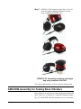
AEC201 Configuration
The following steps are suggested for circumaural earphone
audiometer calibration with the AEC201.
Step 1
Assemble the coupler as described in theAEC201
Ear Simulator and Assembly and Calibration on
page 5-12. The coupler base should rest on the isolation pad and ambient noise and vibration should
be minimized.
Step 2
Perform a calibration of the system as described in
AEC201 Acoustic Calibration on page 5-15.
Step 3
Screw the coupler over the base (FIGURE 5-25).
FIGURE 5-25 Coupler being installed on AEC201
Step 4
AUDit Manual
For earphones designed to be calibrated with a
Type 1 adapter such as the Sennheiser HDA200,
install the Type 1 adapter on the coupler, with the
AEC201 Ear Simulator and Assembly and Calibration
5-19
cylindrical rim facing down. Place the black conical ring on the top of the coupler and plate, with its
flat base on the bottom (FIGURE 5-26).
FIGURE 5-26 AEC201 with Type 1 Adapter
installed
Step 5
For earphones designed to be calibrated with a
Type 2 adapter such as the Koss HV/1A, use the
Type 2 adapter, which has crenellated distance
clamps around its circumference. Do not use the
black conical ring (FIGURE 5-27).
FIGURE 5-27 Type 2 adapter installed on AEC201
Step 6
5-20
Center the test earphone on the coupler or place it
as recommended if the cushion is asymmetrical.
Audiometer Test System Assembly
AUDit Manual
Step 7
ANSI S3.6-2010 requires a static force of 9 to 10
N on the earphone during calibration. Use the
large weight bag (FIGURE 5-28).
FIGURE 5-28 Sennheiser earphone and weight
bag being installed on AEC201
The coupler and earphone are now ready for measurement.
AMC493B Assembly for Testing Bone Vibrators
Bone vibrators are used to test sound conduction through the
head. Their use is limited to a restricted frequency range.
The LD AMC493B artificial mastoid uses an innovative
AUDit Manual
AMC493B Assembly for Testing Bone Vibrators
5-21
design to allow bone vibrator calibration using an AEC100
or AEC201. The AMC493B converts the force applied by
the bone vibrator to an acoustic signal which can then be
measured acoustically by the calibration system. The
following steps are suggested for bone vibrator transducer
calibration.
In addition to the components of the AEC100 or AEC201,
you will need the following equipment:
Part Number
Description
AMC493B
Artificial mastoid
MAE100.55
Additional ring mass
Environmental conditions
Bone vibrator calibration measurements are extremely
sensitive to temperature and humidity. One important
advantage of the AMC493B is its very low thermal mass,
which allows it to stabilize to the temperature of the test area
very quickly, typically within a few tens of minutes. The
sensitivity and mechanical impedance data supplied for the
AMC493B were measured at 23 °C and 50% RH.
The basis for ANSI Standard S3.131987 (Reaffirmed 1993) Mechanical
Coupler for Measurement of Bone
Vibrators is IEC 60373:1990-01 of
the same name. This standard states
that in general, temperature corrections can not be used directly to correct data not taken at the reference
temperature of 23 degrees C, as the
effect of temperature on the bone
vibrator is unknown. See also
IEC60318-6:2007 5.5
Although AUDit performs a temperature correction, it is
recommended to make measurements as close as possible to
the temperature at which the AMC493B mastoid was
calibrated.
Except during use, the AMC493B is kept in a case with
temperature and humidity meter. Place these temperature
and humidity number corrections in the AUDit software,
along with the local pressure, to enhance the mastoid
accuracy.
Test Configuration
5-22
Step 1
Assemble the AEC100 or AEC201. The coupler
base should rest on the isolation pad and ambient
noise and vibration should be minimized.
Step 2
Perform a calibration of the system as described
in.
Step 3
Place the coupler over the base (FIGURE 5-13).
Audiometer Test System Assembly
AUDit Manual
Step 4
Lightly place the AMC493B artificial mastoid on
the top of the coupler (FIGURE 5-29) with ringshaped polymer.There must not be any metal to
metal contact. Press down slightly on the
AMC493B to secure its position.
FIGURE 5-29 Mastoid placed on AEC100
AUDit Manual
AMC493B Assembly for Testing Bone Vibrators
5-23
Step 5
Center the test vibrator contact surface on the circular resilient surface of the AMC493B. Ensure
that there is no contact between the vibrator body
and the AMC493B metallic rim (FIGURE 5-30).
FIGURE 5-30 Vibrator being placed and
centered on mastoid
5-24
Audiometer Test System Assembly
AUDit Manual
Step 6
Assemble the additional mass ring over the handle
of the AEC100 mass (FIGURE 5-31)
FIGURE 5-31 Additional mass being placed on
AEC100 weight
When removing the AMC493B artificial mastoid from the coupler, gently
twist it off to break the seal. For
more information, refer to the
AMC493B manual.
Step 7
Lower the black retainer ring over the vibrator,
holding the vibrator cable in line with the notch
(FIGURE 5-32).
FIGURE 5-32 Retainer Ring being placed over
vibrator
AUDit Manual
AMC493B Assembly for Testing Bone Vibrators
5-25
Step 8
Lower the mass on top of the vibrator by its handle
(FIGURE 5-33).
FIGURE 5-33 Artificial ear with vibrator and
mass installed
The coupler and vibrator are now ready for measurement.
Set tone type, level and presentation and make the reading
on the measurement system.
B&K 4930 Assembly for Testing Bone Vibrators
Unlike the LD AMC493B, the Brüel & Kjær artificial
mastoid uses an accelerometer to measure the bone vibrator
output. The LD audiometer calibration system can interface
with the B&K mastoid by using the high input impedance
PRM902 preamplifier and a suitable adapter.
If the cable from the B&K 4930 has a 10-32 microdot
connector (small threaded coaxial connector), use the
optional ADP007. On the other hand, if your artificial
mastoid has a BNC coaxial connector, use the ADP006
provided with the LD system. You will also need the
following:
5-26
Part Number
Description
AUDit
AUDit software running on a PC
CBL006
Serial cable 8 pin mini DIN to DB-9
Audiometer Test System Assembly
AUDit Manual
Part Number
Description
824
System824 precision sound level meter (SLM)
PRM902
1/2" diameter low noise microphone preamplifier
ADP008
1" microphone to 1/2" preamp adapter
2575
1" precision air condenser microphone
CAL250
Precision SPL calibrator with 114 dB SPL output at 250 Hz
B&K 4930
Artificial Mastoid and accessories
ADP007 or
ADP006
Microdot to 1/2" preamp adapter for charge-coupled accelerometer or BNC to 1/2" microphone thread adapter, 47 if with shorting
cap
Larson Davis recommends making measurements as close
as possible to the temperature at which the artificial mastoid
was calibrated.
Test Configuration
Step 1
Assemble the measurement system as in the section on: Connecting the PC, 824 and PRM902 Preamplifier.
Step 2
Thread the ADP008 onto the preamplifier and
then thread the 2575 microphone on the preamplifier (FIGURE 5-34).
FIGURE 5-34 ADP008 being installed on PRM902
Step 3
AUDit Manual
Perform a system SPL calibration using the
CAL250.
AMC493B Assembly for Testing Bone Vibrators
5-27
Step 4
Remove the ADP008 adaptor and 2575 microphone, and replace them with the appropriate
adaptor to connect to the artificial mastoid (FIGURE 5-35).
ADP007
ADP006
FIGURE 5-35 Adapters to connect to B & K
mastoid
Step 5
Install the bone vibrator on the B&K 4930 as
described in the B&K user manual.
The coupler and vibrator are now ready for measurement.
5-28
Audiometer Test System Assembly
AUDit Manual
CHAPTER
6
Hearing Level Test
Once AUDit has been configured with the test
instrumentation and audiometer information, an actual
audiometer calibration may be performed. The main
measurement screen is accessed from the Audiometer Test
Setup screen by pressing the OK button.
Calibration Main Measurement Screen
FIGURE 6-1 Main Measurement Screen
The main measurement screen allows one to enter the test
date and technician name. The tested audiometer
manufacturer, model and serial number are displayed as
AUDit Manual
Hearing Level Test
6-1
entered in the previous setup. A table of tests and
transducers shows the available tests for the particular
audiometer. For example, the Hearing Level test may be
performed with supra-aural, insert or circumaural earphones,
as well as with the bone vibrator and speakers. Appropriate
corrections are applied within each test using microphone,
coupler and standard adjustments.
The SLM should be calibrated before
a measurement is performed.
6-2
To begin the audiometer calibration process, highlight the
Hearing Level test with the pointer and press the Go To
Measurement button. If you are already in a test screen,
press the same test in the Measurements window at the
upper left.
Hearing Level Test
AUDit Manual
Hearing Level Test with Earphone Transducers
FIGURE 6-2 Hearing Level Screen
The Hearing Level screen is typical of the measurement
screens. On the left, below the measurement table, you will
find the list of transducers for which the audiometer hearing
level may be tested. The large box at the right has multiple
tabs and varies according to the transducer being tested. For
example, all earphones types have four tabs: Low and High
Freq. Input levels, Left and Right. On the other hand, the
bone vibrator has only two tabs: Input levels and Bone
Vibrator Levels. In this section, the supra-aural earphone
transducers will be calibrated. The procedure is the same for
insert and circumaural earphones.
AUDit Manual
Hearing Level Test with Earphone Transducers
6-3
To perform a test of the supra-aural earphones, highlight the
Supra-aural Earphone transducer list item. The four Supraaural Earphone Hearing Level tabs will appear on the right
part of the screen. Default low and high frequency input
levels are typically set to 70 dB HL on each tab. Each value
may be changed by highlighting it and entering a new value.
Use the pointer or the TAB key to move to another
frequency.
Once the input levels have been verified, one may select
which earphone to test by pressing on the Left or Right tab.
FIGURE 6-3 Active Frequencies List
The list of the active frequencies selected earlier in the
audiometer setup appears in the right window. Note the
headers at the top of the table. The measured SPL value
6-4
Hearing Level Test
AUDit Manual
from the sound level meter is converted to hearing level, and
the deviation from the target SPL is displayed.
The row of buttons at the bottom of the screen allows the
technician to:
•
Adjust - adjust the audiometer in real-time if a
precision output level adjustment is available
•
Measure All - measure all frequencies sequentially
with software prompts
•
Measure Selected - measure only the currently
highlighted frequency with software prompts
•
Next Test - move to the next measurement in the
Measurements list in the upper left window
Press Measure All to perform a hearing level test on the
left earphone. AUDit then displays the prompt shown in
Figure 6-4 for the first frequency:
FIGURE 6-4 Prompt for First Frequency Setting
Set the appropriate level and frequency on the audiometer
then press OK. Each frequency will be tested until all have
been measured. This can be done in less than one minute by
pressing the audiometer frequency increment button and
then immediately pressing the Enter (OK) key on the
computer. In the example, all frequencies passed except for
the last 8000 Hz. This is indicated by a large red X next to
the frequency.
AUDit Manual
Hearing Level Test with Earphone Transducers
6-5
FIGURE 6-5 Hearing Level Test
It may be desired to adjust this level by pressing the Adjust
button. A small dialog box is then displayed where the
technician may select the current frequency and adjust the
level potentiometer of the audiometer to fall within the listed
target SPL range.
6-6
Hearing Level Test
AUDit Manual
FIGURE 6-6 Adjust Level Dialog Box
Once this is done, the failed frequency may be retested with
the Measure Selected button.
Hearing Level Test with Bone Vibrator
FIGURE 6-7 Hearing Level Test with Bone Vibrator Screen
AUDit Manual
Hearing Level Test with Bone Vibrator
6-7
To perform a test of the bone vibrator transducer, highlight
the Bone Vibrator transducer list item. The Hearing Level
screen for the bone vibrator transducer has two tabs: Input
Levels and Bone Vibrator Levels. In the first tab, the test
bone vibrator levels can be specified or set to default values.
Use the pointer or TAB key to move from one frequency to
another. The Bone Vibrator Levels tab displays calibration
results.
FIGURE 6-8 Bone Vibrator Levels Tab
Checking the Show Applied
Corrections option displays the
following columns: In Lvl, RETFL,
FL, Mast, Mic, T, H, and P.
6-8
The list of the active frequencies selected earlier in the
audiometer setup appears in the right window. Placement of
the bone vibrator affects output. Select the proper option:
Mastoid or Forehead. Note the headers at the top of the
table. The measured SPL value from the sound level meter is
converted to hearing level, and the deviation from the target
SPL is displayed.
Hearing Level Test
AUDit Manual
Not all frequencies have a valid
RETSPL, i.e., 160 Hz.
The row of buttons at the bottom of the screen allows the
technician to:
•
Adjust - adjust the audiometer in real-time if a
precision output level adjustment is available
•
Measure All - measure all frequencies sequentially
with software prompts
•
Measure Selected - measure only the currently
highlighted frequency with software prompts
•
Next Test - move to the next measurement in the
Measurements list in the upper left window
•
OK - end the current test
•
Cancel - cancel the current test
Press Measure All to perform a hearing level test on the
bone vibrator. If you are using a Larson Davis mastoid, you
will be prompted to enter temperature and humidity values
(Figure 6-9) used within the software for artificial mastoid
corrections.
FIGURE 6-9 Temperature/Humidity Entry Screen
Enter the humidity value, as well as the temperature in
degrees centigrade as indicated on the meter inside the
AMC493B storage case.
AUDit then displays the prompt shown in Figure 6-9 for the
first frequency:
AUDit Manual
Hearing Level Test with Bone Vibrator
6-9
FIGURE 6-10 Hearing Level Set Screen
Set the appropriate level and frequency then press OK. Each
frequency will be tested until all have been measured
consecutively. This can be done in less than one minute by
pressing the audiometer frequency increment button and
then immediately pressing the Enter (OK) key on the
computer.
6-10
Hearing Level Test
AUDit Manual
Hearing Level Test with Speakers
FIGURE 6-11 Hearing Level Test with Speakers Screen
Sound field audiometric testing using speakers may be
performed in a variety of ways. Table 9 of ANSI S3.6-2004
lists reference equivalent threshold sound pressure levels
(RETSPL) for binaural listening in free field at 0 degree
incidence, as well as monaural listening for 0, 45 and 90
degree incidence. These RETSPLs are used in AUDit to
translate the measured sound pressure levels to hearing
levels. Note that the prescriptions in section 9.5.1 of the
standard for sound field characteristics should be followed.
These include the requirement that the ambient noise in the
sound field shall not exceed that specified in ANSI S3.11991. The ambient noise Booth test in AUDit is helpful in
making this determination.
To perform a test using speakers, highlight the Speakers
transducer list item. The Hearing Level screen for the
AUDit Manual
Hearing Level Test with Speakers
6-11
speakers transducers has five tabs, as shown previously in
F:FIGURE 6-<n=1>:
•
Left
•
Right
•
Low Freq. Input Levels
•
High Freq. Input Levels
•
Binaural
If the Left tab is selected, as shown, an incidence angle of 0,
45 or 90 degrees must be chosen so that the appropriate
RETSPL correction is applied. Note the headers at the top of
the table. Measured SPL value from the sound level meter is
converted to hearing level, and the deviation from the target
SPL is displayed. The Right tab operates in exactly the same
manner. The Binaural tab has only one incidence angle
selection, zero degrees.
For Low Freq. Input Level or High Freq. Input Level
tabs, the speaker test levels can be specified for audiometric
frequencies from 125 to 20000 Hertz. Use the pointer or
TAB key to move from one frequency to another and enter
the desired test level.
The row of buttons at the bottom of the screen allows the
technician to do the following:
6-12
•
Adjust - adjust the audiometer in real-time if a
precision output level adjustment is available
•
Measure All - measure all frequencies sequentially
with software prompts
•
Measure Selected - measure only the currently
highlighted frequency with software prompts
•
Next Test - move to the next measurement in the
Measurements list in the upper left window
•
OK - end the current test
•
Cancel - cancel the current test
Hearing Level Test
AUDit Manual
Press Measure All to perform a hearing level test using the
speakers. Since frequency modulation is required for this
test, you will also be prompted to select a FM test signal.
FIGURE 6-12 Level and Frequency Set Dialog
Set the appropriate level and frequency then press OK. Each
frequency will be tested until all have been measured
consecutively. This test can be performed in less than one
minute by pressing the audiometer frequency increment
button and then immediately pressing the Enter key (OK) on
the computer.
AUDit Manual
Hearing Level Test with Speakers
6-13
6-14
Hearing Level Test
AUDit Manual
CHAPTER
7
Frequency Test
Once AUDit has been configured with the test
instrumentation and audiometer information, an actual
audiometer calibration may be performed. The main
measurement screen is accessed from the Setup screen by
pressing the OK button.
Calibration Main Measurement Screen
FIGURE 7-1 Main Measurement Screen
The main measurement screen (FIGURE 7-1) allows you to
enter the test date and technician name. The tested
audiometer manufacturer, model and serial number are
AUDit Manual
Frequency Test
7-1
displayed as entered in the previous setup. A table of tests
and transducers shows the available tests for the particular
audiometer. For example, the Frequency test may be
performed with supra-aural, insert or circumaural earphones.
Appropriate corrections are applied within each test using
appropriate microphone, coupler and standard adjustments.
To continue the audiometer calibration process, highlight the
Frequency test with the pointer and press the Go To
Measurement button. If you are already in a test screen,
press the same test in the Measurements window. Note that
the SLM should be calibrated before a measurement is
performed.
Frequency Test with Earphone Transducers
FIGURE 7-2 Frequency Test Screen
7-2
Frequency Test with Earphone Transducers
AUDit Manual
Checking the Show Applied Corrections on this tab displays the %Freq
column, which shows the percentage
difference allowed for the associated
frequency to pass the test.
The Frequency test screen (FIGURE 7-2) is the same for all
earphone types. On the left, below the measurement table,
the transducers list contains supra-aural, insert and
circumaural earphones. All earphones types have two tabs:
Left and Right. In this example, the supra-aural earphone
transducers will be calibrated. The procedure is the same for
insert and circumaural earphones.
To perform a test of the supra-aural earphones, highlight the
Supra-aural Earphone transducer list item. The Supra-aural
Earphone Frequency Accuracy tabs will appear on the right
part of the screen. One may select the test earphone by
pressing on the Left or Right tab.
The list of the active frequencies selected earlier in the
audiometer setup process appears in the right window. Note
the headers at the top of the table. The dial and measured
frequency value from the sound level meter are displayed,
and the deviation from the target frequency is displayed for
each frequency.
The row of buttons at the bottom of the screen allows the
technician to:
•
Measure All - measure all frequencies sequentially with
software prompts
•
Measure Selected - measure only the currently highlighted frequency with software prompts
•
Next Test - move to the next measurement in the Measurements list in the upper left window
•
OK - end the current test
•
Cancel - cancel the current test
Press Measure All to perform a frequency test on the left
earphone. AUDit then displays the prompt shown in
FIGURE 7-3 for the first frequency:
FIGURE 7-3 Set Level and Frequency Dialog Box
AUDit Manual
Frequency Test with Earphone Transducers
7-3
Set the appropriate level and frequency then press OK. Each
frequency will be tested until all have been measured
consecutively. Frequency measurement is performed
accurately by a dedicated counter in the Model 824 sound
level meter. A number of counter values are compared to
ensure an accurate reading. This process may take a few
seconds. In this example, all frequencies higher than 750 Hz
are out of tolerance.(FIGURE 7-4) This is indicated by a
large red X next to each frequency.
FIGURE 7-4 Frequency Test Results Box
7-4
Frequency Test with Earphone Transducers
AUDit Manual
NOTE: If the frequency reading is not
stable, it could be due to noise that is
coupled into the artificial ear. Possible
sources are HVAC, abient noise, (room
noise) or vibration. Make sure to use the
pad and test on a solid surface. Verify
that the ambient noise levels are satisfactorily low.
AUDit Manual
A failed frequency may be retested after adjustment by
highlighting it and pressing the Measure Selected button.
The Adjust button is inactive in this screen because
frequency measurements are slightly longer and the display
is not effective for adjustment in real time.
Follow the same procedure to test the right earphone.
Frequency Test with Earphone Transducers
7-5
7-6
Frequency Test with Earphone Transducers
AUDit Manual
CHAPTER
8
Linearity Test
Various requirements regarding signal level controls appear
in Section 7 of ANSI S3.6-2004.
AUDit allows the measurement of linearity from the
maximum hearing level down to the noise floor of the
measurement system. The test frequency, maximum dBHL
and dial step may be selected by the technician. Defaults are
1000 Hz 110 dBHL maximum level and 5 dBHL steps.
Linearity Measurement Screen
FIGURE 8-1 Linearity Measurement Screen
To perform a linearity test from the main audiometer test
status screen, follow these steps:
AUDit Manual
Linearity Test
8-1
The SLM should be calibrated before
a measurement is performed. In this
example, the supra-aural earphone
transducers will be calibrated. The
procedure is the same for insert and
circumaural earphones.
Step 1
Highlight the Linearity test with the pointer and
click the Go To Measurement button. If you are
already in a test screen, press the same test in the
Measurements window.
Step 2
Highlight the Supra-aural Earphone transducer
list item. The Supra-aural Earphone Linearity tabs
will appear on the right part of the screen. One
may select which earphone to test by clicking on
the Left or Right tab.
Step 3
Select the desired frequency and dial step (10, 5, 2
or 1 dB) from the drop down lists and enter the
appropriate maximum output level of the audiometer.
Step 4
Click the Measure All button to perform a linearity test on the right earphone. AUDit then displays
the prompt shown in Figure 8-2 to measure the
lower end of the test range:
FIGURE 8-2 Level and Frequency Set Dialog Box
Hint: To test only a certain part of
the hearing level control linearity;
First set the upper level in the Max
dBHL entry field. Then present the
lower level on the audiometer during
the noise floor test.
Step 5
Set the audiometer to the prompted level and frequency and then click OK. There may be a delay
while the measurement system gain is adjusted.
Once the noise floor has been measured (e.g. 1.0
dB), it will appear on the Linearity screen (FIGURE 8-1.
All level steps from the maximum level to the noise floor
will be tested consecutively with AUDit prompts to change
the level. Steps which are out of tolerance will be indicated
8-2
Linearity Measurement Screen
AUDit Manual
by a large red X on the results screen, as shown in FIGURE
8-3.
FIGURE 8-3 Noise Floor Test Results Screen
A failed level may be retested after adjustment by
highlighting it and clicking the Measure Selected button.
Step 6
AUDit Manual
Follow the same procedure to test the other earphone.
Linearity Measurement Screen
8-3
8-4
Linearity Measurement Screen
AUDit Manual
CHAPTER
9
Distortion Test
Accurate distortion measurements of the pure tone signal
source are performed by using narrow band fast Fourier
transform (FFT) analysis. Distortion can affect audiometric
evaluations and may indicate hardware problems. The
maximum permissible levels in percent are listed in Table 3
of ANSI S3.6-2010. In general, total harmonics should be
less than 2.5% for air conduction and less than 5.5% for
bone conduction.
Harmonic distortion is measured at the level listed in ANSI
S3.6: Table 4 or the maximum hearing level of the
audiometer, whichever is lower. Limitations in the frequency
response of the measurement system dictate that distortion
measurements above 5000 Hz should be made across the
electrical terminals of the transducer. The ADP010
Audiometer Earphone Testing Adaptor is ideal for this
purpose. Insert it in the connection to the transducer, and
then connect its BNC to the ADP006 BNC to 1/2"
preamplifier adaptor on the PRM902.
Total harmonic distortion is
defined as follows:
Lf2 2
f3 2
THD percent = 100 -------- + L -----
Lf1
f1
where f1 is the fundamental frequency, f2 the first harmonic,
etc. Levels must be expressed in linear units in this formula.
AUDit Manual
Distortion Test
9-1
Harmonic Distortion Measurement Screen
FIGURE 9-1 Harmonic Distortion Test Screen
To perform a distortion test from the main audiometer test
status screen, highlight the Harmonic Distortion test with
the pointer and press the Go To Measurement button. If
you are already in a test screen (FIGURE 9-1), press the
same test in the Measurements window.
The SLM should be calibrated before a measurement is
performed. On the left, below the Measurement table, the
Transducers list contains supra-aural earphone, bone
vibrator, insert and circumaural earphones. All types of
earphones have two tabs: Left and Right. The bone vibrator
has only one tab. In this example, the supra-aural earphone
9-2
Harmonic Distortion Measurement Screen
AUDit Manual
transducers will be calibrated. The procedure is nearly the
same for all transducers. Remember to use the electrical
terminal adaptor, ADP010 for frequencies above 5000 Hz.
Highlight the Supra-aural Earphone transducer list item. The
Supra-aural Earphone tabs will appear on the right part of
the screen (FIGURE 9-1).
Click the Measure All button to perform a distortion test on
the left earphone. AUDit then displays the prompt shown in
Figure 9-2 to measure the first frequency:
FIGURE 9-2 Level and Frequency Set Dialog Box
Set the audiometer to the prompted level and frequency then
press OK. There may be a delay while the measurement
system gain is adjusted. When test frequencies greater than
5000 Hz, it will be necessary to use the ADP010 and
ADP006 combination to measure distortion on the electrical
signal.
AUDit Manual
Harmonic Distortion Measurement Screen
9-3
FIGURE 9-3 THD Test Results Screen
The results of the distortion measurement are listed in the
tab (FIGURE 9-3), with each harmonic's level in dB and the
total harmonic distortion in percent. Frequencies which are
out of tolerance will be indicated by a large red X.
A failed frequency may be retested after adjustment by
highlighting it, and pressing the Measure Selected button.
9-4
Harmonic Distortion Measurement Screen
AUDit Manual
CHAPTER
10
Pulse Test
In some audiometry cases, the presentation of pulsed tones
is preferred. The Larson Davis audiometer calibration system performs accurate pulse measurements of the pure tone
signal source by using digital signal processing techniques.
Requirements for the envelope of pulsed pure tone signals
are listed in Section 7.5.4 of ANSI S3.6-2010. The relevant
parameters for the automatically pulsed tones are defined
below:
•
Frequency: fundamental rate of change of the pure tone
signal in Hertz
•
Rise Time: time in milliseconds between the -20 dB
point (referenced to the maximum level) and -1 dB point
on the rising edge of the pulsed signal envelope, nominally between 20 and 50 ms
•
Fall Time: time in milliseconds between the -1 dB point
and -20 dB point on the falling edge of the pulsed signal
envelope, nominally between 20 and 50 ms
•
On Time: time in milliseconds between successive -5
dB points of the envelope of the pulsed signal during
which the signal is present, nominally between 190 and
260 ms
•
Off Time: time in milliseconds between successive -5
dB points of the envelope of the pulsed signal during
which the signal is absent, nominally between 190 and
260 ms
•
Width: duration in milliseconds of the plateau during
which the signal is within -1 dB of its nominal value
•
On/Off Ratio: ratio of the maximum level during the
"OFF" portion of the pulse between the -20 dB point of
the falling and rising edge of the envelope to the maximum level in the "ON" portion, nominally greater than
20 dB
Pulse signal envelope characteristics are measured at a nominal frequency of 1000 Hz by AUDit. However, the measurement may be made with another available pure tone
frequency.
AUDit Manual
Pulse Test
10-1
Pulse Measurement Screen
FIGURE 10-1 Pulse Test measurement Screen
To perform a pulse test from the main audiometer test status
screen, highlight the Pulse test with the pointer and press the
Go To Measurement button. If you are already in a test
screen, press the same test in the Measurements window.
Highlight the Supra-aural Earphone transducer list item.
The Supra-aural Earphone tab will appear on the right part
of the screen. The test is nominally performed on the left
earphone.
10-2
Pulse Measurement Screen
AUDit Manual
Click Measure All or highlight the first line and press Measure Selected to perform a pulse test on the left earphone.
AUDit then displays the prompt shown in Figure 10-2:
FIGURE 10-2 Level and Frequency Set Dialog Box
NOTE: The On/Off Time limits in section 7.5.4 of ANSI S3.6-2004 are based
on a 2 Hz pulse rate. If the audiometer
being tested is using a different pulse
rate, then the pulse on/off time measurements will likely fail. If the on/off time is
the only part of the pulse test that fails, a
note can be added to the certification
paragraph stating that the audiometer is
in compliance, with the exception of the
on/off times.
AUDit Manual
Set the audiometer to the prompted pulsed level and frequency then press OK. You may observe an overload on the
sound level meter, in which case the level should be reduced
until the overload disappears.
The results of the pulse measurement are listed in the tab
(Figure 10-1), in milliseconds. Values which are out of tolerance will be in parentheses, and the failed test is indicated by
a large red X.
Pulse Measurement Screen
10-3
10-4
Pulse Measurement Screen
AUDit Manual
CHAPTER
11
Cross Talk Test
Cross talk measurements performed by the AUDit
audiometer calibration system are implemented at a chosen
frequency for both earphones. Crosstalk is defined as an
unwanted acoustic signal present on the channel which is not
active. AUDit evaluates the difference between the level of
the driven test earphone and the non-driven earphone (see
ANSI S3.6-2004 Section 5.4.2.1 item (2)).
Another test performed in this portion of the software is the
audiometer on/off ratio. This test verifies the output from the
left earphone, when the tone switch is in the "OFF" position,
is no more than 10 dB above the Reference Equivalent
Threshold.
In this case the hearing level control is set at 80 dBHL and
the frequency to 1000Hz. (see ANSI S3.6-2004 Section
7.5.2).
AUDit Manual
Cross Talk Test
11-1
Crosstalk Measurement Screen
FIGURE 11-1 Cross Talk Measurement Screen
To perform a cross talk test from the main audiometer test
status screen, highlight the Cross Talk test with the pointer
and press the Go To Measurement button. In this
example, the supra-aural earphone transducers will be
tested.
Highlight the Supra-aural Earphone transducer list item.
The Supra-aural Earphone Cross Talk tab will appear on the
right part of the screen.
As with all measurements performed with the tone "OFF",
external vibration or noise may affect the reading. The
coupler and sound level meter must be on stable surfaces,
preferably cushioned from room vibration. You may observe
the display on the sound level meter to verify that the level is
11-2
Crosstalk Measurement Screen
AUDit Manual
near the noise floor. Press Measure All to begin the cross
talk test. AUDit displays the prompt shown in Figure 11-2:
FIGURE 11-2 Set Level and Frequency Set Dialog
Box
Set the audiometer to the prompted level and frequency,
making sure the left earphone is on the coupler and the tone
is "OFF", then press OK. There may be a delay while the
measurement system acquires a stable reading. AUDit
should then display the prompt in FIGURE 11-3.
FIGURE 11-3 Earphone on Coupler Dialog Box
Present the appropriate tone on the left earphone. Once the
measurement has been performed, the prompt in FIGURE
11-4 will appear.
AUDit Manual
Crosstalk Measurement Screen
11-3
FIGURE 11-4 Earphones Cross Talk Test Dialog
Box
Leave the left earphone on the coupler but present the tone
on the right earphone, ensuring that it is occluded and far
enough away from the coupler to prevent acoustic pickup.
FIGURE 11-5 contains the next prompt.
FIGURE 11-5 Right Earphone on Coupler Dialog
Box
Replace the left earphone on the coupler with the right
earphone. The right earphone should still be driven with the
tone. The level will once again be measured. Once this is
done, the last prompt, FIGURE 11-6, is displayed.
FIGURE 11-6 Cross Talk Test, Right Earphone on
Coupler Dialog Box
11-4
Crosstalk Measurement Screen
AUDit Manual
Leave the right earphone on the coupler but present the tone
on the left earphone, again ensuring that it is occluded and
far enough away from the coupler to prevent acoustic cross
talk.
This ends the Cross Talk test. The measurements and results
are displayed in the tab (FIGURE 11-1). For example, the
first line indicates that the level, with presentation in the test
Left earphone, is 87.1dB SPL while the level measured at
the Right earphone (with presentation on the non-test
earphone) is -3.1 dB SPL. The difference of 90.2dB is 20.2
dB greater than the specification of equal or better than
70dB.
A subtest which is out of tolerance will be indicated by a
large red X. A failed subtest may be repeated by highlighting
it and pressing the Measure Selected button. Follow the
same procedure to test any remaining transducers.
AUDit Manual
Crosstalk Measurement Screen
11-5
11-6
Crosstalk Measurement Screen
AUDit Manual
CHAPTER
12
Frequency Modulation Test
This chapter describes the Frequency Modulation Test
which verifies various parameters of the frequency
modulated signals available on some audiometers. The
Larson Davis audiometer calibration system performs
accurate FM measurements of the pure tone signal source by
using accurate period measurement techniques. The
permissible values for this test are listed in Section 6.1.3 of
ANSI S3.6-2010. Frequency modulation parameters are
measured for the available audiometer frequencies.
Frequency Modulation Measurement Screen
FIGURE 12-1 Frequency Modulation Test Screen
AUDit Manual
Frequency Modulation Test
12-1
On this screen, all values come
directly from the meters.
To perform a frequency modulation test from the main
audiometer test status screen, highlight the Freq.
Modulation test with the pointer and press the Go To
Measurement button. In this example, the supra-aural
earphone transducers will be calibrated.
Highlight the Supra-aural Earphone transducer list item.
The Frequency Modulation tabs will appear on the right part
of the screen. You may select which earphone to test by
pressing on the Left or Right tab.
Press Measure All to perform a frequency modulation test
on the left earphone. AUDit then displays the prompt shown
in FIGURE 12-2 to measure the first frequency.
FIGURE 12-2 Set Level and Frequency Dialog Box
Set the audiometer to the prompted FM stimulus level and
frequency then press OK. There may be a delay while the
measurement system acquires an average reading (FIGURE
12-3).
FIGURE 12-3 Noise or Variation Message Window
The presence of noise, variations in the readings or other
problems may prompt the display shown in FIGURE 12-4.
12-2
Frequency Modulation Measurement Screen
AUDit Manual
FIGURE 12-4 Unable to get Reading Message
Window
It may be useful to observe the sound level meter display
and change output level as needed. If the software is unable
to retrieve an acceptable measurement, the frequency will be
skipped. Each frequency is tested consecutively in the same
manner.
FIGURE 12-5 Frequency Modulation Results Screen
The results of the frequency modulation measurement are
listed for each frequency in the tab (Figure 12-5). The values
are, in order:
AUDit Manual
Frequency Modulation Measurement Screen
12-3
•
Dial Freq.: selected audiometric presentation frequency
•
Carrier Freq.: measured carrier frequency of the modulated signal
•
ANSI Limits: allowed range within 3% of the nominal
frequency
•
Min: minimum frequency of the FM signal
•
Max: maximum frequency of the FM signal
•
Rep. Rate: rate at which the FM signal is modulated in
hertz (must be within 4 to 20 Hz and within 10% of the
value stated in the audiometer setup screen)
•
Deviation: It must be within 10% of the value stated in
the audiometer setup screen
Any value which is out of tolerance is displayed within
parentheses. Frequencies out of tolerance are indicated by a
large red X.
A failed frequency may be retested after adjustment by
highlighting it and pressing the Measure Selected button.
Follow the same procedure to test the remaining transducers.
12-4
Frequency Modulation Measurement Screen
AUDit Manual
CHAPTER
13
Narrow Band Level Test
The Narrow Band Level Test is very similar to the Hearing
Level test covered earlier. Narrow band noise is available in
certain audiometers for masking and stimulus purposes. The
Larson Davis audiometer calibration system performs the
narrow band level measurements using real-time third
octave filter analysis. Specifications regarding the masking
sound level controls are enumerated in Section 7 of ANSI
S3.6-2004. Various requirements include the accuracy of the
masking sound level, which we test here. Maximum
permissible deviation from the indicated value is 3 dB below
to 5 dB above the indicated level (see Section 7.4.2 of the
standard).
AUDit Manual
Narrow Band Level Test
13-1
Narrow Band Level Test with Earphone Transducers
All earphone transducer types have four tabs in the large test
window (FIGURE 13-1) at the right: Left, Right, Low and
High Freq. Input Levels. In this section, the supra-aural
earphone transducers will be calibrated. The procedure is the
same for insert and circumaural earphones.
FIGURE 13-1 Narrow Band Level Measurement Screen
To perform a test of the supra-aural earphones, highlight the
Supra-aural Earphone transducer list item. Default low and
high frequency input levels are typically set to 70 dB HL on
each tab.
13-2
Narrow Band Level Test with Earphone Transducers
AUDit Manual
Once the input levels have been verified, you may select
which earphone to test by pressing on the Left or Right tab.
FIGURE 13-2 Active Frequencies List
If the Show Applied Correction
option is checked, the RETSPL, HL
High, and HL Low columns are also
displayed.
The list of the active frequencies selected earlier in the
audiometer setup appears in the right window (FIGURE 132). The measured SPL value from the sound level meter is
converted to hearing level, and the deviation from the target
SPL is displayed along with the permissible target SPL
range.
Click Measure All to perform a narrow band level test on
the current earphone. AUDit then displays the prompt shown
in Figure 13-3 for the first frequency.
AUDit Manual
Narrow Band Level Test with Earphone Transducers
13-3
FIGURE 13-3 Level and Frequency Set Dialog Box
Set the appropriate narrow band level and frequency then
press OK. Each frequency will be tested consecutively until
all have been measured. This can be done very quickly by
pressing the audiometer frequency increment button and
then immediately pressing the Enter (OK) key on the
computer.
FIGURE 13-4 Narrow Band Level Test Results Screen
Tests that are out of tolerance limits will be indicated by a
red X. After adjustment, any failed frequency may be
retested with the Measure Selected button.
13-4
Narrow Band Level Test with Earphone Transducers
AUDit Manual
Narrow Band Level Test with Speakers
FIGURE 13-5 Narrow Band Test With Speakers Screen
Sound field audiometric testing using speakers may be
performed in a variety of ways. Table 9, ANSI S3.6-2004
lists reference equivalent threshold sound pressure levels
(RETSPL) for binaural listening in free field at 0 degree
incidence, as well as monaural listening in sound field for 0,
45 and 90 degree incidence. These RETSPLs are used in
AUDit to translate the measured sound pressure levels to
hearing level. Note that the prescriptions in Section 9.5.1 of
the standard for sound field characteristics should be
followed. These include the requirement that the ambient
noise in the sound field shall not exceed that specified in
ANSI S3.1-1991. The ambient noise Booth test in AUDit is
helpful in making this determination.
AUDit Manual
Narrow Band Level Test with Speakers
13-5
To perform a test using speakers, highlight the Speakers
transducer list item. The Narrow Band Level screen (Figure
13-5) for the speakers transducers has five tabs: Low and
High Freq. Input Levels, Left, Right and Binaural. For the
right two tabs, the speaker test levels can be specified for
audiometric frequencies from 125 to 20000 Hertz.
The remaining tabs select the speaker(s) to be tested: left,
right or both (binaural). In this example, the Left tab is
selected. The incidence angle of 0, 45 or 90 degrees must be
selected so that the appropriate RETSPL correction is
applied. The measured SPL value from the sound level
meter is converted to hearing level, and the deviation from
the target SPL is displayed. The Right tab operates in the
same manner. The Binaural tab has only one incidence angle
selection, zero degrees.
Click the Measure All button to perform a narrow band
(NB) level test using the speakers. Since narrow band
modulation is required for this test, you will also be
prompted to select a NB test signal (FIGURE 13-6).
FIGURE 13-6 Set Level and Frequency Dialog Box
Set the appropriate level and frequency then press OK. Each
frequency will be tested consecutively until all have been
measured. This test can also be performed rapidly by
pressing the audiometer frequency increment button and
then immediately pressing the Enter (OK) key on the
computer.
13-6
Narrow Band Level Test with Speakers
AUDit Manual
CHAPTER
14
Broad Band Noise Masking Test
The Larson Davis audiometer calibration system performs
accurate broad band ("white") noise masking measurement
using narrow band fast Fourier transform (FFT) analysis.
The requirements of ANSI S3.6-2004 are listed in Section
6.3.2. A minimum sound pressure spectrum flatness of
within 5 dB of the level at 1000 Hz is required. The
measurement is performed with an appropriate coupler.
Broad Band Masking Measurement Screen
To perform a broad band noise test from the main
audiometer test status screen, highlight the Broad Band
Noise test with the pointer and click the Go To
Measurement button (FIGURE 14-1).
AUDit Manual
Broad Band Noise Masking Test
14-1
FIGURE 14-1 Broad Band Masking Measurement Screen
All earphones types have two tabs: Left and Right. In this
example, the supra-aural earphone transducers will be
calibrated. The procedure is the same for all listed
transducers.
Highlight the Supra-aural Earphone transducer list item.
The Supra-aural Earphone tabs will appear on the right part
of the screen. One may select which earphone to test by
pressing on the Left or Right tab.
In the HL Dial Setting enter the Hearing Level Dial Setting
that you will use for the measurement. Press Measure All
to perform a broad band masking test on the left earphone.
AUDit then displays the prompt shown in FIGURE 14-2
14-2
Broad Band Masking Measurement Screen
AUDit Manual
FIGURE 14-2 Set Level and Frequency Dialog Box
FIGURE 14-3 Broad Band Noise Results Screen
The results of the broad band noise measurement are listed
in the tabs for each earphone (FIGURE 14-3). Tests which
are out of tolerance limits will be indicated by a large red X.
AUDit Manual
Broad Band Masking Measurement Screen
14-3
A failed earphone may be retested after replacement/
audiometer adjustment by selecting it and clicking the
Measure All button. Follow the same procedure to test the
remaining transducers.
14-4
Broad Band Masking Measurement Screen
AUDit Manual
CHAPTER
15
Speech Test
This test verifies the calibration of audiometers which offer
the facility for playback of standardized prepared speech
signals. Speech signals may be provided from a microphone,
tape or compact disc recording input electrically to the
audiometer. AUDit performs level tests on microphone,
tape/CD inputs A and B, as well as internally generated
speech noise signals.
Speech Measurement Screen
To perform a speech test from the main audiometer test
summary screen, highlight Speech Test with the pointer and
click the Go To Measurement button. Appropriate
corrections are applied by AUDit within each test using
microphone, coupler and transducer data sheets and tables.
AUDit Manual
Speech Test
15-1
FIGURE 15-1 Speech Test Transducers Screen
Speech Test with Earphone Transducers
In this section, a supra-aural earphone transducer will be
calibrated. The procedure is the same for insert earphones
and is very similar for the other transducers.
To perform a test of the supra-aural earphones, highlight the
Supra-aural Earphone transducer list item. One may select
which earphone to test by pressing on the Left or Right tab.
The headers at the top of the table.
The measured SPL value from the
sound level meter is converted to
hearing level, and the deviation from
the target SPL is displayed.
15-2
The desired test hearing level is selected at the upper right of
the tab, in the HL Dial Setting field.
Speech Test with Earphone Transducers
AUDit Manual
Mic Test
Press Measure All to perform a complete speech level test
on the left earphone, or highlight the Mic line and press
Measure Selected. AUDit then displays the prompt
shown in Figure 15-3.
FIGURE 15-2 Set Level and Frequency Dialog Box
The speech material calibration signal should be provided at
the microphone input. Set the appropriate level, input and
presentation on the audiometer then press OK. The
measured SPL is corrected for coupler, microphone and
other responses and should be 12.5 dB above the 1000 Hz
RETSPL for the transducer in use (See ANSI S3.6-2004
section 6.2.12.). Target SPL is determined from ANSI S3.6
section 7.2 on the accuracy of sound pressure levels. An
unsatisfactory reading is indicated by a large red X.
It may be necessary to adjust the level by pressing the Adjust
button.
AUDit Manual
Mic Test
15-3
FIGURE 15-3 Current Level Readings Screen
A small dialog box appears (FIGURE 15-3) which shows
the current SPL and HL readings which the technician may
adjust to bring the level within the listed target SPL range.
The adjustment does not affect the test result performed
before.
To verify the adjustment, the input may be retested with the
Measure Selected button.
Tape/CD A and Tape/CD B Test
To perform a speech level test on the left earphone Tape/CD
A or B inputs, highlight the appropriate subtest and press
Measure Selected. AUDit then displays the prompt
shown in FIGURE 15-4.
FIGURE 15-4 Set Tape Level and Frequency Dialog
Box
15-4
Tape/CD A and Tape/CD B Test
AUDit Manual
The speech material calibration signal should be provided to
the appropriate input. Set the listed level, input and
presentation on the audiometer then press OK. The
measured SPL is corrected for coupler, microphone and
other responses and should be 12.5 dB above the 1000 Hz
RETSPL for the transducer in use. (See ANSI S3.6-2004
Section 6.2.12.) Target SPL is determined from ANSI S3.6
Section 7.2 on the accuracy of sound pressure levels. An
unsatisfactory reading is indicated by a large red X.
It may be necessary to adjust the level by pressing the Adjust
button. Once this is done, the input may be retested with the
Measure Selected button.
Speech Noise Test
To perform a speech noise level test on the left earphone,
highlight the last subtest and click Measure Selected.
AUDit then displays the prompt shown in FIGURE 15-5.
FIGURE 15-5 Speech Noise Level Set Dialog Box
The speech material calibration signal should be provided to
the appropriate input. Set the listed level, input and
presentation on the audiometer and click OK. The measured
SPL is corrected for coupler, microphone and other
responses.
It may be necessary to adjust the level by pressing the Adjust
button.
Once this is done, the input may be retested with the
Measure Selected button.
AUDit Manual
Tape/CD A and Tape/CD B Test
15-5
Speech Test with Bone Vibrator
FIGURE 15-6 Bone Vibrator Test Screen
To perform a test of the bone vibrator transducer, highlight
the Bone Vibrator transducer list item. The default output
level is present at the upper right hand side. The measured
SPL value from the sound level meter is converted to
hearing level, and the deviation from the target SPL is
displayed.
Press Measure All to perform all speech tests on the bone
vibrator. If you are using a Larson Davis Mastoid, you will
be prompted to enter temperature and humidity values used
within the software for artificial mastoid corrections
(FIGURE 15-7).
15-6
Speech Test with Bone Vibrator
AUDit Manual
FIGURE 15-7 Temperature and Humidity Entry Box
Hint: (degrees C = (degrees F - 32)
x 5 / 9).
Speech Test with Speakers
FIGURE 15-8 Speaker Test Screen
AUDit Manual
Speech Test with Speakers
15-7
Sound field audiometric testing using speakers may be
performed in a variety of ways. In table 9, ANSI S3.6-2004
lists reference equivalent threshold sound pressure levels
(RETSPL) for binaural listening in free field at 0 degree
incidence, as well as monaural listening in sound field for 0,
45 and 90 degree incidence. These RETSPLs are used in
AUDit to translate the measured sound pressure levels to
hearing level. Note that the prescriptions in Section 9.5.1 of
the standard for sound field characteristics should be
followed. These include the requirement that the ambient
noise in the sound field shall not exceed that specified in
ANSI S3.1-1991. The ambient noise booth test in AUDit is
helpful in making this determination.
To perform a test using speakers, highlight the Speakers
transducer list item. left, right or both (binaural). In this
example, the Left tab is selected. An incidence angle of 0, 45
or 90 degrees must be chosen so that the appropriate
RETSPL correction is applied. Note the headers at the top of
the table. The measured SPL value from the sound level
meter is converted to hearing level, and the deviation from
the target SPL is displayed. The Right tab operates in exactly
the same manner. The Binaural tab has only one incidence
angle selection, zero degrees.
Click Measure All to perform all speech tests on the
selected speaker(s). They are similar to the earphone speech
tests. An unsatisfactory reading is indicated by a large red X,
with values within parentheses.
15-8
Speech Test with Speakers
AUDit Manual
CHAPTER
16
Audiometer Test Notes
Before and during the calibration of an audiometer, a visual
inspection of its components and control is necessary.
AUDit's Audiometer Test Notes screen (FIGURE 16-1)
affords a simple way to annotate the test report with
comments and the condition of components or controls.
FIGURE 16-1 Audiometer Test Notes Menu Item
The Audiometer Test Notes screen is accessed from the
main menu by pressing the Test, Audiometer Test Notes...
selection.
AUDit Manual
Audiometer Test Notes
16-1
Audiometer Test Notes Screen
This screen has two tabs, Visual Check and Comments. A
thorough visual and functional inspection of the audiometer
and its accessories can be conducted with the help of the
checklist in the first tab (FIGURE 16-2).
Visual Check Tab
FIGURE 16-2 Audiometer Test Notes Visual Check Tab
This tab enumerates many components, accessories and
controls of the audiometer. Some list items have properties
which are governed by specifications in the ANSI S3.6-2004
standard. Any non-conforming or defective item should be
checked by clicking the applicable radio button to the left of
16-2
Audiometer Test Notes Screen
AUDit Manual
the item. These items will appear in the test report and will
be stored in the database.
Comments Tab
The second tab allows the calibration technician to note any
particularities of the tested system. These comments also
will appear in the test report and will be stored in the
database.
AUDit Manual
Audiometer Test Notes Screen
16-3
16-4
Audiometer Test Notes Screen
AUDit Manual
CHAPTER
17
Reports and Data Base
Functions
AUDit incorporates a number of features which help
maintain a record of audiometer calibrations. Tests
performed can be printed immediately or stored for future
hard copy. Results may be kept in an indexed database with
comprehensive search capabilities, or exported to your
external application in formatted output. This chapter will
further describe these functions of the AUDit software.
Printing Reports
The Report menu can only be
accessed from the Measurement
Summary page.
Both audiometer calibrations and Booth measurements can
be printed. An audiometer test can be printed in its entirety
or only a subset of the measurements can be output.
To begin printing, a recent or recalled test must be active on
the AUDit main screen. To recall a previous test, follow the
procedures outlined later in this chapter. Once an AUDit test
is active, click on Report, Report... on the main menu
(FIGURE 17-1).
FIGURE 17-1 Main Menu Report Pull Down Menu
If the active measurement is an audiometer measurement,
the dialog box shown in FIGURE 17-2 will appear.
AUDit Manual
Reports and Data Base Functions
17-1
FIGURE 17-2 Measurement Report Select Box
The Display RETSPL Message
option does not display the message
if only standard RETSPL is being
used. Otherwise, if the option is
checked the message "Includes nonstandard RETSPL" will appear on
the first page of the report.
17-2
Click on the desired subset of measurements. Cl;ick the
Select All button to enable printout of all test data, or the
Clear All button to disable all tests. Clicking OK accepts
the currently enabled selections and clicking Cancel aborts
the report.
Once you have selected OK, the report preview screen
displays the selected data approximately as it will appear on
the printed page (FIGURE 17-3). The paper size and
orientation are those selected in File, Printer Setup...
Printing Reports
AUDit Manual
FIGURE 17-3 Print Preview Screen
AUDit Manual
Printing Reports
17-3
Note that the cursor now has the shape of a small
magnifying glass, and may be used to zoom in on portions of
the page.
Printing a Certificate
It is often desirable to provide a customer with a single page
certificate after performing an audiometer calibration or
booth test service. AUDit features certificate printing,
including a custom header and a paragraph which can be
used for standard or test specific text. The certificate
includes the date on which the test was performed as well as
the Issued Date.
FIGURE 17-4 shows the buttons for viewing and printing
certificates.
FIGURE 17-4 Print Certificate
To print a certificate, ensure a new or recalled test is active,
then select Report, Certificate... on the main menu bar
(FIGURE 17-6).
FIGURE 17-5 Main Menu, Certificate Pull Down Menu item
17-4
Printing a Certificate
AUDit Manual
Certification Paragraph
The certification paragraph is a small unformatted text file
which may contain any text you wish to have appear on the
certificate. The Certification Paragraph dialog box allows
the retrieval and modification of a previously saved
paragraph as well as the creation of a new paragraph. In the
example in FIGURE 17-6, the paragraph includes the
calibration entity name and text referring to the standard.
Other comments may be included, such as calibration status
of the equipment used to calibrate the audiometer.
FIGURE 17-6 shows the Certificate Paragraph dialog box,
with options for including borders, including the date of
signature, and displaying the message "Includes nonstandard RETSPL" when not using standard RETSPL.
FIGURE 17-6 Certification Paragraph Dialog Box
AUDit Manual
Printing a Certificate
17-5
Creating or Editing a Certification Paragraph
To create a new certification paragraph or edit the current
paragraph, click on Edit.
Once you are done editing, save the paragraph under the
same name by clicking on Save, or change the file name or
location by clicking on Save As.... Certification paragraphs
can only be stored with the.acp extension. Press OK to
accept and exit to the Certificate Preview Screen.
Browsing for a Certification Paragraph
To find a previously saved paragraph, click on the
Browse... key.
FIGURE 17-7 Search for Certification Dialog
Browse Box
The selected paragraph will now be displayed in the Edit
rectangle.
Certificate Preview Screen
After creating, recalling or editing a certification paragraph,
selecting OK will display the certificate preview.
17-6
Printing a Certificate
AUDit Manual
FIGURE 17-8 Certificate Paragraph Print Preview
Exporting Data
Audiometer and booth test data are maintained in a database
by AUDit. You may wish to export the results of a certain
test to another application for further manipulation. This is
possible with the Export function. To export test data, ensure
a new or recalled test is active, then select Report, Export...
on the main menu bar (FIGURE 17-9).
AUDit Manual
Exporting Data
17-7
FIGURE 17-9 Export Data Main Menu Pull Down
Menu
As an example, an audiometer test file may be exported to
.csv format and then formatted with Microsoft Excel to add
graphs and tables for greater impact.
FIGURE 17-10 Data File Exported into Microsoft Excel™
17-8
Exporting Data
AUDit Manual
Stored Measurements Database Functions
The Larson Davis audiometer calibration system software
maintains all tests, audiometer and booth, in a database
which is compatible with database software. This section
will illustrate the use of the database to retrieve booth and
audiometer measurements.
To recall a stored measurement, click on the Test, Stored
Measurements item on the main menu bar (FIGURE 17-11).
FIGURE 17-11 Test Pull Down Menu, Stored
Measurements items
AUDit Manual
Stored Measurements Database Functions
17-9
Audiometer Measurements
The audiometer measurements available in the current
AUDit database can be searched with the dialog box shown
in FIGURE 17-12.
FIGURE 17-12 Search Database Dialog Box
Entry fields for technician, audiometer model, serial
number, calibration from/to date and channel number can be
used to search for the proper test. When all fields are left
blank, all tests in the current database are displayed. To find
a certain test, enter a search criterion in a field. Alphabetical
characters are not case sensitive in the search, but otherwise
search entries must be spelled exactly as they appear in the
test. Spaces before or after an entry are disregarded. Dates
17-10
Stored Measurements Database Functions
AUDit Manual
may be entered in the following formats: "Apr. 20, 2010" or
"04/20/10". The To Date must be equal to or later than the
From Date.
Click on Update List to display the search results. In the
example above, entering da 5-28-2010 into the Technician
field will display the fourth test on the list. Retrieve the test
by highlighting it and then clicking on Retrieve at the
bottom of the dialog box. Delete the highlighted test by
clicking on Delete. Deleted tests cannot be recalled.
Booth Test Data
The booth measurements available in the current AUDit
database can be searched with the dialog box shown in
FIGURE 17-13.
FIGURE 17-13 Search Booth Measurements Dialog Box
AUDit Manual
Stored Measurements Database Functions
17-11
Entry fields for customer, booth name, calibration from/to
date and channel number can be used to search for the
proper test. When all fields are left blank, all tests in the
current database are displayed. To find a certain test, enter a
search criterion in a field. Alphabetical characters are not
case sensitive in the search, but otherwise search entries
must be spelled exactly as they appear in the test. Spaces
before or after an entry are disregarded. Dates may be
entered in the following formats: "Apr. 20, 2010" or
"04/20/10". The To Date must be equal to or later than the
From Date.
Click on Update List to display the search results. Retrieve
the test by highlighting it and then clicking on Retrieve at
the bottom of the dialog box. Delete the highlighted test by
clicking on Delete. Deleted tests cannot be recalled.
17-12
Stored Measurements Database Functions
AUDit Manual
APPENDIX
A
Glossary
This appendix contains technical definitions of key acoustical and vibration terms commonly used with Larson Davis
instruments. The reader is referred to American National
Standards Institute document S1.1-1994 for additional definitions. Specific use of the terms defined are in the main
body of the text.
Average Sound Level (Lavg)
It is the logarithmic average of the sound during a Measurement Duration (specific time period), using the chosen
Exchange Rate Factor. Exposure to this sound level over the
period would result in the same noise dose and the actual
(unsteady) sound levels. If the Measurement Duration is the
same as the Criterion Duration, then Lavg=LTWA(LC)
T
L avg
2
Lp t q
1
dt
= qLog 10 --- 10
T
T
1
where the Measurement Duration (specified time period) is
T=T2-T1 and q is the Exchange Rate Factor. Only sound levels above the Threshold Level are included in the integral.
Standard: ANSI S12.19
Calibration
Adjustment of a sound or vibration measurement system so
that it agrees with a reference sound or vibration source. It
should be done before each set of measurements.
Decibel (dB)
A logarithmic form of any measured physical quantity, typically used in sound and vibration measurements. Whenever
the word level is used it implies this logarithmic form. The
relationship is relatively simple, but the mathematics can
AUDit Manual
Glossary
A-1
become complex. It is widely used and was developed so
that the very wide range of any quantity could be represented more simply. It is not possible to directly add or subtract physical quantities when expressed in decibel form.
The word level is always attached to a physical quantity
when it is expressed in decibels; for example Lp represents
the sound pressure level. The table below shows the actual
value of a specific item, such as sound pressure, for which
the level is to be determined. First the value is put into exponential form in powers of ten; the exponent is the Bel. The
exponent is then multiplied by ten to yield the decibel. This
procedure converts multiplication into addition; every time
10 is added to the level, the value is multiplied by 10. When
the value is not a even multiple of ten the exponent is more
complicated as shown in the table. Every time the level
increases by 3 dB, the value is multiplied approximately by
2 (doubled). These two rules are worth remembering.
Linear form
Ration of Value to Reference
1
10
100
200
1000
10000
100000
1000000
Exponential Form of
Ratio
100
101
102
102.3
103
104
105
106
Level form
10•Exponent
0
10
20
23
30
40
50
60
The definition of decibel is intended for power-like quantities (W). Sometimes power is represented by the square of a
measured quantity and this results in a different form of the
equation (See Sound Pressure Level).
W
L = 10Log 10 ------W0
W = W 0 10
L 10
The value of the item in the table is not the value of the
quantity itself but the ratio of that quantity to a reference
quantity. So for every level in decibels there must be a reference quantity. When the quantity equals the reference quantity the level is zero. To keep the values above zero, the
A-2
AUDit Manual
reference is generally set to be the lowest value of the quantity.
Detector
The part of a sound level meter that converts the actual fluctuating sound or vibration signal from the microphone to one
that indicates its amplitude. It first squares the signal, then
averages it in accordance with the time-weighting characteristic, and then takes the square root. This results in an amplitude described as rms (root-mean-square).
Energy Equivalent Sound Level
(Leq)
The level of a constant sound over a specific time period that
has the same sound energy as the actual (unsteady) sound
over the same period.
T2 2
p t dt
T1
L eq = 10Log 10 -------------------------2
po T
where p is the sound pressure and the Measurement Duration (specific time period) T=T2-T1. See Sound Exposure
Level.
Far Field
There are two types of far fields: the acoustic far field and
the geometric far field.
Acoustic Far Field: The distance from a source of sound is
greater than an acoustic wavelength. In the far field, the
effect of the type of sound source is negligible. Since the
wavelength varies with frequency (See the definition of
Wavelength), the distance will vary with frequency. To be in
the far field for all frequencies measured, the lowest frequency should be chosen for determining the distance. For
example, if the lowest frequency is 20 Hz, the wavelength at
normal temperatures is near 56 ft. (17 m); at 1000 Hz, the
wavelength is near 1.1 ft. (1/3 m). See the definition of
Acoustic Near Field for the advantages of being in the
acoustic far field.
Geometric Far Field: The distance from a source of sound is
greater than the largest dimension of the sound source. In the
far field, the effect of source geometry is negligible. Sound
sources often have a variety of specific sources within them,
AUDit Manual
A-3
such as exhaust and intake noise. When in the far field, the
sources have all merged into one, so that measurements
made even further away will be no different. See the definition of Geometric Near Field for the advantages of being in
the geometric far field.
Free Field
A sound field that is free of reflections. This does not mean
that the sound is all coming from one direction as is often
assumed, since the source of sound may be spatially extensive. See the definitions of near and far fields for more
detail. This definition is often used in conjunction with
reverberant field.
Frequency (Hz, rad/sec)
The rate at which an oscillating signal completes a complete
cycle by returning to the original value. It can be expressed
in cycles per second and the value has the unit symbol Hz
(Hertz) added and the letter f is used for a universal descriptor. It can also be expressed in radians per second, which has
no symbol, and the greek letter is used for a universal
descriptor. The two expressions are related through the
expression =2*π*f.
Frequency Band Pass Filter
The part of certain sound level meters that divides the frequency spectrum on the sound or vibration into a part that is
unchanged and a part that is filtered out. It can be composed
of one or more of the following types:
Low Pass: A frequency filter that permits signals to pass
through that have frequencies below a certain fixed frequency, called a cutoff frequency. It is used to discriminate
against higher frequencies.
High Pass: A frequency filter that permits signals to pass
through that have frequencies above a certain fixed frequency, called a cutoff frequency. It is used to discriminate
against lower frequencies.
Bandpass: A frequency filter that permits signals to pass
through that have frequencies above a certain fixed frequency, called a lower cutoff frequency, and below a certain
fixed frequency, called an upper cutoff frequency. The difference between the two cutoff frequencies is called the bandwidth. It is used to discriminate against both lower and
higher frequencies so it passes only a band of frequencies.
A-4
AUDit Manual
Octave band: A bandpass frequency filter that permits signals to pass through that have a bandwidth based on octaves.
An octave is a doubling of frequency so the upper cutoff frequency is twice the lower cutoff frequency. This filter is
often further subdivided in 1/3 and 1/12 octaves (3 and 12
bands per octave) for finer frequency resolution. Instruments
with these filters have a sufficient number of them to cover
the usual range of frequencies encountered in sound and
vibration measurements.The frequency chosen to describe
the band is that of the center frequency. Note table in Frequency Filter - Frequency Weighting.
Frequency Filter - Weighted
A special frequency filter that adjusts the amplitude of all
parts of the frequency spectrum of the sound or vibration
unlike band pass filters. It can be composed of one or more
of the following types:
A-Weighting: A filter that adjusts the levels of a frequency
spectrum in the same way the human ear does when exposed
to low levels of sound. This weighting is most often used for
evaluation of environmental sounds. See table below.
B-Weighting: A filter that adjusts the levels of a frequency
spectrum in the same way the human ear does when exposed
to higher levels of sound. This weighting is seldom used.
See table below.
C-Weighting: A filter that adjusts the levels of a frequency
spectrum in the same way the human ear does when exposed
to high levels of sound. This weighting is most often used
for evaluation of equipment sounds. See table below.
Flat-Weighting: A filter that does not adjust the levels of a
AUDit Manual
A-5
frequency spectrum. It is usually an alternative selection for
the frequency-weighting selection.
Center Frequencies, Hz
1/3 Octave
20
25
31.5
40
50
63
80
100
125
160
200
250
315
400
500
630
800
1000
1250
1600
2000
2500
3150
4000
5000
6300
8000
10000
12500
16000
20000
1 Octave
31.5
63
125
250
500
1000
2000
4000
8000
16000
Weighting Network Frequency
Response
A
B
C
-50.4
-24.2
-6.2
-44.7
-20.4
-4.4
-39.4
-17.1
-3.0
-34.6
-14.2
-2.0
-30.2
-11.6
-1.3
-26.2
-9.3
-0.8
-22.5
-7.4
-0.5
-19.1
-5.6
-0.3
-16.1
-4.2
-0.2
-13.4
-3.0
-0.1
-10.9
-2.0
0
-8.6
-1.3
0
-6.6
-0.8
0
-4.8
-0.5
0
-3.2
-0.3
0
-1.9
-0.1
0
-0.8
0
0
0
0
0
0.6
0
0
1.0
0
-0.1
1.2
-0.1
-0.2
1.3
-0.2
-0.3
1.2
-0.4
-0.5
1.0
-0.7
-0.8
0.5
-1.2
-1.3
-0.1
-1.9
-2.0
-1.1
-2.9
-3.0
-2.5
-4.3
-4.4
-4.3
-6.1
-6.2
-6.6
-8.4
-8.5
-9.3
-11.1
-11.2
Leq
See “Energy Equivalent Sound Level”, “Sound Level”,
Energy Average”, and “Time Weighted Average”
Level (dB)
A descriptor of a measured physical quantity, typically used
in sound and vibration measurements. It is attached to the
name of the physical quantity to denote that it is a logarithmic measure of the quantity and not the quantity itself. The
word decibel is often added after the number to express the
A-6
AUDit Manual
same thing. When frequency weighting is used the annotation is often expressed as dB(A) or dB(B).
Measurement Duration (T)
The time period of measurement. It applies to hearing damage risk and is generally expressed in hours.
Standard: ANSI S12.19
Microphone Guidelines
Microphone - Types: A device for detecting the presence of
sound. Most often it converts the changing pressure associated with sound into an electrical voltage that duplicates the
changes. It can be composed of one of the following types:
Capacitor (Condenser): A microphone that uses the motion
of a thin diaphragm caused by the sound to change the
capacitance of an electrical circuit and thereby to create a
signal. For high sensitivity, this device has a voltage applied
across the diaphragm from an internal source.
Electret: A microphone that uses the motion of a thin diaphragm caused by the sound to change the capacitance of an
electrical circuit and thereby to create a signal. The voltage
across the diaphragm is caused by the charge embedded in
the electret material so no internal source is needed.
Microphone - Uses: The frequency response of microphones can be adjusted to be used in specific applications.
Among those used are:
Frontal incidence (Free Field): The microphone has been
adjusted to have an essentially flat frequency response when
in a space relatively free of reflections and when pointed at
the source of the sound.
Random incidence: The microphone has been adjusted to
have an essentially flat frequency response for sound waves
impinging on the microphone from all directions.
Pressure: The microphone has not been adjusted to have an
essentially flat frequency response for sound waves impinging on the microphone from all directions.
What a microphone measures: A microphone detects more
than just sound. The motion of a microphone diaphragm is
in response to a force acting on it. The force can be caused
by a number of sources only one of which are we interested:
sound. Non-sound forces are: (1) direct physical contact
such as that with a finger or a raindrop; (2) those caused by
the movement of air over the diaphragm such as environ-
AUDit Manual
A-7
mental wind or blowing; (3) those caused by vibration of the
microphone housing; and (4) those caused by strong electrostatic fields.
Rules:
1. Do not permit any solid or liquid to touch the microphone
diaphragm. Keep a protective grid over the diaphragm.
2. Do not blow on a microphone and use a wind screen over
the microphone to reduce the effect of wind noise.
3. Mount microphones so their body is not subject to vibration, particularly in direction at right angles to the plane of
the diaphragm.
4. Keep microphones away from strong electrical fields.
A microphone measures forces not pressures. We would like
the microphone to measure sound pressure (force per unit
area) instead of sound force. If the pressure is applied uniformly over the microphone diaphragm a simple constant
(the diaphragm area) relates the two, but if the pressure varies across the diaphragm the relationship is more complex.
For example, if a negative pressure is applied on one-half
the diaphragm and an equal positive pressure is applied to
the other half, the net force is zero and essentially no motion
of the diaphragm occurs. This occurs at high frequencies and
for specific orientations of the microphone.
Rules:
1. Do not use a microphone at frequencies higher than specified by the manufacturer; to increase the frequency response
choose smaller microphones.
2. Choose a microphone for free field or random incidence
to minimize the influence of orientation.
A microphone influences the sound being measured. The
microphone measures very small forces, low level sound can
run about one-billionth of a PSI! Every measurement instrument changes the thing being measured, and for very small
forces that effect can be significant. When sound impinges
directly on a microphone the incident wave must be
reflected since it cannot pass through the microphone. This
results in the extra force required to reflect the sound and a
microphone output that is higher than would exist if the
microphone were not there. This is more important at high
frequencies and when the microphone is facing the sound
source.
Rules:
1. Do not use a microphone at frequencies higher than specified by the manufacturer; to increase the frequency response
choose smaller microphones.
A-8
AUDit Manual
2. Choose a microphone for free field or random incidence
to minimize the influence of orientation.
A microphone measures what is there from any direction:
Most measurements are intended to measure the sound level
of a specific source, but most microphones are not directional so they measure whatever is there, regardless of
source.
Rules:
1. When making hand-held measurements, keep your body
at right angles to the direction of the sound you are interested in and hold the meter as far from your body as possible. Use a tripod whenever possible.
2. Measure the influence of other sources by measuring the
background sound level without the source of interest. You
may have to correct for the background.
Near Field
There are two types of near fields: the acoustic near field
and the geometric near field.
Acoustic Near Field: The distance from a source of sound is
less than an acoustic wavelength. In the near field, the effect
of the type of sound source is significant. Since the wavelength varies with frequency (See the definition of Wavelength), the distance will vary with frequency. The most
common example of a near field is driving an automobile
with an open window. As you move your ear to the plane of
the window, the sound pressure level builds up rapidly (wind
noise) since most of the pressure changes are to move the air
and very little of it compresses the air to create sound. Persons not far way, can hardly hear what you hear. The acoustic near field is characterized by pressures that do not create
sound that can be measured in the far field. Therefore measurements made here are not useful in predicting the sound
levels far way or the sound power of the source.
Geometric Near Field: The distance from a source of sound
is less than the largest dimension of the sound source. In the
near field, effect of source geometry is significant. Sound
sources often have a variety of specific sources within them,
such as exhaust and intake noise. When in the near field, the
sound of a weaker, but close, source can be louder than that
of a more distant, but stronger, source. Therefore measurements made here can be used to separate the various sources
of sound, but are not useful in predicting the sound levels
and sound spectrum far from the source.
AUDit Manual
A-9
Noise
Typically it is unwanted sound. This word adds the response
of humans to the physical phenomenon of sound. The
descriptor should be used only when negative effects on
people are known to occur. Unfortunately, this word is used
also to describe sounds with no tonal content (random):
Ambient: The all encompassing sound at a given location
caused by all sources of sound. It is generally random, but
need not be.
Background: The all encompassing sound at a given location
caused by all sources of sound, but excluding the source to
be measured. It is essentially the sound that interferes with a
measurement.
Pink: It is a random sound that maintains constant energy
per octave. Pink light is similar to pink noise in that it has a
higher level at the lower frequencies (red end of the spectrum).
White: It is a random sound that contains equal energy at
each frequency. In this respect, it is similar to white light.
Sound
The rapid oscillatory compressional changes in a medium
(solid, liquid or gas) that propagate to distant points. It is
characterized by changes in density, pressure, motion, and
temperature as well as other physical quantities. Not all
rapid changes in the medium are sound (wind noise) since
they do not propagate.
The auditory sensation evoked by the oscillatory changes.
Difference between sound and noise: Sound is the physical
phenomenon associated with acoustic (small) pressure
waves. Use of the word sound provides a neutral description
of some acoustic event. Generally, noise is defined as
unwanted sound. It can also be defined as sound that causes
adverse effects on people such as hearing loss or annoyance.
It can also be defined as the sound made by other people. In
every case, noise involves the judgment of someone and
puts noise in the realm of psychology not physics.
Rules:
1. Use word sound to describe measurements to remove the
emotional overtones associated with the word noise. Some
sound metrics use noise in their name and it is proper to use
the name as it is.
Sound Pressure
A-10
The physical characteristic of sound that can be detected by
microphones. Not all pressure signals detected by a microAUDit Manual
phone are sound (e.g., wind noise). It is the amplitude of the
oscillating sound pressure and is measured in Pascals (Pa),
Newtons per square meter, which is a metric equivalent of
pounds per square inch. To measure sound, the oscillating
pressure must be separated from the steady (barometric)
pressure with a detector. The detector takes out the steady
pressure so only the oscillating pressure remains. It then
squares the pressure, takes the time average, and then takes
the square root (this is called rms for root-mean square).
There are several ways this can be done.
Moving Average: The averaging process is continually
accepting new data so it is similar to an exponential moving
average. The equation for it is
t
p rms =
– t – T
1 2
--- p e
d
T
ts
The sound pressure is squared and multiplied by a exponential decay factor so that when the time of integration is near
the current time (t) it is essentially undiminished. For times
older (less) than the current time, the value is diminished
and so becomes less important. The rate at which older data
are made less influential is expressed by the constant T. The
larger is it the slower the decay factor reduces and the slower
the response of the system to rapid changes. These are standardized into three values called Time Weighting. See the
values below.
Fixed Average: The averaging process is over a fixed time
period. The equation for it is
T2
p rms =
2
1
----------------------- p t dt
T2 – T1
T1
The sound pressure is squared and averaged over a fixed
time period. Unlike the moving average, the sound pressures
in all time intervals are equally weighted.
AUDit Manual
A-11
Sound Pressure Level (SPL, Lp)
The logarithmic form of sound pressure. It is also expressed
by attachment of the word decibel to the number. The logarithm is taken of the ratio of the actual sound pressure to a
reference sound pressure which is 20 MicroPascals ( Pa).
There are various descriptors attached to this level depending on how the actual sound pressure is processed in the
meter:
Instantaneous: The time varying reading on a meter face on
in a meter output due to changes in the sound pressure. The
reading will depend on the time-weighting applied.
The fundamental relationship between the two is logarithmic
p rms
L p = 20log 10 --------p0
p rms = p 0 10
L p 20
where p0 is the reference sound pressure of 20 µPa. The
square of the sound pressure is a power-like quantity that
can be expressed in the original form of the level definition
2
L p = 10log 10
p rms
---------2
p0
2
2
p rms = p 0 10
L p 10
Sound Pressure Level can be converted to sound pressure as
follows. If the sound pressure is 1 Pascal, then the sound
pressure level is
1
- = 20log 10 50000 = 20 4.699 = 94.0dB
L p = 20log 10 --------------------–6
20 10
Calibrators often use a level of 94 dB so they generate a
sound pressure of 1 Pascal.
If the sound pressure level = 76.3 dB, then the sound pressure is
A-12
AUDit Manual
Pa = 20 10
–6
10
76.3 20
= 20 10
3.815 – 6
= 20 10
– 2.185
= 20 0.0065 = 0.13
Energy Average (Leq): The value of a steady sound measured
over a fixed time period that has the same sound energy as
the actual time varying sound over the same period. This
descriptor is widely used. It is a fixed average (See Sound
Pressure).
Impulse: The value of an impulsive sound. The reading will
depend on the time-weighting applied.
Unweighted Peak: The peak value of a sound with a meter
that has flat frequency weighting and a peak detector.
Weighted Peak: The peak value of a sound with a meter that
has a frequency weighting other than flat and a peak detector.
Sound Speed, (c,)
The speed at which sound waves propagate. It is measured
in meters per second. It should not be confused with sound
or particle velocity which relates to the physical motion of
the medium itself.
c = 20.05 degC + 273
ms
c = 49.03 degF + 460
ft sec
Spectrum (Frequency Spectrum)
The amplitude of sound or vibration at various frequencies.
It is given by a set of numbers that describe the amplitude at
each frequency or band of frequencies. It is often prefixed
with a descriptor that identifies it such as sound pressure
spectrum. It is generally expressed as a spectrum level.
Time Weighting
The response speed of the detector in a sound level meter.
There are several speeds used.
AUDit Manual
A-13
Slow: The time constant is 1 second (1000 ms). This is the
slowest and is commonly used in environmental noise measurements.
Fast: The time constant is 1/8 second (125 ms). This is a less
commonly used weighting but will detect changes in sound
level more rapidly.
Impulse: The time constant is 35ms for the rise and 1.5 seconds (1500 ms) for the decay. The reason for the double constant is to allow the very short signal to be captured and
displayed.
Vibration
The oscillatory movement of a mechanical system (generally taken to be solid). It is used as a broad descriptor of
oscillations.
Wavelength (l)
The distance between peaks of a propagating wave with a
well defined frequency. It is related to the frequency through
the following equation
c
= -f
where c is the sound speed and f is the frequency in Hz. It
has the dimensions of length.
Wavenumber (k)
A number that is related to the wavelength of sound and is
used to compare the size of objects relative to the wavelength or the time delay in sound propagation. It is related to
wavelength through the following equation
2
2f
k = ------ = -------- = ---
c
c
where is the wavelength, c is the sound speed, f is the frequency in Hz, and is the radian frequency. It has the
dimensions of inverse length.
A-14
AUDit Manual
AUDit Manual
A-15