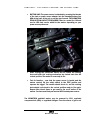
1
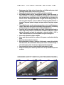
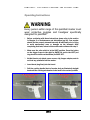
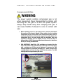
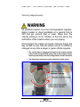
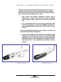
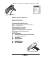
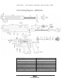
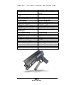
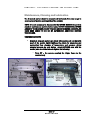
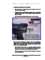
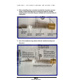
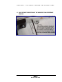
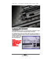
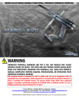
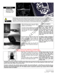
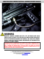
ARMOTECH ZEUS SERIES PAINTBALL MARKER OWNER’S MANUAL WARNING ARMOTECH PAINTBALL MARKERS ARE NOT A TOY. ANY MISUSE MAY CAUSE SERIOUS INJURY OR DEATH. THE USER AND ANY PERSON WITHIN RANGE MUST WEAR EYE PROTECTION DESIGNED FOR PAINTBALL USE. READ THIS OWNER’S MANUAL COMPLETELY BEFORE LOADING, PRESSURIZING, OR OPERATING YOUR ARMOTECH PAINTBALL MARKER. This paintball marker is intended for sale to adults only, for use in compliance with all applicable laws and regulations. Adult supervision is recommended at all times whenever a minor is handling this paintball marker. All persons within range MUST wear protective goggles & headgear specifically designed for paintball when a paintball marker is in use. Paintball safety rules must be followed at all times. ARMOTECH WG065 OWNER’S MANUAL, Compiled for ARMOTECH International, by John L.R. Dovale, Dangerous Enterprises. Imagery by Mark Chance, Island Designs (ala Section 8) Armotech International / Armotech Taiwan Ltd. http://www.armotech.net, 6F No 10 Sec 4 Tzu Chiang Rd, San Chung, Taipei Hsien, Taiwan R.O.C. Technical support forum http://www.armotech.us Table of Contents CHAPTER 1 CHAPTER 3 Paintball Safety Rules 1 Trigger Safe Switch 2 Operating Instructions 3 Compressed Air/Gas 5 CO2 Safety 8 Velocity Adjustment 10 Troubleshooting 26 Tips, Hints ‘n Tricks (from our forum) Warranty Info. 30 CHAPTER 2 ZEUS Series Marker Specifications Parts & Diagram Parts & Diagram G2 Maintenance & Lubrication Cupseal Maint. G2 Barrel Swap 12 13 15 17 21 25 This owner’s manual is provided with several models of the ZEUS series paintball marker. Armotech Inc reserves the right to modify or change its markers without incurring any obligation to incorporate such modifications or changes in any of its products that were sold prior to the modification. The information in this owner’s manual may be updated or changed without notice. This owner’s manual is intended to remain with the paintball marker upon any subsequent transfer of the marker, whether through sale, resale, or furnishing in any manner. ARMOTECH WG065 OWNER’S MANUAL, Compiled for ARMOTECH International, by John L.R. Dovale, Dangerous Enterprises. Imagery by Mark Chance, Island Designs (ala Section 8) Armotech International / Armotech Taiwan Ltd. http://www.armotech.net, 6F No 10 Sec 4 Tzu Chiang Rd, San Chung, Taipei Hsien, Taiwan R.O.C. Technical support forum http://www.armotech.us A R M O T E C H – T H E P E R F E C T M A R K E R … T H E P E R F E C T G A M E 1 Chapter Paintball Safety Rules Safety First! WARNING ARMOTECH PAINTBALL MARKERS ARE NOT A TOY. ANY MISUSE MAY CAUSE SERIOUS INJURY OR DEATH. THE USER AND ANY PERSON WITHIN RANGE MUST WEAR EYE PROTECTION DESIGNED FOR PAINTBALL USE. READ THIS OWNERS’S MANUAL COMPLETELY BEFORE LOADING, PRESSURIZING, OR OPERATING YOUR ARMOTECH PAINTBALL MARKER. • • • • • • • Always wear protective goggles & headgear designed for paintball when shooting this marker Everyone within range of an area where this paintball marker is used should wear protective goggles and headgear specifically designed for paintball Operate this paintball marker only in areas where it is safe and lawful to do so Misuse of this marker may result in criminal charges or imprisonment This marker is intended for sale to adults. Adult supervision is recommended at all times whenever a minor is handling this marker READ THIS OWNER’S MANUAL COMPLETELY BEFORE LOADING, PRESSURIZING, OR OPERATING THE ARMOTECH MARS SERIES PAINTBALL MARKER! Never aim or shoot this paintball marker towards anybody who is not wearing protective goggles or headgear specifically designed for paintball ZEUS 1 A R M O T E C H • • • • • • • • • • • – T H E P E R F E C T M A R K E R … T H E P E R F E C T G A M E During game play, follow referee’s instructions and all field safety rules. Avoid shooting at another player’s head, neck or groin area Play paintball only where the rules of safety for paintball are followed All paintball markers must be chronographed regularly. Adjust the marker to shoot paintballs at a velocity this is 300feet per second (fps) or less and that does not exceed the velocity limit set by the Paintball Park or field where the marker is in use. Chronograph the marker at regular intervals during the day, as well as any time the power source is refilled or changed, any time the barrel or any part of the power system is changed, and upon request of any player or game official This paintball marker operates using compressed gas or air at specified pressure ranges. Follow safety procedures when handling compressed gas or air. All filling of compressed gas or air cylinders must be done by qualified persons Follow the rules of safe marker handling: keep finger off the trigger until ready to shoot. Keep muzzle pointed in a safe direction. In addition, firmly insert a barrel plug into the muzzle and push the mechanical or electronic safety to “ON” or “SAFE” when the marker is not in use and when in any non-shooting area Never shoot at domestic animals or wildlife Never mark objects outside the confines of the game or authorized shooting areas Never look down the barrel of a marker Before disassembly, storage, or transport of this marker, remove ALL paintballs from the marker, barrel, and loader: remove power source: and remove all gas or air from the power system. Insert a barrel plug and put the safety “ON” Carry your marker in a case or sturdy bag when transporting it in public Safely and securely store marker to prevent access to it by unauthorized persons or minors. MARKER SAFETY SWITCH (ON TRIGGER FRAME) ZEUS 2 A R M O T E C H – T H E P E R F E C T M A R K E R … T H E P E R F E C T G A M E Operating Instructions WARNING Every person within range of this paintball marker must wear protective goggles and headgear specifically designed for paintball. 1. Before continuing with these instructions please refer to the section in Chapter 2 on maintenance and lubrication (pg 16). Your marker should first be properly cleaned internally & lubricated prior to firing to avoid unnecessary wear or damage on the internals. After completing that task, return to this section and continue with step 2. 2. Make sure the safe switch is in the SAFE position. Press the button on the trigger frame to the right for SAFE ON, and to the LEFT (red ring should be visible on the button) for SAFE OFF. 3. At this time do not attach power source, clip/hopper adapter, and do not load any paintballs into the marker. 4. Insert barrel plug firmly into the barrel. 5. Pull the cocking handle (back of marker body as illustrated) straight back until the cocking mechanism locks back in the cocked position ZEUS 3 A R M O T E C H – T H E P E R F E C T M A R K E R … T H E P E R F E C T G A M E Turn the safety switch to the FIRE position and then squeeze the trigger with an even pressure. The cocking knob should snap forward into the un-cocked position. You have just dry-fired your Armotech marker. Do this a few times until you are comfortable with this operation and the feel of the marker when cocking, and firing it. 6. Using the supplied hex-wrench make certain to properly tighten all screws on your marker. These include the trigger frame and bottom line if you have outfitted your ZEUS with that upgrade module. Do not overtighten and take care not to strip ANY of these screws. 7. Attach the ammo/ball clip to the top of the marker. Depending on how your clips are configured they may insert differently. The ARMOTECH clips insert by sliding the front section of the clip into the milled groove at the top-front section of the receiver body. Apply a slight forward pressure and snap the rear section of the clip into place (see illustration below). 8. If your clip inserts from the rear, simply repeat the process but this time insert the clip into the rear groove at the top of the receiver body, while pulling the other retainer clip back slightly with your fingers so it snaps into position ZEUS 4 Revision 2 Dec 2003 A R M O T E C H – T H E P E R F E C T M A R K E R … T H E P E R F E C T G A M E Compressed Air/Gas WARNING The power system contains compressed gas or air when pressurized. Never disassemble the marker until removing ALL the gas or air from the power system. Always keep hands away from escaping CO2 gas. It can cause frostbite if allowed to come in contact with skin. • Before attaching any air or gas power source, read and understand this section of the owner’s manual. Follow safety rules for handling compressed air/gas. If any leaks occur in the power system, refer to troubleshooting section or Armotech support. Use only cylinders for compressed gas or air that comply with all applicable laws and regulations, including but not limited to those of the US dept of transportation, OSHA, Compressed Gas Association and/or American Society for Testing and Materials. • CO2 CARTRIDGE: Small 12gr. CO2 cartridges are inserted into the front of the marker body, just below the barrel and secured into place with a retainer cap. As the cap is tightened, it presses the CO2 cartridge against a specialized activation pin – which punctures the cartridge head, and starts the flow of CO2 into the marker. The CO2 cartridge delivers approximately 22 shots. ZEUS 5 Revision 2 Dec 2003 A R M O T E C H • – T H E P E R F E C T M A R K E R … T H E P E R F E C T G A M E BOTTOM LINE: The power source is attached by screwing the threads of the tank or power source adapter into the threaded bottom line ASA at the base of the grip or on the drop forward. THE ARMOTECH ZEUS BOTTOM LINE KIT IS REQUIRED! There is a model for CO2 and one for HPA that can be added to the marker depending on your power source preference. • • When cocking the pressurized marker do not release the cocking knob until after the cocking mechanism has locked back into the cocked position. The marker is now ready to fire. • Test for function – now that the power source is loaded and the marker cocked, flip the safety switch to the FIRE position and squeeze the trigger. The marker should shoot air, and the cocking knob should cycle back to the cocked position ready to fire again. Repeat this several times to get used to the recoil action of the marker. You have now fired your marker WITH loaded power source. The ARMOTECH paintball marker may be powered by CO2, regulated compressed air (HPA), or regulated nitrogen. From the source of gas or air ZEUS 6 Revision 2 Dec 2003 A R M O T E C H – T H E P E R F E C T M A R K E R … T H E P E R F E C T G A M E through the entire power system, there are varying pressures that are applied to the marker and the components of the power system. The marker requires a minimum of 450psi for proper operation If you are using HPA please ensure that the HPA bottle regulator output is at least 550 PSI. ZEUS 7 Revision 2 Dec 2003 A R M O T E C H – T H E P E R F E C T M A R K E R … T H E P E R F E C T G A M E SAFETY RULES FOR HANDLING COMPRESSED AIR OR GAS MUST BE FOLLOWED AT ALL TIMES! OPERATING PRESSURES AND INPUT PRESSURE • Operating pressure range 450 p.s.i. to 900 p.s.i. (Although some markers have been known to operate at pressures as low as 330 p.s.i. or pressures over 1100 p.s.i. it is recommended that the specified operating pressure of the Armotech marker be used in order to avoid problems.) • Never exceed recommended pressures, as this may be dangerous to you and damaging to the marker. • Do not leave a pressurized marker or cylinder in direct sunlight or exposed heat source. Increased temperatures will increase the internal pressure of the compressed gas or air and could cause problems. NOTES FOR BOTTOM LINE ADAPTED ZEUS PISTOL MARKERS ONLY! VALVE CYLINDER CONNECTION The Valve on a cylinder is to remain screwed into the cylinder. Should it loosen, the cylinder may detach from the valve with an extremely dangerous force. • Every time a cylinder is filled, the connection between the valve and cylinder must be inspected. If any looseness or leak is detected between the valve and the cylinder, do not fill. Drain the cylinder and have it inspected by qualified persons. • During filling if any looseness or leak is detected between the valve and the cylinder, filling should be stopped and the cylinder should immediately be drained to avoid problems. FILLING COMPRESSED AIR/GAS • An overfill of any compressed air or gas cylinder can cause the safety burst disk on the cylinder to rupture. A cylinder may rupture with excessive force. Use properly rated disk only for the burst disk. • A scale must be used for ALL CO2 fills to prevent an overfill. A pressure gauge must be used for all compressed gas or air fills to prevent overfills. ZEUS 8 Revision 2 Dec 2003 A R M O T E C H – T H E P E R F E C T M A R K E R … T H E P E R F E C T G A M E • Many cylinders are required to have US Department of Transportation hydrostatic tests done at periodic intervals. This interval varies depending on the cylinder type. The date of the cylinder’s initial or last testing appears on the cylinder. Out of date cylinders should not be used. • Installing the Gas/Air Power Source o Make sure the BARREL PLUG is placed in the barrel o Put the trigger frame on SAFE o Screw the compressed air/gas source into the ASA Bottom line Adapter o Tighten until you feel a solid stop o Turn the gas/air on if it has an on/off valve, otherwise it should be active and ready to go. o Do not store the marker with power source installed and full • Removing the Gas/Air Power Source o Always remove power source before performing disassembly of marker o Unload all paint from the marker and detach the hopper/loader o Put the trigger frame on SAFE, o Slowly unscrew the CO2 Cartridge retainer cap to release remaining CO2 pressure, discard the canister once empty. • IF USING A BOTTOM LINE CONTINUE BELOW o If the power source has an on/off valve – shut it OFF. Otherwise point the marker in a safe position and slowly unscrew the power source. o You will hear some compressed gas/air escaping via a bleedhole while unscrewing the power source. If you prefer you can fire the marker to release ANY pressure in the system, while continuing to unscrew the power source. o If the unscrewing is difficult the system still has too much pressure in it – check to make sure the power source is OFF (if it has an on/off valve), or to ensure it is completely discharged before continuing. CO2 can cause damage to Orings. These need to be inspected regularly to avoid leaks. ZEUS 9 Revision 2 Dec 2003 A R M O T E C H – T H E P E R F E C T M A R K E R … T H E P E R F E C T G A M E Velocity Adjustments WARNING All paintball markers must be chronographed regularly. Adjust marker to shoot paintballs at a velocity that is 300 feet per second (fps) or lower. Make sure the velocity setting is not in violation of the limit set by the authorities of the location where you are playing. Chronograph the marker at regular intervals during the day as well as any time the power source is refilled or changed or any time a player or game official requests. • The velocity knob is located at the back on the receiver (marker body). On the Armotech ZEUS marker this velocity adjuster can be turned by hand easily once the locking retainer screw is loosened. • The illustrations below show how to adjust the velocity screw. ZEUS 10 Revision 2 Dec 2003 A R M O T E C H – T H E P E R F E C T M A R K E R … T H E P E R F E C T G A M E To adjust velocity after loosening the locking retainer screw, turn the velocity screw clockwise in ½ turn increments. To decrease velocities turn the velocity screw counter-clockwise. Once the desired velocity has been reached, lock the velocity screw in place. • Note: velocity may fluctuate depending on factors such as altitude, type of power source used, and climate conditions. Before using your marker make sure to perform a safe velocity test. • Use a chronograph and let’s ensure we are within the safely allowable velocity range. Velocity should NEVER exceed 300 f.p.s. Some paintball fields may require your marker to be set under 300 f.p.s. Once you have achieved the proper velocity setting – you can lock it in place with the Velocity Locking Screw. • Velocity of the marker can also be affected or controlled by the settings of the regulated air/gas supply. On the Armotech ZEUS marker this is not an issue unless you are using the bottomline HPA adapter (photo on left bottom) as this is a regulated input. In those cases, refer to the manufacturer instructions for those products. HPA Bottom Line Kit CO2 Bottom Line Kit ZEUS 11 Revision 2 Dec 2003 A R M O T E C H – T H E P E R F E C T M A R K E R … T H E P E R F E C T G A M E 2 Chapter ZEUS Series Marker Specifications 1. Lightweight Aluminum Milled Receiver Body 2. Semi – composite trigger frame with contoured rubber grips 3. Quick strip Field Maintenance 4. Rear Velocity Adjustment (200-350fps) 5. CO2 Cartridge power source system 6. Bottom Line ASA Adapter compatible (optional hardware) 7. Hopper adapter compatible (optional hardware) 8. Ported barrel 9. Rear Cocking Blowback 10. Vertical Ball Feeding from spring loaded clip above receiver 11. Plate with Ball-Bearing Ball Detent 12. .689 Caliber Bore 13. G2- lighter body design 14. G2-Quicker Reloads 15. G2-Integrated R.I.S. Rail 16. G2-8” Extension Barrel ZEUS 12 Revision 2 Dec 2003 A R M O T E C H – T H E P E R F E C T M A R K E R … T H E P E R F E C T G A M E Parts Listing & Diagrams (ZEUS Standard) 1. Receiver Body 3. Mid Section Receiver Strength Plate 5. Bottom Line adapter screw 7. valve copper retainer screw 9. Delrin venturi bolt 11. Cocking Handle 13. (0-13) Striker O-ring 15. Striker Spring 17. Striker Spring Tension Guide 2. Vertical Power access screw 4. hex Nuts for Strength Plate 6. Hex retainer lug for volumeizer insert 8. Valve Pin 10. Venturi/Striker connection rod 12. Cocking Handle retainer screw 14. Striker Body 16. Striker Rubber Buffer 18. Striker Rear Cap/Vel. Adj. Cap ZEUS 13 Revision 2 Dec 2003 A R M O T E C H – T H E P E R F E C T M A R K E R … T H E 19. Velocity Adjuster Thumbscrew 21. Ball Detent Screws (21-1) washers 23. Ball Detent Pin 25. Front face-plug retainer screw 27. Retainer Pin c-clips 29. Tension Spring 31. Tension Spring Adjust Handle 33. Plug –pull ring (metal) 35. Trigger Frame GRIP 37. Trigger Frame Screws (37-1)washers 39. Safety Plug ball bearing roller 41. CO2 cartridge retainer plug 43. Co2 volumizer housing 45. cupseal 47. (0-47) Valve o-rings 49. trigger retaining pin 51. trigger return tap(forward sear) 53. sear tension recoil spring 55. sear spring retainer clip 57. forward sear spring retainer pin P E R F E C T G A M E 20. (0-20) Thumbscrew o-ring 22. Ball Detent Plate 24. Ammo Clip Front Face-plug 26. Ammo Clip Retainer Pins 28. Ammo Clip Housing 30. Tension Spring Head 32. Quick Load Plug 34. Composite Trigger Frame 36. GRIP screws 38. Safety On/OFF plug 40. Safety Switch Tension Spring 42. Co2 cartridge puncture plate 44. cupseal spring 46. valve pin 48. Turbo Valve Assembly 50. trigger 52. trigger tension recoil spring 54. SEAR 56. sear retainer clip 58. upper trigger assembly retainer pin NOTE: Note differences between standard Zeus and Zeus G2 – The G2 has a small removable barrel at the front and comes with an interchangeable 8” barrel extension – The G2 has different porting on the receiver barrel – The G2 has a different co2 cartridge retainer plug - The G2 is lighter. G2 uses ball bearing detent ZEUS 14 Revision 2 Dec 2003 A R M O T E C H – T H E P E R F E C T M A R K E R … T H E P E R F E C T G A M E Parts Listing Diagram – (ZEUS G2) 1. Receiver Body 3. 1” Barrel Nun 5. Bottom Line adapter screw 7. valve copper retainer screw 9. Delrin venturi bolt 11. Cocking Handle 13. (0-13) Striker O-ring 15. Striker Spring 17. Striker Spring Tension Guide 2. Vertical Power access screw 4. 8” Extension Barrel (not drawn) 6. Hex retainer lug for volumeizer insert 8. Valve Pin 10. Venturi/Striker connection rod 12. Cocking Handle retainer screw 14. Striker Body 16. Striker Rubber Buffer 18. Striker Rear Cap/Vel. Adj. Cap ZEUS 15 Revision 2 Dec 2003 A R M O T E C H – T H E P E R F E C T M A R K E R … T H E 19. Velocity Adjuster Thumbscrew 21. N/A 23. Detent threaded housing in receiver (rh side) 25. Front face-plug retainer screw 27. Retainer Pin c-clips 29. Tension Spring 31. Tension Spring Adjust Handle 33. Plug –pull ring (metal) 35. Trigger Frame GRIP 37. Trigger Frame Screws (37-1)washers 39. Safety Plug ball bearing roller 41. CO2 cartridge retainer plug & tightening tool 43. C)2 volumizer housing 45. cupseal 47. (0-47) Valve o-rings 49. trigger retaining pin 51. trigger return tap(forward sear) 53. sear tension recoil spring 55. sear spring retainer clip 57. forward sear spring retainer pin P E R F E C T G A M E 20. (0-20) Thumbscrew o-ring 22. Ball Detent (EVO style with ball bearing) 24. Ammo Clip Front Face-plug 26. Ammo Clip Retainer Pins 28. Ammo Clip Housing 30. Tension Spring Head 32. Quick Load Plug 34. Composite Trigger Frame 36. GRIP screws 38. Safety On/OFF plug 40. Safety Switch Tension Spring 42. Co2 cartridge air-puncture plate 44. cupseal spring 46. valve pin 48. Turbo Valve Assembly 50. trigger 52. trigger tension recoil spring 54. SEAR 56. sear retainer clip 58. upper trigger assembly retainer pin ZEUS 16 Revision 2 Dec 2003 A R M O T E C H – T H E P E R F E C T M A R K E R … T H E P E R F E C T G A M E Maintenance, Cleaning and Lubrication The Armotech marker should be cleaned and lubricated after every usage to ensure proper function and longevity of the product. NOTE: It is not necessary to disassemble the ENTIRE MARKER to perform standard maintenance and lubrication tasks. DO NOT DISASSEMBLE OTHER AREAS OF THE MARKER UNLESS YOU ARE AN EXPERIENCED AIRSMITH, OR HAVE BEEN ASKED TO DO SO BY AUTHORIZED ARMOTECH SERVICE TECHNICIANS. TIGHTENING SCREWS • Armotech ships all markers pre-lubed with machine oil only but with most of the screws lightly tightened to allows for expansion and contracting from changes of temperature and pressure during shipping process. As such before doing ANYTHING else with the marker, care should be taken to tighten the following: o Parts 37 – the screws securing the trigger frame to the receiver body ZEUS 17 Revision 2 Dec 2003 A R M O T E C H – T H E P E R F E C T M A R K E R … T H E P E R F E C T G A M E CLEANING AND LUBRICATION OF INTERNALS • Remove the striker cap/velocity adjustment assembly at the back of the marker by unscrewing it. • Cock the marker by pulling back the cocking handle. Do it carefully so that it slowly ejects the striker guide and spring. Remove the guide and spring • Remove the Venturi bolt by pulling it out the back of the marker With the internals removed you should be able to look through the receiver body. In the top tube you should see the ball detent slightly sticking out. In the bottom tube you should see the back of the valve with the valve pin sticking through it. • With all the internals removed, run a squeegee through the receiver body to clean it out – it is recommended that a latex/proflex squeegee be used for this to avoid damage to the ball detent • The same squeegee can be reused (after cleaning it) to clean the barrel of any residuals ZEUS 18 Revision 2 Dec 2003 A R M O T E C H – T H E P E R F E C T M A R K E R … T H E P E R F E C T G A M E • The receiver body can be cleaned with a soft rag and warm water (careful not to get any on the electronics of the trigger frame if the marker has an e-trigger) or with a solvent such as WINDEX, which dissolves the paintball residue nicely. DO NOT USE WINDEX TO CLEAN YOUR GOGGLES. FOLLOW THE MANUFACTURERS RECOMMENDATIONS FOR THAT PRODUCT! • Use warm, water or Windex to clean the venture bolt, and striker of any residue and dry them with a lint free cloth. • Once dry, check the o-rings for any damage or loose fit. If you believe the o-ring to be damaged or fitting loosely – replace it immediately. Do not use the rubber bottle o-rings on your striker or barrel. Use only the Urethane or Teflon o-rings for this purpose. • Also check the o-ring on the velocity adjuster cap to ensure it’s not damaged. • Before re-assembling the internals, it is recommended that these be properly lubricated. ONLY PAINTBALL GUN LUBRICATION is recommended. DO NOT lubricate your internals with WD-40. Acceptable lubricants are also TEFLON GREASE, SILICON GREASE. • Lubricate ONLY the sections of the venturi bolt and striker where the o-ring is fitted. These are the only sections which make physical contact with the sidewalls of the receiver internally. ZEUS 19 Revision 2 Dec 2003 A R M O T E C H – T H E P E R F E C T M A R K E R … T H E P E R F E C T G A M E • There are no o-rings on the ZEUS delrin bolt but and 1 on the striker The shaft of the delrin venture should be fully lubricated. • Re-insert the striker and bolt assembly, making certain to orient the striker with the flat grooved section pointed down towards the trigger frame – this is the section that locks the assembly in place when the marker is cocked. • On inserting the striker/bolt assembly it may seem to JAM- this is the SEAR which is stopping it from passing – NOTE: Pull the trigger to allow the striker to bypass the sear on the SEMI trigger frame. • Once the assembly is inserted, insert the striker buffer into the marker, and insert the striker spring into the center of the buffer until it contacts with the striker itself • Replace the Velocity Adjustment Cap • Once this task is completed you have successfully maintained the core section of your marker. • UNLESS YOU HAVE LEAKS THE INTERNALS (BOLT/STRIKER) ARE THE ONLY SECTIONS THAT SHOULD BE REMOVED FROM THE MARKER ON A REGULAR BASIS FOR CLEANING. • NEVER LET PAINT RESIDUE SIT IN THE MARKER OVERNIGHT – THE CHEMICAL WILL ERODE THE O-RINGS. ZEUS 20 Revision 2 Dec 2003 A R M O T E C H – T H E P E R F E C T M A R K E R … T H E P E R F E C T G A M E BELOW IS A RECOMMENDED LIST OF ITEMS WHICH SHOULD BE KEPT AS SPARES, OR REPLACEMENT PARTS FOR YOUR ARMOTECH MARKER Teflon or Urethane O-rings Rubber bottle and ASA O-rings ARMOTECH spare parts/spring kit Replacement cup seal (original or a black magic) REMOVING AND SERVICING CUP SEAL 1. Remove part #06 the hex retainer screw at the bottom of the receiver just forward of the trigger-frame ZEUS 21 Revision 2 Dec 2003 A R M O T E C H – T H E P E R F E C T M A R K E R … T H E P E R F E C T G A M E 2. Insert a smaller sized allen wrench into the hole where the lug (part #6) came out, and and use it to gently push the CO2 volumize housing outward gently. (parts #42 & 43) 3. Once this part is out, the cupseal, valve stem, spring will all easily be removed for service. ZEUS 22 Revision 2 Dec 2003 A R M O T E C H – T H E P E R F E C T M A R K E R … T H E P E R F E C T G A M E 4. When reinstalling please remember to install the valve-stem/cup seal, spring, volumizer housing (copper looking piece) and Co2 cartidge puncture plate in that order. Improper assembly will cause the marker to malfunction. 5. Use a flat screwdriver (long stem) to slide the volumizer housing back into place. ZEUS 23 Revision 2 Dec 2003 A R M O T E C H – T H E P E R F E C T M A R K E R … T H E P E R F E C T G A M E 6. ONLY SERVICE THIS SECTION OF THE MARKER IF YOU EXPERIENCE LEAKING . ZEUS 24 Revision 2 Dec 2003 A R M O T E C H – T H E P E R F E C T M A R K E R … T H E P E R F E C T G A M E ATTENTION ZUES G2 OWNERS ONLY! On the ZEUS G2 model marker, you have the option of using the 1” barrel nub, or an 8” barrel extension for increased range and accuracy. The illustration (above) shows the marker with the small nub installed. To uninstall simply unscrew the nub by turning it counterclockwise until it is completely removed. You can then replace it with the 8” barrel extension. IT IS NOT RECOMMENDED TO USE THE MARKER WITHOUT THE NUB OR EXTENDED BARREL AS IT MAY DECREASE PERFORMANCE. ZEUS 25 Revision 2 Dec 2003 A R M O T E C H – T H E P E R F E C T M A R K E R … T H E P E R F E C T G A M E 3 Chapter Troubleshooting Tips, Hints ‘n Tricks • Marker not firing: o Check to ensure there is a full CO2 cartridge in the marker. If you are using a bottom line and external power source, check to ensure its turned ON and has sufficient PSI to operate the marker. o Check to ensure the marker is cocked o Check to ensure the safe switch is in LIVE FIRE mode (switched to the left) (ALL MODELS. • I hear a hissing sound when I attach the power source: o ONLY Load CO2 cartridges with the marker in COCKED position, or CO2 will escape. o If using a bottom line, check the o-ring on the air supply bottle – it may not look worn but could be – and will leak o If leak is not at bottle attachment, check the connection point for the bottom line adapter in the CO2 chamber of the marker – it may not be properly seated- tighten the retainer lug to seat it, or use some lubricant to ensure its not a leak due to dry o-rings o Check the o-rings on the bottom line chamber to ensure they are not damaged o If none of these sections are leaking, check the cup-seal to make sure it is sitting properly against the valve. This is easily replaced with an Armotech cup-seal or any spyder compatible equivalent – ZEUS 26 Revision 2 Dec 2003 A R M O T E C H – T H E P E R F E C T M A R K E R … T H E P E R F E C T G A M E the BLACK MAGIC cup-seal is highly recommended to cure cupseal leaks. • I cannot cock the marker: o Remove the velocity adjuster cap and examine the striker pin section to ensure it is assembled properly o Check the hex screw at the back of the trigger frame as it may be too tight and causing a misalignment problem o If this jam occurred after a ball break, carefully check to ensure there is residual skin fragments of the ball stuck between the receiver housing and the barrel o If this jam occurred not from a ball break, carefully disassemble the internals and check to see if the o-rings are not dislodged or broken • The marker shoots once and does not re-cock: o The o-ring on the striker hammer could be damaged and needs replacing o Check the cup seal to ensure the whole assembly is sitting properly and is not leaking o Check your air supply to ensure you have sufficient pressure to operate the marker • The marker fires and continues to rapid fire, the re-cock does not hold: o The sear adjustment is too low – check the section on trigger adjustments and make the appropriate changes to correct the problem o Check the screws which hold the trigger frame to the receiver – if they are loose – tighten them, in particular the rear screw • The marker requires multiple trigger pulls to fire once: o Trigger recoil springs may be dislodged or broken and not returning trigger to full frontal position which engages the sear for the next trigger pull. Trigger disassembly and checking will be required. ZEUS 27 Revision 2 Dec 2003 A R M O T E C H – T H E P E R F E C T M A R K E R … T H E P E R F E C T G A M E o Balls break in the breach when attempting rapid firing: o Check to ensure the ball-clip is seated properly o Check to ensure the loader cap is not blocking flow of balls into breach at the rear of the clip o Check the clip ball breach opening to ensure balls are passing smoothly and not jamming (this could happen if balls are too big, or if they are mal-formed from swelling). o Check the spring loaded clip ball feed – spring maybe too weak o Balls may be too small and when fed into breach the waiting ball is half way down and gets chopped when trigger is pulled. Recommended bore is .688/.690 for the ZEUS • Balls are not flying straight when fired: o Clean the barrel with a squeegee o Make sure the balls are the correct size/caliber for the bore of the marker .689 • Balls roll out of the barrel or shoots 2 at a time: o Ball bore is too small. It needs to be .689 o Armotech recommends using tournament quality paint • RPS / PMI Brand (Big Ball/Warrior, El Tigre, Slam, All Star, Premium, Premium Gold, Marballizer) TC Paintballs (Viper Venoms, Viper Platinum, Pro Series) Nelson Paintballs (Nel Splat, Anarchy, Nelson Gold) PowerBall Paintballs Barrel threads look worn down and barrel wobbles a bit (G2 model only) o Check to ensure barrel o-ring is in place properly o Always use some grease type lubricant on the threads to avoid metal-to-metal wear ZEUS 28 Revision 2 Dec 2003 A R M O T E C H • – T H E P E R F E C T M A R K E R … T H E P E R F E C T G A M E Balls shoot but they do not appear to go the distance: o Adjust the velocity and check it with a chronograph o Check to ensure the striker spring is not damaged, weakened or broken o Check your air supply to ensure there is sufficient pressure o Check to ensure regulator settings are properly adjusted. Min pressure should not be less than 450 p.s.i. on the HPA bottom line if you have that installed. ZEUS 29 Revision 2 Dec 2003 A R M O T E C H – T H E P E R F E C T M A R K E R … T H E P E R F E C T G A M E Warranty Information Warranty Information LIMITED LIFETIME WARRANTY This product is warranted to the retail consumer for lifetime from the date of purchase against defects in material and workmanship and is non-transferable. To register the serial number of your Armotech Paintball Marker, please return the product registration form in your owner’s manual packet. The warranty however, is not conditional on the return of the card. WHAT IS COVERED Replacement parts are covered under the warranty. Transportation charges to the consumer for any repaired product are also covered. WHAT IS NOT COVERED Transportation charges to ARMOTECH USA (www.armotech.us) for any returned product with RMA. Damage caused by abuse or failure to perform normal maintenance as per the user manual. Any other expense above and beyond this warranty. CONSEQUENTIAL DAMAGES, INCIDENTAL DAMAGES, INCIDENTAL EXPENSES, INCLUDING DAMAGE TO PROPERTY. SOME STATES/COUNTRIES DO NOT ALLOW THE EXLUSION OR LIMITATION OF INCIDENTAL OR CONSEQUENTIAL DAMAGES; THEREFOR THE ABOVE LIMITATIONS OR EXCLUSIONS MAY NOT APPLY. WARRANTY CLAIMS USA based clients: Attach your name, address, description of problem, phone number, and copy of sales receipt for the product. Package and return to : ARMOTECH US P.o.Box 607 Berlin NJ, 08009 International customers please return product to your nearest regional distributor. If you are not familiar with the nearest distributor to your area, please call 1.856.753.2662 and ask for our International Department. IMPLIED WARRANTIES ANY IMPLIED WARRANTIES, INCLUDING THE IMPLIED WARRANTIES OF MECHANTABILITY AND FITNESS FOR A PARTICULAR PURPOSE, ARE LIMITED IN DURATION TO LIFETIME FROM THE DATE OF RETAIL PURCHASE. SOME STATES DO NOT ALLOW LIMITATIONS ON HOW LONG AN IMPLIED WARRANTY LASTS, THEREFORE THE ABOVE LIMITATIONS MAY NOT APPLY. To the extent any provisions of this warranty are prohibited by Federal, State or Municipal Law which cannot be preempted, it shall not be applicable. The warranty gives you specific legal rights, and you may also have other rights which vary from state to state and country to country. ZEUS 30 Revision 2 Dec 2003 A R M O T E C H – T H E NOW ALSO P E R F E C T M A R K E R … T H E AVAILABLE P E R F E C T FOR G A M E PURCHASE ZEUS G2 LIMITED EDITION Marker is the standard ZEUS G2 unit with additional barrel extension (baffle) unit, bottom line kit, laser pointer kit, hopper attachment kit, quickload clip adapter kit, and the T-stock, all packed into a hardened aluminum carry case. ZEUS 31 Revision 2 Dec 2003 A R M O T E C H – T H E P E R F E C T M A R K E R … T H E P E R F E C T G A M E SUGGESTED ITEMS FOR PROPER MAINTENANCE Rod Squeegee with Swab on the end Cleaning cloths (soft terry-cloth material) Paintball Marker Lubrication (OIL designed for paintball markers , or Teflon /Silicon grease) o-ring and spring replacement kit (as a spare) hex-wrenches of various sizes (marker comes with most commonly needed ones) Barrel Plug or Condom RECOMMENDED UPGRADES Additional paintball ammo clips Quick-Load adapter for ammo clips 10-round ball pods Bottom line adapters (if this is your main marker) ZEUS 32 Revision 2 Dec 2003