1
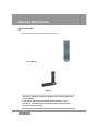
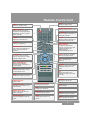
SAB SAFIR
Users Manual
Please read this users manual carefully.
The menu structure and specifications can be changed without notice.
Contents
General Information -------------------------------------------------------------------- 3
Safety and Precaution ----------------------------------------------------------- 3
Accessories ------------------------------------------------------------------------ 5
Remote Control Unit ------------------------------------------------------------------- 6
System Connection -------------------------------------------------------------------- 7
Front Panel ------------------------------------------------------------------------- 7
Rear Panel ------------------------------------------------------------------------- 8
Connecting your System -------------------------------------------------------- 9
Menu Structure ------------------------------------------------------------------------- 11
Menu Guide ------------------------------------------------------------------------------ 12
Installation ------------------------------------------------------------------------ 12
Channel Guide ------------------------------------------------------------------ 19
Channel Manager --------------------------------------------------------------- 22
System Setting ------------------------------------------------------------------ 25
Embedded CAS ----------------------------------------------------------------- 29
Functions Guide ----------------------------------------------------------------------- 30
List Menu -------------------------------------------------------------------------- 30
Info Bar ---------------------------------------------------------------------------- 32
Signal ------------------------------------------------------------------------------ 32
Zoom ------------------------------------------------------------------------------- 33
Quick Edit ------------------------------------------------------------------------- 33
Audio Language ----------------------------------------------------------------- 33
PIP ---------------------------------------------------------------------------------- 34
Technical Specification ------------------------------------------------------------- 35
Trouble Shooting Guide ------------------------------------------------------------ 37
2
General Information
Safety and Precautions
Thank you for purchasing the digital satellite receiver.
For your safety and proper operation, please take time reading this manual fully before
installing and operating the receiver.
We hope you will be able to take advantage of the numerous functions with the help of
this manual.
◈ MAINS SUPPLY
Use only 100 - 250VAC 50/60Hz.
◈ OVERLOADING
Do not overload a wall outlet, extension cord or adapter as this may result in fire
electric shock.
◈ LIQUIDS
Do not be exposed to dripping or splashing and that no objects filled with
liquids, such as vases, shall be placed on the apparatus.
◈ CLEANING
1. Always disconnect the STB power cord from the outlet before cleaning.
2. Use a light damp cloth (no solvents) to dust off the STB.
◈ VENTILATION
1. The slots on top of the STB must be left uncovered to allow proper airflow to
the unit.
2. Do not stand the STB on soft furnishings or carpets.
3. Do not expose the STB to direct sunlight or do not place it near a heater.
4. Do not stack electronic equipments on top of the STB.
5. Do not use this appliance in airtight area.
6. Do not open the top cover.
◈ CABLE
Use standard certified cables to prevent any malfunction of the STB.
3
General Information
Safety and Precautions
◈ ATTACHMENTS
Do not use any attachments that are not recommended as these may cause
hazard or damage to the STB.
◈ CONNECTION TO THE SATELLITE DISH LNB
Disconnect the STB from the mains before connecting or disconnecting the
cables from the satellite dish.
Failure to do so can damage the LNB.
◈ CONNECTION TO THE TV
Disconnect the STB from the mains before connecting or disconnecting the
cables from the TV.
Failure to do so can damage the TV.
◈ EARTHING
The LNB cable MUST BE EARTHED to the system earth for the satellite dish.
The earthing system must comply with SABS 061.
◈ LOCATION
Place the STB indoor in order not to expose to lightening, rain or sunlight.
◈ SERVICING
1. Do not attempt to service this product yourself.
2. Refer all servicing to qualified service representatives
NOTICE : The power remains on even when the switch is turned off.
4
General Information
Accessories
Check the following accessories when you open the box
User’s Manual
RCU
Batteries
The device, packaging material and batteries must never be disposed of
with household.
Please obtain appropriate information about regulations in your
community, and dispose of all in accordance with regulations at the
separate locations provided.
5
Remote Control Unit
MUTE
Enable or disable audio
Power
Power on, standby mode.
MOSAIC (Multi Picture)
Display multi channel on screen.
NUMERIC KEYS :
Select channels by channel
numbers or enter programming
parameters. And then inserted
direct character.
TV / RADIO
Receiver switches between TV
and Radio channels.
TIMER
Display the reservation list
TV/SAT
Receiver switches between TV
and Satellite receive mode.
SAT LIST
Display the satellite list
VOL Up/Down
(Page Up/Down)
Increase or decrease the
volume. And move left or right
highlight marked cursor.
Page scrolling in
channel/satellite list menu.
FAV (Favorite)
Set receiver to favorite service
mode, display the favorite
channel.
GUIDE Display the TV/Radio
Electronic Program Guide
CH Up/Down
Tune to the next or previous
channel. And move up or down
highlight marked cursor.
EXIT Cancel the user
selection
INFO (INFORMATION)
Display channel status or
various program information of
current service.
CURSOR
Move up , down , left and right
highlight marked cursor in
menu
MENU
Display the Main Menu, return
To the previous menu
OK
Select menu option, or to
updated on entry and to enter
List menu
FIND
Quick Edit, Find(Sort) CH.name
CH LIST
Display the channel list
PAUSE (Red Key)
Pause screen.
ZOOM (Green Key)
Operated zoom function in live
and still mode
PIP (Picture-in-Picture)
Display the multi picture.
LIST
Display the channel list.
AUDIO (Yellow Key)
Select audio mode (left, right,
stereo, language)
POSITION
Select the display position.
SLEEP (Blue Key)
Operate sleep(auto power off)
mode
SWAP
Swapping the main or sub
picture.
TEXT
Show Teletext
F1
Signal
Display the signal and quality
Recall
Return to status or channel
6
System Connection
Front Panel
◈ Normal Display :
- On
- STANDBY
- Channel Number
- Channel Name
◈ Tact switch : Standby On/Off, CH UP/DOWN, VOL UP/DOWN, MENU, OK
◈ Smart Interface slot : 1 Smart card slot (OPTIONAL)
NOTICE :
1. Current time is based on the TDT(Time and Date Table) at the stream of the
current service. If the TDT information is not correct, current time might be
incorrect.
2. Please do not insert metal or alien substance into the slot for the modules
and Smartcards. In doing so can cause damage to the STB and reduce its life
span.
7
REAR PANEL
Rear Panel
S/PDIF
①② ③
④
⑤ ⑥ ⑦⑧
⑨
Please refer to the diagram above for all possible connections of your receiver
Do not connect the unit to the mains socket until all other connections
have been made and checked.
① IF INPUT : This port is to connect the coaxial cable from LNB of your Dish.
② IF OUT : This enables the connection of an Analogue receiver.
③ VCR SCART : This Scart connector is used to connect any external video.
④ TV SCART : This is used to connect your TV through Scart cable
⑤ VIDEO : This RCA connector is used to connect your TV through RCA cable.
⑥ AUDIO R/L : These RCA connectors are used to connect your TV through
RCA cable or any external audio amp or system
⑦ RF LOOP IN : To connect the terrestrial antenna
⑧ TV OUT : To connect the RF signal to a RF(ANT) input e.g. VCR, TV
⑨ RS 232C SERIAL PORT : This is used to connect your receiver with a
computer or other STB through a serial cable.
8
System Connection
Connecting Your System
◈ TV Only
There are two ways to connect the STB to your existing TV system. We
recommend using one of the following cases for the best result :
y Connect one end of RCA and SCART cable (Composite Video, Audio Left, Right) to
the RCA(SCART) jack on the back of the STB and the other end to a RCA(SCART)
jack on your TV.
y Or connect one end of a component SCART jack on the back of the STB and the
other end to a Component input of your TV.
y Finally connect the coaxial cable from the LNB to the LNB IN jack on the STB.
◈ With External Audio / Hi-Fi System
y To connect any external Audio Hi-Fi system, the receiver has been provided
with two RCA connectors at the back of the receiver marked with Audio L
and R.
y Connect an RCA stereo cable from the AUDIO L, R jacks on the back of the
STB to the LINE, AUX, SPARE OR EXTRA input jacks on your Hi-Fi System or
for better quality connect the S/PDIF output to the S/PDIF input of the Hi-Fi
system
9
System Connection
Connecting Your System
◈ TV with Motorized System (DiSEqC 1.2)
There are two ways to connect the STB to your existing TV system.
We recommend using one of the following cases for the best result
y Connect one end of RCA cable to the RCA jack on the back of the STB and the
other end to a RCA jack on your TV.
y Or connect one end of Scart cable to the Scart jack on the back of the STB and the
other end to a Scart jack on your TV.
y Connect one end of your coaxial cable to the LNB IN connector on the STB and the
other end to the REC or Receiver connector on the DiSEqC 1.2 motor.
y Connect the coaxial cable from the LNB to the LNB connector on the DiSEqC 1.2
motor.
◈ Reference
DiSEqC 1.0/1.1/1.2 Connection
All our receivers are designed to be DiSEqC 1.0 and DiSEqC 1.2 compatible.
This allows multiple antennas to be connected to the STB at the same time.
If you have two or more fixed antennas or LNBs, then we recommend you use a
DiSEqC 1.0 switch.
Connect the coaxial cable from the first LNB to the LNB 1 or LNB A input connector
of the DiSEqC switch.
Do the same for any other LNBs that you have.
Connect one end of a coaxial cable to the RF output connector of the DiSEqC
switch, connect the other end to the LNB IN socket on the STB.
To the digital receiver, you can connect either a single satellite antenna directly or
LNB of multi-feed equipment.
10
Menu Structure
Delete Channel
Main
MainMenu
Menu
Default Configuration
Factory Reset
Program Guide
Channel/TP Data Receive
Software Receive
Channel Guide
Channel Manager
Favorite Channel
Loader Receive
TV/Radio Channel
Send Data
Multi Picture
Favorite Group
OSD Menu
Audio Language
Audio 2’nd
Channel Delete
Channel Sort
Ttxt/Subt Language
Ttxt/Subt 2’nd
Channel Lock
Channel Rename
Channel Move
Channel Manual Add
Banner Display
Time Format
Guide Display
Time Mode
Time Offset
Install
Search Channel (Satellite)
Summer Time
Search Channel (TP)
System Time
Setup Satellite
System Date
Setup Transponder
OSD Transparency
Setup Motorized System
CH. Change Mode
Factory Default
Video Output
Video Display
Set-Top Box Upgrade
TV Type
TV Output
System Setting
Standby
Wakeup
Language Settings
SPDIF
Time Setting
UHF Channel
Timer Event Setting
AV Output Setting
Timer
Color Adjust
Parental Control
UHF Audio Freq.
Theme
Bright/Contrast/Sat/Hue
Channel View
Power On
Additional Option
Main Menu
Channel Manager Menu
Install Menu
Embedded CAS
11
Smart Card
Changing PIN Code
Menu Guide
Installation
◈ Initial Service Searching
Menu Language
Select Language With “◀”, “▶” Key On
The RCU, Then Press “OK” or “Menu”
Key To Continue.
Setup Satellite
When Initial Service Searching or Selecting
Setup Satellite In Install Menu.
Selected the satellite. And then confirmed “OK”.
1) Degree
Users can edit satellite degree by using
numeric keys on the RCU.
2) LNB Type
Depending on the type of LNB cling to your
antenna, you can supply either LNB by
setting “single” or “universal” or “OCS”.
3) Local Freq.
Selected the Local (Single/High) Freq. 5150,
5750, 9750, 10600, 10750, 11250MHz.
Users can input local frequency directly
with numeric keys on the RCU. (0….9),
move the cursor, press cursor “◀”, “▶” keys
on the RCU.
4) LNB Power
Select LNB voltage.(ON/13V/18V/Off)
12
Menu Guide
Installation
◈ Setup Satellite
5) DiSEqC Ver.
DiSEqC must be used when using two or
more antennas and LNBs.
Select none, DiSEqC 1.0 or DiSEqC 1.1.
6) DiSEqC
- Committed
Set The Port Number Of DiSEqC 1.0
Switch ( P-1 To P-4)
- Uncommitted
Set The Port Number Of DiSEqC 1.1
Switch. (P-1 To P-16)
7) 22KHz
In case you are using a dual LNB or two
antennas connected to a 22KHz tone
switch box, make 22KHz tone switch enable
or disable to select LNB or antenna.
13
Menu Guide
Installation
◈ Setup Motorized System
When Selecting Setup Motorized System
In Install Menu.
1) Motorized System 1.2(motor) : You can
move the motor to the left or right by pressing
the “◀”, “▶” keys selection. at v1.2 ,
USALS, off mode.
2) Move :Select TP and use the cursor with
RCU keys to “Move” menu to move the
motor.
Refer to the signal strength (as visual graphic
chart), at this time.
The motor will move by step by pressing
left/right cursor keys shortly on the RCU.
The motor will move continuously if users
press cursor keys steadily on the RCU.
The movement of a motor will be shown
on the upper screen.
3) Save Position : You can save the current
position by pressing “OK” when you get the
best Quality level.
4) Setup : Press the “Yellow” button to enter
Setup menu. You can setup motor limit,
motor reset and motor moving speed.
In the case of USALS, you should input the
longitude and latitude value of your position.
14
Menu Guide
Installation
◈ Setup Transponder
When Selecting Setup Transponder In Install Menu.
1) Edit TP : Press “OK” key on the TP to edit.
2) Sort : Press “Yellow” button to sort TP by
TP name or Frequency
3) Delete : Press “Green” key on the selected
TP to delete the TP.
4) TP data change :
- When the cursor is on the channel name,
press “OK” button to change the channel
name.
- TP Edit
y Place the cursor on the sub menu by using
the “▲”, “▼” keys and press the “◀”, “▶”
keys or “NUMERIC” key to change the
setting.
y Insert the frequency of the transponder you
want to edit.
y Input the symbol rate of the transponder you
want to edit.
y Select the polarization of the transponder
you want to edit ( Horizontal / Vertical ) .
y Select the FEC (Forward Error Correction) of
the transponder you want to edit.
- If you cannot find the desired transponder
from the transponder list, you can add it
by inputting appropriate parameter values
for a new transponder and press the “Red”
key to add new transponder.
5) CH Search : To search TP on the setup
transponder mode, select TP first and then
press “Blue” key to blind search channels
or press “OK” to search.
15
Menu Guide
Installation
◈ Search Channel (Satellite)
When selecting Search Channel (Satellite)
in Install menu.
1) Service searching : TV/RADIO, CAS,
NETWORK SEARCH method can be selected
when “OK” key is pressed in satellite.
To search multiple channels between satellites,
press “Red” key to select satellites.
Press up/down key to move cursor
on the Start then press “OK” button to begin
searching.
2) SAT-Setup : If satellite setup was wrong,
users can run setup edit by pressing
“Yellow” key. Please refer page 12 for editing.
3) Blind Search : Pressing “Blue” key.
To blind scan, refer below information and start
searching.
y Frequency step : Can be setup for
2/ 4/6/8/10/12MHz .
y Symbol Rate : Select All, Over 8MHz or
Under 8MHz
y Polarization : Select All, Ver(13V), Hor(18V)
y TP/Channel : Select All, TV, RADIO or
TP only
y CAS : Select All (FTA+CAS) or FTA only.
4) SCAN : Users can go to scan mode when
“OK” key is pressed on the selected
SATELLITE.
Then select few options to start scan by;
- TV / Radio channels
- All (FTA+CAS) or FTA channels
- Network search
Press “Start” on the menu or press “OK” from
RCU to start search.
16
Menu Guide
Installation
◈ Search Channel (Satellite)
STB will automatically search all TV/Radio channels from a satellite and save them
into the Channel List.
You can see the progressive status of channel searching. Press the “Red” or
“Exit” key to stop Channel Search.
When the Channel Search is completed, the result will be saved and the first
channel of the searched ones will be displayed.
Notice : Please wait for the receiver to process all the channels, and note
that the “Channel Search” procedure may take a few minutes.
◈ Search Channel (Transponder)
When selecting Search Channel (Transponder)
in Install menu.
1) TP searching : To TP searching, press “OK”
key on the RCU in search channel
(Transponder) menu when TP list is displayed.
To search multiple channels, press “Red” key
to select Transponders.
2) SAT/TP Setup : To edit the parameters of the
TP, press the “Yellow” key on the RCU.
- Frequency
- Symbol rate
- Polarization
- FEC
17
Menu Guide
Installation
◈ Factory Default
1) Delete Channel : Delete channel data only.
2) Default Configuration
To reset all environment variables to default.
3) Factory Default
Reset to factory default.
Default PIN Code : 0000
◈ Set-Top Box Upgrade
1) DB Data Receive : To receive certain DB
from another STB or from PC.
2) Application Receive :
Only to receive application S/W from
another STB or from PC.
3) Loader Receive :
Only to receive Loader S/W from
another STB or from PC.
4) Send Data :
To send :
- All channel
From Current STB to another STB or to a
PC store.
18
Menu Guide
Channel Guide
◈ Program Guide
Guide
The information is only available from the
transponder of the channel you are watching.
To see the titles of current & next program,
press the “EPG” of the RCU. Depending on
the amount of the Guide (EPG) data, loading
time might take a couple of seconds.
Ext. Event
When selected channel information is displayed
To see the extended information of program,
Press “Green” key. The extended information
may include : detailed information such as the
actors, the providers .. etc.
19
Menu Guide
Channel Guide
◈ Program Guide
Reservation Functions
1. Maximum 10 events can be reserved.
2. To reserved the channels you want,
1) Select the reservation broadcast
using “▲”, ”▼” or “◀”, “▶” keys.
2) Mode : Select the mode
“Once / Daily / Weekly”.
3) Start Date: Set the start date
using numeric key.
At the Timer Event setting mode.
(See page 26)
4) Start Time : Set the Start time
using numeric keys.
At the Timer Event setting mode.
(See page 26)
5) End Time : Set the duration time
using “◀”, “▶” keys. At the Once,
Daily & Weekly.
3. To cancel the reserved channels, select
“Exit”.
4. The recording time will end about 10 seconds
earlier than the reserved time. This is to
prepare for the next program to be recorded.
5. Use above 2. to adjust the time to prevent
overlapping of the record time.
20
Menu Guide
Channel Guide
◈ Favorite Channel
This function can be used to edit channel in
favorite group of main menu.
1. Favorite group move
Select channel to move by using “◀”, “▶”
key or “FAV” key.
2. Edit
Press “Red” key to pop up display and control
it to change channel on the favorite group or
select cannel lock.
◈ TV/Radio Channel
Easy to find a certain channel in channel list.
Press “FIND” key continuously to sort by ALL,
Alphabet, TP, CAS or Normal Channel number.
Edit : Press “Red” key to pop up display and
control it to change channel on the favorite
group or select cannel lock, delete.
◈ Multi Picture (Mosaic Channel )
To display Multi Picture.
Numbers of Multi Picture can be changed from
9/10/13/16 by pressing “M.P.” key from the
RCU.
21
Menu Guide
Channel Manager
◈ Favorite Group
Favorite group is selected in Channel manager
menu. There are theme category for grouping
on the right side of the screen.
1. Favorite group register
Select a Multi Channel (press “Red” key) or
Single Channel and then press “Green” key.
In ‘Favorite Ch. Edit’ pop-up menu, you
can select the favorite group by pressing right
& left cursor key on the RCU. Pressing “OK”
to save the changes.
2. Favorite Channel Edit
Delete
In the menu “Favorite channel edit window”,
press “Green” key to delete a favorite
channel.
Rename
Press the “Blue” key to have another pop up
window to change the Favorite Group name
by using the “▲”, “▼”, “◀”, “▶”.
22
Menu Guide
Channel Manager
◈ Channel Delete
Move the cursor highlight to a channel to delete
and press the “Red” key to select and press
“Green” key to confirm to delete the channel.
◈ Channel Sort
Sort function can be in channel name, Sat/TP
and in CAS order.
◈ Channel Lock
To lock a channel, move cursor highlight to the
channel and press the “Red” key to lock it and
“Yellow” to save.
◈ Channel Rename
Move the cursor highlight to the channel to rename
and press the “Red” key to display the Key Board
and use “▲”, “▼”, “◀”, “▶” key to change
the channel name.
When finished select “OK” or press the “Red” key
to save.
23
Menu Guide
Channel Manager
◈ Channel Move
Go to a certain channel with cursor key and press
the “Red” key to select.
Then press “Green” (move) key to display move
pop up window.
Setup location and direction and select “Channel
Move…” to confirm.
◈ Channel Manual Add
When the PID (broadcast data) of a certain
channel is changed, PID value can be adjusted
in “Channel Add” menu.
1. Select a satellite where the channel PID is
to be changed.
2. Select the transponder of the channel.
3. Highlight the channel with the cursor.
4. On the channel, press “OK” key.
5. Input value with the numeric key.
6. To add a new channel select “Add” and input
the value, to modify an existing channel PID value select “Update”.
These selection can be done by hot key. (“Red” and “Green” Key)
The new added channel name can be modified by pressing “OK” on the current
channel name.
To display in either hex value or decimal value press the “Yellow” key.
To check and view the modified channel press “VIEW” to display PIG screen on the
right side of the screen.
24
Menu Guide
System Setting
◈ Language Setting
To select the desired language of the
OSD Menu , Audio, 2’nd Audio place the
cursor on the sub menu by pressing the
“▲”, “▼” keys and press the “◀”, “▶” keys to
change language.
The Language of the OSD Menu , Audio, and
2’nd will be changed to the selected language.
◈ Time Setting
1. Banner Display
Control information display time on live channel
screen. (time : Off, 1 ~ 10 Sec)
2. Time Format
Displays in 24HR mode or in AM/PM mode
3. Guide display
EPG information displayed date.
3Hour, 1~7 DAYS.
4. Time Mode
To set time automatically from TDT information
if set to “Auto”.
1) Auto mode
① Time Offset
Date is displayed by GMT time standard.
Select your country GMT time
(GMT ± 0 ~ 12Hours)
(*Changeable only in “Auto Time” mode.)
② Summer Time
User setting the summer time mode.
(on/off)
2) Manual Mode
① System Time
User setting the time.
② System Date
User setting the date.
25
Menu Guide
System Setting
◈ Timer Event Setting
1. Wakeup
Wakeup time can be selected.
2. Standby
After certain amount of time, STB can be
automatically turned off.
3. Timer
User can setup reservation for a Start / End
time of a specific up to Max. 10 channels.
Press “RED” or “Green” key to save the settings.
◈ AV Output Setting
1. OSD Transparency
OSD Transparency can be adjusted from
level 1 to 10 by one step.
2. CH. Change Mode
Can be selected from Freeze or Black mode.
3. Video Output
Video output can be selected from RGB, CVBS,
S-Video, Component.
4. Video Display
When Aspect Ratio 4:3
- PAN SCAN : Center part of 16:9 image
shown on full screen when 16:9 transmission
- LETTERBOX : Whole 16:9 image is
shown on screen with horizontal black bars on top and bottom.
5. TV type
When Aspect Ratio 16:9
- 4:3 Transmission : 4:3 image with vertical black bars on the sides.
- 16:9 Transmission : Image on full screen.
Select the format of the video to be displayed on screen. You can choose
either 4:3 ratio (Standard) or 16:9 (Wide) according to the TV type.
6. TV Output
TV output can be selected as PAL/NTSC/SECAM
7. SPDIF (Sony Philips Digital InterFace)
Digital audio out put can be selected On/OFF (This is a optional function)
8. UHF Channel
Select RF modulator output channel(21 ~ 69CH).
9. UHF Audio Frequency
Select user’s country TV UHF audio type from PAL-B.G(5.5MHz), PAL-I(6.0MHz),
PAL-D.K(6.5MHz)
When setting is finished make sure to press “Red” key to save.
26
Menu Guide
System Setting
◈ Color Adjust
Except default adjustment, users can adjust
Below ration for changing.
(Default/Sports/Movie/Cartoon/User)
User defined adjustment can be changed as
range.
- Bright
-32 ~ +31
- Contrast
-32 ~ +31
- Saturation
-32 ~ +31
- Hue
-32 ~ +31
◈ Parental Control
You can change your PIN Code from the factory default value “0000” as follows:
1. Channel View
Off, Continuous, Once.
2. Power On
To lock the receiver, select “Power On” in the
“Parental Control” menu and change
it to the “On” mode by using the “◀”, “▶”
keys.
If the receiver is locked, whenever you try to
start the STB, the “PIN Code” screen will
appear and you will be asked to enter your
PIN Code.
3. Main Menu
To lock the receiver, select “Main Menu” in the “Parental Control” menu and change
it to the “On” mode by using the “◀”, “▶” keys.
If the receiver main menu is locked, whenever you try to Menu key the RCU,
the “PIN Code” screen will appear and you will be asked to enter your PIN Code.
4. CH. Manager Menu
To lock the Channel Manager, select “Channel Manager Menu” in the “Parental
Control” menu and change it to the “On” mode by using the “◀”, “▶” keys..
5. Install Menu
To lock the Install, select “Install Menu” in the “Parental Control”
menu and change it to the “On” mode by using the “◀”, “▶” keys.
27
Menu Guide
System Setting
◈ Parental Control
6. Changing PIN Code
You can change your PIN Code from the factory default value “0000” as follows:
Select “Change PIN Code” in the “Parental Control” menu.
You will then be asked for a new PIN Code when the changing PIN Code pressed.
Once you enter a new PIN Code, the system will ask you to re-enter for
confirmation. When you have entered a new PIN Code twice, the PIN Code has been
changed. If you forget the PIN Code, contact the distributor to recover it.
◈ Additional Options
1. Multi Picture
Select display shows channels
by using the “◀”, “▶” keys.
(From 9 to10/13/16 pictures)
2. Front Lock
To lock the front, select “Front Lock” in the
“Additional Option” menu and change
it to the “On” mode by using the “◀”, “▶”
keys.
If the front key is locked, can’t use front
key function.
3. FRONT LED Dimming
Front Display of the box’s bright can be
adjusted from step 1 to step 5
4. Front Display Mode
Selecting CH. Name or CH. No. the front
7 segment will display be either Channel
name or Channel number.
28
Menu Guide
Embedded CAS
◈ Smart Card
STB is an embedded CAS receiver, please insert a valid CAS smart Card to view
CAS channels.
For proper operation always insert the smart card IC face down.
29
Functions Guide
List Menu
This menu helps you to easily select the channel that you want to watch or edit.
To display the Channel List, press the “CH List” or “OK” key while you are viewing a
program and you will see all channels that you saved in the channel list.
To watch a specific channel, first select by using the “▲”, “▼” keys, and press the “OK”
key to confirm. (For page up/down, press left/right key on the RCU)
You can also select a specific channel by pressing the numeric keys directly.
The symbol of “Lock” & “Scrambled” feature displayed on the Right side of the list stands
for locked channel or scrambled channels.
1. When you press the “◀”, “▶” keys, you can
see and control the Channel List by page
up/down.
2. When you press the “TV/Radio” key, you can
automatically select TV and Radio Channel
List.
3. When you press the “FAV” key, you can see
each favorite channel list from 1 to 16.
The channel list can be constructed independently
for each Satellite, Favorite Group, TV or Radio,
by pressing the “TV/ RADIO, SAT LIST, CH LIST
and FAV” keys.
At these menus press “FIND” key repeatedly
of the RCU to easily find channels in Alphabetical,
TP, CAS or Normal channel number order.
(See next page)
30
Functions Guide
List Menu
Use “FIND” key of the RCU after “TV/RADIO”, “SAT LIST”, “CH LIST” or “FAV” to easily
find a specific channel.
6. When you press the “Sat list” key, Channels
will be sorted by satellites.
31
Functions Guide
Info bar (i-Plate)
Press once to display “INFO”-plate for signal level (Green) and quality (Red).
Also the channel name / TDT/ PID information & program type (FTA/ CI …) is displayed.
Press “option” key to change i-plate position to bottom or center of the screen
: Scramble channel display
: Sound AC3 display
: Teletext information
: Subtitle information
: Lock channel display
: Favorite Channel
SIGNAL
To display the current Strength and
quality of the signal including the current
Satellite information.
32
Functions Guide
ZOOM
Press zoom key on the RCU to close up the
screen as x1/ x2/ x3/ x4 rates.
On the zoomed screen it can move by
“▲”, “▼” “◀”, “▶” key.
To quit zoom, press “EXIT” key.
Quick Edit
When the user wants to register or change the
current favorite group while viewing or to lock or
delete a channel press the “FIND” in the no
menu state of the RCU for quick edit.
Audio Language
Users can select audio language press the
“AUDIO” key of the RCU.
33
Functions Guide
PIP (Picture-in-Picture)
You can watch two channels at the same time;
one of them is presented in the sub-picture.
We call this feature picture-in-picture,
The instruction on how to use the picture-inpicture feature is as follows:
1. Press the “PIP” button to display the subpicture, on which another channel will be
presented.
2. Pressing the “PIP” button once more change
the sub-picture, and pressing it once again
hides the sub-picture.
3. To display the channel list for the sub-picture,
press the “PIP LIST” button.
4. Pressing the “POSITION” button moves the
sub-picture clockwise,
5. Pressing the “SWAP” button swaps the main
picture with the sub-picture.
NOTE
You can watch the sub-picture only for the
channels in the same TP with main channel.
34
Specification
Technical Specification
Conditional Access Interface
Smart
1 Slot Smart card interface
Front End
Input Frequency
950~2150MHz
Input Impedance
75Ω
Connector
2xF-Type
RF Input Level
-65~-25dBm
LNB Control
DiSEqC 1.0 , 1.1 & 1.2, USALS
LNB Power
13V/18V (Max500mA with short circuit protection)
LNB Tone Switch
22KHz
Wave Form
QPSK (SCPC, MCPC capable)
Symbol Rate
2~45 MS/S
A/V Mode
Video
MPEG-II Main Profile/Main Level
Audio
MPEG-I Layer I&II
Aspect Ratio
4:3, 16:9
Audio Sampling Rate
32, 44.1, 48KHz
Audio Type
Mono, Dual Mono, Stereo, Joint Stereo
Graphic Display
720x576(PAL), 720x480(NTSC)
35
Specification
Technical Specification
Connectors
Tuner
IEC 169-24,Female
With 1 Loop Through Out
Video Output
1 x RCA/Cinch , TV/VCR SCART
Audio Output
2 x RCA/Cinch , TV/VCR SCART
Modulator Output
RF Modulator (PAL B/G, I , D/K)
RS232C
9 Pin D-Sub RS232C serial port
General Characteristics
Power Type
Supply Voltage
SMPS
100-250VAC, 50/60Hz
Power Consumption
Max. 25W
Display
4 Digit, 7-Segment
Net Weight
Approx. 1.2Kg
Dimensions
300(W) x 220(D) x 60 (H) mm
Channel Storage
Max. 6000CH(4000 for Video, 2000 for Audio)
Operating Temperature
Storage Temperature
0 ~ 45°C
-10°C ~ 70°C
CPU
Main CPU
STm5119 / 200 MHz
Memory
Flash Memory
2 MB
System Memory
16 MB(128Mb)
Please Note : The specification of the STB may be changed without notice in advance.
36
Trouble Shooting Guide
Trouble Shooting
If you suspect there is a fault with your receiver, please check the following trouble
shooting guide before calling an authorized service agent.
Warning! Under no circumstances attempt to repair the receiver yourself.
Tampering with the receiver may result in fatal electric shock and will
invalidate your warranty.
Symptom
Possible cause
No display on the Display
Panel
• The power cord is not plugged in
correctly.
No picture on the screen
• Receiver is in Standby mode.
• RCA Jack is not connected firmly to the
video output port of television.
• Incorrect channel or video output is
selected on television.
• Brightness level of your TV set is
incorrectly defined.
No sound
• The RCA cables are connected
incorrectly.
• The Volume level is low.
• Muting function is active.
37
Trouble Shooting Guide
Trouble Shooting
Symptom
Possible cause
Poor Picture Quality
• The level of Signal strength is low.
Receiver not responding to
remote control unit
• RCU batteries are dead or inserted
incorrectly.
• The RCU is pointing toward wrong direction.
Receiver is on but no picture or
sound except the following
messages
• Channel is not available.
• Channel is locked.
• Service installation not yet done.
(No signal, Locked channel, Not
available)
No Signal
• The level of Signal strength is low.
• LNB is out of order.
• The cable from the LNB is incorrectly
connected.
• The position of the dish is aligned incorrectly.
Settings you made in the menu
have now changed
• The receiver lost power before being able to
enter into standby mode.
• Some of the Settings saved by user can be
deleted partly or fully.
38
0662-NEE-00