1
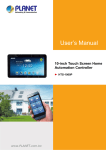
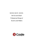
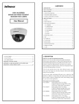
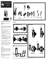
ATM Surveillance Camera
www.devieweurope.com
ATM Surveillance Camera Parts and Descriptions
User Manual
OSD Control Connector
Camera Lead Connector
OSD
Control Board
Short
Bracket
12VDC
*2 Knurling Knobs
Video Output
*4 Black Screws
Video Output
Camera Lead Connector
ATM
Surveillance Camera
*4 Silver Shoulder Screws
*1 Top Thumb Screw
24VAC/12VDC
Dual
Power Board
OSD
Control Board Cable
Long
Bracket
Extended
Arms
Screw Accessories
* Supplied with Dual Power model only
** 12VDC only model cannot connect to dual power board
700TVL High Resolution
Wire-ended Power
Adaptor Lead
Camera Lead
Connector
* Supplied with 12VDC model only
** 12VDC: connect directly to camera
V531-KA005-S00
Camera Installation and Connection
VER.06/2015
Installation
Choose an appropriate bracket from the two included
(Short or Long).
Installation
1 Remove the bracket from the camera
4
Bracket Adjustments
To change the bracket, remove the screws on each side of the
camera, remove the current installed bracket and then replace it
with a new version. Reinstall the attaching screws to secure the
bracket to the camera.
For specific locations, there are two extended arms which will
allow the camera to be positioned forward.
1. Remove the bracket by loosening the securing screws and
axis screws on both sides.
2. Place the two extended arms and secure the supplied axis
screws to the camera. Then set the positioning screws back
onto the camera.
Note: slightly tighten the axis screw and make sure the
extended arms are still rotatable.
3. Use the axis screws to install the bracket onto the extended
arms and then secure the positioning screws. Adjust the
position required and tighten the positioning screws so as to
fix the camera to the desired view angle.
2 Set up the extended arms
Short Bracket
Long Bracket
Note: Some installations require the bracket to be installed in
the ATM machine before attaching to the camera.
In the accessory bag you have securing screws or thumb knobs
that can be used to secure the camera. Choose which works
best for the installation. Once the camera is mounted and
positioned, secure the camera by tightening screws.
3 Secure the bracket and the extended arms onto the camera
Connection
Dual Voltage Version
Mount dual power board in desired location then attach the
camera lead. Next use the wire ended barrel plug to attach the
appropriate power source and plug into the mating connector
coming off the dual power board. Attach video cable and
installation is complete.
12VDC Version
Attach the camera lead then use the wire ended barrel plug to
attach the appropriate power source and plug into the mating
connector in the wire harness. Attach video cable and
installation is complete.
Make sure power is off before any connection is made.
Short Bracket
with Extended Arms
Note: There are multiple mounting positions on the extended arms which provide flexible mountings to different ATM machines.
Long Bracket
with Extended Arms
The OSD Control Board and
Programming
Control Menu Map
Menu Description
Press the [ENTER] key on the control board for three seconds to view the menu.
SETUP MENU
PAGE1
SCENE SELECT
Connect the OSD Control Board Cable to the
OSD Control Board (see image below)
FULL AUTO
INDOOR
OUTDOOR
BACKLIGHT
ITS
CUSTOM
SHUTTER /
AGC
AUTO
MANUAL
FIX
ATW(*1)
WHITE BAL
PUSH
USER1
USER2
MANUAL
PUSH LOCK
OFF
HLC
BLC(*2)
OFF
ATR-EX
HLC/BLC
OSD
Control Board
OSD
Control Board Cable
WDR/
ATR-EX(*3)
LEVEL
DAY
NIGHT
AUTO
Connect the OSD Control Board to the
Camera (see image below)
IR OPTIMZER
OFF
ON
001 ~ 250
6.0DB ~ 44.8DB
AUTO / OFF
256FLD ~ 1/10000
6.0DB ~ 44.8DB
256FLD ~ 1/10000
6.0DB ~ 44.8DB
000 ~ 255
001∼255
001∼255
INDOOR / SUNNY / SHADE / AUTO
RGAIN
BGAIN
RGAIN
BGAIN
LEVEL
000 ~ 255
000 ~ 255
000 ~ 255
000 ~ 255
00 ~ 63
CONTRAST
CLEAR FACE
CONTRAST
CLEAR FACE
0~6
LOW / MID / HIGH(*4)
LOW / MID / HIGH / OFF
LOW /MID / HIGH
OFF / LOW / MID / HIGH
MODE
AUTO
CENTER
﹍﹍﹍﹍﹍﹍
TOP
BOTTOM
LEFT
RIGHT
WEIGHT
Camera Lead Connector
ATM
Surveillance Camera
LEVEL
0-12
IR LED
OFF
FIX
DAY/NIGHT
COLOR NIGHT
IR SHADE COMP
With power applied to the camera and a video monitor
connected, press and hold the [ENTER] key for three
seconds to access the OSD top level menu. A map of
the setup menu options will be shown as the right of this
sheet presented.
LENS SHD COMP
To navigate through the menus, use the arrow keys on
the control board and use the [ENTER] key to select the
menu field desired.
ON
PICT ADJUST
PRIVACY MASK
UP
ENTER
MOTION DET
DOWN
SYS SETTING
EXIT
PATTERN
POSH
POSV
LEVEL
MODE
MODE
AUTO/OFF/ON
ANTI CR
DIS
EZOOM
RIGHT
OFF
ON
OFF
ON
OFF
AUTO
DEFOG(*5)
FLK LESS
LEFT
LEVEL
LEVEL MIN
LEVEL MAX
OSD Control Board with Cable
OFF
ON
COLOR GAIN
OFF
ON
PATTERN
POSH
POSV
LEVEL
SET1 / SET2 / SET3
000 ~ 959
000~490
LOW / MID / HIGH
GAIN CNTL
SHUTTER FIX
GAIN CNTL
SHUTTER FIX
BRIGHTNESS
CONTRAST
SHARPNESS
HUE
COLOR GAIN
ON/OFF
OFF
ON
MAG/PAN/TILT
AREA SEL
1~15
DISPLAY
OFF / ON
POSITION
WHITE / BLACK / RED /GREEN / BLUE /
COLOR
YELLOW / CYAN / MAGENTA
TRANSP
0.00 / 0.50 / 0.75 / 1.00
OFF / ON
MOSAIC
DETECT SENSE
OFF
INTERVAL
ON
BLOCK DISP
MASK AREA
MOTION AREA
AREA SEL
MODE
TOP
BOTTOM
LEFT
RIGHT
SYNC MODE
INT/LL(*6)
LENS
MANUAL
AUTO
TYPE
MODE
ADJUST
SPEED
FLIP
OFF/V/H/VH
LCD/CRT
PROTOCOL
COMMNUNICATION
ADDRESS
BAUDRATE
DATABIT
PARITY
STOPBIT
CAMERA ID
OFF
ON
POS
0~ 6
0~ 6
0~ 8
0~ 8
00~ 15
000 ~ 255
001 ~ 255
001 ~ 255
LOW / MID / HIGH
SET1 / SET2 / SET3
000 ~ 959
000~490
OFF / LOW / MID / HIGH
Brightness – Adjusts the brightness.
Contrast
– Adjusts the image contrast (light and shade differences).
Sharpness – Adjusts the sharpness.
– Adjusts the hue.
Hue
Color Gain – Adjust the color gain.
.
EZOOM – Adjust the digital zoom
– ON / OFF.
EZoom
MAG
– Magnification rate = ZOOM (0~255)
– Horizontal position settings.
PAN
– Vertical position settings.
TILT
DIS – Digital Image Stabilizer.
PRIVACY MASK – The mask function hides one or more areas which the user does not want
AREA SEL
DISPLAY
POSITION
COLOR
TRANSP
MOSAIC
MOTION DET
to be displayed on the screen.
– Select mask area (1-15).
– Mask to ON or OFF.
– Privacy regional choice
– Sets the color blend: RED/ GREEN/ BLUE/ YELLOW/ CYAN/ MAGENTA/
WHITE/ BLACK
– Sets the brightness blend ratio: 0%, /50%/75%/100%
– Open or close the mosaic function
– By using the motion detection function, it is possible to create surveillance
cameras which are capable of detecting moving objects.
DETECT SENSE – Select mask area (1-15).
INTERVAL – Sets the MD detection interval. Subjects are detected when an interval
exceeding the set number of fields has elapsed from the previous motion
detection.
BLOCK DISP – Motion detection result frame display selection.
Outputs the results of the motion detected in each block.
MASK AREA – MD (Motion Detection) setting menu, for setting the no-detection area.
MONITOR AREA – Sets the position of the monitoring frames in pixel or line increments.
SYS SETTING
SYNC MODE – External synchronization is a function with synchronization of the phase
between an output video signal and an external reference signal. Use line
lock mode to minimize color rolling.
LENS – Set the lens type.
FLIP – Select digital Flip / Rotate state Off / V(Top / bottom reversal) / H(Left / right reversal)
/ HV(Rotation by 180 degrees)
line increments.
CAMERA ID – Sets the camera ID to ON or OFF.
EXIT-MENU
SAVE
NOT SAVE
CANCEL
BACK
RETURN
LANGUAGE
VERSION
– Save the settings (settings are saved).
– Exit menu without saving.
– Changes (restore settings to those selected when the menu was displayed).
– Return to previous menu.
– Return to page on the hierarchical level immediately before.
– LANGUAGE select between: English, Chinese Spanish, Russian, Portuguese,
German, French, Japanese.
– Version Display
MAINTENANCE – Equipment maintenance
W.PIX MASK – W.PIX Repair set
CAMERA RESET – Reset the camera
IMPORTANT:
When any changes made to the camera configuration, use
the “SAVE SETTINGS” option in the “SAVE/RESTORE”
menu to save. Otherwise any changes made will be lost
when the camera is next reset or has its power cycled.
EXIT
SAVE
NOT SAVE
CANCEL
BACK
MANUAL
AUTO
RUN
BACK
DATA CLEAR
976(H) x 582(V)
60Hz
50Hz
700 TVL
0.3Lux(F1.2,50IRE,AGC ON)
Minimum Illumination
S/N Ratio
50dB (100 IRE, F1.2)
Composite (75 Ω BNC unbalanced connector)
Video Output
Input Terminal
DC Jack with fly lead attached
12 VDC ±10%
Power Source
12 VDC ±10% / 24 VAC ±20%
Power Consumption
2.2W Max.
Operating Temperature
-10°C ~ +50°C
Storage Temperature
-20°C ~ +60°C
Functional Specifications
Sense Up
ON / OFF
AES
Shutter Speed
MES
NTSC: 1/60 ~ 1/100000
PAL: 1/50 ~ 1/100000
1/50 (1/60), 1/120 (1/100), 1/250, 1/500, 1/1K, 1/2K, 1/4K, 1/10K
Wide Dynamic Range (WDR)
OFF/ATR-EX/WDR
High-Light Compensation (HLC)
ON/OFF
Backlight Compensation (BLC)
Full Range
AGC Gain Control
44.8 dB
Day/Night
SDN(AUTO ,COLOR ,NIGHT)
White Balance Control
ATW / Manual / Push / Push Lock / USER1,2
Auto White Balance Range
Indoor:1800K~10500K Outdoor:6500K~10500K
Mirror
OFF/V-FLIP/H-FLIP/HV-FLIP
Defog
ON/OFF
Sync System
INT /LL
Motion Detection
4 Areas
Privacy Zone
Up to 15 Masks
Digital Noise Reduction
3D DNR
Digital Zoom
255X Max
DIS
ON/OFF
Lens Specifications
Focal Length
2.8mm
F1.8
F-No.
Iris Range
2.5mm
F2.5
Fixed Range
Diagonal
Angle Of View : Horizontal
Vertical
128.0º
142.7º
98.0º
113.4°
81.5º
85.9°
Regulatory Compliance
Emissions: - CE:
--EN55022
--EN55011
- FCC:
--47 CFR Part15 Subpart B
--ANSI C63.4
--ICES-003
Immunity: - CE:
--EN55024
--EN50130-4
FCC COMPLIANCE:
This equipment complies with Part 15 of the FCC rules for intentional radiators and
Class B digital devices when installed and used in accordance with the instruction
manual. Following these rules provides reasonable protection against harmful
interference from equipment operated in a commercial area. This equipment should
not be installed in a residential area as it can radiate radio frequency energy that could
interfere with radio communications, a situation the user would have to fix at their own
expense.
ENGLISH/中文/ESPANOL/PORTUGUES/PYCCKNN/FRANCAIS/DEUTSCH/日本語
W.PIX MASK
CAMERA RESET
976(H) x 494(V)
Resolution
particular scene, so it allows average shooting in any situation.
– This mode is specialized to indoor scenes, such as indoor shop surveillance.
It allows natural shooting with high contrast.
OUTDOOR – This mode is specialized to outdoor scenes, Such as outdoor plaza surveillance.
It allows natural shooting with high contrast.
BACKLIGHT. – This mode is specialized to scenes that mix indoor and outdoor conditions,
such as entranceway surveillance.
– Monitoring and optimizing model of road.
ITS
PAGE2
LANGUAGE
VERSION
MAINTENANCE
Effective Picture
INDOOR
LCD / CRT
– Set the monitor type LCD or CRT.
COMMUNICATION (OPTION) – Sets the position of the monitoring frames in pixel or
1~4
NTSC
PAL
Sony 1/3" Super HAD-II Wide Dynamic
Scanning Frequency
image quality to suit the image output device used.
ON/OFF
BURST
BURST
ON/OFF
CNTL SIGNAL
INT/EXT1/EXT2
DELAY CNT
DAY->NIGHT
NIGHT->DAY
IR AREA
OSD Control Connector
adjusted manually
TV System
Image Sensor
FULL AUTO – This mode supports various shooting scenes. It is not specialized to any
PICT ADJUST – This Camera system provide functions that enable users to easily adjust the
000 ~ 255
CLIP LEVEL
WDR
DNR
DAY/NIGHT
AE LEVEL
AGC MAX
SENS UP
SHUTTER
AGC MAX
SHUTTER
AGC MAX
SPEED
DELAY CNT
ATW FRAME
ENVIRONMENT
SCENE SELECT – The six modes can be selected.
– This mode turns off the auto scene recognition. All functions canbe set and
CUSTOM
General Specifications
REGISTRATION
REG.POINT
CURSOR COLOR
BLINK
REG.NUMBER
CISPR 22 WARNING:
This can not be changed except CUSTOM mode.
This is a Class B product. In a domestic environment this product may cause radio
interference in which case the user may be required to take adequate measures.
POWER SUPPLY REQUIREMENTS:
For use with listed Audio/Video Product and only connected to 15W or less power supply.
Power supply should be a NEC Class 2 / LPS Supply.
EQUIPMENT MODIFICATION CAUTION:
Any equipment changes or modifications not expressly approved by the seller could cause
a hazardous condition and invalidate FCC compliance, thus voiding the users authority to
operate the equipment.