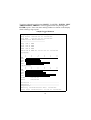
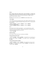
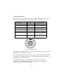
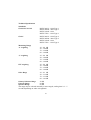
1
Thank you for buying a Castle product, I am sure you will find both the goods and the service to be of the highest quality but if not, then please feel free to write to me personally and I will ensure that your needs are dealt with immediately. This manual is designed to show you the operation of the goods you have purchased and a very brief insight into acoustics itself. If you would like to become a competent person in the eyes of the law, then you may like to know more about our Competent persons training course for the Noise at Work Regulations. It is my intention for Castle Group Ltd to provide a complete range of Noise and Vibration products and Services of the highest standard. If you would like to know more about any of our other products and services then please complete the reply paid card in this manual and return it to us for prompt action or telephone on +44(0)1723 584250. Simon Bull Sales and Marketing Director Precautions Operate the unit only as described in this manual. • The Professional range are precision Sound Level Meters. Protect them from shocks and vibrations. Take special care not to touch the microphone diaphragm. The diaphragm is a very thin metal film, which can easily be damaged. • Use only the microphone/preamplifier assembly supplied with your instrument. • Ambient conditions for operation of the unit are as follows : temperature range -10oC to +50oC, relative humidity 30 to 90%. • Protect the unit from water, dust, extreme temperatures, humidity, and direct sunlight during storage and use. Also keep the unit away from air with high salt or sulphur content, gases, and stored chemicals. • Always turn the unit off after use. Remove the batteries from the unit if it is not to be used for a long time (a week or more). When disconnecting cables, always grasp the plug and do not pull the cable. • Clean the unit only by wiping it with a soft, dry cloth or, when necessary, with a cloth lightly moistened with water. Do not use any solvents, cleaning alcohol or chemical cleaning agents. • Take care that no conductive objects such as wire, metal scraps, conductive plastics etc. can get into the unit. • Do not try to disassemble or alter the unit, otherwise type certification will become invalid. In case of an apparent malfunction, do not attempt any repairs. Note the condition of the unit clearly and contact the supplier or Castle Group direct. To ensure continued precision, have the unit checked and serviced at regular intervals. • When using the unit for commercial purposes or for certification, official certification is required at least once a year. Contact the supplier or an authorised Castle service agent. CONTENTS TITLE PAGE NO Instrument Introduction and Features 6 Battery Installation 9 Attaching the Microphone 10 Switching On and Off 11 Backlighting 11 Locating and Activating Functions 11 Using the Manual 13 Calibration 13 Setting the Exchange Rate 13 Setting the Criterion 13 Metering 14 Setting the Print Configuration 15 Logging 16 Locking and Unlocking the Instrument 18 Communicating with the PC 18 Taking an Octave Band Snapshot 19 CONTENTS TITLE PAGE NO Hearing Protection Devices – HPD 20 Printing 21 Status 25 Auto-Range 25 Save 25 Defaults Settings 25 Setting the Real Time Clock 25 Setting the Real Time Calendar 25 Technical Information 26 Technical Specification 27 Available Accessories 34 Warranty and After Sales Service 35 Instrument Introduction and Features This manual contains complete operating instructions for models GA120, 121, 122, 123 and 221. Read it carefully and you will quickly become familiar with your instrument. If you have problems with the operation of any model, please call 01723 584250. The professional range of instruments are designed for two specific areas, Industrial and Environmental noise measurement. The Industrial range comprises the GA121 which is a Type 1 Precision Integrating Sound Level Meter. The ideal instrument for industrial and environmental applications featuring the unique automatic octave snapshot and HPD library. In addition to the GA121 there is the GA221 Type 2 Integrating Octave Sound Level Meter. This unit is manufactured to the less demanding Type 2 standards for economy, but still retaining all the features of the GA121 except the back-light function of the LCD. The following features are common to both the GA121 and GA221 unless stated otherwise. • Unique Hearing Protection Data file • Data Logging • Alpha Numeric Print Out • Automatic Octave Scan • RS232 interface • Auto Ranging • Real Time & Date • Auto Calibration • Back Lit LCD (GA121 only) • Long Battery Life 6 The Environmental range comprises the GA120, GA122 and the GA123 which are all Type 1 Precision Integrating Sound Level Meters. The ideal instruments for environmental applications. The GA123 is the top of the range model and in addition to its comprehensive environmental capabilities it features the unique Octave Band Mode facilities. The first mode, an Automatic Snapshot plot determines noise levels in octave bands for storage in memory, for computer down loading or direct print out. The second mode enables the same data to be recorded Manually and either set of results may be processed in the third HPD (Hearing Protection Data) mode enabling the values to be compared to the attenuation capabilities of up to 500 Hearing Protectors in the instrument’s own library making the daunting task of product selection as simple as possible. The GA123 also has 10 assignable event markers. The GA122 has all the facilities found on the GA123 with exception of the Octave Band Modes and offers an unbeatable combination of sophisticated technology with remarkable value for money. The GA120 is the most basic instrument in the range, but it still offers every facility for simple, accurate environmental sound measurement and a level of sophistication not offered by any other manufacture at this price level. The following features are common to the GA120, GA122 and GA123 unless stated otherwise. • Back lit LCD • Real Time and Date • Auto Ranging • Event Markers • Long Battery Life • Video Style Timer • ‘A’, ‘C’, and Lin • Hearing Protection Selection • RS232 Interface • Dat Recorder Compatible • Octave Band Analysis (GA123 only) 7 FEATURES GA221 GA120 GA121 GA122 GA123 40 40 40 40 40 50 50 50 Peak logged value Min RMS & Event time SEL Octave Band Snapshot DOSE Projected Dose Dose/Hour Start/Stop programmable 9 Event markers Set Log periods Custom Log periods Memories: Snapshot Logs L10, L90 Industrial mode logging Environmental mode Logging One Touch Logging Octave snapshot print Backlighting Hearing Protector attenuation 8 Battery Installation Use 3 high-capacity 9V batteries, Type 6LR61. The instrument will function with one or two batteries, but with a reduced running time. Do not use rechargeable batteries. When BATTERY LOW appears in the display window, replace all batteries as soon as possible, otherwise the instrument's specification cannot be guaranteed. Seria l No . 012345 Seria l No . 012345 Re m o v e Co v e r t o c ha ng e Ba tt e rie s C a stle Assoc ia tes Salt er R o ad ,ite Sc d arb or oug h, Lim Englan dFa. x: 0723 583728 Tel: ( 0723) 584250 Release the spring catch and remove the battery compartment cover Press clip, remove cover, attach batteries to connector, replace cover firmly and close clip. NOTE: A built-in lithium battery with a life of approximately 3 years provides back-up for the instrument's real-time clock and calendar and data storage. A new battery will be fitted when the instrument is returned for its annual re-calibration. 9 Attaching the Microphone Align the red dots on microphone and instrument, grip the microphone's collar and push firmly. To remove the microphone, reverse this process. Do not twist the microphone. Pull the microphone assemb away from the instrument, along it's axis. Grip the knurled collar CASTLE CASTLE 10 Switching On and Off Press and hold the POWER button until the display illuminates. Wait a few seconds while the instrument runs through its start-up sequence. When READY appears in the display window, the instrument is ready for use. To switch off, press and hold the POWER button until the display goes blank. Backlighting Press the LIGHT key and the display will be backlit for approximately 10 seconds. Locating and Activating Functions Castle instruments operate with a menu system. To select from the menu, press the left or right arrow buttons from the central cluster until two arrows in the display - the cursor - point to your desired function. Then press ENTER E.g. Press METER READY:V2.0 ←→ >LOG<SETUP LOCK The cursor points to LOG. METER: ←→ >LOG<SPL Leq Press the right arrow twice. METER: ←→ LOG SPL>Leq < The cursor points to Leq. Press ENTER to select Leq. This symbol ←→ in the top right hand corner of the display shows that there are more functions in that menu than will fit onto the screen. Pressing the left or right arrow buttons will scroll the screen in either direction one function at a time, until the one you are seeking moves into view. 11 Eg. READY:V2.0 ←→ >LOG<SETUP LOCK Press the up arrow. Press METER. METER: ←→ >LOG<SPL Leq The cursor points to SPL, press the right arrow twice. METER: ←→ LOG SPL>Leq< Press the left arrow twice, the cursor points to TIME. METER: >TIME< Press the left arrow until the cursor points to Leq. METER: ←→ LOG SPL>Leq< ←→ Pressing the ENTER key has two functions. One is to activate a procedure, the other is to move the operating procedure down onto the next menu level. To move back onto previous menu levels, press the up arrow. READY:V2.0 ←→ >LOG<SETUP LOCK Press the up arrow. Press METER. Then press the right arrow METER: ←→ LOG>SPL<Leq Press ENTER, the SPL reading is shown. SPL: 56.8 dBA S 30 Press the up arrow and the previous menu is restored. 80 METER: ←→ LOG>SPL<Leq There are further keys which allow access to certain functions with one touch. Their use and the use of the numeric keys, will be discussed in the relevant parts of this manual. 12 Using the Manual In the course of this manual, these symbols >< mean move the left and right arrows to move the cursor. E.g. >PEAK< means move the cursor until it points to PEAK. A named key written in BOLD means press that key. E.g. ENTER means press the ENTER key. Calibration The instrument should always be calibrated before use, a Castle GA607 Calibrator is recommended. The instrument's in-built default calibration level is 94dB. Switch on the instrument and attach a suitable calibrator to the microphone. CAL and wait a few seconds for an SPL figure to appear. Then ENTER. The instrument is now calibrated. If a source other than 94dB is used: once CAL is in operation, use the LEFT ARROW/RIGHT ARROW to set a new calibration level, then proceed as above. Setting the Exchange Rate >SETUP<, ENTER, >EXCH<, ENTER. LEFT ARROW/RIGHT ARROW to select exchange rate, then ENTER to confirm. 3dB - European Standard 5dB - American Standard Setting the Criterion >SETUP<, ENTER, >CRIT<, ENTER. LEFT ARROW/RIGHT ARROW to select criterion, then ENTER to confirm. 13 Metering Brief description of terms under METER. SPL - gives accurate values of 'A' , 'C' or Linear weighted sound pressure level. Leq - provides the facility for measuring Leq, LAeq or LCeq. The elapsed time shows the continuous period of time for which the Leq has been accumulating. Lmax - the maximum rms sound pressure level. Shows the real time when Lmax was last updated and the Event time. Lmin - the minimum rms sound pressure level. Shows the real time when Lmin was last updated and the Event time. Peak - the peak is continuously captured and is the measure of true Peak. The measurement is a linear weighted sound pressure level and is only valid when the peak exceeds 80 dB's. The event time shows the real time at which the Peak was last updated. PrLep,d - a projection of the Lep,d which is a variable dependent on the A weighted sound pressure level and the duration of exposure. It is therefore only valid when 'A' weighted. RMS - a flag which is only set when the 'A' weighted, SLOW response SPL exceeds 115 dBA (rms). Time - the elapsed time, which is the period of time for which the instrument has been switched on, and the real time and date. METER then > < to SPL, Leq, Lmax, Lmin, PEAK, PrLep,d, RMS, TIME. ENTER LEFT ARROW to set Filter Weighting: A, Linear or C. RIGHT ARROW to set Time Weighting: Slow, Fast, Impulse. RANGE to set range: 30, 50, 70, 90. N.B. Once a function on this menu level has been selected, ENTER will bring other functions up on screen: SPL, Leq, Lmin, Lmax, PrLepd, PEAK, RMS, TIME. 14 Setting the Print Configuration It is possible to set your Sound Level Meter to print only the parameters of a log that you want to print, it is also possible to set your SLM to print all the logs in memory fully or just the summary data from all the logs. >SETUP<, ENTER, >PRINT<, ENTER access the print setup menu. Set printout to Summary >ALL<, ENTER, >SUMMARIES<, ENTER - only summary data of locations will be printed (when PRINT,>ALL<, ENTER is selected). Set printout to ALL >ALL<, ENTER, >SUMMARIES<, ENTER - all data selected for loctaions will be printed (when PRINT,>ALL<, ENTER is selected). Setting IND printout parameters >IND<, ENTER - brings up menu of parameters of Industrial log which can be set (see print options). Setting ENV printout parameters >ENV<, ENTER - brings up menu of parameters of Environmental log which can be set (see print options). Print Options select the parameter you wish to setup e.g. >LEQ<, ENTER, Set selection to graphic printout >GRAPH<, ENTER - selects bar graph printout for data. Set selection to text printout >TEXT<, ENTER - selects text printout for data Set selection to no printout >OFF<, ENTER - disables printout for data. 15 Logging Logging is performed against a choice of two sets of measurement variables - Industrial and Environmental. Industrial variables are: SPL, Leq, Dose, Projected Dose, Dose per Hour, Lmax and Peak. Environmental variables are: SPL, Leq, Lmax, Lmin, SEL, L10, L50 or NNO which is the Night time Noise Offence, and L90. Both modes also indicate elapsed TIME and INFO - a reminder of logging mode, time intervals, numbered locations and the number of logged intervals which have been recorded. Starting a log > LOG <, ENTER > MANUAL <, ENTER > IND < or >ENV < ENTER > < to select time interval: 1 minute, 10 minutes, 15 minutes, 1 hour or >USER< to define a different time interval. ENTER. Logging is now underway. To see the logging data, >VIEW< to bring up a list of variables then > < to select. ENTER. Whilst viewing one variable, ENTER will bring the next on screen. Press up key to return to upper level. Ending a log Have VIEW/END/EVENT/LOCK on screen. >END<, ENTER, >END< , ENTER. To pause logging, have VIEW/END/EVENT/LOCK on screen. >END<, ENTER, >PAUSE<, ENTER. To resume or end logging, > END< ENTER, > CONTINUE < or >END < Alternatively use the key, pressing toggles the logging status. 16 To mark events, have VIEW/END/EVENT/LOCK on screen. > EVENT <, ENTER. Use numeric keys to add a number between 1 and 9. To lock the instrument, have VIEW/END/EVENT/LOCK on screen. ENTER, then ENTER to lock. To unlock the instrument, RESET, ENTER, RESET. Clearing logging data > LOG <, ENTER, >CLEAR<, ENTER, >LAST< or >ALL<, ENTER, then RESET to confirm. If >CLEAR< is selected in error, press up arrow key to return to menu. Using the timer > LOG <, ENTER, >TIMER<, ENTER, >IND< or >ENV< ENTER. > < to select time interval, ENTER. Use numeric keys to select start time in hours, minutes, month and day then select end time in hours, minutes, month and day. ENTER after each selection. The timer is now set. RESET to clear. The instrument will turn off if the start time is more than 32 minutes away. After 32 minutes, the instrument will come on for approximately 10 seconds to check the start time. It will continue to do this until the start time is within 32 minutes. When the start time is less than 32 minutes away the instrument will turn on in readiness to start its log. To halt the timer before the start time is reached, POWER, RESET and the instrument will clear. One Touch Logging OTL begins a log with the same parameters of the previous logging mode i.e. Industrial or Environmental - using whichever time intervals were last used. If the previous log used the TIMER, new start and end parameters will have to be keyed in. Positioning of user When you are taking measurements always ensure that you hold the meter, with the microphone attached, away from your body to avoid any reflections from your body. 17 Locking and Unlocking the Instrument Locking the instrument prevents unwanted keypresses from altering settings if the instrument is logging in an area where this is likely. A specific key sequence unlocks the instrument. To lock the instrument >LOCK<, ENTER, ENTER To unlock the instrument RESET, ENTER, RESET Communicating with the PC To use this facility a licensed copy of dBdata for Windows must have been purchased. First ensure that data has been stored on the instrument either in the form of logged data or octave snapshots. Then connect the instrument to the PC with the appropriate 2 meter length Castle ZL1101-2 cable, not to be confused with the Castle ZL1082-01 1 meter printer cable. To allow the instrument to communicate with the PC, >LOG<, ENTER, LEFT ARROW, >COMPUTER<, ENTER. For more detailed information on dBdata refer to your user manual. 18 Taking an Octave Band Snapshot This function involves taking and logging a band pressure level in each octave to determine the relative frequency content of a particular sound field. OCTAVE, >SNAPSHOT<, ENTER, >LIN<, >A< or >C<, ENTER, >AUTO<, ENTER. The snapshot process takes approximately 1 minute 45 seconds. On completion of the process, all the instruments except the GA221 ask if you wish to log or print the data. >YES<, >NO< or >PRINT<, ENTER. N.B. For PRINT command, see separate heading. If >MANUAL< is entered instead of >AUTO<, band pressure levels in each octave must be allowed to settle, at the user's discretion, and manually accepted using ENTER before moving onto the next band. To view snapshot data: OCTAVE, >VIEW<, ENTER. LEFT ARROW/ RIGHT ARROW to select an octave location then ENTER to view the frequencies in sequence. Once data for the final frequency has been shown, the next ENTER will show the highest reading from all frequencies. The GA121, can store 40 numbered snapshots, the 123 can store 50. To select a particular snapshot location: >OCTAVE<, ENTER, >VIEW<, ENTER, then LEFT ARROW/RIGHT ARROW to choose the required location, ENTER. ENTER again to view the frequencies in order. To clear snapshots: >OCTAVE<, ENTER, >CLEAR<, ENTER, >LAST< or >ALL<, ENTER, then RESET to confirm. If >CLEAR< is selected in error, UP ARROW will return the user to the menu. 19 Hearing Protection Devices – HPD This feature produces hearing protection analysis based on an Octave Band Snapshot. Instruments with this feature contain an extensive library of specifications for many popular makes and models of HPD's. Specification of models not featured can be entered using the manufacturer's data. First take and log an Octave Snapshot within the sound field against which protection is required (see previous section). If the snapshot was taken on a filter weighting other than that of ‘A’, i.e. LIN or ‘C’ the instrument calculates the approximate ‘A’ weighted levels in each octave. >HPD<, ENTER, >SELECT<, ENTER. > < to select manufacturers, ENTER. > < to select models, ENTER. To define a Hearing Protection Specification for a device which is not in the instrument's memory: >HPD<, ENTER, >DEFINE<, ENTER. Do the following actions for each octave band frequency: > < to select frequency, ENTER, key in the Linear attenuation x 10 dB for the chosen octave band according to the manufacturer's data, ENTER. e.g. if the attenuation is quoted as 15.6dB at 1KHz then enter 156 when prompted, for the desired attenuation at 1KHz. This information will now appear on the list of manufacturers (see above) under >USER<. 20 Printing Instruments should be connected to a GA505 digital printer using a ZL1082-01 printer cable. PRINT, >SUMMARY<, ENTER produces this printout. Sample Summary Printout Summary Printout ---------------Time Date :00:55.51 :26/09/94 Weighting is A Slow Elapsed Time:02:34.04 Leq : Lmin: Lmax: Peak: 70.0 54.3 90.8 97.9 dB dB At 22:55.02 dB At 22:55.40 dB At 22:55.40 Projected Lepd: 70.0 dB Overload Flag not set. 115 dBA RMS flag not exceeded. Location :............................ Operator :............................ Signature:............................ Factory recalibration due: 01/09/98 Last user calibration: 20:16 on 25/06/98 21 To print an octave snapshot: PRINT, >SNAPSHOT<, ENTER. LEFT ARROW/RIGHT ARROW to select snapshot for printing, then ENTER to print. Note time, date and snapshot number are shown on the display when selecting a snapshot to print. Sample Octave Band Snapshot Octave Band Snapshot -------------------Weighting is Lin Slow Snapshot type: Manual Band: ¦ BPL (dB) ------¦--------31 Hz¦ 65.7 63 Hz¦ 50.9 125 Hz¦ 52.5 250 Hz¦ 56.2 500 Hz¦ 54.3 1 KHz¦ 48.8 2 KHz¦ 83.7 4 Khz¦ 52.3 8 KHz¦ 40.9 16 Khz¦ 29.6 Time Date :22:36.33 :25/09/94 Location :............................ Operator :............................ Signature:.........................… Factory recalibration due: 15/04/95. 22 To print a selected hearing protection device performance within a measured sound field: first take an Octave Snapshot. Then OCTAVE, >HPD<, ENTER, >SELECT<, ENTER, > < to the required manufacturer, ENTER, > < to the required model, PRINT. Sample HPD Printout H.P.D. Printout --------------Manufacturer: BILSOM Model:BLUE Time Date :10:37.30 :27/09/94 Snapshot time Snapshot Date :22.36.33 :25/09/94 All measurements are A weighted. BAND 63 Hz 125 Hz 2 0 4 0 6 0 8 0 1 0 0 1 2 0 1 4 0 250 Hz 500 Hz 1 KHz 2 KHz 4 KHz 8 KHz Location :............................ Operator :............................ Signature:............................ Factory recalibration due: 16/09/95. Last user calibration: 21:16 on 25/09/94 23 1 6 0 To print a selected logged location: PRINT, >LOGGED<, ENTER. LEFT ARROW/RIGHT ARROW to select logged location for printing, then ENTER to print. Note time, date and log number are shown on the display when selecting a log to print. Sample Logged Printout Logging mode:Environmental, A Slow. Log Start :23:29.55 on 25/09/94. Log End :23:32.55 on 25/09/94. Cumulative Measurements: -----------------------Leq :58.1 dBA L10 :56.0 dBA L50 :50.4 dBA L90 :46.9 dBA Lmin:38.8 dBA At 23:31.05 on 25/09/94 Leq Tim e H istory -----------4 0 5 0 6 0 7 0 8 0 L90,L10 Tim e H istory -----------------3 4 0 0 TIME 23:29 5 0 6 0 7 0 8 0 3 0 TIME 23:29 23:30 23:31 23:32 23:30 23:31 23:32 Time Date :12:19.51 :26/09/94 Location :............................ Operator :............................ Signature:............................ Factory recalibration due: 15/04/95. Last user calibration: 21:16 on 25/09/94. 24 Status This function shows the current status of the instrument. It shows the battery strength whether the instrument is paused or running and whether an overload has occurred. Three bars indicate full battery strength, replace batteries when one bar is shown. STATUS shows the status screen. STATUS exits the status screen. Auto–Range Auto-ranging selects the optimum range for the ambient sound field and may not be suitable for rapidly fluctuating sound pressure levels, or short period measurements. >SETUP<, ENTER, >RANGE<, ENTER, >AUTO<, ENTER. To de-select Auto-ranging: >SETUP<, ENTER, >RANGE<, ENTER, >AUTO<, ENTER. Save This function saves all meter parameters – e.g. Leq, Lmin, Lmax etc and waits for the unit to be turned off. When the instrument is turned back on it will resume measuring from the save point. >SAVE<, ENTER Default Settings This function returns the meter to its factory set defaults. Setting the Real Time Clock >SETUP<, ENTER. >TIME<, ENTER. Use numeric keys to type hours in 24 hour clock method. ENTER. Use numeric keys to type minutes. ENTER. Setting the Real Time Calendar >SETUP<, ENTER, >DATE<, ENTER. Use numeric keys to type in year. ENTER. Use numeric keys to type in month. ENTER. Use numeric keys to type in date. ENTER. 25 Technical Information The instrument is equipped with a seven pin LEMO socket which provides an RS-232 communication port, an AC output, and a power input. PIN NUMBER SIGNAL DESCRIPTION 1 GND Signal Reference 2 Rx RS-232 Data Input 3 Tx RS-232 Data Output 4 NOT USED 5 CTS RS-232 Handshaking Line 6 BAT Aux power input (6V-9VDC) 7 AC AC output – 375mV rms at f.s.d. into 600 ohms 1 6 7 2 3 5 4 Seven Pin LEMO socket The RS-232 communication port will directly interface the Castle GA505 digital printer, via a ZL1082-01 cable. The AC output is a representation of the sound pressure level incident on the microphone. This output can be used, in conjunction with a tape recorder, to log information for FFT analysis. The BAT and GND inputs provide a direct connection to the battery terminals. An auxiliary power supply can be connected, via the LEMO socket, to provide extended running times. 26 Technical Specification Standards GA120/121/122/123 GA221 Measuring Range ‘A’ weighting BS EN 60651 : 1994 Type 1 BS EN 60804 : 2001 Type 1 BS EN 61260 : 1996 BS EN 7580 : 1992 Type 1 BS EN 60651 : 1994 Type 2 BS EN 60804 : 2001 Type 2 BS EN 61260 : 1996 BS EN 7580 : 1992 Type 2 30 – 80 dB 50 – 100 dB 70 – 120 dB 90 – 140 dB ‘C’ weighting 30 – 80 dB 50 – 100 dB 70 – 120 dB 90 – 140 dB LIN weighting 30 – 80 dB 50 – 100 dB 70 – 120 dB 90 – 140 dB Pulse Range 30 – 93 dB 50 – 113 dB 70 – 133 dB 90 – 143 dB Primary Indicator Range 50 dB Linearity Range 60 dB Dynamic Range 60 dB The range may be selected manually or auto-ranged, settling time is 3 – 5 seconds depending on order of magnitude. 27 Frequency weighting GA120/121/122/123 ‘A’, ‘C’ and Linear to BS EN 60651 Type 1 GA221 N.B ‘A’, ‘C’ and Linear to BS EN 60651 Type 2 The frequency range of this instrument is to type 2 standards. Outside of this range, precision is not assured. Data for the 16kHz range should therefore be used only as a general reference. Time weighting GA120/121/122/123 Slow, Fast and Impulse to BS EN 60651 Type 1 GA221 Slow, Fast and Impulse to BS EN 60651 Type 2 Detector Characteristics Dynamic Characteris- Time Constant Rise Time Decay Time Slow 1s 1s Fast 125 ms 125 ms Impulse 35 ms 1.5 ms True RMS and simultaneous PEAK (linear). Crest factor capability 13 dB at full scale deflection Signal to Noise ratio > 5 dB at bottom of scale EMC Performance Radiated emissions to EN 50 081-2 No significant emissions from the instrument 28 Display GA120/121/122/123 GA221 Microphone / Preamp GA120/121/122/123 Back-lit LCD: 2 x 16 character dot matrix Temperature compensated contrast LCD: 2 x 16 character dot matrix Temperature compensated contrast Pre-polarised ½” (12.7mm) Electret condenser Sensitivity -27 dB ± 1.5 dB re 1V/Pa Capacitance: 20 pF Impedance: 10 Gohm GA221 Pre-polarised ½” (12.7mm) Electret condenser Sensitivity -43 dB ± 2.5 dB re 1V/Pa Capacitance: 20 pF Impedance: 10 Gohm The electrical impedance substituted for the microphone for test purposes is 560 ohms Calibration Reference level Range Tolerances 94 dB @ 1kHz 70 – 120 dB Type 1 ± 0.7 dB, Type 2 ± 1.0 dB (carried out after warm up time) Acoustic reference level provided by GA601 or GA607 Temperature Effect Warm up time Operating range Warning Vibration Effect Humidity Effect Warning < 0.5 dB across operating range < 10 minutes -10°C to +50°C DO NOT subject the instrument to temperatures greater than 70°C or less than -20°C for any length of time. From 20Hz to 1kHz at 1ms-2 no noticeable effect < 0.5 dB from 30% RH to 90% RH The instrument is NOT water resistant. 29 Magnetic Field Effect No noticeable effect Body in Free Field Effect No noticeable effect Extension Cable Attenuation for 10m cable < 1 dB below 12kHz Windshield Attenuation < 0.2 dB Overload Positive overload warning when the input circuits saturate Time Battery backed Real Time clock and calendar Memory Battery backed 1 Mbit RAM, 512 Kbit ROM Communication Port RS-232 Output Socket AC Output 2400 baud, 8 bit, no parity, 2 stop bits Standard interface to GA505 digital printer Connector 375mV rms at fsd into 600ohm load Short circuit protected LEMO FGGOB307CLAD52Z Overall Dimensions Dimensions Weight 280mm x 80mm x 40mm (approx) 900g inc batteries Batteries Type Life 3 x 6LR61 PP3 (9V alkaline cells) 30 hours continuous use (approx) based upon comparative bench tests with other batteries Use of the back light will reduce the effective battery life 30 Default Settings Criterion Exchange rate Frequency weighting Time weighting Range 90 dB 3 dB ‘A’ weighted Slow Auto ranges on start up Reference direction of incidence Zero degrees about the axis of the microphone capsule Octave Band Filters Centre frequencies GA121/123 31.5Hz, 63Hz, 125Hz, 250Hz, 500Hz, 1kHz, 2kHz, 4kHz, 8kHz, 16kHz GA221 31.5Hz, 63Hz, 125Hz, 250Hz, 500Hz, 1kHz, 2kHz, 4kHz, 8kHz The octave band filters are implemented by a switched capacitor filter. Switched Capacitor Filter Theory The basic principle behind the switched capacitor filter is the fact that a simple circuit, based around a single capacitor, can be used to reproduce the characteristics of a resistor. 1 . 1 1 3 2 1 1 1 During time T1, the switch connects the input voltage across C1 which charges to V1. During T2, the switch is connected to the output and C1 discharges to V2. 31 The basic switched capacitor circuit can be included in a linear integrator to form a switched capacitor integrator. 3 1 1 2 3 + 2 1 - 1 1 1 The switched capacitor integrator forms the basic building block of the octave band switched capacitor filter. The centre frequency of each octave band filter is determined by the clock frequency. The switched capacitor octave band filter requires a clock frequency of approximately 54 times the centre frequency of the octave band selected. Octave Band Centre Frequency 31 Hz 63 Hz 125 Hz 250 Hz 500 Hz 1 kHz 2 kHz 4 kHz 8 kHz 16 kHz Clock Frequency 1.7 kHz 3.38 kHz 6.75 kHz 13.5 kHz 27.0 kHz 54.0 kHz 108 kHz 216 kHz 432 kHz 864 kHz Base-Ten The base-ten system was used to determine the octave band frequency ratio. G10 = 10 3/10 The centre frequencies are calculated using the following formula: fm = (G x/b) (fr) fm is the required centre frequency fr is the reference frequency of 1000 Hz x is an integer, positive, negative or zero b is one 32 Octave Reference Levels Level Range Input Signal Reference Attenuation 50 – 100 dB 94 dB for all octave bands is ± 0.3 dB 33 Available Accessories GA607 Dual Level Calibrator Class 1 GA505 Portable Digital Printer ZL1082-01 GA505 Printer Cable 1m ZL1090-01 Microphone Extension Cable 1m KA009 Kit Bag for SLM and Printer KA005 Shoulder Kit Bag for SLM KG205 Windshield for ½” Microphone KT102 Heavy Duty Tripod (up to 1.6m high) PSU2 Mains Power Supply for Professional Range CPGA503 GA505 Printer Paper (pack of 5 rolls) 6LR61 Battery Pack (pack of 10 batteries) KA011 Weatherproof Kit Assembly MW400 Weatherproof Microphone Housing Software Package PC005 dBdata4W Noise Windows based software (plus cable) 34 Warranty and After Sales Service Castle Group design and manufacture precision instruments, which if treated with reasonable care and attention should provide many years of trouble free service. In the event of a fault occurring, during the warranty period, the instrument should be returned to Castle Group Ltd, in its original packaging, or to an authorised agent. Please enclose a clear description of the fault or symptom. Details of the warranty cover are available from Castle Group Ltd or an authorised agent. All instruments are designed to meet rigid British and International Standards. An annual calibration is recommended to ensure that these high standards are maintained. This is particularly important for cases in which instrument readings are to be used in litigation or compliance work. For warranty and service return to: The Service Department Castle Group Ltd Salter Road Cayton Low Road Industrial Estate Scarborough North Yorkshire YO11 3UZ Telephone Fax UK: INT: UK: INT: (01723) 44 1723 (01723) 44 1723 584250 584250 583728 583728 Any misuse or unauthorised repairs will invalidate the warranty. Damage caused by faulty or leaking batteries is not covered by the warranty. 35 Notes H:\Research & Development\Manuals\Professional Range manual 36 HB/0121/014/A5 Issue C