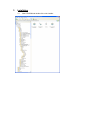
1
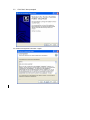
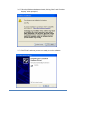
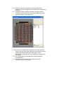
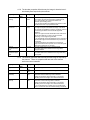
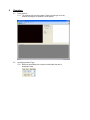
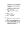
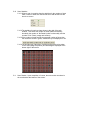
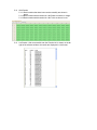
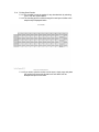
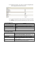
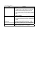
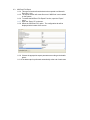
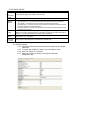
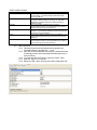
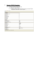
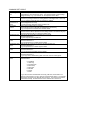
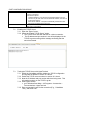
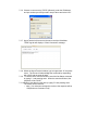
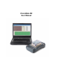
VisionMate SR User Manual 1 VisionMate SR Overview 1.1 Specifications Dimensions (W x D x H) Weight Power Supply 55 x 280 x 160 mm 2.17” x 11” x 6.3” Approx 0.8 kg (1.76 lbs) 110-240 V, 50-60 Hz Speed Decoding Capacity Approx 5-12 seconds per rack depending on PC performance. 1 up to 96 tubes. Supported Barcode Type Computer Requirements Connection Method Power Consumption Technology Any Thermo Scientific 2D Barcoded Storage Tube as well as virtually any other tube with high contrast 2D codes 1 GB RAM PC with Microsoft® Windows® 2000, Windows XP or higher (including Windows Vista®) with 2 free USB2 ports. Via supplied USB cable to USB2 interface. 12 W (operation) Colour CCD image sensor 1.2 Software 1.2.1 So after I’ve installed the software… what do I do next? Place your rack on the scanner Enable the racks you are using in the software by clicking the enable buttons, then hit scan. 1.2.2 What does the Software do? The VisionMate SR software allows you to scan a rack of Thermo Scientific 2D data matrix-coded tubes and save the results to output files in one simple operation. 1.2.3 How can I store my data? You can save data to Text file, CSV file, MS Excel file, COM Port, XML file, ODBC database and via a TCP/IP connection. The storage of data is designed to be very flexible and easy to configure. Data is exported as soon as a scan is complete without the need for user information. 1.2.4 What configuration changes do I need to make? None for decoding racks. The only configuration required is for export function which is typically a case of selecting what type of file to create and where you want output files to be stored. 1.2.5 Can I use my old software with a new VisionMate SR? No. The hardware is not compatible with older versions of Thermo software. 1.2.6 Can I run the new VisionMate SR on Windows Vista, or Windows 7? Yes. This software is compatible with both Windows Vista and Windows 7. 1.3 Hardware 1.3.1 Can I run a SmartScan Solo or VisionMate High Speed reader on the same computer as the VisionMate SR reader? Yes. But you only need to use the security key already included in the VisionMate reader (so the separate key for the Solo is not necessary). 1.3.2 Can I run two VisionMate SRs on the same computer? No 1.3.3 Can I run the VisionMate SR on a Mac? In some cases…..with the latest Mac models and utilizing the latest version of the Mac OS running Windows XP in a virtual machine this is possible. Older models and software or running straight off of the Mac OS is not possible. 1.3.4 Can I use a USB 1.X port to connect the VisionMate SR Scanner? No. The scanner requires a USB 2 port. Using a USB 1.X port will cause very slow scan speeds and could cause erratic performance and application errors. 1.3.5 Do I need to perform maintenance on my VisionMate SR scanner? No, apart from keeping the glass clean and dust-free, including ensuring the corners do not accumulate debris, there is no maintenance necessary. 1.3.6 Can I use an external USB hub to connect the scanner and dongle? Yes, this is normally fine if you use a good quality hub, but if you do begin to experience problems with image quality then the scanner should be connected directly to the PC USB port. 1.4 Speed 1.4.1 What affects the speed of my VisionMate SR scanner? The speed of the scanner is generally influenced by the computer hardware. Increasing memory and processor speed will often decrease scanning times. Additionally, using the intensive scan mode will decrease the scan cycle time, due to the increased amount of data being processed by the software. 1.4.2 How long does it take to scan a rack? The scanner will typically read a single rack in 5 to 12 seconds. 1.4.3 What affects decoding speed? The main factor which affects decoding speed is the processing performance of the PC. An unloaded PC which meets the recommended specification should scan a good rack of 96 tubes in seven to eight seconds. 1.5 Scanning Different Tube Types/Conditions: 1.5.1 How do I scan different rack sizes? Each rack has a separate rack size configuration box. Either use the drop-down menu to select a common rack size e.g. 96 or 48 tubes, or alternatively use the rows and columns options to set the correct rack configuration. Supported rack sizes are from 1x1 tubes up to 24x16 tubes. 1.5.2 How do I scan racks from different manufacturers? The scanner is configured to read all rack types on the same settings. 1.5.3 Which manufacturers’ tubes are supported? All tubes produced by Thermo Scientific are supported as well as most other manufacturers tubes. 1.5.4 Does this reader work with REMP tubes? No. We do not support or promote this product as being compatible with REMP’s type of 2D code. 1.5.5 Can the new VisionMate read Matrix 12 mL tubes? 2.0 mL or 5 mL Abgene tubes? Matrix Glass tubes? 14 x 14 codes? Nunc screw cap tubes? 14x14 and 12x12 codes in the same rack? Yes, yes, yes, yes, yes, yes! 1.5.6 Can the VisionMate SR read Matrix 384 tubes? No, Other Thermo Scientific readers are available if you need to read Matrix 384 tubes. 1.5.7 Can I scan very cold racks (from VPLN) on the VisionMate SR scanner? Yes. The scanner contains protection against internal condensation, though if the base of the tubes is highly frosted over we would recommend wiping the base of the tubes with a pre-saturated isopropyl wipe. 2 Parts 2.1 Included in this packaging you should find the following: 1) 2) 3) 4) 5) 6) 2.2 VisionMate SR Scanner Blue License Dongle Installation CD Printed User Manual Power leads (1 each) for US, UK and European use Gray plastic rack locator/template If you are missing any of the above parts, please contact your Thermo Fisher Scientific representative or their authorized distributor. 3 Installation 3.1 Insert CD ROM and double click on the installer. 3.2 Click “Next” when prompted. 3.3 Read license agreement and click “I Agree”. 3.4. Choose the directory and click “Next” 3.5 Once the installation is finished, plug in the Dongle and scanner hardware. 3.6 Follow the Windows hardware wizard, clicking “Next” and “Continue Anyway” when prompted, 3.7 Click “Finish” and now you are now ready to run the software. 4 Configuration 4.1 Setting the ROI (region of interest) Alignment 4.1.1 The ROI alignment should normally be accurate without the need to modify the default settings. 4.1.2 However, if the ROI alignment looks incorrect or if you experience read failures due to codes not being completely inside their grid squares then it may be necessary to adjust the ROI alignment. 4.1.3 To set the ROI alignment place a rack on the scanner so that you can align the grid to the tubes in the rack. 4.1.4 Open the ‘Config’ menu, then click ‘Set Rack ROI’ to show the ‘Scan Area Configuration’ screen. 4.1.5 Open the ‘System’ menu, then click ‘Scan’. The scanner will scan the full glass area of the scanner. 4.1.6 When the scan has completed, the scanned image will be displayed, and the ROI alignment for the Rack will be displayed as a red grid. 4.1.7 Change the location and size of the grid, using the mouse, as necessary until all of the codes are centrally located in their grid squares as shown in the image below. 4.1.8 When you are satisfied with the alignment of the grid, open the ‘System’ menu and click ‘Save and close’ which will save the new settings and close the ‘Scan Area Configuration’ screen. Alternatively click ‘Discard and close’ to discard any changes you have made. 4.1.9 The changes that you have made will be implemented with immediate effect. 4.1.10 The ROI can be manipulated and saved for each rack configuration type (24, 48, 96, etc). 4.2 Setting the Image Control Properties 4.2.3 The image control properties allow you to manipulate the scanned image and also manage the way the decoder decodes the scanned image. 4.2.4 It is not normally necessary to change these properties, but if you experience difficulties in scanning racks it is normally possible to improve readability by modifying these parameters. 4.2.5 To show the image control properties tab open the ‘Config’ menu. 4.2.6 Click the ‘Image Control’ option. This will display a new tab at the bottom of the screen called ‘Image Control’. 4.2.7 The image control tab has two sections: One each for specifying the decoder and scanner properties. 4.2.8 The decoder properties affect the way the image is decoded once it has already been acquired by the scanner. Property Default Value False Enable Image Filtering Range Description True or False This function cyclically sharpens and blurs the image. In some cases, this improves the reading of difficult racks, but in some cases it can prolong the read-time of otherwise quick reading racks. It may be worth enabling and disabling this function to see the effect that it has on your particular racks. Varying threshold is a decoding mode that applies filters to the image to brighten and darken the image. This effect can increase the readability of racks by increasing contrast and reducing the effects of unintentional brightness variations. There is an upper and lower threshold for this mode which can be set as wide as 1 to 255 or can be narrowed depending on the image being decoded. If you dramatically change the brightness or the contrast of the scanned image, then the thresholds may need to also be changed. If varying threshold is not enabled, the scan times for ‘easy’ to read racks will be quicker, but it is more likely that codes may occasionally not be read. The lower threshold for varying threshold mode. The values relate to the darkness of the image with 1 being the darkest. T he upper threshold for varying threshold mode. The values relate to the darkness of the image 255 being the brightest. Enable Varying Threshold True True or False Varying Threshold Lower Limit Varying Threshold Upper Limit 1 1 to 127 250 128 to 255 4.2.9 The scanner properties affect the way that the image is acquired by the scanner. These are properties that are sent to the scanner each time a scan is started. Property Brightness Default Value 200 Contrast --600 Resolution (Intensive) 400 Resolution (Normal) 300 Range Description -999 to 999 -999 to 999 100 to 600 This is the brightness of the scanned image. 100 to 600 This is the contrast of the scanned image. This is the resolution (dpi) of the scanner which will be used when intensive scanning mode is selected. Setting the resolution higher will result in more certain decoding at the cost of higher scan and decode times. This is the resolution (dpi) of the scanner which will be used when normal scanning mode is selected. Setting the resolution higher will result in more certain decoding at the cost of higher scan and decode times. If you are experiencing no-reads, then try increasing this value in increments of 50 until reliable reading is achieved. 4.3 Resetting the Software to Default Configuration 4.3.3 It is possible to undo any changes that have been made to the software so that it is configured with the default settings just as straight after installation 4.3.4 To do this shutdown the VisionMate SR software. 4.3.5 Open ‘Windows Explorer’ or ‘My Computer’ and navigate to the installation directory which will be something like “C:\Program Files\Thermo\Thermo VisionMate SR” 4.3.6 Within the installation directory, locate the “Config” folder and delete all of the files contained in the config directory (but not the config directory itself) 4.3.7 Restart the VisionMate SR software which will automatically recreate all of the default settings. 5 Operation 5.1 Rack positions 5.1.1 The scanner has one rack position. Place any rack type on to the scanner insuring the A1 position is in the top left. 5.2 Specifying the Rack Type. 5.2.1 Racks are specified by the number of tubes which the rack is designed to hold. 5.3 Quick Select 5.3.1 The easiest way of specifying a rack is use the ‘Quick Select’ selector. 5.3.2 This allows a single-click selection of 24, 48, 96 or 384 tube rack types. Selecting one of these options automatically sets the correct number of rows and columns and sets the expected number of tubes to the full rack size. 5.4 Rows and Cols 5.4.1 The Rows and Cols selector allows the specification of any rack size from a 1x1 rack (single tube) up to a 24x16 rack (384 tubes). 5.5 Expected Number of Tubes (Expt’d Tubes) 5.5.1 The expected number of tubes function is optional and it is not necessary to set this option. 5.5.2 However, if you are scanning racks which are not full, setting the expected number of tubes to the actual number of tubes in the rack will result in quicker scan times as the software will not waste time looking for tubes which are not present. 5.6 Setting the Rack Name 5.6.1 The Rack Name is used to identify each rack both on screen and also optionally in any exported data. 5.6.2 There are five available methods for setting the rack Name. You choose which method you wish to use by selecting it from the ‘RackName’ menu. 5.6.3 Option 1: Request Before Scan This option displays a rack Name entry box when a scan is started so that the user may manually enter a rack name for all of the enabled racks. The rack Name may optionally be typed in using the keyboard or could alternatively be entered using a keyboard-wedge style barcode scanner. Click the green check button, which allows the scan to proceed using the entered rack Name. Clicking the red X button will cancel the scan operation 5.6.4 Option 2: Request After Scan This option displays a rack Name entry box when a scan is finished so that the user may manually enter a rack name for all of the enabled racks. The rack Name may optionally be typed in using the keyboard or could alternatively be entered using a keyboard-wedge style barcode scanner. Click the green check button, which allows the scan to proceed using the entered rack Name. Clicking the red X button will cancel the scan operation 5.6.5 Option 3: Use Date and Time. This option requires no user intervention during scanning and ensures that each rack is given a unique rack name. The format of the rack name will be similar to ‘20091228121242’ Where the first part is the date (YYYYMMDD) and the second part is the time (hhmmss). 5.6.6 Option 4: Set Via TCPIP. This option should be selected if you are setting the rack name by using the TCPIP server connection. 5.6.7 Option 5 Use Fixed Rack Name This option allows you to set a fixed rack name which will be used for every scan. 5.7 Starting a Scan 5.7.1 Once the rack is placed on the scanner you can initiate a scan by pressing the start scan button. 5.7.2 The scanner will scan the rack, and then the software will load the image and decode the rack. 5.7.3 The live decoding of the rack will be displayed in the rack window. 5.7.4 Once decoding is complete, the tube-codes will be shown in the results grid at the bottom of the screen and the decoding statistics are shown to the right of the rack window. The decoding time is also displayed in the bottom right of the screen. 5.8 Displaying the decoding in full-size window mode. 5.8.1 It is possible to show the decoding window for the rack in a full-size window. 5.8.2 This can be done by clicking the Zoom button above the rack window. This option may also be selected by clicking ‘Enable fullscreen decoding’ on the ‘System’ menu. 5.8.3 The zoom function has no effect on the decoding performance, but is available only as a tool for visual inspection and informational purposes. 5.9 Changing the Scan Resolution 5.9.1 The scanner resolution affects the read performance and the scan speed of the scanner. 5.9.2 The scanner has two default resolutions: Name Normal Resolution Default Resolution 300 dpi Intensive Resolution 400 dpi Description Normal resolution results in reliable decoding of most racks coupled with a fast scan time. If you are experiencing incorrect no-reads, then Intensive resolution should be selected. Intensive resolution results in very reliable decoding, but with a slight increase in decoding time. If read time is not important, but reliable decoding is essential then this is a good option. 5.9.3 The scan resolution is selected using the ‘Decode Type’ button located on the menu bar at the top of the screen. 5.9.4 Pressing the button toggles the resolution between: normal mode (button is displayed in blue) intensive mode (button is displayed in orange) 5.9.5 It is also possible to change the decode resolution mode by using the menu shortcuts on the ‘System’ menu. 5.9.6 Note: It is possible to change the values for the two resolution modes by changing the values in the image control properties. See Section xxx 5.10 Scan Statistics 5.10.1 When a scan is complete then the statistics for the number of tubes read, number of tubes not read and the scan and decode time are shown on screen. 5.10.2 The statistics for each rack are shown to the right of the rack window. This shows the number of reads (tubes successfully decoded), the number of ‘No Reads’ (tubes not decoded), and the number of ‘No Tubes’ (empty rack location). 5.10.3 If the number of reads equals the expected number of tubes then the results are shown in green, otherwise they are displayed in red. 5.10.4 The decode type of Normal or Intensive along with the time taken for the scan (image acquisition) and decoding are displayed at the bottom right of the screen. 5.11 Scan Results: Upon completion of a scan, the scan results are shown in the results tab at the bottom of the screen. 5.12 Grid Results. 5.12.1 Rack locations that have been read successfully are shown in green. 5.12.2 Rack locations which resulted in a ‘No Read’ are shown in orange. 5.12.3 Rack locations which resulted in a ‘No Tube’ are shown in red. 5.13 List Results: After a successful scan the ‘Results List’ is shown on the far right of the software window, the results are displayed in a list format. 5.14 Printing Scan Results 5.14.1 It is possible to print the results for any decoded rack by selecting ‘Print’, from the ‘System Menu. 5.14.2 The resulting print-out will be arranged in rack layout similar to the sample output displayed below. 5.14.3 If you wish to print the results in a list layout, simply copy and paste the results from the results list tab into a text editor such as Notepad and print it from there. 5.15 Tube Locator 5.15.1 The tube locator function allows you to search for a single tube within the decoded results of the previously scanned rack of tubes. 5.15.2 To start the tube locator, select ‘Tube Locator’ from the ‘System’ menu. 5.15.3 To locate a tube, enter the full tube code into the ‘Find Tube’ text box, then click the search button. 5.15.4 If the tube is found, its rack number and cell location will be displayed. The tube will also be highlighted in the results grid. 6 Data Export 6.1 Background 6.1.1 To enable an Export method, simply click on it in the list of export options on the ‘Export To’ menu. 6.1.2 When an export method is enabled, its configuration tab will be displayed at the bottom of the screen after the results tabs allowing you to specify exactly how you want the data to be presented. 6.1.3 The available data export methods are: Export Method Text File Microsoft Excel File COM Port XML File TCP/IP Connection ODBC Database VisionMate Compatible CSV File Description This function exports to various types of text file including standard text files and comma-delimited text files (*.csv) This function exports to native MS Excel Worksheet files (*.xls) which may then be opened directly in Excel. It is not necessary for MS Excel to be installed for this function to work, although of course MS Excel is necessary to view the files. This function exports the data to a Serial port. This function exports to a XML standard file. This function exports data via a TCP/IP connection, allowing communication with another application on the same PC or across the intranet or internet. This function exports data to an existing ODBC database. Possible database technologies include MS Access, SQL Server, Oracle and DSN. This function exports data to a CSV file formatted to be compatible with older styles of VisionMate reader output files. 6.1.4 It is possible to use a single export method, or any number of different export methods simultaneously. 6.1.5 The data is automatically exported at the end of each scan cycle without the need for user intervention, so you should configure the export option for your selected export method before starting a scan. 6.1.6 Please see the relevant section of this help manual for a complete description of each export function. 6.2 Text File Export 6.2.4 This export function allows the data to be decoded to any of the following text file types: Comma-delimited file (*.csv for Microsoft Excel compatibility) Text file (*.txt for Notepad compatibility) Log file (*.log) 6.2.5 The main difference between the files is the application they normally open with in Windows. 6.2.6 To enable the CSV / Text File Export Function, open the “Export” menu. 6.2.7 Open the “Export To” sub-menu. 6.2.8 Select the “Text File (*.csv)” option. The text file configuration tab will be displayed at the bottom of the screen. 6.2.9 Choose the appropriate export parameters according to the details below. 6.2.10 The data output is performed automatically at the end of each scan. DATA EXPORT GROUP Item Export Date to each line Export Rack Name to each Line Export Rack Name to top of file Export Time to each line Export Tube rack location to each line Export User Name to each line Description Exports the date to each line in the output file based on the date format. Exports the Name to each line in the output file. Exports the rack name to the top of the file on a single line. Exports the time to each line in the output file based on the time format. Exports the tube locations to each line in the output file. Exports the current user name to each line in the output file. DATA FORMAT GROUP Item Date Format Delimiter Character Order Results By Time Format Use Delimiter Character at End of Line Description A drop down box allows the selection of a date format to use when exporting the date to the output file. (y = year; M = month; d = day; MMM = month abbreviation; MMMM = month full name) A drop down box allows the selection of the delimiter character. Option to order the results by Column or Row in the output file. A drop down box allows the selection of a time format to use when exporting the date to the output file. (h = hour; m = minute; s = second; t = AM/PM) This option allows the user to include or not include the delimiter character at the end of each line in the output file. FILE FORMAT GROUP Item Directory File Naming Method Filename Extension Filename Prefix Fixed File Name Description Use the browse button to select a folder in which the output files are to be created. There are three options for naming the csv file: Use Date and Time: This option uses the date and time at the point of file creation to name the file. The date format is as specified in the “Date Format” property. Use Rack Name: This option uses the rack name which was given to the rack during the scan and is probably the most useful option. Use Fixed Filename: This option always names the file with the filename specified in the “Fixed Filename” property. If the file exists, it is overwritten. This property allows you to select the filename extension for the output file. The available options are *.csv (comma-delimited file), *.txt (text file) and *.log (log text file) The *.csv file will normally open automatically in MS Excel where available. The *.txt file will normally open automatically in MS Notepad. The *.log file is not normally associated with any program. It is possible to add a text prefix for the filename here. E.g., if the file naming method is “Use Date and Time” and a “Filename Prefix” of “Test_Rack” is used, then the output file would be named e.g. “Test_Rack01012008.csv” instead of just “01012008.csv” If you select the “File Naming Method” of “Fixed Filename” then you should enter the fixed filename here. E.g. “Test_Rack”. 6.3 MS Excel File Export 6.3.4 This export function allows the data to be exported to a Microsoft Excel file (*.xls). 6.3.5 The export function will create files even if MS Excel is not installed on the system. 6.3.6 To enable the MS Excel File Export Function, open the “Export” menu. 6.3.7 Open the “Export To” sub-menu. 6.3.8 Select the “MS Excel File” option. The configuration tab will be displayed at the bottom of the screen. 6.3.9 Choose the appropriate export parameters according to the details below: 6.3.10 The data output is performed automatically at the end of each scan. DATA EXPORT GROUP Item Export Date to each line Export Rack Name to each Line Export Rack Name to specified cell Export Rack Name to specified cell: Column Export Rack Name to specified cell: Row Export Time to each line Export Tube rack location to each line Export User Name to each line Description Exports the date to each line in the output file based on the date format. Exports the rack Name to each line in the output file. This option enables / disables the option to put the rack name in a cell in the Excel sheet. If enabled, the rack name will be put in the cell specified by the column and row positions below. This is the Excel sheet column in which the rack name should be placed. This is the Excel sheet row in which the rack name should be placed. Exports the time to each line in the output file based on the time format. (Only compatible when exporting in either row or column format) Exports the tube locations to each line in the output file. Exports the current user name to each line in the output file. DATA FORMAT GROUP Item A1 Tube Column A1 Tube Row Data Layout Style Date Format Time Format Description This option allows you to shift the layout of the data in the Excel sheet. E.g if the value is “1” then the data will be written starting in the first column of the sheet. If the value is “3” then the data will be written starting in the third column of the sheet, giving you two empty columns to the left of the worksheet which could be used for other external data. This option allows you to shift the layout of the data in the Excel sheet. E.g if the value is “A” then the data will be written starting in the first row of the sheet. If the value is “C” then the data will be written starting in the third row of the sheet, giving you two empty rows at the top of the worksheet which could be used for other external data. This drop-down option allows the choice of either “Rack Layout” or “Column Layout” as a method of displaying the data in the Excel Worksheet. Rack Layout: The data is displayed in same layout as if they were in the rack. Therefore the tube in position E4 in the rack will be displayed in cell E4 in the worksheet. (subject to the above two properties being set to a start cell of A1) Column Layout: The data is displayed in vertical columns ordered by the column letter of the tube in ascending order. Each column containing separate information fields, e.g., code, date, tube location. Row Layout: The data is displayed in vertical columns ordered by the row number of the tube in ascending order. Each worksheet column contains separate information fields, e.g. code, date, tube location. Formatted Rack Layout: The data is displayed in the same orientation as in the physical rack. The data includes column and row headers A drop down box allows the selection of a date format to use when exporting the date to the output file. (y = year; M = month; d = day; MMM = month abbreviation; MMMM = month full name) A drop down box allows the selection of a time format to use when exporting the date to the output file. (h = hour; m = minute; s = second; t = PM/AM) Formatted Table FILE FORMAT GROUP Item Add sheet if workbook exists Directory File Naming Method Filename Prefix Fixed File Name Overwrite workbook if it exists Description If this option is set to true then each time a rack is exported to an existing MS Excel workbook a new worksheet page will be added to store the data, Use the browse button to select a folder in which the output files are to be created. There are three options for naming the Excel file: Use Date and Time: This option uses the date and time at the point of file creation to name the file. The date format is as specified in the “Date Format” property. Use Rack Name: This option uses the rack name which was given to the rack during the scan and is probably the most useful option. Use Fixed Filename: This option always names the file with the filename specified in the “Fixed Filename” property. It is possible to add a text prefix for the filename here. E.g., if the file naming method is “Use Date and Time” and a “Filename Prefix” of “Test_Rack” is used, then the output file would be named e.g. “Test_Rack01012008.xls” instead of just “01012008.xls” If you select the “File Naming Method” of”‘Fixed Filename” then you should enter the fixed filename here. E.g., “Test_Rack”. If this option is true, then if a rack is exported to an existing MS Excel workbook, the existing MS Excel file will be deleted and recreated with the new rack data. 6.4 COM Port Export 6.4.4 This export function allows the data to be outputted to an onboard COM Port 6.4.5 To enable the COM Port Function, open the “Export” menu. 6.4.6 Open the “Export To” sub-menu. 6.4.7 Select the “COM Port” option to bring up the COM port configuration tab. 6.4.8 Choose the appropriate export parameters according to the details below. 6.4.9 The data output is performed automatically at the end of each scan. DATA EXPORT GROUP Item Export Date to each line Export Rack Name to each Line Export Rack Name to top of file Export Time to each line Export Tube rack location to each line Export User Name to each line Description Exports the date to each line in the output file based on the date format. Exports the rack name to each line in the output file. Exports the rack name to the top of the file on a single line. Exports the time to each line in the output file based on the time format. Exports the tube locations to each line in the output file. Exports the current user name to each line in the output file. DATA FORMAT GROUP Item Date Format Delimiter Character Order Results By Prefix Character Suffix Character Time Format Use Delimiter Character at End of Line Description A drop down box allows the selection of a date format to use when exporting the date to the output file. (y = year; M = month; d = day; MMM = month abbreviation; MMMM = month full name) A drop down box allows the selection of the delimiter character. Option to order the results by Column or Row in the output file. If you wish to prefix the output with a character then it should be entered here. The prefix can be plain text e.g. “ABC”, or it can be an ASCII character code (see www.asciitable.com). To specify an ASCII character, enclose the ASCII value with square brackets. E.g., [13] would add a carriage return as the prefix. If you wish to suffix the output with a character then it should be entered here. The suffix can be plain text e.g. “ABC”, or it can be an ASCII character code (see www.asciitable.com). To specify an ASCII character, enclose the ASCII value with square brackets. E.g., [13] would add a carriage return as the suffix. A drop down box allows the selection of a time format to use when exporting the date to the output file. (h = hour; m = minute; s = second; t = PM/AM) This option allows the user to include or remove a delimiter character at the end of each line in the output file. FILE FORMAT GROUP Item File Naming Method Rackname Prefix Description There are three options for naming the csv file: Use Date and Time: This option uses the date and time at the point of file creation to name the file. The date format is as specified in the “Date Format” property. Use Rack Name: This option uses the rack name which was given to the rack during the scan and is probably the most useful option. Use Fixed Filename: This option always names the file with the filename specified in the “Fixed Filename” property. If the file exists, it is overwritten. It is possible to add a text prefix for the rack name here. E.g., if the file naming method is “Use Date and Time” and a “Filename Prefix’”of “Test_Rack” is used, then the output file would be named e.g. “Test_Rack01012008.csv” instead of just “01012008.csv”. PORT CONFIG GROUP Item Baud Rate COM Port Data Bits Handshaking Parity Stop Bits 6.5 Description This is the transmission speed used for the COM Port communication. This should match the baud rate of the receiving COM port. This is the physical COM port to use for data export. If you change the COM port that you are using, you must then disable and re-enable the Export to COM port option to make the change. This is the number of data bits used in the data communication structure. This should match the number of data bits used by the receiving COM port. This is the type of handshaking, or flow control used by the COM port. The handshaking method should match the type used by the receiving COM port. This the error detection method used by the COM port. The parity method should match the type used by the receiving COM port. This is the number of stop bits used in the data communication structure. This should match the number of stop bits used by the receiving COM port. XML File Export 6.5.4 This export function allows the data to be exported to an “Extensible Markup Language file” (*.xml). 6.5.5 XML files are text based files conforming to a standard and are increasingly used to share information between platforms in a common format. 6.5.6 To enable the XML file Function, Open the “Export” menu. 6.5.7 Open the “Export To” sub-menu. 6.5.8 Select the “XML” option to bring up the XML configuration tab. 6.5.9 Choose the appropriate export parameters according to the details below. 6.5.10 The data output is performed automatically at the end of each scan. DATA EXPORT GROUP Item Export Date to each line Export Rack Name to each Line Export Rack Name to top of file Export Time to each line Export Tube rack location to each line Export User Name to each line Description Exports the date to each line in the output file based on the date format. Exports the rack name to each line in the output file. Exports the rack name to the top of the file on a single line. Exports the time to each line in the output file based on the time format. Exports the tube locations to each line in the output file. Exports the current user name to each line in the output file. DATA FORMAT GROUP Item Order Results By Date Format Time Format Description Option to order the results by Column or Row in the output file. A drop down box allows the selection of a date format to use when exporting the date to the output file. (y = year; M = month; d = day; MMM = month abbreviation; MMMM = month full name) A drop down box allows the selection of a time format to use when exporting the date to the output file. (h = hour; m = minute; s = second; t = PM/AM) FILE FORMAT GROUP Item Directory File Naming Method Filename Prefix Fixed File Name Description Use the browse button to select a folder in which the output files are to be created. There are three options for naming the Excel file: Use Date and Time: This option uses the date and time at the point of file creation to name the file. The date format is as specified in the “Date Format” property. Use Rack Name: This option uses the rack name which was given to the rack during the scan and is probably the most useful option. Use Fixed Filename: This option always names the file with the filename specified in the “Fixed Filename” property. It is possible to add a text prefix for the filename here. E.g., if the file naming method is “Use Date and Time” and a “Filename Prefix” of “Test_Rack” is used, then the output file would be named “Test_Rack01012008.xls” instead of just “01012008.xls”. If you select the “File Naming Method” of “Fixed Filename” then you should enter the fixed filename here. E.g., “Test_Rack”. 7 Remote (TCP/IP) Operation 7.1 Viewing the TCP/IP Configuration Tab 7.1.1 Open the “Server” menu. 7.1.2 Select the “Show Config Tab” option to bring up both the TCP/IP configuration tab and the TCP/IP Log tab. COMMAND SET GROUP Item Acknowledge Text Change Product Get / Set Expected No of Tubes Get Current Product Get Data Get Decode Time Get Number of No Reads Get Number of No Tubes Get Number of Reads Get Rack Name Get Scanner Status Description This is the response which will be returned by the VisionMate Server to acknowledge a command from the client. The response format is [Acknowledge Text][Command]. E.g., if you send an “S’” the response will be “OKS” This is a command to change and load a new product. The format of the command is [Change Product Command] [Number of Rows][Number of Columns]. E.g., To change to a 48 tube rack, the command is “P0806”. This command sets the expected number of tubes. The format of the command is [Command][Number of tubes]. E.g. A96 will set the expected number of tubes to 96. The currently loaded product is returned The response structure is [Number of Rows][Number of Columns] E.g., The response for a 96 tube rack would be “0806”. The last scanned rack data is returned. The format of the data is dependant on the settings made in the data format group. Command Structure: DE.g.’D’ returns the data for rack. This returns the decode time of the last scan in seconds. Command Structure: K E.g The response may be OKK2.431 This returns the number of No Reads for the last scanned rack. Command Structure: G E.g. The reponse for 2 no reads might ne OKG2 This returns the number of No Tubes for the last scanned rack. Command Structure: H E.g. The reponse for 2 no tubes might ne OKH2 This returns the number of tubes read for the last scanned rack. Command Structure: F E.g. The reponse for 96 reads might ne OKF96 The Rack name is returned Command Structure: G E.g. G might return ‘OKGThermo_Rack’ if the rack name is ‘Thermo_Rack’ A byte value is returned indicating the scanner status based on status bits as described below 0 = Initialised 1 = Scanning 2 = Finished scan 3 = Data ready 4 = Data sent 5 = Rack96 6 = Empty 7 = Error E.g., if the scanner is initialized and is scanning a 96 rack, but the data is not ready or sent and there is no error, then the value would be 100011. The returned value is then 35 (which is the decimal value of 10011). Then the scan is finished and the data is ready, the bits would be 101101 and the return value is 45. Get String Status Set Rack Name Start Scan This returns a string representation of the status of the scanner. The possible return values are: Error : The scanner is in an error state. Ready: The scanner is ready to scan after initialization. Scanning: The scanner is currently scanning and decoding a rack. DataReady: The scan is complete and data is ready. The scanner is ready to perform the next scan Command Structure: J E.j. Whilst scanning the command might return OKJScanning This command sets the Rack name. Command Structure: I[Rack Name] E.g.’ IThermo_Rack’ sets the name of the rack to 'Thermo_Rack' The command to start scanning a rack. DATA EXPORT GROUP Item Export Date to each line Export Rack Name to each Line Export Rack Name to top of file Export Time to each line Export Tube rack location to each line Description Exports the date to each line based on the date format. Exports the rack name to each line in the output file. Exports the rack name to the top of the file on a single line. Exports the time to each line in the output file based on the time format. Exports the tube locations to each line in the output file. DATA FORMAT GROUP Item Date Format Delimiter Character Order Results By Prefix Character Suffix Character Time Format Use Delimiter Character at End of Line Description A drop down box allows the selection of a date format to use when exporting the date to the output. (y = year; M = month; d = day; MMM = month abbreviation; MMMM = month full name) A drop down box allows the selection of the delimiter character. Option to order the results by Column or Row in the output. If you wish to prefix the output with a character then it should be entered here. The prefix can be plain text e.g. “ABC”, or it can be an ASCII character code (see www.asciitable.com). To specify an ASCII character, enclose the ASCII value with square brackets. E.g., [13] would add a carriage return as the prefix. If you wish to suffix the output with a character then it should be entered here. The suffix can be plain text e.g. “ABC”, or it can be an ASCII character code (see www.asciitable.com). To specify an ASCII character, enclose the ASCII value with square brackets. E.g., [13] would add a carriage return as the suffix. A drop down box allows the selection of a time format to use when exporting the date. (h = hour; m = minute; s = second; t = PM/AM) This option allows the user to include or remove a delimiter character at the end of each line in the output. PORT CONFIGURATION GROUP Item IP Address Mode Port Number Description This is the IP address which the on which the server will listen for incoming connections. There are two options: Loopback Address: This uses the local loopback address 127.0.0.1. This can only be used, and is the recommended method, if the client is on the same machine. Automatic IP Address: This option automatically retrieves and uses the primary IP address of the server PC. This is port on which the server will listen for incoming connections. The valid range is 1024-65536. 7.2 Enabling the TCP/IP Server 7.2.1 Open the “Export” menu. 7.2.2 Select the “Enable TCP/IP Server” option. The TCP/IP server will start and wait for a client connection. The IP address and port number in use will be displayed in the TCP/IP Log screen along with a message confirming that the server has started. 7.3 Testing the TCP/IP Server with HyperTerminal 7.3.1 Within the VisionMate software, display the TCP/IP configuration and log tabs as detailed in section 10.1 above. 7.3.2 Enable the TCP/IP server as shown in section 10.2 above. 7.3.3 Note the IP Address and port number which are being used. This information is shown on the TCP/IP Log tab. 7.3.4 Start HyperTerminal. go to Windows Start Menu – All Programs – Accessories – Communications- HyperTerminal 7.3.5 Enter a meaningful name for the connection (E.g., “VisionMate Test”), and select “OK”. 7.3.6 Choose to connect using TCP/IP (Winsock), enter the IP Address and port number previously noted in step 3 above and select “OK”. 7.3.7 HyperTerminal will connect to the server and the VisionMate TCP/IP log tab will display a “Client Connected” message. 7.3.8 Within the HyperTerminal window, type an uppercase “S” and press return. The server will acknowledge the command by responding with “OKS” and the scan will start. 7.3.9 To check that the scan has finished, send the Get Status command by typing “L” and pressing enter. When the scan has finished, the response will be “OK45”. 7.3.10 Retrieve the data from the rack by typing “D” and pressing enter. The results will be returned. o Note: If an unknown command is received, the response will be “OK?[Unknown Command Text]”. 8 Maintenance 8.1 The only maintenance required is to remove any debris from reader surface 8.1.1 Remove the Rack locator template 8.1.2 Using a wet, non-abrasive cloth, remove any debris wiping gently 8.1.3 Alternately canned air can be used to remove any debris 8.2 Service/Maintenance 8.2.1 For technical assistance or to reorder contact your local Thermo Fisher Scientific representative or authorized distributor. 9 Disposal 9.1 The disposal of this equipment is responsibility of the customer, and must be in an environmentally responsible manner. 10 Warranty 10.1 A 12 month warranty is included within the price of the unit. 11 Troubleshooting 11.1 11.2 I am getting no-reads or unreliable reading Is the scanner glass clean? If not, remove the plastic rack locator and clean the glass scan area. Is the plastic rack locator placed correctly on the scanner glass and are the racks correctly within the rack locator holes? Are the bottoms of the tubes dirty, damaged or obscured by frost? If the tubes are frosted it is advised to wipe them with an alcohol wipe. If the tubes are damaged then they may have to be replaced. Are the codes aligned well within the grid? If not, see the section on ROI alignment. If you are using normal decode mode, do the no-reads disappear if you use intensive decoding mode? If so, try increasing the resolution for the normal decoding mode. See the section on setting the Image Control Properties. If not try using intensive decoding again after increasing the intensive resolution in the image control properties. Is the PC struggling to cope and running very slowly? If so, new hardware or a hardware upgrade may be required. Try closing other running applications if they are using a lot of processing power. Does the image look very bright or very dark? If so, try changing the brightness and / or contrast levels. See the section on setting the Image Control Properties. I cannot get the TCP/IP Server to work Is the TCP/IP Server enabled? Check in the TCP/IP Log tab to make sure that an I.P address and port are shown and that the TCP/IP Server has started. Are you using the correct IP address and Port number? Check in the TCP/IP Log tab to make sure that the I.P address and port being used match the ones that you are connecting with. Can you ‘ping’ the IP address? Open a dos command prompt and ping the ip address by entering ping [IP address] and pressing enter. E.g. if the TCP/IP server is using IP address 192.168.1.1 then type ‘ping 192.168.1.1’ into the command prompt and press enter. You should receive a number of replies. If you don’t receive replies, then there is a problem either with the TCP/IP network or firewalls which must be solved before the TCP/IP Server will be able to function. Does the scanner respond if you use HyperTerminal? Try following the example which explains how to use HyperTerminal to control the scanner. Are you sending a carriage-return character after the messages? The TCP/IP server looks for an ASCII character 13 [CR] as a message terminator. 12 Contact Details North America Contact (Main Office): Thermo Fisher Scientific 22 Friars Drive Hudson, NH 03051 PH: (603) 595-0505 FAX: (603) 595-0106 Europe Contact: Thermo Fisher Scientific Unit 2 Lower Meadow Road Brooke Park Handforth Wilmslow SK9 3LP England PH: +44 (0) 161 486 2110 Asia Pacific Contact: [email protected]