1
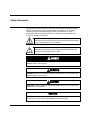
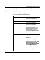
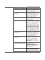
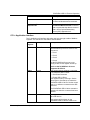
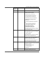
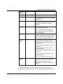
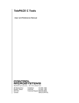
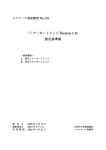
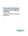
SCADAPack SDI-12 Protocol Driver Installation, Operation and Maintenance Setup Manual 5/19/2011 The information provided in this documentation contains general descriptions and/or technical characteristics of the performance of the products contained herein. This documentation is not intended as a substitute for and is not to be used for determining suitability or reliability of these products for specific user applications. It is the duty of any such user or integrator to perform the appropriate and complete risk analysis, evaluation and testing of the products with respect to the relevant specific application or use thereof. Neither Schneider Electric nor any of its affiliates or subsidiaries shall be responsible or liable for misuse of the information contained herein. If you have any suggestions for improvements or amendments or have found errors in this publication, please notify us. No part of this document may be reproduced in any form or by any means, electronic or mechanical, including photocopying, without express written permission of Schneider Electric. All pertinent state, regional, and local safety regulations must be observed when installing and using this product. For reasons of safety and to help ensure compliance with documented system data, only the manufacturer should perform repairs to components. When devices are used for applications with technical safety requirements, the relevant instructions must be followed. Failure to use Schneider Electric software or approved software with our hardware products may result in injury, harm, or improper operating results. Failure to observe this information can result in injury or equipment damage. © 2010 Schneider Electric. All rights reserved. Document (Version #.##.#) 5/19/2011 Table of Contents Safety Information .........................................................................3 About The Book .............................................................................6 At a Glance ............................................................................................................ 6 Overview .........................................................................................7 SCADAPack SDI-12 Protocol Operation ......................................8 Load SDI-12 C/C++ Program ................................................................................. 8 Load Telepace or IEC 61131-1 application ........................................................... 8 Supported Commands ........................................................................................... 9 C/C++ Application Interface ................................................................................. 11 Document (Version 2.24.1.84) 5/19/2011 2 Safety Information Read these instructions carefully, and look at the equipment to become familiar with the device before trying to install, operate, or maintain it. The following special messages may appear throughout this documentation or on the equipment to warn of potential hazards or to call attention to information that clarifies or simplifies a procedure. The addition of this symbol to a Danger or Warning safety label indicates that an electrical hazard exists, which will result in personal injury if the instructions are not followed. This is the safety alert symbol. It is used to alert you to potential personal injury hazards. Obey all safety messages that follow this symbol to avoid possible injury or death. DANGER DANGER indicates an imminently hazardous situation which, if not avoided, will result in death or serious injury. WARNING WARNING indicates a potentially hazardous situation which, if not avoided, can result in death or serious injury. CAUTION CAUTION indicates a potentially hazardous situation which, if not avoided, can result in minor or moderate. CAUTION CAUTION used without the safety alert symbol, indicates a potentially hazardous situation which, if not avoided, can result in equipment damage.. Document (Version 2.24.1.84) 5/19/2011 3 PLEASE NOTE Electrical equipment should be installed, operated, serviced, and maintained only by qualified personnel. No responsibility is assumed by Schneider Electric for any consequences arising out of the use of this material. A qualified person is one who has skills and knowledge related to the constructi on and operation of electrical equipment and the installation, and has received safety training to recognize and avoid the hazards involved. BEFORE YOU BEGIN Do not use this product on machinery lacking effective point-of-operation guarding. Lack of effective point-of-operation guarding on a machine can result in serious injury to the operator of that machine. CAUTION EQUIPMENT OPERATION HAZARD Verify that all installation and set up procedures have been completed. Before operational tests are performed, remove all blocks or other temporary holding means used for shipment from all component devices. Remove tools, meters, and debris from equipment. Failure to follow these instructions can result in injury or equipment damage. Follow all start-up tests recommended in the equipment documentation. Store all equipment documentation for future references. Software testing must be done in both simulated and real environments. Verify that the completed system is free from all short circuits and grounds, except those grounds installed according to local regulations (according to the National Electrical Code in the U.S.A, for instance). If high-potential voltage testing is necessary, follow recommendations in equipment documentation to prevent accidental equipment damage. Before energizing equipment: Remove tools, meters, and debris from equipment. Close the equipment enclosure door. Remove ground from incoming power lines. Perform all start-up tests recommended by the manufacturer. OPERATION AND ADJUSTMENTS The following precautions are from the NEMA Standards Publication ICS 7.11995 (English version prevails): Document (Version 2.24.1.84) 5/19/2011 4 Regardless of the care exercised in the design and manufacture of equipment or in the selection and ratings of components, there are hazards that can be encountered if such equipment is improperly operated. It is sometimes possible to misadjust the equipment and thus produce unsatisfactory or unsafe operation. Always use the manufacturer’s instructions as a guide for functional adjustments. Personnel who have access to these adjustments should be familiar with the equipment manufacturer’s instructions and the machinery used with the electrical equipment. Only those operational adjustments actually required by the operator should be accessible to the operator. Access to other controls should be restricted to prevent unauthorized changes in operating characteristics. Document (Version 2.24.1.84) 5/19/2011 5 About The Book About The Book At a Glance Document Scope This manual describes the SDI-12 protocol for SCADAPack controllers. Validity Notes This document is valid for all supported SCADAPack controllers. Product Related Information WARNING UNINTENDED EQUIPMENT OPERATION The application of this product requires expertise in the design and programming of control systems. Only persons with such expertise should be allowed to program, install, alter and apply this product. Follow all local and national safety codes and standards. Failure to follow these instructions can result in death, serious injury or equipment damage. User Comments We welcome your comments about this document. You can reach us by e-mail at [email protected]. Document (Version 2.24.1.84) 5/19/2011 6 Overview Overview SDI-12 is a serial communication protocol. SDI-12 is the acronym for Serial Data Interface at 1200 Baud. The SDI-12 protocol is used primarily by environmental monitoring equipment, such as rain gauges, anemometers, etc that are collectively referred to as SDI-12 devices. The SDI-12 protocol is a master-slave protocol with the SCADAPack 32 or SCADAPack 350 controller acting as a master to data monitoring slave SDI-12 devices. The SCADAPack SDI-12 master can communicate with multiple slave devices. SDI-12 encompasses both a hardware communication layer and a software layer. The hardware layer will be accommodated through third party devices. This user manual describes the SDI-12 driver for the SCADAPack 32 and SCADAPack 350 controllers. The SDI-12 protocol is described in SDI-12: A Serial-Digital Interface Standard for Microprocessor-Based Sensors published by the SDI-12 Support Group. Document (Version 2.24.1.84) 5/19/2011 7 SCADAPack SDI-12 Protocol Operation SCADAPack SDI-12 Protocol Operation The SCADAPack SDI-12 protocol support is achieved using a custom C/C++ application for SCADAPack 32 and SCADAPack 350 controllers. The C/C++ application is referred to as the SCADAPack SDI-12 driver in this document. The SCADAPack SDI-12 driver enables the SCADAPack 32 or SCADAPack 350 controller to communicate with SDI-12 devices. The SCADAPack SDI-12 driver supports the commands listed in section Supported Commands. The configuration of the SCADAPack SDI-12 driver is achieved using Telepace or IEC 61131-1 logic programs to write values to Modbus registers. The Modbus registers used by the SCADAPack SDI-12 driver are listed in the table in section C/C++ Application Interface. Sample Telepace and IEC 61131-1 applications are included with this documentation package to demonstrate the use of Modbus registers to configure the SCADAPack SDI-12 driver. Load SDI-12 C/C++ Program Using Telepace or IEC 61131-1 load the SCADAPack SDI-12 C/C++ application into the SCADAPack 32 or SCADAPack 350 controller. The C/C++ application will depend on the controller and firmware type you are using. For SCADAPack 32 controller with Telepace firmware load sp32Telepace.mot For SCADAPack 32 controller with IEC 61131-1 firmware load sp32ISaGRAF.mot For SCADAPack 350 controller with Telepace firmware load sp350Telepace.out For SCADAPack 350 controller with IEC 61131-1 firmware load sp350ISaGRAF.out Once the program is written to the SCADAPack controller check that the Run button is clicked in the C/C++ Program Loader. Load Telepace or IEC 61131-1 application The SCADAPack SDI-12 package includes an example Telepace application and an example IEC 61131-1 application. These example applications can be used as a basis for a complete SDI-12 interface. For SCADAPack 32 or SCADAPack 350 controllers with Telepace firmware the example program is sdi12.lad. For SCADAPack 32 or SCADAPack 350 controllers with IEC 61131-1 firmware the example program is sdi12.pia. Document (Version 2.24.1.84) 5/19/2011 8 SCADAPack SDI-12 Protocol Operation The logic application, either Telepace or IEC 61131-1, is programmed to use the Modbus registers defined in the C/C++ Application Interface section. Supported Commands The SCADAPack SDI-12 driver includes the basic SDI-12 commands listed in Table 5 of the SDI-12: A Serial-Digital Interface Standard for Microprocessor-Based Sensors Version 1.3 document. A brief description of each supported command is listed in the table below. Command Description Send Identification (I) This command is used to query sensors for their SDI-12 compatibility level, model number, and firmware version number. Change Address (A) This command is used to change the address of a connected sensor. Address Query (?) This command is used to query the address of a connected sensor. Start Measurement (M) This command tells the sensor to take a measurement. The sensor does not return the measurement data to the SCADAPack after this command. The sensor returns the time until one or more measurements will be ready and the number of measurements that it will make. The Send Data command needs to be issued to get the measurement(s). Start Measurement and Request CRC This command is identical to the Start Measurement command with a request that the data be returned with a 16 bit Cyclical Redundancy Check (CRC) appended to it. Send Data This command is used to get groups of data from the sensor. The Send Data command is sent automatically by the SCADAPack SDI-12 driver after a Start Measurement and Request CRC, Start Concurrent Measurement, Start Concurrent Measurement and Request CRC or Start Verification command is enabled in the user logic application. The SDI-12 device responds by sending data. Additional Measurements The Additional Measurements commands provide a means to request Document (Version 2.24.1.84) 5/19/2011 9 SCADAPack SDI-12 Protocol Operation Command Description different types of measurements from a sensor or to instruct a sensor to do a calibration or control function. Additional Measurements and Request CRC This command is identical to the Additional Measurements command with a request that the data be returned with a 16 bit Cyclical Redundancy Check (CRC) appended to it. Start Verification (V) This command tells the sensor to return verification in response to a subsequent send data command. Start Concurrent Measurement (C) This command tells the sensor to take a concurrent measurement. A concurrent measurement is one which occurs while other SDI-12 sensors on the bus are also taking measurements. The sensor does not return the measurement data to the SCADAPack after this command. The sensor returns the time until one or more measurements will be ready and the number of measurements that it will make. The Send Data command needs to be issued to get the measurement(s). Start Concurrent Measurement and Request CRC This command is identical to the Start Concurrent Measurement command with a request that the data be returned with a 16 bit Cyclical Redundancy Check (CRC) appended to it. Additional Concurrent Measurements The Additional Concurrent Measurements commands provide a means to request different types of measurements from a sensor or to instruct a sensor to do a calibration or control function Additional Concurrent Measurements and Request CRC This command is identical to the Additional Concurrent Measurements command with a request that the data be returned with a 16 bit Cyclical Redundancy Check (CRC) appended to it. Continuous Measurements (R) A Start Measurement command is not needed for sensors that are able to continuously monitor the phenomena to be measured, such as a shaft encoder Document (Version 2.24.1.84) 5/19/2011 10 SCADAPack SDI-12 Protocol Operation Command Description They can be read directly with the Continuous Measurements command. Continuous Measurements and Request CRC This command is identical to the Continuous Measurements command with a request that the data be returned with a 16 bit Cyclical Redundancy Check (CRC) appended to it. C/C++ Application Interface The C application will interface with other user logic through a table of Modbus registers. The structure for this table is defined below. Modbus Register SDI-12 Function Description 41001 Comm Port This register defines which serial communications port will be used for SDI12 protocol. 1 = Com 1 2 = Com 2 3 = Com3 4 = Com 4 Set the SCADAPack Com port to use writing a value to this register at start-up. Com3 on the SCADAPack 32 is not supported for SDI-12. 41003 Control This register defines sending a command, or to restart the SDI-12 driver. 1 = Send Data Command 2 = Restart SDI-12 Driver This register is set by user logic. Set the control type to 0 at start up to restart the SCADAPack SDI-12 driver. Set the control type to 1 to initiate a command to the SDI12 device. The SCADAPack SDI-12 driver resets the register to 0 when the command has been initiated. 41005 Address This register indicates the address of the slave SDI device. This register will be written by the SCADAPack SDI-12 after a restart or an Document (Version 2.24.1.84) 5/19/2011 11 SCADAPack SDI-12 Protocol Operation Modbus Register SDI-12 Function Description Address Query command. 41007 Command This register defines the SDI-12 command to send to the SDI-12 device. 1 = Address Query command (?) 2 = Send Identification command (I) 3 = Change Address command (A) 4 = Start Measurement command (M) 5 = Start Concurrent Measurement command (C) 6 = Continuous Measurement command (R) 7 = Start Verification command (V) 8 = Start Additional Measurement command (Mn) (see Note 2) 9 = Start Additional Concurrent Measurement command (Cn) This register is set by user logic to indicate which command to send. 41009 Checksum This register defines whether to request CRC on slave SDI-12 response messages. 0 = No CRC requested 1 = CRC requested This register is set by user logic to indicate whether a CRC is requested or not. 41011 Timeout This register defines how long the SCADAPack SDI-12 driver will wait for a response from the SDI-12 device. This register is set in units of 100 mS i.e. a value of 100 represents 10 seconds. 41013 Status The SCADAPack SDI-12 driver will write to this register to indicate the status of the SDI message transaction: 0 = command completed OK 1 = message pending 2 = data error 41015 Success Counter Document (Version 2.24.1.84) 5/19/2011 The SCADAPack SDI-12 driver will write to this register indicating the umber of 12 SCADAPack SDI-12 Protocol Operation Modbus Register SDI-12 Function Description successful SDI messages. 41017 Fail Counter The SCADAPack SDI-12 driver will write to this register indicating the number of failed SDI messages. 41019 New Fail Counter The SCADAPack SDI-12 driver will write to this register indicating the number of failed messages since the last successful message. 41021 Data length Indicates the number of data bytes in the SDI-12 response message. This will be written by the SCADAPack SDI-12 driver after each received SDI-12 response message. 41023 Poll Delay The number of milliseconds to delay polling a device. This parameter is used to allow devices that are slower to wake from low power mode to be communicated with. 41100 41139 Data Values Floating point values representing the data values returned from the SDI-12 slave device. Up to a maximum of 20 data values can be returned. First data value FP register 41100 (41100 and 41101) Second data value FP register 41102 (41102 and 41103) Third data value FP register 41104 (41104 and 41105) ………. Twentieth data value FP register 41138 (41138 and 41139) IEC 61131-1 register ordering is used. 41200 41239 Raw Data Values The raw data bytes returned from the SDI device will be stored in these registers. This is useful for storing the SDI-12 identification string from the SDI-12 slave device. The Modbus Register numbers are spaced apart to allow for IEC 61131-1 applications to assign each variable to a (32-bit) integer variable without overlap. Document (Version 2.24.1.84) 5/19/2011 13 SCADAPack SDI-12 Protocol Operation The first SDI Raw Data Register (Modbus address 41200) is used to send the data value for the following commands: Change Address Start Additional Measurement Start Additional Concurrent Measurement Document (Version 2.24.1.84) 5/19/2011 14