1
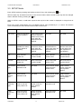
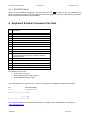
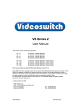
VQ-Series Real Time Splitter
User Manual
Products covered by this manual:
VQ-402M
Monochrome Real-Time Quad and PIP
VQ-402C
Colour Real-Time Quad and PIP
VQ-403C
Colour Real-Time Quad, PIP, Dual PIP, Vertical Split, Horizontal Split
Document Ref: Vq601c.doc
Date:
04/08/2004
Videoswitch
Telephone
01252-851510
Units 15 & 16
Fax
01252-851296
Redfields Industrial Park
Email
[email protected]
Redfields Lane
Web
www.videoswitch.co.uk
Church Crookham
Hants GU52 0RD
VQ-Series Real Time Splitter
Videoswitch
User Manual
2
04/08/2004 17:25
Vq601c.doc
VQ-Series Real Time Splitter
User Manual
04/08/2004 17:25
Contents:
1
Installation ................................................................................................................................4
1.1
Connecting Up..............................................................................................................................................................................4
1.2
Termination ..................................................................................................................................................................................4
2
Operation...................................................................................................................................4
2.1
Power-Up .....................................................................................................................................................................................4
2.2
Multi-Screen Selection .................................................................................................................................................................4
2.3
Full Screen Selection ...................................................................................................................................................................5
2.4
Auto-Sequencing..........................................................................................................................................................................5
2.5
Remote Keyboard ........................................................................................................................................................................5
3
Configuration ...........................................................................................................................5
3.1
Restore Factory Defaults..............................................................................................................................................................5
3.2
Set Remote Control Address .......................................................................................................................................................5
3.3
SETUP Mode ...............................................................................................................................................................................6
3.3.1
4
Exit SETUP Mode ........................................................................................................................................................................................ 7
Keyboard & Alarm Connector Pin-Outs............................................................................7
Videoswitch
3
Vq601c.doc
VQ-Series Real Time Splitter
User Manual
04/08/2004 17:25
1 Installation
1.1 Connecting Up
The diagram below shows the connector arrangement on the rear panel (unit viewed from rear). Note that
lettering for the camera numbers on the actual rear panel may be in error; this diagram shows the correct
numbering:
MONITOR
OUTPUTS
VQ REAL TIME SPLITTER
4
3
2
1
KBD & ALARM
12V DC INPUT
•
Connect cameras to BNC inputs (1, 2, 3 and 4 lower row). If the unit is being used just as a two-way
horizontal or vertical splitter (VQ-403C only), connect cameras to inputs 1 and 2 only.
•
If required, loop through cameras to other equipment (1, 2, 3 and 4 upper row)
•
Connect monitor(s) to BNC and/or S-Video outputs.
•
Plug in the 12V power supply to the 3-pin Mini-DIN connector.
•
If alarms are to be used, connect normally open contacts KBD & ALARM connector (refer to section
4).
•
If a remote keyboard is to be used, connect twisted pair to KBD & ALARM connector (refer to
section 4).
1.2 Termination
In normal use where the camera signals connect only to this quad, the four DIL switches under the unit
should all be ON.
If cameras are looped through to other equipment that terminates the video, then the corresponding DIL
switch sections should be turned OFF.
2 Operation
2.1 Power-Up
Plug the flying lead of mains power adaptor into the “+12V DC” power input connector. Plug the adaptor
itself into the mains supply.
2.2 Multi-Screen Selection
Press the
key to step through the available multi-screen modes.
The screen modes that are provided on the different models are:
Videoswitch
4
Vq601c.doc
VQ-Series Real Time Splitter
Model
User Manual
Modes
VQ-402M
•
Full Screen
VQ-402C
•
Quad,
•
PIP (picture in picture)
•
Full Screen
•
Quad
•
PIP
•
Dual PIP
•
Vertical Split
•
Horizontal Split
VQ-403C
04/08/2004 17:25
2.3 Full Screen Selection
To display a full screen image, press camera key 1, 2, 3 or 4.
2.4 Auto-Sequencing
To switch auto-sequencing ON, press and hold a camera key, then momentarily press the
cancel auto-sequencing, press any camera key or select a multi-screen mode.
key. To
2.5 Remote Keyboard
The unit may be remotely controlled by any Videoswitch VK-series remote keyboard, or by a computer
running suitable software.
3 Configuration
A number of user preferences may be configured using the SETUP mode. These settings are stored when
power is removed. The factory default settings can be easily restored to provide known starting conditions.
Note that all cameras should be connected when using SETUP mode so that you can see the effects of any
changes made. This unit does not generate on-screen text.
3.1 Restore Factory Defaults
To restore the factory defaults, hold the ALT key on while turning on the power.
Note that the default screen mode is QUAD.
3.2 Set Remote Control Address
The address that the unit uses for control via a remote keyboard is set as follows:
To set the unit address, hold the ALT key and one of the camera select keys (1, 2, 3 or 4) while turning on
the power. The unit address will be set to 1, 2, 3 or 4 respectively.
Videoswitch
5
Vq601c.doc
VQ-Series Real Time Splitter
User Manual
04/08/2004 17:25
3.3 SETUP Mode
Enter SETUP mode by pressing and holding on the ALT key, then pressing the
key.
SETUP mode may be entered from any of the screen modes, and the screen mode may also be changed
while in SETUP mode by pressing the
key.
While in SETUP mode, a small black square at the top left of the screen is displayed or a larger area of
black.
Each of the screen modes allows you to set different things, using camera keys 1, 2, 3 and 4. The function
of the camera keys for each SETUP screen mode is shown here:
1
2
3
4
Full Screen
Press to toggle autosequencing ON or
OFF.
Press once to start
the auto sequence
DWELL timer. Press
again when the
required time has
elapsed.
Not used
Not used
Quad
Press to ENABLE or
DISABLE the alarms
(factory default is
ENABLE).
Press to start alarm
HOLD time. Press
again when the
required time has
elapsed.
Press to start alarm
SEQUENCE time.
Press again when the
required time has
elapsed.
Press to start alarm
RELAY HOLD time.
Press again when
the required time
has elapsed.
PIP
Move main PIP
position UP
Move main PIP
position DOWN
Move main PIP
position LEFT
Move main PIP
position RIGHT
Dual PIP
Move second PIP
position UP
Move second PIP
position DOWN
Move second PIP
position LEFT
Move second PIP
position RIGHT
Left Vertical
Split
Select vertical
SQUASH mode
Not used
Select vertical CROP
mode and move
position LEFT
Select vertical
CROP mode and
move position
RIGHT
Right
Vertical
Split
Select vertical
SQUASH mode
Not used
Select vertical CROP
mode and move
position LEFT
Select vertical
CROP mode and
move position
RIGHT
Upper
Horizontal
Split
Select horizontal
CROP mode and
move position UP
Select horizontal
CROP mode and
move position
DOWN
Select horizontal
SQUASH mode
Not used
Lower
Horizontal
Split
Select horizontal
CROP mode and
move position UP
Select horizontal
CROP mode and
move position
DOWN
Select horizontal
SQUASH mode
Not used
Videoswitch
6
Vq601c.doc
VQ-Series Real Time Splitter
User Manual
04/08/2004 17:25
3.3.1 Exit SETUP Mode
When you have finished configuration, press the ALT key and
key again to quit. All settings will be
saved, including the screen mode being displayed when this is done. If no keys are pressed for 30 seconds,
SETUP mode will automatically be terminated.
4 Keyboard & Alarm Connector Pin-Outs
Pin
Description
1
2
3
4
5
6
7
8
9
10
Alarm 2
Alarm 4
Do not connect
Do not connect
Ground
Alarm 1
Alarm 3
Do not connect
Do not connect
Connect to Pin 15 to terminate the RS485 input unless
the twisted pair is being daisy-chained to another
terminated device.
Relay Normally Open
Relay Common
Relay Normally Closed
Remote Keyboard Input (RS485+)
Remote Keyboard Input (RS485-)
11
12
13
14
15
For RS232 remote control:
• Connect Pin 14 to Pin 5
• Connect RS232 data (TXD) to Pin15
• Connect RS232 ground to Pin 5
The cable required for control from a PC with a 9-way D-type on its RS232 (COM) port is as follows:
PC
===
VQ-Series Splitter
==============
3-----------------------------------15
|----------14
5------------------------|-----------5
The VQ-Series Splitter can be controlled using the PC “VDM-Remote”, available free of charge from
www.videoswitch.co.uk.
Videoswitch
7
Vq601c.doc