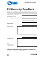
1
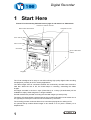
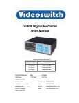
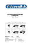
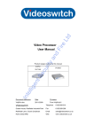
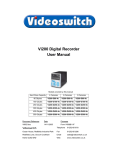
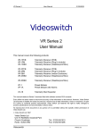
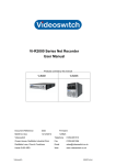
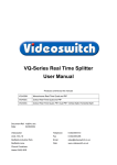
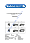
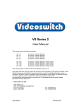
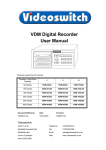
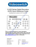
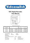
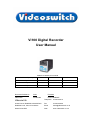
Vi100 Digital Recorder
User Manual
Models covered by this manual
Hard Drive Capacity
4 Cameras
80 Gbytes
Vi100-G80-4
160 Gbytes
6 Cameras
9 Cameras
Vi100-G160-6
Vi100-G160-9
250 Gbytes
Vi100-G250-9
Document Reference
Date
Firmware
Vi601d.doc
30/09/2005
From Vi008B10/F
Videoswitch
Telephone
01252-851510
Ocean House, Redfields Industrial Park
Fax
01252-851296
Redfields Lane, Church Crookham
Email
[email protected]
Hants GU52 0RD
Web
www.videoswitch.co.uk
Vi601d.doc
Digital Recorder
Contents:
1
Start Here ..................................................................1
1.1
Connecting Up .......................................................................................................................2
1.2
Setting Date/Time ..................................................................................................................3
1.3
Recording...............................................................................................................................4
1.4
Routine Checks......................................................................................................................4
1.5
Care of the Hard Drive ...........................................................................................................4
1.6
Critical Alerts ..........................................................................................................................5
2
LIVE ...........................................................................6
2.1
Viewing Full Screen Images ..................................................................................................6
2.2
Quad Display..........................................................................................................................6
2.3
9-way Multi-Screen ................................................................................................................7
3
FIND ...........................................................................8
3.1
FIND-1 Date/Time ..................................................................................................................8
3.2
FIND-2 Sweep........................................................................................................................9
3.3
FIND-3 Event List.................................................................................................................10
4
5
6
PLAY........................................................................11
BURN .......................................................................13
PSW .........................................................................14
6.1
Log-On .................................................................................................................................14
6.2
Log-Off .................................................................................................................................15
7
FN.............................................................................16
7.1
Auto sequence - Yes............................................................................................................16
7.2
Auto sequence - No .............................................................................................................16
8
9
INFO.........................................................................17
MENU.......................................................................18
9.1
9.1.1
9.1.2
9.2
Date/Time.............................................................................................................................19
Date/Time ........................................................................................................................19
Summer/Winter Time .......................................................................................................20
Display .................................................................................................................................20
9.2.1
Keypad Brightness...........................................................................................................20
9.2.2
Auto Seq Dwell ................................................................................................................20
9.2.3
Camera Titles...................................................................................................................20
9.3
Activity Detection .................................................................................................................21
9.4
Configuration........................................................................................................................21
9.4.1
User Password.................................................................................................................21
9.4.2
Covert Cameras ...............................................................................................................21
9.4.3
Camera Inputs .................................................................................................................22
9.4.3.1
Record Brightness
22
9.4.3.2
Record Colour Boost
22
9.4.4
Restore Factory Config ....................................................................................................22
9.4.5
Erase Hard Drive .............................................................................................................22
10 Remote Keyboard...................................................23
11 Dial-Up Access .......................................................24
11.1
Vi-PSTN ...............................................................................................................................24
11.2
Connecting a Dial-up Adaptor ..............................................................................................24
1
Digital Recorder
12 Technical Data ........................................................25
12.1
Power-On Reset ..................................................................................................................25
12.2
Changing the Hard Drive .....................................................................................................25
12.3
Accessories Included ...........................................................................................................25
12.4
Connector Pin-Outs .............................................................................................................26
12.4.1
Alarms ..............................................................................................................................26
12.4.2
Remote Keyboard ............................................................................................................27
12.4.3
PSTN/ISDN Modem.........................................................................................................28
12.5
Image Capture and Storage.................................................................................................28
12.6
Physical and Environmental.................................................................................................29
12.6.1
Power Requirements .......................................................................................................29
12.6.2
CE Marking ......................................................................................................................29
12.6.3
Dimensions and Weight ...................................................................................................29
12.6.4
Temperature and Humidity ..............................................................................................29
12.6.5
Ventilation ........................................................................................................................29
12.6.6
Safety...............................................................................................................................29
13 Warranty Fax-Back .................................................31
2
Digital Recorder
1 Start Here
Please fill in the warranty fax-back form on page 31 and return it to Videoswitch
Hard drive drawer handle
Removable Hard Drive
Hard Drive Lock
Disc Activity LED
Disc Power LED
CD Writer
Open CD drawer
button
Keypad
The Vi100 is designed to be easy to use whilst offering high quality digital video recording
and playback, primarily for CCTV security applications.
The video images from all connected cameras are continuously recorded onto the built-in
hard disc. When the disc is full, the Vi100 keeps on recording, overwriting the oldest
images.
All images recorded in the last 7 days (Vi100-G80-4) or 14 days (Vi100-G160-9) will be
available for replay. Older image are no longer available.
Several methods are provided for finding the recorded images you want quickly.
The built-in CD writer allows a selected part of the recorded information to be written onto a
CD, typically to back-up an incident for use as evidence by the Police.
The recording process continues all the time, even when playing back or writing to CD.
An optional dial-up module allows images to be viewed on a PC (with a modem) via a
telephone line.
1
Digital Recorder
1.1 Connecting Up
For a standard digital recording system you will need
The Vi100 recorder
Some cameras with lenses
A video monitor (with BNC composite video input).
BNC cables
Rear View
Connect the monitor output (MAIN) of the Vi100 to a Video Monitor to the using a BNC
cable
Make sure that the monitor termination is switched on (i.e. to 75 Ohms)
Connect the a camera to Camera Input 1 on the Vi100 using a BNC cable
Connect further cameras to Inputs 2,3,4 etc
Make sure that the voltage select switch is set to suit the mains supply. The setting
required in UK and Europe is 230Vac.
2
Digital Recorder
Connect the mains power using main cable provided
1.2 Setting Date/Time
For proper operation of the Vi100 Digital Recorder it is essential that the date and
time are set correctly.
If the system clock has an invalid date or time when the Vi100 is powered up (or at any time
during operation), the date and time setting window will be automatically displayed
If this occurs, use the number keys to enter the date and time.
1
4
7
2
3
5
6
8
9
0
The format for the date and time is DD/MM/YY HH:MM:SS
where:
•
DD is the day of the month (00 to 31),
•
MM is the month (01 to 12),
•
YY is the year (e.g. 04 for the year 2004),
•
HH is the hour in 24-hour format (00 to 23),
•
MM is the number of minutes past the hour (00 to
59) and
•
SS is the number of seconds past the minute (00 to
59).
The arrow keys may be used to move the cursor to different positions if only some digits
need changing:
Í
Í
Press OK to finish:
OK
If you need to adjust the time and date at any other time, refer to section 9.1. Note that the
time is automatically adjusted forwards or backwards by an hour at the appropriate dates to
take account of British Summertime so no user action is required.
3
Digital Recorder
1.3 Recording
The Vi100 Digital Recorder should now be fully operational and recording images from all
cameras. The default image retention period is 7 days for the Vi100-G80-4 and 14 days for
the Vi100-G160-9.
1.4 Routine Checks
If the Vi100 is not recording, the message STOP will be displayed on top right of the video
monitor. This should only happen if no hard drive is fitted or if it is faulty.
Although the system is intended for continuous un-attended operation, it is recommended
that the user regularly check that images from all cameras replay correctly. Any
potential problems with the cameras or recording system will then be detected as soon a
possible, rather than continuing un-noticed until a critical incident needs to be recalled from
the system.
Similarly, when a CD has been created you should check that it plays back correctly,
before the images on the hard drive in the Vi100 become over-written. The CD may be
checked by either by playing it on the Vi100 or on a PC.
1.5 Care of the Hard Drive
The hard drive is a delicate mechanical item that should be handled with care. Before
moving a Vi100 that has been powered up, remove power and wait for 30 seconds for the
drive to stop spinning. This is a precaution to avoid possible damage to the hard drive.
4
Digital Recorder
1.6 Critical Alerts
The Vi100 constantly monitors the hard drive, camera inputs and system so that detected
fault conditions will be reported to the user as soon as possible by means of a “critical alert”
message on the screen. Alerts are also added to the event list.
• FailTest
This alert indicates that the self-test has failed – try the following
o
Press the INFO key to call up the “FIND-2 Status” screen.
The positions of any solid blocks displayed on the “Self Test” row
indicate various fault conditions.
o
Enter the menu, change any setting and return to LIVE mode so
that settings are saved.
o
Switch off the Vi100, wait 10 seconds and switch on again.
o
Try a power-on reset (See section 0).
o
If the problem persists, contact your supplier.
• HD1 Fail
This alert indicates that the hard drive is not working.
o
Check that the drive drawer is correctly fitted
o
Check the lock in the drive drawer is turned full counterclockwise
o
Check the DISC ACTIVITY LED is flickering (see diagram in
section 1)
o
Check that the red DISC POWER led it lit.
• HD1 SMART
This alert indicates that the hard drive may stop working soon
o
The SMART monitoring detects imminent failure of a hard drive,
so if this warning occurs, the drive should be changed at the
earliest opportunity.
To cancel a critical alert, press the FIND key several times until the “FIND-3 Event”
screen is displayed.
F IN D
The time of alert will be displayed on the list (see section 3) and the alert will be cancelled.
Note that if the alert condition persists, the alert message will re-appear.
5
Digital Recorder
2 LIVE
Press this key to view live images:
LIVE
This key may be pressed at any time to exit from any other screen.
2.1 Viewing Full Screen Images
Select full screen views of different cameras by pressing the NUMBER keys:
1
2
3
4
5
6
7
8
9
0
To step forwards or backwards through the cameras displayed on the main monitor, press
one of these keys:
INC
DEC
2.2 Quad Display
Select quad display by pressing the QUAD key (live display only):
6
Digital Recorder
2.3 9-way Multi-Screen
Select x9 Multi-Screen display by pressing the MULTISCREEN key (live display only):
Note: this applies only to 9-camera model.
7
Digital Recorder
3 FIND
If there is a CD in the CD drive with previously stored images on it, the Vi100 will
replay from the CD. Otherwise, the Vi100 will replay from the built-in hard drive.
3.1 FIND-1 Date/Time
This mode is finds images by date and time. Press
this key to enter the Date/Time search mode:
Sometimes it is useful to press the
DEF key when in search mode, to call
up the latest available recorded
images
F IN D
Use the NUMBER keys to enter
any date and time for which there
is still video available.
1
4
7
2
3
5
6
8
The format for the date and time is DD/MM/YY
HH:MM:SS where:
•
DD is the day of the month (00 to 31),
•
MM is the month (01 to 12),
•
YY is the year (e.g. 04 for the year 2004),
•
HH is the hour in 24-hour format (00 to 23),
•
MM is the number of minutes past the hour
(00 to 59) and
•
SS is the number of seconds past the
minute (00 to 59).
9
0
Scroll through dates and times using the ARROW
keys:
Í
Í
Note that as any digit of the date
and time is changed, the
corresponding
image
is
immediately found on the hard
drive and displayed.
the
Í
Í
This is
facility.
When you have found what you want, use the play keys to view the video:
8
“active
search”
Digital Recorder
3.2 FIND-2 Sweep
An alternative to the date/time search, is the sweep facility. Press this key until the sweep
mode is displayed:
F IN D
Use these keys to scan through the whole
range of recorded images:
Í
Í
To step in finer time increments, press the
OK key to access the fine mode.
Note that the slider changes from a solid
block to a diamond.
Press again to cancel.
To quickly step between start, middle and end, press this key:
DE F
When you have found what you want, use the play keys to view the video:
9
Digital Recorder
3.3 FIND-3 Event List
If alarm contacts are being used, there may be events in the event list. Press FIND key
until the event screen is displayed:
Entering the EVENT screen clears
any critical alert conditions. If a critical
alert problem still exists, new alert
events will be created.
F IN D
Use the up/down keys to scroll through events
and the left/right keys to select different pages
of events.
As events are highlighted, the
corresponding
image
will
be
immediately recalled and displayed.
Í
Í
Up to 480 events can be recorded
before older ones are over-written.
Í
Í
Press this key to go to the latest event:
DE F
When you have found what you want, use the play keys to view the video:
10
Digital Recorder
4 PLAY
If there is a CD in the CD drive with previously stored images on it, the Vi100 will
replay from the CD. Otherwise, the Vi100 will replay from the built-in hard drive.
Having found what you want using the FIND key,
you can use these keys to move forwards and
backwards through the recorded video images.
Press the forward or reverse play
keys repeatedly to increase the
replay speed.
The function of each key is:
Step backwards one image
Step forwards one image
Play backwards (press again to increase speed)
Play forwards (press again to increase speed)
Pause at currently displayed image
View different cameras by pressing the NUMBER keys:
1
2
3
4
5
6
7
8
9
0
To step forwards or backwards through the cameras displayed on the main monitor, press
one of these keys:
11
Digital Recorder
INC
DEC
12
Digital Recorder
5 BURN
To burn a section of video recording to CD you must go to the middle of the incident that
you wish to backup, using the FIND and PLAY facilities as described in sections 3 and 4.
Then do the following:
Call up the BURN screen by pressing this key.
If there is a CD in the CD drive
that is not blank, the BURN
screen will not be displayed.
BURN
Create an “incident” by pressing this key.
DE F
Change the duration of the incident as
required using the left/right keys:
Í
Í
The start and end times can also be
individually adjusted by using the UP and
DOWN arrow keys to highlight the start or
end times, and the LEFT and RIGHT keys to
adjust the time.
Alternatively if you highlight the start time and
press DEF it will be set to the current play
image. Similarly if you highlight the end time
and press DEF it will be set to the current play
image.
Press the “Open CD drawer” button on the CD drive and place a new CD-R in the CD drive.
Press the “Open CD drawer” button again to close the drawer.
Start writing to CD by pressing this key:
OK
13
Note that you can only write incidents to a
blank CD. When an important incident has
been written to a CD, always check that the
CD plays back correctly, either by playing it
on the VI100 or on a PC.
Digital Recorder
6 PSW
A password may be set in the menu to prevent unauthorised access to the menu (see
section 9.4.1).
6.1 Log-On
To log-on to the Vi100 and thereby gain access to the menus:
Press this key:
PSW
Enter the correct password using the NUMBER keys:
1
2
3
4
5
6
7
8
9
0
Press this key:
OK
A message on the screen will indicate whether user access has been granted. If it has, the
menus may now be entered.
14
Digital Recorder
6.2 Log-Off
When you have finished accessing the menu, you should log-off again to prevent other
users gaining unauthorised access:
Press this key:
PSW
Press this key:
OK
The menus are now protected again.
15
Digital Recorder
7 FN
The “FN” key provides additional functions as listed below:
7.1 Auto sequence - Yes
Press these keys to start auto-sequencing of all cameras on the monitor
FN
7
OK
7.2 Auto sequence - No
Press these keys to stop auto-sequencing of all cameras on the monitor
FN
8
OK
16
Digital Recorder
8 INFO
A number of information screen are available to tell you about the Vi100 and to confirm that
it is operating in the way that you intend:
•
INFO-1
Configuration
•
INFO-2
Status
•
INFO-3
Drives
•
INFO-4
Record
•
INFO-5
Play
Press this key to step through these various information screens:
INFO
To return to viewing live images, press this key:
LIVE
17
Digital Recorder
9 MENU
To enter the menu, press this key:
MENU
Changes within the menu system require the use of the following keys:
The ARROW keys are used to move through the menus and to alter settings within the
menu:
Í
Í
Í
Í
If you are uncertain about a menu setting, the default option can be selected using this key:
DE F
In parts of the menu you may need to initiate an action by pressing the OK key:
OK
In parts of the menu you may need to enter numbers using the NUMBER keys:
1
2
3
4
5
6
7
8
9
0
To exit the menu, press this key:
LIVE
18
Digital Recorder
9.1 Date/Time
For proper operation of the Vi100 Digital Recorder it is essential that the date and
time are set correctly.
9.1.1
Date/Time
When you have found this menu item (see start of section 9), press this key to start editing
the date and time:
OK
Use the NUMBER keys to
enter the date and time:
1
4
7
2
3
5
6
8
9
The format for the date and time is DD/MM/YY
HH:MM:SS where:
•
DD is the day of the month (00 to 31),
•
MM is the month (01 to 12),
•
YY is the year (e.g. 04 for the year 2004),
•
HH is the hour in 24-hour format (00 to 23),
•
MM is the number of minutes past the hour
(00 to 59) and
•
SS is the number of seconds past the minute
(00 to 59).
0
The arrow keys may be used to move the cursor to different positions if only some digits
need changing:
Í
Í
Press OK to finish:
OK
19
Digital Recorder
9.1.2
Summer/Winter Time
If this menu item is set to Automatic, the displayed time and date will automatically change
in spring and autumn. If you are in a country with different light saving hours, you can use
this menu item to manually select summer-time (1 hour ahead) or winter-time. The date/time
setting in section 9.1 should not be changed other than to adjust and drift in the timekeeping
of the Vi100.
9.2 Display
9.2.1
Keypad Brightness
The brightness of the backlit keypad may be adjusted here using the UP and DOWN keys
or the NUMBER keys.
9.2.2
Auto Seq Dwell
When auto-sequencing cameras (see section 7.1), the dwell time is specified by this option
using the NUMBER keys.
9.2.3
Camera Titles
Each camera may be given a title, or the default title may be used (“Camera1”, “Camera2”
etc).
You can use the NUMBER keys for numbers and the UP and DOWN arrow keys to get
letters and other characters. Or use the + and – keys to scroll through the units preset titles.
Press the BACK or LEFT key to go back to the previous menu level.
20
Digital Recorder
9.3 Activity Detection
Activity detection zones may be set for each camera.
Use the UP and DOWN keys to highlight different rows.
If you select the top (text) row, the sensitivity and pixel count can be set.
The sensitivity affects all selected pixels (zones). The higher this setting, the more sensitive
the activity detection is.
•
Use the NUMBER keys 1-4 to set sensitivity (Sen)
The pixel count specifies the number of zones that have to be simultaneously active in order
to trigger an activity alarm (i.e. the higher the pixel count, the lower the chance of triggering)
•
Use the NUMBER keys 5-9 to set the number of pixels (Pix)
As you select the various rows over the image, the NUMBER keys turn the zones across
the line on and off. If a zone is turned on, it will be sensitive to changes in the image.
The DEF key may be used to toggle all zones one or off.
9.4 Configuration
9.4.1
User Password
The default password for the unit is all ones but if you wish to set a password, enter a six
digit number here. Enter all zeros to remove the password.
When a password has been set, access to the menu will be prohibited until the user “logs
on” by pressing the PSW key and entering the correct password.
Note that CD burning will also be prevented if any cameras have been set as covert (see
below).
If you set a password, be very careful to make sure that it is recorded, otherwise access to
the menus will not be possible again.
9.4.2
Covert Cameras
One or more cameras may be set as covert (hidden). Make sure a non-zero password has
been set (see above) to prevent unauthorised access to this menu.
If you now want to view covert cameras, press the PSW key and enter the correct
password. Remember to log off (enter no password) when you have finished viewing.
Note: Do not use Camera 1 as a covert camera.
21
Digital Recorder
9.4.3
Camera Inputs
9.4.3.1 Record Brightness
The brightness of the images being recorded can be adjusted to compensate for cable
losses. Adjust the brightness as required for each camera.
•
If the displayed image (which is digitised) is too dim or is tearing, increase the
brightness setting.
•
If an image is too bright, decrease the brightness setting.
9.4.3.2 Record Colour Boost
The colour content of the images being recorded can be adjusted here to compensate for
cable losses. Adjust so that the colour content of the displayed image is not too weak or too
strong.
9.4.4
Restore Factory Config
Press the YES key to restore the configuration to the factory defaults.
9.4.5
Erase Hard Drive
Press the YES key to erase the hard drive.
22
Digital Recorder
10 Remote Keyboard
A remote keyboard may be connected to the Vi100 to provide control from another room.
Simply connect the Vi100 to the keyboard using Cat 5 (or similar twin twisted pair cable).
Connect the keyboard to a monitor using a BNC co-ax cable. All the keys of the Vi100 are
duplicated on the remote keyboard and the Vi100 may be controlled in the same way.
If the keyboard is more than about 100 metres away from the Vi100, then the monitor
should be connected to the Vi100 separately via a BNC cable (RG59) to ensure best picture
quality. The CAT5 data connection should operate up to 500 metres.
CAT5
Vi100
MONITOR
CO-AX
Digital
Recorder
OUT
MON
Vi-K1 or Vi-K2
KEYBOARD
23
Digital Recorder
11 Dial-Up Access
Images may be viewed on a PC via a telephone line (PSTN) if an optional external Vi-PSTN
adaptor is attached.
11.1 Vi-PSTN
This external adaptor is for use with a standard telephone line. The adaptor plugs into the
PSTN/ISDN connector on the Vi100. A PC with a modem is required to view the images.
Software for the PC is provided with the adaptor.
11.2 Connecting a Dial-up Adaptor
•
Connect the Vi-PSTN adaptor to the Vi100 using the 9-way D-type cable provided
with the adaptor. No power supply is required.
•
Connect the adaptor to the telephone socket using the cable provided with the ViPSTN adaptor.
•
Install Vi-Connect software in the PC that is to be used to dial into the Vi100. A
modem must be fitted for PSTN use.
Vi100
Digital
Recorder
Vi-ISDN
or
VI-PSTN
PSTN
Phone socket
24
Digital Recorder
12 Technical Data
12.1 Power-On Reset
If you wish to perform a power-on-reset to restore all settings to their factory defaults, press
the DEF key while you apply power, and keep pressing it until the Vi100 has powered up
and displays FACTORY RESET. Note that this process will reset all user settings, including
camera titles and password. The DEF key will need to be pressed for about 10 seconds.
The factory configuration can also be recalled via the menu (see section 9.4.4).
12.2 Changing the Hard Drive
Hard drives are sensitive mechanical devices that may be damaged by shock or vibration.
Always protect them from shock and vibration when transporting.
Remove power from the Vi100 before removing the hard drive. Wait for 30 seconds for the
drive to stop spinning before moving the Vi100 or removing the hard drive. Moving a drive
that is still spinning can damage it.
The hard drive drawers require a special key to unlock them. This is supplied with the Vi100.
Insert the key, and turn it clockwise to unlock the drive.
To put a hard drive back into the Vi100, make sure that the lock in the drive drawer is in the
unlocked position. Carefully slide the drawer in as far as it can go with the handle in the up
position. Carefully push the handle down such that the drawer is pulled into the drive bay.
When it is properly located, lock the drawer by turning the key counter-clockwise.
After changing a drive, re-apply power to the Vi100.
12.3 Accessories Included
Vi100
Mains Cable
Vi-X1 Alarm Break-out module
Hard Drive Key
Manual
Blank CDs (2)
25
Digital Recorder
12.4 Connector Pin-Outs
12.4.1
Physical:
Alarms
25-way D-Type (female)
13 12 11 10 9
8
7
6
5
4
3
2
1
25 24 24 22 21 20 19 18 17 16 15 14
Pin Number
Signal
In/Out
1
Alarm Common (Ground)
In
5
Alarm 9
In
8
Alarm 1
In
9
Alarm 3
In
10
Alarm 5
In
11
Alarm 7
In
12
Relay N/C
Out
13
Relay N/O
Out
21
Alarm 3
In
22
Alarm 4
In
23
Alarm 6
In
24
Alarm 8
In
25
Relay Common
Out
Note:
The Vi-X1 break-out adaptor supplied with the Vi100 provides a convenient means of
making connection to the alarm inputs and relay outputs via screw terminals.
26
Digital Recorder
12.4.2
Remote Keyboard
Physical:
RJ45 (lower connector)
Electrical:
RS485
Pin Number
Signal
In/Out
1
RS485+ (A)
In
2
RS485- (B)
In
3
Not used
N/a
4
+12V for Keyboard
Out
5
0V for keyboard
Out
6
Not used
N/a
7
Twisted-Pair Video+
Out
8
Twisted-Pair Video-
Out
PIN1 PIN8
Note:
A standard CAT5 patch cable may be used to connect the Vi100 to the optional Vi-K1
keyboard.
27
Digital Recorder
12.4.3
PSTN/ISDN Modem
Physical:
9-way D-type (female)
Electrical:
RS232
1
2
6
3
7
4
8
5
9
Pin Number
Signal
In/Out
1
DCD
In
2
RXD
In
3
TXD
Out
4
DTR
Out
5
GND
In/Out
6
+8V
Out
7
RTS
Out
8
CTS
In
9
RI
In
12.5 Image Capture and Storage
Displayed Image Format
720 x 576 Pixels, 16 Million colours
Compressed Image Format
720 x 288 Pixels, 16 Million colours
Sample rate
13.5Mhz
Image Compression System
Wavelet
28
Digital Recorder
12.6 Physical and Environmental
12.6.1
Power Requirements
Power supply switch set to 115V
90-135 Vac 47-63Hz
2A maximum
Voltage
Current
12.6.2
Power supply switch set to 230V
180-265 Vac 47-63Hz
1A maximum
CE Marking
This product is CE marked. It has been fully tested and complies with 89/336/EEC
Electromagnetic Compatibility and 73/23/EEC Low Voltage directives, and with EN
60950:2000 safety standards.
Warning: This is a Class A product. In a domestic environment this product may cause
radio interference in which case the user may be required to take adequate measures.
12.6.3
Dimensions and Weight
Width
Height
Depth
Weight
Unit
165mm
200mm
310mm
6Kg
Packaged
275mm
380mm
475mm
8Kg
12.6.4
Temperature and Humidity
Temperature
Humidity
12.6.5
Operating
Storage
10 to 35 º C
5 to 95% non-condensing
-20 to 60 º C
5 to 95% non-condensing
Ventilation
The Vi100 Digital Recorder has ventilation holes in the base, front and rear. Using internal
fans, the unit creates a continuous flow of air through the unit to control the temperature of
the disc drives and other internal components.
The ventilation holes must not be obstructed otherwise the lifetime and reliability of the
system may be affected.
12.6.6
Safety
For warranty and safety reasons, the cover of this equipment must not be removed. There
are no user serviceable parts inside.
29
Digital Recorder
30
Digital Recorder
13 Warranty Fax-Back
Please fill-in and fax or post this form (or a copy) back to Videoswitch. This will enable us
you to inform you of free upgrades when they become available. If this form is filled in fully
and returned within 1 month of purchase the warranty on this product will be extended from
1 year to 2 years for no extra charge.
Serial Number of Vi100
(this is on the label under Vi100)
Your Name
Company Name
Address & Email
Date Purchased
Purchased From
Fax to:
01252-851296
or Send to:
Videoswitch, Ocean House, Redfields Industrial Park, Redfields Lane
Church Crookham, Fleet, Hants GU52 0RD
31
Digital Recorder
32
Digital Recorder
Notes
33