1
4 The new Tribometer
The datasheets and user manuals are on the project CD. They are in the folder "datasheets".
4.1 MechanicsV
From the three solutions described in the first term project documentation, we chose in agreement with
the customer to realize the “adequate” solution. It is therefore documented here more detailed and
concrete
4.1.1 General description
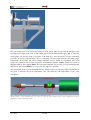
The basic idea to measure the torque precisely, is to mount the torque sensor as close to the probe as
possible. Since the torque sensor cannot stand the heat, we had to mount the senor outside the oven,
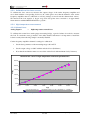
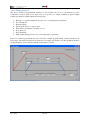
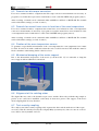
right after the oil feed system. In Ill. 11 the torque sensor is shown in light green.
The arbor used to be driven over a V-belt form the motor, which was mounted in the support. This is
not possible anymore, since the torque sensor uses up to much space. Therefore we had to find a new
way, how to bring the rotation from the motor onto the arbor. One possibility is to keep the motor in
the support (where it was) and bring the radiation over V-belt or a chain and a rather complicated
redirection device to the arbor. With this solution it will be very complicated to predict the behavior
and to determine the characteristic frequencies, because the rotation and the forces are passed through
many parts.
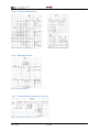
Ill. 10: Schema of the old system
The idea to solve this problem is to simplify the system as much as possible. A more simple solution,
than the one described above is to extend the arbor of the motor, so it will reach the outside of the
support (through a hole). From here the rotation can be brought directly to the torque sensor over a Vbelt or a chain, since we now got enough space to get behind the torque sensor with a belt. The
problem with belts and chains is that their elastic behavior is difficult to determine and to predict. To
V This text is partly similar with the text from the documentation of the first term project
Damian Frey
Simon Wüest
9 / 69
High-Temperature Tribometer